EP2236815A2 - Station de transformation électrique liée à la mer, notamment pour une éolienne - Google Patents
Station de transformation électrique liée à la mer, notamment pour une éolienne Download PDFInfo
- Publication number
- EP2236815A2 EP2236815A2 EP10000243A EP10000243A EP2236815A2 EP 2236815 A2 EP2236815 A2 EP 2236815A2 EP 10000243 A EP10000243 A EP 10000243A EP 10000243 A EP10000243 A EP 10000243A EP 2236815 A2 EP2236815 A2 EP 2236815A2
- Authority
- EP
- European Patent Office
- Prior art keywords
- pontoon
- substation
- electrical
- electrical components
- sea
- Prior art date
- Legal status (The legal status is an assumption and is not a legal conclusion. Google has not performed a legal analysis and makes no representation as to the accuracy of the status listed.)
- Withdrawn
Links
- 238000007667 floating Methods 0.000 claims abstract description 3
- 238000000034 method Methods 0.000 claims description 4
- 238000010248 power generation Methods 0.000 claims description 3
- 238000012544 monitoring process Methods 0.000 claims 1
- 230000005611 electricity Effects 0.000 abstract 1
- 238000005553 drilling Methods 0.000 description 7
- 238000009434 installation Methods 0.000 description 4
- 241000196324 Embryophyta Species 0.000 description 3
- XLYOFNOQVPJJNP-UHFFFAOYSA-N water Substances O XLYOFNOQVPJJNP-UHFFFAOYSA-N 0.000 description 3
- 150000003839 salts Chemical class 0.000 description 2
- 241001247287 Pentalinon luteum Species 0.000 description 1
- 238000004378 air conditioning Methods 0.000 description 1
- 238000004873 anchoring Methods 0.000 description 1
- 230000001143 conditioned effect Effects 0.000 description 1
- 238000010276 construction Methods 0.000 description 1
- 230000007797 corrosion Effects 0.000 description 1
- 238000005260 corrosion Methods 0.000 description 1
- 239000010779 crude oil Substances 0.000 description 1
- 238000000605 extraction Methods 0.000 description 1
- 238000009472 formulation Methods 0.000 description 1
- 238000011990 functional testing Methods 0.000 description 1
- 238000012423 maintenance Methods 0.000 description 1
- 230000007257 malfunction Effects 0.000 description 1
- 238000004519 manufacturing process Methods 0.000 description 1
- 239000000203 mixture Substances 0.000 description 1
- 230000035484 reaction time Effects 0.000 description 1
- 239000013535 sea water Substances 0.000 description 1
Images


Classifications
-
- F—MECHANICAL ENGINEERING; LIGHTING; HEATING; WEAPONS; BLASTING
- F03—MACHINES OR ENGINES FOR LIQUIDS; WIND, SPRING, OR WEIGHT MOTORS; PRODUCING MECHANICAL POWER OR A REACTIVE PROPULSIVE THRUST, NOT OTHERWISE PROVIDED FOR
- F03D—WIND MOTORS
- F03D13/00—Assembly, mounting or commissioning of wind motors; Arrangements specially adapted for transporting wind motor components
- F03D13/20—Arrangements for mounting or supporting wind motors; Masts or towers for wind motors
- F03D13/25—Arrangements for mounting or supporting wind motors; Masts or towers for wind motors specially adapted for offshore installation
-
- F—MECHANICAL ENGINEERING; LIGHTING; HEATING; WEAPONS; BLASTING
- F03—MACHINES OR ENGINES FOR LIQUIDS; WIND, SPRING, OR WEIGHT MOTORS; PRODUCING MECHANICAL POWER OR A REACTIVE PROPULSIVE THRUST, NOT OTHERWISE PROVIDED FOR
- F03D—WIND MOTORS
- F03D13/00—Assembly, mounting or commissioning of wind motors; Arrangements specially adapted for transporting wind motor components
- F03D13/10—Assembly of wind motors; Arrangements for erecting wind motors
-
- F—MECHANICAL ENGINEERING; LIGHTING; HEATING; WEAPONS; BLASTING
- F03—MACHINES OR ENGINES FOR LIQUIDS; WIND, SPRING, OR WEIGHT MOTORS; PRODUCING MECHANICAL POWER OR A REACTIVE PROPULSIVE THRUST, NOT OTHERWISE PROVIDED FOR
- F03D—WIND MOTORS
- F03D9/00—Adaptations of wind motors for special use; Combinations of wind motors with apparatus driven thereby; Wind motors specially adapted for installation in particular locations
- F03D9/20—Wind motors characterised by the driven apparatus
- F03D9/25—Wind motors characterised by the driven apparatus the apparatus being an electrical generator
- F03D9/255—Wind motors characterised by the driven apparatus the apparatus being an electrical generator connected to electrical distribution networks; Arrangements therefor
-
- F—MECHANICAL ENGINEERING; LIGHTING; HEATING; WEAPONS; BLASTING
- F05—INDEXING SCHEMES RELATING TO ENGINES OR PUMPS IN VARIOUS SUBCLASSES OF CLASSES F01-F04
- F05B—INDEXING SCHEME RELATING TO WIND, SPRING, WEIGHT, INERTIA OR LIKE MOTORS, TO MACHINES OR ENGINES FOR LIQUIDS COVERED BY SUBCLASSES F03B, F03D AND F03G
- F05B2240/00—Components
- F05B2240/90—Mounting on supporting structures or systems
- F05B2240/95—Mounting on supporting structures or systems offshore
-
- H—ELECTRICITY
- H01—ELECTRIC ELEMENTS
- H01F—MAGNETS; INDUCTANCES; TRANSFORMERS; SELECTION OF MATERIALS FOR THEIR MAGNETIC PROPERTIES
- H01F27/00—Details of transformers or inductances, in general
- H01F27/06—Mounting, supporting or suspending transformers, reactors or choke coils not being of the signal type
-
- H—ELECTRICITY
- H01—ELECTRIC ELEMENTS
- H01F—MAGNETS; INDUCTANCES; TRANSFORMERS; SELECTION OF MATERIALS FOR THEIR MAGNETIC PROPERTIES
- H01F27/00—Details of transformers or inductances, in general
- H01F27/40—Structural association with built-in electric component, e.g. fuse
-
- Y—GENERAL TAGGING OF NEW TECHNOLOGICAL DEVELOPMENTS; GENERAL TAGGING OF CROSS-SECTIONAL TECHNOLOGIES SPANNING OVER SEVERAL SECTIONS OF THE IPC; TECHNICAL SUBJECTS COVERED BY FORMER USPC CROSS-REFERENCE ART COLLECTIONS [XRACs] AND DIGESTS
- Y02—TECHNOLOGIES OR APPLICATIONS FOR MITIGATION OR ADAPTATION AGAINST CLIMATE CHANGE
- Y02E—REDUCTION OF GREENHOUSE GAS [GHG] EMISSIONS, RELATED TO ENERGY GENERATION, TRANSMISSION OR DISTRIBUTION
- Y02E10/00—Energy generation through renewable energy sources
- Y02E10/70—Wind energy
- Y02E10/72—Wind turbines with rotation axis in wind direction
-
- Y—GENERAL TAGGING OF NEW TECHNOLOGICAL DEVELOPMENTS; GENERAL TAGGING OF CROSS-SECTIONAL TECHNOLOGIES SPANNING OVER SEVERAL SECTIONS OF THE IPC; TECHNICAL SUBJECTS COVERED BY FORMER USPC CROSS-REFERENCE ART COLLECTIONS [XRACs] AND DIGESTS
- Y02—TECHNOLOGIES OR APPLICATIONS FOR MITIGATION OR ADAPTATION AGAINST CLIMATE CHANGE
- Y02E—REDUCTION OF GREENHOUSE GAS [GHG] EMISSIONS, RELATED TO ENERGY GENERATION, TRANSMISSION OR DISTRIBUTION
- Y02E10/00—Energy generation through renewable energy sources
- Y02E10/70—Wind energy
- Y02E10/727—Offshore wind turbines
Definitions
- the invention relates to a seenotes electrical substation in particular for a wind turbine.
- the substation is usually provided in the vicinity of the windmills.
- a working platform is set up in the sea for this purpose, on the surface of which the electrical components of the substation, that is, for example, transformers, switches and the like, are arranged.
- the components are usually housed in containers or the like.
- a foundation structure for example by means of a grid construction or a so-called monopile or tripod on the seabed.
- the foundation structure is manufactured on land and set up at the desired location with the help of ship cranes in the sea. Thereafter, the work platform can be mounted on the foundation structure.
- a disadvantage of such a substation results from the fact that a great deal of effort has to be made to protect the electrical components against the harsh sea climate, in particular against the aggressive salt water. Furthermore, the establishment of the foundation structure and the assembly of the work platform is associated with a great effort.
- the object of the invention is to provide a see-bound electrical substation, which is improved in view of the above disadvantages.
- the see-bound substation is provided with electrical components, in particular with a transformer, a circuit breaker and the like, which electrical energy can be supplied, and with which a high voltage can be generated.
- electrical components of the substation according to the invention are housed in the interior of a buoyant pontoon.
- the advantage is achieved that the components are largely spared from the aggressive ocean climate.
- the cost of corrosion protection of the components can thus be reduced.
- air conditioning of the interior of the pontoon a further improvement of the operating conditions for the electrical components of the substation. This makes it possible to further simplify the components and their interconnection.
- the electrical components of the substation are easily accessible in any weather. This facilitates the operation and maintenance of the components.
- the floating design of the pontoon has the advantage that the substation can already be installed on land in the interior of the pontoon. This makes the installation of the substation much easier and makes this installation weather-independent. As a result, the assembly time is reduced. The ready-built in the pontoon substation is then towed in a simple manner to the intended location and anchored there. The effort for this part of the installation is much easier and thus cheaper than before.
- the further advantage is achieved that the surface of the pontoon can be fed to other uses.
- spare parts of the substation and possibly also of the associated power generation plants can be stored there, which previously had to be always delivered by land in case of need.
- the reaction time can be significantly reduced to a malfunction and thus a further cost savings can be achieved.
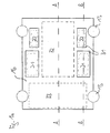
- FIGS. 1a . 1b . 1c show schematic plan views of an embodiment of a sundial electrical substation according to the invention and the FIGS. 2a, 2b show schematic cross sections of the substation of FIGS. 1a . 1b . 1c along the lines A, B of FIG. 1a ,
- a substation 10 is shown, which is preferably used in connection with a wind turbine, which is placed in the sea or in a lake.
- a wind turbine which is placed in the sea or in a lake.
- the several wind turbines deliver the energy generated in each case via submarine cable to the substation 10.
- the supplied electrical energy is converted by the substation 10 in a desired high voltage and fed via further submarine cable in a shore or sea-bound energy supply network.
- substation 10 shown in the figures is connected to at least one submarine cable, via which electrical energy is supplied to the substation 10, as well as with at least one further submarine cable, via which said high voltage is transmitted to the power supply network.
- the said submarine cables are not shown in the figures.
- the substation 10 is housed in the interior of a buoyant pontoon 12.
- Such a pontoon is known as such and is used in crude oil extraction.
- a drilling rig with a derrick and a work crane placed on the surface of the drilling platform.
- the drilling platform is part of a buoyant pontoon, which is built by means of a plurality of pillars on the seabed.
- the pontoon is towed to its location with raised columns. At the site, the columns are lowered to the seabed and the drilling platform is set up.
- the pontoon 12 is approximately cuboid and has for example a length of about 35 to 45 meters, a width of about 25 to 35 meters and a height of about 6 to 8 meters.
- the pontoon 12 has four columns 13, with which the pontoon 12 can be placed on the seabed.
- the pontoon 12 has a bottom 14, a false ceiling 15 and a platform 16, which are surrounded by outer walls 17.
- the pontoon 12 forms a buoyant tub.
- the interior of the pontoon 12 is substantially inaccessible to seawater.
- the pontoon 12 may also have a different cross-sectional shape.
- the pontoon 12 may also be triangular or substantially round.
- the pontoon 12 can also have several false ceilings or no false ceiling, so that therefore only one or more than two levels are present.
- the bottom 14, the intermediate wall 15 and the platform 16 are arranged approximately parallel to each other, while the outer walls 17 are aligned approximately perpendicular thereto.
- the bottom 14, the false ceiling 15 and the platform 16 are attached to each other by means not shown, approximately vertically oriented supports or the like, so that a total of a dimensionally stable structure is formed.
- the design and Dimensioning of the floor 14, the false ceiling 15, the platform 16, the outer walls 17 and the other supports and the like is selected such that even heavy electrical components of the substation 10 in the interior of the pontoon 12 can be accommodated.
- the false ceiling 15 divides the interior of the pontoon into an upper level 18 and an approximately vertical lower level lower level 19. Each of the levels has a height of about 3 to 4 meters. As already mentioned, the false ceiling 15 is supported by means of supports and the like, and thus sustainable. As already mentioned, these supports are not shown in the figures. Only because of these missing supports the false ceiling 15 in the schematic cross sections of FIGS. 2a, 2b to float.
- the lower level 19 builds up on the floor 14 and is in the plan view of Figure 1c as well as in the cross sections of FIGS. 2a, 2b shown.
- Two transformers 21, in particular two hermetic transformers, as well as two chokes 22, in particular two compensation chokes, are placed on the floor 14 by way of example.
- the aforementioned electrical components are - as in the Figure 1c shown - arranged at the outer edge of the bottom 14 is substantially symmetrical to each other.
- the area 24 between the transformers 21 and the chokes 22 is used in the lower level 19 to accommodate electrical cables.
- the remaining area 25 in the lower level 19 is not occupied by electrical components of the substation 10 and can be used elsewhere.
- the transformers 21, the chokes 22 and the power switches 23 extend in height over both levels 18, 19.
- the transformers 21, the chokes 22 and the power switches 23 are therefore also present in the upper level 18 of the pontoon 12.
- the upper level 18 builds on the false ceiling 15 and is in the plan view of FIG. 1b as well as in the cross sections of FIGS. 2a, 2b shown.
- the false ceiling 15 has openings through which - as mentioned - the transformers 21, the chokes 22 and the power switches 23 extend from the lower level 19 into the upper level 18. Furthermore, further power switches 27 and further reactors 28 are placed on the false ceiling 15, in the area between the openings for the transformers 21, the chokes 22 and the power switches 23.
- a switch room is housed, which includes a plurality of cabinets 29, over which the transformers 21, the chokes 22, 28 and the circuit breakers 23, 27 can be monitored and operated by operating personnel.
- the remaining area in the upper level 18 is not occupied by electrical components of the substation 10 and can be used elsewhere.
- the transformers 21 and the throttles 22 extend beyond the two planes 18, 19 with respect to their height.
- the transformers 21 and the chokes 22 are therefore over the platform 16 via.
- openings are included for this purpose.
- the transformers 21 and the throttles 22 are closed above the platform 16 by means of lids 31. It is understood that the openings in the platform 16 can be dispensed with, if the height of the transformers 21 and chokes 22 permits so long as the transformers 21 and chokes 22 can thus be accommodated completely in the lower and upper levels 18, 19.
- the platform 16 is in the plan view of FIG. 1a as well as in the cross sections 2a, 2b shown.
- the platform 16 forms the ceiling of the upper level 18 and represents the surface of the pontoon 12.
- the area between the transformers 21 and chokes 22 is provided on the surface of the platform 16 as a storage area.
- 32 containers can be parked there, in which operating and / or spare parts for the substation 10 and possibly also for the associated n wind turbine / n are stored.
- the platform 16 is used as a heliport, so that this no additional platform is required.
- an area can be provided on the surface of the platform, can be placed on the living container 33 or the like for the operating personnel of the substation 10.
- the reactors 28 are used to compensate the submarine cable coming from the wind turbine (s). With the help of the circuit breaker 27, the supply of electrical energy can be interrupted via this submarine cable, if necessary.
- the electric power supplied to the substation 10 via the submarine cable is converted by the transformer 21 into the desired high voltage.
- the transformer 21, the power switch 23 are arranged downstream, in order to switch off the generated high voltage, if necessary, can.
- With the help of the chokes 22 is a compensation of the country or see-bound energy supply network leading submarine cable made.
- the electrical cables are preferably guided in the region 24 of the lower level 19.
- the submarine cables can be supplied, for example, via the columns 13 to the electrical components of the substation 10.
- the electrical components of the substation 10 are largely protected against salt water and the like. Furthermore, the interior of the pontoon 12 can be conditioned.
- the installation of the substation 10 takes place on land. There, the described electrical components of the substation 10 can be installed in the interior of the pontoon 12. Likewise, functional tests and the like can already be carried out on land.
- the finished pontoon 12 with the substation 10 contained therein is then towed by a ship to the intended location. There, the pontoon 12 is established by anchoring the columns 13 firmly on the seabed and anchored. A crane is not required. At sea, it is then only necessary to connect the submarine cable and take the substation 10 in operation.
- the dimensioning of the pontoon 12 must be made such that the pontoon 12 is still buoyant even with the housed in its interior electrical components of the substation 10. However, this is usually no problem with the exemplified length, width and height dimensions of the pontoon 12.
- the described substation 10 can also be used when the wind turbine, ie in particular the energy-generating wind turbine, is constructed directly on the platform 16 of the pontoon 12. It is also understood that the substation 10 can also be used in other power generation plants, for example in wave power plants or similar water-based plants.
Applications Claiming Priority (1)
| Application Number | Priority Date | Filing Date | Title |
|---|---|---|---|
| DE102009014427A DE102009014427A1 (de) | 2009-03-26 | 2009-03-26 | Seegebundenes elektrisches Umspannwerk insbesondere für eine Windkraftanlage |
Publications (2)
| Publication Number | Publication Date |
|---|---|
| EP2236815A2 true EP2236815A2 (fr) | 2010-10-06 |
| EP2236815A3 EP2236815A3 (fr) | 2013-03-27 |
Family
ID=42321109
Family Applications (1)
| Application Number | Title | Priority Date | Filing Date |
|---|---|---|---|
| EP10000243A Withdrawn EP2236815A3 (fr) | 2009-03-26 | 2010-01-13 | Station de transformation électrique liée à la mer, notamment pour une éolienne |
Country Status (2)
| Country | Link |
|---|---|
| EP (1) | EP2236815A3 (fr) |
| DE (1) | DE102009014427A1 (fr) |
Citations (1)
| Publication number | Priority date | Publication date | Assignee | Title |
|---|---|---|---|---|
| EP0959182B1 (fr) | 1998-05-20 | 2003-04-02 | Doris Engineering | Plate-forme marine auto-élévatrice et son procédé d'installation |
Family Cites Families (6)
| Publication number | Priority date | Publication date | Assignee | Title |
|---|---|---|---|---|
| DE4324397A1 (de) * | 1993-07-21 | 1995-02-02 | Ingenieurzentrum Schiffbau Gmb | Schwimmende Plattform |
| DE19514034C5 (de) * | 1995-04-13 | 2011-03-10 | Wolfgang Roehr | Brauereianlage |
| KR100766185B1 (ko) * | 2005-05-18 | 2007-10-10 | 박재욱 | 해상 복합화력 발전소 |
| DE102005043671A1 (de) * | 2005-09-14 | 2007-03-15 | Neißekies Baustoffwerke GmbH | Ponton als Fundament für Aufbauten und für schwimmende Anlagen |
| FR2892432B1 (fr) * | 2005-10-25 | 2009-07-17 | Doris Engineering | Ouvrage urbain maritime |
| DE102006025832A1 (de) * | 2006-06-02 | 2007-12-06 | Joachim Falkenhagen | Bei Seegang überspültes rohrförmiges Bauwerk und darin unter der Wasserlinie untergebrachter Transformator |
-
2009
- 2009-03-26 DE DE102009014427A patent/DE102009014427A1/de not_active Withdrawn
-
2010
- 2010-01-13 EP EP10000243A patent/EP2236815A3/fr not_active Withdrawn
Patent Citations (1)
| Publication number | Priority date | Publication date | Assignee | Title |
|---|---|---|---|---|
| EP0959182B1 (fr) | 1998-05-20 | 2003-04-02 | Doris Engineering | Plate-forme marine auto-élévatrice et son procédé d'installation |
Also Published As
| Publication number | Publication date |
|---|---|
| EP2236815A3 (fr) | 2013-03-27 |
| DE102009014427A1 (de) | 2010-09-30 |
Similar Documents
| Publication | Publication Date | Title |
|---|---|---|
| EP2941823B1 (fr) | Poste de conversion équipé d'un redresseur à diodes | |
| EP1071883B2 (fr) | Centrale eolienne dote d'un transformateur | |
| EP2811160B1 (fr) | Installation de production d'énergie éolienne en mer | |
| EP1831901B1 (fr) | Composant electrique a circuit de refroidissement pour une utilisation sous-marine | |
| DE10013442C1 (de) | Windkraftanlage | |
| EP1546550B1 (fr) | Éolienne mobile | |
| WO2012072063A2 (fr) | Segment de pied de tour d'éolienne en mer, éolienne en mer comportant un tel segment de pied de tour et procédé d'installation d'une telle éolienne en mer | |
| DE102012003572A1 (de) | Offshore-Plattform-Konstruktion sowie Verfahren zur Errichtung einer Offshore-Windturbinenstation | |
| DE202014004373U1 (de) | ln die Gründungsstruktur eines Offshore-Bauwerkes integriertes Umspannwerk für Windparks | |
| DE102016219413A1 (de) | Elektrische Baueinheit für eine Windenergieanlage | |
| DE4106976A1 (de) | Windkraftanlagen | |
| EP3683438B1 (fr) | Centrale d'accumulation par pompage dans un plan d'eau et procédé de fonctionnement | |
| DE202014004372U1 (de) | Offshore Windpark mit mindestens einem seeseitigen Umspannwerk | |
| EP2811159B1 (fr) | Installation de production d'énergie éolienne en mer | |
| EP3530809B1 (fr) | Structure de raccordement pour une installation marine | |
| EP4013961B1 (fr) | Éolienne flottante comprenant une sous-station électrique intégrée | |
| DE102018210623A1 (de) | Schwimmkörper, Windkraftanlage und Hochseewindpark | |
| EP2725223B1 (fr) | Groupe d'installations éoliennes | |
| EP2237384A2 (fr) | Système de refroidissement pour une station de transformation électrique, notamment pour une éolienne | |
| EP3527819A1 (fr) | Construction de toiture pour une sous-station offshore | |
| EP2236815A2 (fr) | Station de transformation électrique liée à la mer, notamment pour une éolienne | |
| DE102013019229B4 (de) | Gezeitengenerator | |
| EP1321669B1 (fr) | Système de transport et d'installation d'éoliennes marines | |
| DE102019003203B4 (de) | Pumpspeicherwerk | |
| DE102020100150A1 (de) | Offshore-Windkraftanlage |
Legal Events
| Date | Code | Title | Description |
|---|---|---|---|
| PUAI | Public reference made under article 153(3) epc to a published international application that has entered the european phase |
Free format text: ORIGINAL CODE: 0009012 |
|
| AK | Designated contracting states |
Kind code of ref document: A2 Designated state(s): AT BE BG CH CY CZ DE DK EE ES FI FR GB GR HR HU IE IS IT LI LT LU LV MC MK MT NL NO PL PT RO SE SI SK SM TR |
|
| AX | Request for extension of the european patent |
Extension state: AL BA RS |
|
| PUAL | Search report despatched |
Free format text: ORIGINAL CODE: 0009013 |
|
| AK | Designated contracting states |
Kind code of ref document: A3 Designated state(s): AT BE BG CH CY CZ DE DK EE ES FI FR GB GR HR HU IE IS IT LI LT LU LV MC MK MT NL NO PL PT RO SE SI SK SM TR |
|
| AX | Request for extension of the european patent |
Extension state: AL BA RS |
|
| RIC1 | Information provided on ipc code assigned before grant |
Ipc: F03D 1/00 20060101AFI20130219BHEP Ipc: F03D 11/04 20060101ALI20130219BHEP |
|
| 17P | Request for examination filed |
Effective date: 20130925 |
|
| RBV | Designated contracting states (corrected) |
Designated state(s): AT BE BG CH CY CZ DE DK EE ES FI FR GB GR HR HU IE IS IT LI LT LU LV MC MK MT NL NO PL PT RO SE SI SK SM TR |
|
| RAP1 | Party data changed (applicant data changed or rights of an application transferred) |
Owner name: ALSTOM GRID GMBH |
|
| RAP1 | Party data changed (applicant data changed or rights of an application transferred) |
Owner name: ALSTOM TECHNOLOGY LTD |
|
| RIC1 | Information provided on ipc code assigned before grant |
Ipc: F03D 13/25 20160101AFI20170720BHEP |
|
| GRAP | Despatch of communication of intention to grant a patent |
Free format text: ORIGINAL CODE: EPIDOSNIGR1 |
|
| INTG | Intention to grant announced |
Effective date: 20170912 |
|
| STAA | Information on the status of an ep patent application or granted ep patent |
Free format text: STATUS: THE APPLICATION IS DEEMED TO BE WITHDRAWN |
|
| 18D | Application deemed to be withdrawn |
Effective date: 20180123 |