EP2236815A2 - Sea-based electrical transformer, in particular for a wind power system - Google Patents
Sea-based electrical transformer, in particular for a wind power system Download PDFInfo
- Publication number
- EP2236815A2 EP2236815A2 EP10000243A EP10000243A EP2236815A2 EP 2236815 A2 EP2236815 A2 EP 2236815A2 EP 10000243 A EP10000243 A EP 10000243A EP 10000243 A EP10000243 A EP 10000243A EP 2236815 A2 EP2236815 A2 EP 2236815A2
- Authority
- EP
- European Patent Office
- Prior art keywords
- pontoon
- substation
- electrical
- electrical components
- sea
- Prior art date
- Legal status (The legal status is an assumption and is not a legal conclusion. Google has not performed a legal analysis and makes no representation as to the accuracy of the status listed.)
- Withdrawn
Links
- 238000007667 floating Methods 0.000 claims abstract description 3
- 238000000034 method Methods 0.000 claims description 4
- 238000010248 power generation Methods 0.000 claims description 3
- 238000012544 monitoring process Methods 0.000 claims 1
- 230000005611 electricity Effects 0.000 abstract 1
- 238000005553 drilling Methods 0.000 description 7
- 238000009434 installation Methods 0.000 description 4
- 241000196324 Embryophyta Species 0.000 description 3
- XLYOFNOQVPJJNP-UHFFFAOYSA-N water Substances O XLYOFNOQVPJJNP-UHFFFAOYSA-N 0.000 description 3
- 150000003839 salts Chemical class 0.000 description 2
- 241001247287 Pentalinon luteum Species 0.000 description 1
- 238000004378 air conditioning Methods 0.000 description 1
- 238000004873 anchoring Methods 0.000 description 1
- 230000001143 conditioned effect Effects 0.000 description 1
- 238000010276 construction Methods 0.000 description 1
- 230000007797 corrosion Effects 0.000 description 1
- 238000005260 corrosion Methods 0.000 description 1
- 239000010779 crude oil Substances 0.000 description 1
- 238000000605 extraction Methods 0.000 description 1
- 238000009472 formulation Methods 0.000 description 1
- 238000011990 functional testing Methods 0.000 description 1
- 238000012423 maintenance Methods 0.000 description 1
- 230000007257 malfunction Effects 0.000 description 1
- 238000004519 manufacturing process Methods 0.000 description 1
- 239000000203 mixture Substances 0.000 description 1
- 230000035484 reaction time Effects 0.000 description 1
- 239000013535 sea water Substances 0.000 description 1
Images


Classifications
-
- F—MECHANICAL ENGINEERING; LIGHTING; HEATING; WEAPONS; BLASTING
- F03—MACHINES OR ENGINES FOR LIQUIDS; WIND, SPRING, OR WEIGHT MOTORS; PRODUCING MECHANICAL POWER OR A REACTIVE PROPULSIVE THRUST, NOT OTHERWISE PROVIDED FOR
- F03D—WIND MOTORS
- F03D13/00—Assembly, mounting or commissioning of wind motors; Arrangements specially adapted for transporting wind motor components
- F03D13/20—Arrangements for mounting or supporting wind motors; Masts or towers for wind motors
- F03D13/25—Arrangements for mounting or supporting wind motors; Masts or towers for wind motors specially adapted for offshore installation
-
- F—MECHANICAL ENGINEERING; LIGHTING; HEATING; WEAPONS; BLASTING
- F03—MACHINES OR ENGINES FOR LIQUIDS; WIND, SPRING, OR WEIGHT MOTORS; PRODUCING MECHANICAL POWER OR A REACTIVE PROPULSIVE THRUST, NOT OTHERWISE PROVIDED FOR
- F03D—WIND MOTORS
- F03D13/00—Assembly, mounting or commissioning of wind motors; Arrangements specially adapted for transporting wind motor components
- F03D13/10—Assembly of wind motors; Arrangements for erecting wind motors
-
- F—MECHANICAL ENGINEERING; LIGHTING; HEATING; WEAPONS; BLASTING
- F03—MACHINES OR ENGINES FOR LIQUIDS; WIND, SPRING, OR WEIGHT MOTORS; PRODUCING MECHANICAL POWER OR A REACTIVE PROPULSIVE THRUST, NOT OTHERWISE PROVIDED FOR
- F03D—WIND MOTORS
- F03D9/00—Adaptations of wind motors for special use; Combinations of wind motors with apparatus driven thereby; Wind motors specially adapted for installation in particular locations
- F03D9/20—Wind motors characterised by the driven apparatus
- F03D9/25—Wind motors characterised by the driven apparatus the apparatus being an electrical generator
- F03D9/255—Wind motors characterised by the driven apparatus the apparatus being an electrical generator connected to electrical distribution networks; Arrangements therefor
-
- F—MECHANICAL ENGINEERING; LIGHTING; HEATING; WEAPONS; BLASTING
- F05—INDEXING SCHEMES RELATING TO ENGINES OR PUMPS IN VARIOUS SUBCLASSES OF CLASSES F01-F04
- F05B—INDEXING SCHEME RELATING TO WIND, SPRING, WEIGHT, INERTIA OR LIKE MOTORS, TO MACHINES OR ENGINES FOR LIQUIDS COVERED BY SUBCLASSES F03B, F03D AND F03G
- F05B2240/00—Components
- F05B2240/90—Mounting on supporting structures or systems
- F05B2240/95—Mounting on supporting structures or systems offshore
-
- H—ELECTRICITY
- H01—ELECTRIC ELEMENTS
- H01F—MAGNETS; INDUCTANCES; TRANSFORMERS; SELECTION OF MATERIALS FOR THEIR MAGNETIC PROPERTIES
- H01F27/00—Details of transformers or inductances, in general
- H01F27/06—Mounting, supporting or suspending transformers, reactors or choke coils not being of the signal type
-
- H—ELECTRICITY
- H01—ELECTRIC ELEMENTS
- H01F—MAGNETS; INDUCTANCES; TRANSFORMERS; SELECTION OF MATERIALS FOR THEIR MAGNETIC PROPERTIES
- H01F27/00—Details of transformers or inductances, in general
- H01F27/40—Structural association with built-in electric component, e.g. fuse
-
- Y—GENERAL TAGGING OF NEW TECHNOLOGICAL DEVELOPMENTS; GENERAL TAGGING OF CROSS-SECTIONAL TECHNOLOGIES SPANNING OVER SEVERAL SECTIONS OF THE IPC; TECHNICAL SUBJECTS COVERED BY FORMER USPC CROSS-REFERENCE ART COLLECTIONS [XRACs] AND DIGESTS
- Y02—TECHNOLOGIES OR APPLICATIONS FOR MITIGATION OR ADAPTATION AGAINST CLIMATE CHANGE
- Y02E—REDUCTION OF GREENHOUSE GAS [GHG] EMISSIONS, RELATED TO ENERGY GENERATION, TRANSMISSION OR DISTRIBUTION
- Y02E10/00—Energy generation through renewable energy sources
- Y02E10/70—Wind energy
- Y02E10/72—Wind turbines with rotation axis in wind direction
-
- Y—GENERAL TAGGING OF NEW TECHNOLOGICAL DEVELOPMENTS; GENERAL TAGGING OF CROSS-SECTIONAL TECHNOLOGIES SPANNING OVER SEVERAL SECTIONS OF THE IPC; TECHNICAL SUBJECTS COVERED BY FORMER USPC CROSS-REFERENCE ART COLLECTIONS [XRACs] AND DIGESTS
- Y02—TECHNOLOGIES OR APPLICATIONS FOR MITIGATION OR ADAPTATION AGAINST CLIMATE CHANGE
- Y02E—REDUCTION OF GREENHOUSE GAS [GHG] EMISSIONS, RELATED TO ENERGY GENERATION, TRANSMISSION OR DISTRIBUTION
- Y02E10/00—Energy generation through renewable energy sources
- Y02E10/70—Wind energy
- Y02E10/727—Offshore wind turbines
Definitions
- the invention relates to a seenotes electrical substation in particular for a wind turbine.
- the substation is usually provided in the vicinity of the windmills.
- a working platform is set up in the sea for this purpose, on the surface of which the electrical components of the substation, that is, for example, transformers, switches and the like, are arranged.
- the components are usually housed in containers or the like.
- a foundation structure for example by means of a grid construction or a so-called monopile or tripod on the seabed.
- the foundation structure is manufactured on land and set up at the desired location with the help of ship cranes in the sea. Thereafter, the work platform can be mounted on the foundation structure.
- a disadvantage of such a substation results from the fact that a great deal of effort has to be made to protect the electrical components against the harsh sea climate, in particular against the aggressive salt water. Furthermore, the establishment of the foundation structure and the assembly of the work platform is associated with a great effort.
- the object of the invention is to provide a see-bound electrical substation, which is improved in view of the above disadvantages.
- the see-bound substation is provided with electrical components, in particular with a transformer, a circuit breaker and the like, which electrical energy can be supplied, and with which a high voltage can be generated.
- electrical components of the substation according to the invention are housed in the interior of a buoyant pontoon.
- the advantage is achieved that the components are largely spared from the aggressive ocean climate.
- the cost of corrosion protection of the components can thus be reduced.
- air conditioning of the interior of the pontoon a further improvement of the operating conditions for the electrical components of the substation. This makes it possible to further simplify the components and their interconnection.
- the electrical components of the substation are easily accessible in any weather. This facilitates the operation and maintenance of the components.
- the floating design of the pontoon has the advantage that the substation can already be installed on land in the interior of the pontoon. This makes the installation of the substation much easier and makes this installation weather-independent. As a result, the assembly time is reduced. The ready-built in the pontoon substation is then towed in a simple manner to the intended location and anchored there. The effort for this part of the installation is much easier and thus cheaper than before.
- the further advantage is achieved that the surface of the pontoon can be fed to other uses.
- spare parts of the substation and possibly also of the associated power generation plants can be stored there, which previously had to be always delivered by land in case of need.
- the reaction time can be significantly reduced to a malfunction and thus a further cost savings can be achieved.
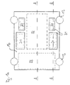
- FIGS. 1a . 1b . 1c show schematic plan views of an embodiment of a sundial electrical substation according to the invention and the FIGS. 2a, 2b show schematic cross sections of the substation of FIGS. 1a . 1b . 1c along the lines A, B of FIG. 1a ,
- a substation 10 is shown, which is preferably used in connection with a wind turbine, which is placed in the sea or in a lake.
- a wind turbine which is placed in the sea or in a lake.
- the several wind turbines deliver the energy generated in each case via submarine cable to the substation 10.
- the supplied electrical energy is converted by the substation 10 in a desired high voltage and fed via further submarine cable in a shore or sea-bound energy supply network.
- substation 10 shown in the figures is connected to at least one submarine cable, via which electrical energy is supplied to the substation 10, as well as with at least one further submarine cable, via which said high voltage is transmitted to the power supply network.
- the said submarine cables are not shown in the figures.
- the substation 10 is housed in the interior of a buoyant pontoon 12.
- Such a pontoon is known as such and is used in crude oil extraction.
- a drilling rig with a derrick and a work crane placed on the surface of the drilling platform.
- the drilling platform is part of a buoyant pontoon, which is built by means of a plurality of pillars on the seabed.
- the pontoon is towed to its location with raised columns. At the site, the columns are lowered to the seabed and the drilling platform is set up.
- the pontoon 12 is approximately cuboid and has for example a length of about 35 to 45 meters, a width of about 25 to 35 meters and a height of about 6 to 8 meters.
- the pontoon 12 has four columns 13, with which the pontoon 12 can be placed on the seabed.
- the pontoon 12 has a bottom 14, a false ceiling 15 and a platform 16, which are surrounded by outer walls 17.
- the pontoon 12 forms a buoyant tub.
- the interior of the pontoon 12 is substantially inaccessible to seawater.
- the pontoon 12 may also have a different cross-sectional shape.
- the pontoon 12 may also be triangular or substantially round.
- the pontoon 12 can also have several false ceilings or no false ceiling, so that therefore only one or more than two levels are present.
- the bottom 14, the intermediate wall 15 and the platform 16 are arranged approximately parallel to each other, while the outer walls 17 are aligned approximately perpendicular thereto.
- the bottom 14, the false ceiling 15 and the platform 16 are attached to each other by means not shown, approximately vertically oriented supports or the like, so that a total of a dimensionally stable structure is formed.
- the design and Dimensioning of the floor 14, the false ceiling 15, the platform 16, the outer walls 17 and the other supports and the like is selected such that even heavy electrical components of the substation 10 in the interior of the pontoon 12 can be accommodated.
- the false ceiling 15 divides the interior of the pontoon into an upper level 18 and an approximately vertical lower level lower level 19. Each of the levels has a height of about 3 to 4 meters. As already mentioned, the false ceiling 15 is supported by means of supports and the like, and thus sustainable. As already mentioned, these supports are not shown in the figures. Only because of these missing supports the false ceiling 15 in the schematic cross sections of FIGS. 2a, 2b to float.
- the lower level 19 builds up on the floor 14 and is in the plan view of Figure 1c as well as in the cross sections of FIGS. 2a, 2b shown.
- Two transformers 21, in particular two hermetic transformers, as well as two chokes 22, in particular two compensation chokes, are placed on the floor 14 by way of example.
- the aforementioned electrical components are - as in the Figure 1c shown - arranged at the outer edge of the bottom 14 is substantially symmetrical to each other.
- the area 24 between the transformers 21 and the chokes 22 is used in the lower level 19 to accommodate electrical cables.
- the remaining area 25 in the lower level 19 is not occupied by electrical components of the substation 10 and can be used elsewhere.
- the transformers 21, the chokes 22 and the power switches 23 extend in height over both levels 18, 19.
- the transformers 21, the chokes 22 and the power switches 23 are therefore also present in the upper level 18 of the pontoon 12.
- the upper level 18 builds on the false ceiling 15 and is in the plan view of FIG. 1b as well as in the cross sections of FIGS. 2a, 2b shown.
- the false ceiling 15 has openings through which - as mentioned - the transformers 21, the chokes 22 and the power switches 23 extend from the lower level 19 into the upper level 18. Furthermore, further power switches 27 and further reactors 28 are placed on the false ceiling 15, in the area between the openings for the transformers 21, the chokes 22 and the power switches 23.
- a switch room is housed, which includes a plurality of cabinets 29, over which the transformers 21, the chokes 22, 28 and the circuit breakers 23, 27 can be monitored and operated by operating personnel.
- the remaining area in the upper level 18 is not occupied by electrical components of the substation 10 and can be used elsewhere.
- the transformers 21 and the throttles 22 extend beyond the two planes 18, 19 with respect to their height.
- the transformers 21 and the chokes 22 are therefore over the platform 16 via.
- openings are included for this purpose.
- the transformers 21 and the throttles 22 are closed above the platform 16 by means of lids 31. It is understood that the openings in the platform 16 can be dispensed with, if the height of the transformers 21 and chokes 22 permits so long as the transformers 21 and chokes 22 can thus be accommodated completely in the lower and upper levels 18, 19.
- the platform 16 is in the plan view of FIG. 1a as well as in the cross sections 2a, 2b shown.
- the platform 16 forms the ceiling of the upper level 18 and represents the surface of the pontoon 12.
- the area between the transformers 21 and chokes 22 is provided on the surface of the platform 16 as a storage area.
- 32 containers can be parked there, in which operating and / or spare parts for the substation 10 and possibly also for the associated n wind turbine / n are stored.
- the platform 16 is used as a heliport, so that this no additional platform is required.
- an area can be provided on the surface of the platform, can be placed on the living container 33 or the like for the operating personnel of the substation 10.
- the reactors 28 are used to compensate the submarine cable coming from the wind turbine (s). With the help of the circuit breaker 27, the supply of electrical energy can be interrupted via this submarine cable, if necessary.
- the electric power supplied to the substation 10 via the submarine cable is converted by the transformer 21 into the desired high voltage.
- the transformer 21, the power switch 23 are arranged downstream, in order to switch off the generated high voltage, if necessary, can.
- With the help of the chokes 22 is a compensation of the country or see-bound energy supply network leading submarine cable made.
- the electrical cables are preferably guided in the region 24 of the lower level 19.
- the submarine cables can be supplied, for example, via the columns 13 to the electrical components of the substation 10.
- the electrical components of the substation 10 are largely protected against salt water and the like. Furthermore, the interior of the pontoon 12 can be conditioned.
- the installation of the substation 10 takes place on land. There, the described electrical components of the substation 10 can be installed in the interior of the pontoon 12. Likewise, functional tests and the like can already be carried out on land.
- the finished pontoon 12 with the substation 10 contained therein is then towed by a ship to the intended location. There, the pontoon 12 is established by anchoring the columns 13 firmly on the seabed and anchored. A crane is not required. At sea, it is then only necessary to connect the submarine cable and take the substation 10 in operation.
- the dimensioning of the pontoon 12 must be made such that the pontoon 12 is still buoyant even with the housed in its interior electrical components of the substation 10. However, this is usually no problem with the exemplified length, width and height dimensions of the pontoon 12.
- the described substation 10 can also be used when the wind turbine, ie in particular the energy-generating wind turbine, is constructed directly on the platform 16 of the pontoon 12. It is also understood that the substation 10 can also be used in other power generation plants, for example in wave power plants or similar water-based plants.
Abstract
Description
Die Erfindung betrifft ein seegebundenes elektrisches Umspannwerk insbesondere für eine Windkraftanlage.The invention relates to a seegebundenes electrical substation in particular for a wind turbine.
Bei der Gewinnung von elektrischer Energie kommen immer häufiger Windkraftanlagen zum Einsatz. Es sind sogenannte Off-Shore Windparks bekannt, bei denen in einem örtlichen Bereich des Meeres mehrere Windräder betrieben werden. Deren erzeugte Energie wird über ein Seekabel an ein gemeinsames Umspannwerk weitergegeben. Dort wird die elektrische Energie in eine erwünschte Hochspannung umgeformt und dann über ein weiteres Seekabel an einen land- oder seegebundenen Netzeinspeisungspunkt eines Energieversorgungsnetzes weitergegeben.In the production of electrical energy more and more wind turbines are used. There are so-called off-shore wind farms are known in which several wind turbines are operated in a local area of the sea. Their generated energy is transmitted via a submarine cable to a common substation. There, the electrical energy is converted into a desired high voltage and then passed through another submarine cable to a shore or sea-bound power supply point of a power grid.
Das Umspannwerk ist üblicherweise in der näheren Umgebung der Windräder vorgesehen. Bei Off-Shore Windparks wird hierzu eine Arbeitsplattform im Meer aufgestellt, auf deren Oberfläche die elektrischen Komponenten des Umspannwerks, also beispielsweise Transformatoren, Schalter und dergleichen, angeordnet sind. Zum Schutz gegen das Meeresklima sind die Komponenten zumeist in Containern oder dergleichen untergebracht.The substation is usually provided in the vicinity of the windmills. For offshore wind farms, a working platform is set up in the sea for this purpose, on the surface of which the electrical components of the substation, that is, for example, transformers, switches and the like, are arranged. For protection against the marine climate, the components are usually housed in containers or the like.
Zur Verwendung bei einem Umspannwerk ist es beispielsweise bekannt, die Arbeitsplattform mittels einer Gründungsstruktur, beispielsweise mittels einer Gitterkonstruktion oder eines sogenannten Monopile oder Tripod auf dem Meeresboden zu errichten. Die Gründungsstruktur wird an Land gefertigt und am erwünschten Standort mit Hilfe von Schiffskranen im Meer aufgestellt. Danach kann die Arbeitsplattform auf der Gründungsstruktur montiert werden.For use in a substation, it is known, for example, to build the working platform by means of a foundation structure, for example by means of a grid construction or a so-called monopile or tripod on the seabed. The foundation structure is manufactured on land and set up at the desired location with the help of ship cranes in the sea. Thereafter, the work platform can be mounted on the foundation structure.
Ein Nachteil eines derartigen Umspannwerks ergibt sich daraus, dass ein hoher Aufwand betrieben werden muss, um die elektrischen Komponenten gegen das harte Meeresklima, insbesondere gegen das aggressive Salzwasser zu schützen. Weiterhin ist die Errichtung der Gründungsstruktur und die Montage der Arbeitsplattform mit einem großen Aufwand verbunden.A disadvantage of such a substation results from the fact that a great deal of effort has to be made to protect the electrical components against the harsh sea climate, in particular against the aggressive salt water. Furthermore, the establishment of the foundation structure and the assembly of the work platform is associated with a great effort.
Aufgabe der Erfindung ist es, ein seegebundenes elektrisches Umspannwerk zu schaffen, das im Hinblick auf die vorstehenden Nachteile verbessert ist.The object of the invention is to provide a see-bound electrical substation, which is improved in view of the above disadvantages.
Diese Aufgabe wird durch ein Umspannwerk nach dem Anspruch 1, durch einen schwimmfähigen Ponton nach dem Anspruch 2 sowie durch ein Verfahren zur Installation des Umspannwerks oder des Pontons nach dem Anspruch 11 gelöst.This object is achieved by a substation according to claim 1, by a buoyant pontoon according to claim 2 and by a method for installing the substation or pontoon according to claim 11.
Das seegebundene Umspannwerk ist mit elektrischen Komponenten versehen, insbesondere mit einem Transformator, einem Leistungsschalter und dergleichen, denen elektrische Energie zuführbar ist, und mit denen eine Hochspannung erzeugbar ist. Diese elektrischen Komponenten des Umspannwerks sind erfindungsgemäß im Innenraum eines schwimmfähigen Pontons untergebracht.The see-bound substation is provided with electrical components, in particular with a transformer, a circuit breaker and the like, which electrical energy can be supplied, and with which a high voltage can be generated. These electrical components of the substation according to the invention are housed in the interior of a buoyant pontoon.
Durch die Anordnung der elektrischen Komponenten im Innenraum des Pontons wird der Vorteil erreicht, dass die Komponenten weitgehend von dem aggressiven Meeresklima verschont bleiben. Der Aufwand für den Korrosionsschutz der Komponenten kann damit vermindert werden. Ebenfalls kann durch eine Klimatisierung des Innenraums des Pontons eine weitere Verbesserung der Betriebsbedingungen für die elektrischen Komponenten des Umspannwerks erreicht werden. Dadurch ist es möglich, die Komponenten und ihre Zusammenschaltung weiter zu vereinfachen.Due to the arrangement of the electrical components in the interior of the pontoon, the advantage is achieved that the components are largely spared from the aggressive ocean climate. The cost of corrosion protection of the components can thus be reduced. Also can be achieved by air conditioning of the interior of the pontoon, a further improvement of the operating conditions for the electrical components of the substation. This makes it possible to further simplify the components and their interconnection.
Weiterhin sind die elektrischen Komponenten des Umspannwerks bei jedem Wetter ohne weiteres zugänglich. Dies erleichtert den Betrieb und die Wartung der Komponenten.Furthermore, the electrical components of the substation are easily accessible in any weather. This facilitates the operation and maintenance of the components.
Durch die Verwendung eines selbsterrichtenden Pontons wird der Vorteil erreicht, dass das gesamte Umspannwerk wesentlich kostengünstiger wird als mit den bekannten Gründungsstrukturen. Insbesondere ist bei der Installation des Pontons auf See kein Kran oder dergleichen erforderlich.By using a self-erecting pontoon the advantage is achieved that the entire substation is much cheaper than with the known foundation structures. In particular, no crane or the like is required when installing the pontoon at sea.
Die schwimmfähige Ausbildung des Pontons bringt den Vorteil mit sich, dass das Umspannwerk bereits an Land in den Innenraum des Pontons eingebaut werden kann. Dies erleichtert die Montage des Umspannwerks wesentlich und macht diese Montage auch wetterunabhängig. Dadurch wird auch die Montagezeit vermindert. Das fertig in den Ponton eingebaute Umspannwerk wird dann in einfacher Weise an den vorgesehenen Standort geschleppt und dort verankert. Auch der Aufwand für diesen Teil der Installation ist wesentlich einfacher und damit kostengünstiger als bisher.The floating design of the pontoon has the advantage that the substation can already be installed on land in the interior of the pontoon. This makes the installation of the substation much easier and makes this installation weather-independent. As a result, the assembly time is reduced. The ready-built in the pontoon substation is then towed in a simple manner to the intended location and anchored there. The effort for this part of the installation is much easier and thus cheaper than before.
Durch die Unterbringung des Umspannwerks im Innenraum des Pontons wird der weitere Vorteil erreicht, dass die Oberfläche des Pontons anderen Verwendungen zugeführt werden kann. So können dort beispielsweise Ersatzteile des Umspannwerks und gegebenenfalls auch der zugehörigen Energieerzeugungsanlagen gelagert werden, die bisher im Bedarfsfalle immer von Land angeliefert werden mussten. Damit kann die Reaktionszeit auf eine Betriebsstörung wesentlich vermindert und damit eine weitere Kosteneinsparung erreicht werden.By accommodating the substation in the interior of the pontoon, the further advantage is achieved that the surface of the pontoon can be fed to other uses. Thus, for example, spare parts of the substation and possibly also of the associated power generation plants can be stored there, which previously had to be always delivered by land in case of need. Thus, the reaction time can be significantly reduced to a malfunction and thus a further cost savings can be achieved.
Weitere Merkmale, Anwendungsmöglichkeiten und Vorteile der Erfindung ergeben sich aus der nachfolgenden Beschreibung von Ausführungsbeispielen der Erfindung, die in den Figuren der Zeichnung dargestellt sind. Dabei bilden alle beschriebenen oder dargestellten Merkmale für sich oder in beliebiger Kombination den Gegenstand der Erfindung, unabhängig von ihrer Zusammenfassung in den Patentansprüchen oder deren Rückbeziehung sowie unabhängig von ihrer Formulierung bzw. Darstellung in der Beschreibung bzw. in der Zeichnung.Other features, applications and advantages of the invention will become apparent from the following description of embodiments of the invention, which are illustrated in the figures of the drawing. All described or illustrated features, alone or in any combination form the subject matter of the invention, regardless of their summary in the claims or their dependency and regardless of their formulation or representation in the description or in the drawing.
Die
In den Figuren ist ein Umspannwerk 10 dargestellt, das vorzugsweise im Zusammenhang mit einer Windkraftanlage zum Einsatz kommt, die im Meer oder in einem See aufgestellt ist. Beispielsweise kann ein sogenannter Off-Shore Windpark vorhanden sein, dessen mehrere Windkraftanlagen die jeweils erzeugte Energie über Seekabel an das Umspannwerk 10 liefern. Die zugeführte elektrische Energie wird von dem Umspannwerk 10 in eine erwünschte Hochspannung umgewandelt und über weitere Seekabel in ein land- oder seegebundenes Energieversorgungsnetz eingespeist.In the figures, a
Es wird nachfolgend davon ausgegangen, dass das in den Figuren gezeigte Umspannwerk 10 mit mindestens einem Seekabel verbunden ist, über das elektrische Energie dem Umspannwerk 10 zugeführt wird, sowie mit mindestens einem weiteren Seekabel, über das die genannte Hochspannung an das Energieversorgungsnetz weitergegeben wird. Die genannten Seekabel sind in den Figuren nicht dargestellt.It is assumed below that the
Das Umspannwerk 10 ist im Innenraum eines schwimmfähigen Pontons 12 untergebracht.The
Ein derartiger Ponton ist als solcher bekannt und kommt bei der Rohölgewinnung zum Einsatz. So ist beispielsweise in der
Im Gegensatz zu der bekannten Bohrplattform, bei der die Bohreinrichtungen auf der Oberfläche der Bohrplattform und damit des Pontons aufgestellt sind, sind vorliegend die elektrischen Komponenten des Umspannwerks 10 im Innenraum des Pontons 12 untergebracht. Dies wird nachfolgend anhand der
Der Ponton 12 ist etwa quaderförmig ausgebildet und hat beispielsweise eine Länge von etwa 35 bis 45 Metern, eine Breite von etwa 25 bis 35 Metern und eine Höhe von etwa 6 bis 8 Metern. Der Ponton 12 weist vier Säulen 13 auf, mit denen der Ponton 12 auf dem Meeresboden aufgestellt werden kann.The
Der Ponton 12 weist einen Boden 14, eine Zwischendecke 15 und eine Plattform 16 auf, die von Außenwänden 17 umgeben sind. Der Ponton 12 bildet eine schwimmfähige Wanne. Der Innenraum des Pontons 12 ist für Seewasser im wesentlichen nicht zugänglich.The
Es versteht sich, dass der Ponton 12 auch eine andere Querschnittsform haben kann. Beispielsweise kann der Ponton 12 auch dreieckförmig oder im wesentlichen rund ausgebildet sein. Weiter versteht es sich, dass der Ponton 12 auch mehrere Zwischendecken oder gar keine Zwischendecke aufweisen kann, so dass also nur eine oder mehr als zwei Ebenen vorhanden sind.It is understood that the
Der Boden 14, die Zwischenwand 15 und die Plattform 16 sind etwa parallel zueinander angeordnet, während die Außenwände 17 hierzu etwa senkrecht ausgerichtet sind. Der Boden 14, die Zwischendecke 15 und die Plattform 16 sind mittels nicht dargestellter, etwa senkrecht ausgerichteter Stützen oder dergleichen zueinander befestigt, so dass insgesamt ein formstabiles Gebilde entsteht. Die Ausgestaltung und Dimensionierung des Bodens 14, der Zwischendecke 15, der Plattform 16, der Außenwände 17 und der sonstigen Stützen und dergleichen ist derart gewählt, dass auch schwere elektrische Komponenten des Umspannwerks 10 im Innenraum des Pontons 12 aufgenommen werden können.The bottom 14, the
Die Zwischendecke 15 unterteilt den Innenraum des Pontons in eine obere Ebene 18 und eine in etwa vertikaler Richtung darunter liegende untere Ebene 19. Jede der Ebenen weist eine Höhe von etwa 3 bis 4 Metern auf. Wie bereits erwähnt, ist die Zwischendecke 15 mit Hilfe von Stützen und dergleichen abgestützt und damit tragfähig. Wie ebenfalls bereits erwähnt, sind diese Stützen in den Figuren nicht dargestellt. Nur aufgrund dieser fehlenden Stützen scheint die Zwischendecke 15 in den schematischen Querschnitten der
Die untere Ebene 19 baut auf dem Boden 14 auf und ist in der Draufsicht der
Der Bereich 24 zwischen den Transformatoren 21 und den Drosseln 22 wird in der unteren Ebene 19 dazu verwendet, elektrische Kabel unterzubringen. Der übrige Bereich 25 in der unteren Ebene 19 ist nicht von elektrischen Komponenten des Umspannwerks 10 belegt und kann anderweitig verwendet werden.The
Die Transformatoren 21, die Drosseln 22 und die Leistungsschalter 23 erstrecken sich hinsichtlich ihrer Höhe über beide Ebenen 18, 19. Die Transformatoren 21, die Drosseln 22 und die Leistungsschalter 23 sind deshalb auch in der oberen Ebene 18 des Pontons 12 vorhanden.The
Die obere Ebene 18 baut auf der Zwischendecke 15 auf und ist in der Draufsicht der
In der oberen Ebene 18 ist ein Schaltraum untergebracht, der mehrere Schaltschränke 29 enthält, über die die Transformatoren 21, die Drosseln 22, 28 und die Leistungsschalter 23, 27 von Betriebspersonal überwachbar und bedienbar sind. Der übrige Bereich in der oberen Ebene 18 ist nicht von elektrischen Komponenten des Umspannwerks 10 belegt und kann anderweitig verwendet werden.In the upper level 18 a switch room is housed, which includes a plurality of
Die Transformatoren 21 und die Drosseln 22 erstrecken sich hinsichtlich ihrer Höhe über die beiden Ebenen 18, 19 hinaus. Die Transformatoren 21 und die Drosseln 22 stehen deshalb über die Plattform 16 über. In der Plattform 16 sind hierzu Öffnungen enthalten. Die Transformatoren 21 und die Drosseln 22 sind oberhalb der Plattform 16 mit Hilfe von Deckeln 31 verschlossen. Es versteht sich, dass auf die Öffnungen in der Plattform 16 verzichtet werden kann, sofern die Höhe der Transformatoren 21 und Drosseln 22 dies zulässt, sofern sich die Transformatoren 21 und Drosseln 22 also vollständig in der unteren und oberen Ebene 18, 19 unterbringen lassen.The
Die Plattform 16 ist in der Draufsicht der
Im Betrieb des Umspannwerks wird mit Hilfe der Drosseln 28 eine Kompensation der von dem/den Windkraftanlage/n kommenden Seekabel vorgenommen. Mit Hilfe der Leistungsschalter 27 kann die Zuführung der elektrischen Energie über diese Seekabel unterbrochen werden, sofern notwendig. Die dem Umspannwerk 10 über die Seekabel zugeführte elektrische Energie wird von dem Transformator 21 in die erwünschte Hochspannung umgeformt. Dem Transformator 21 sind die Leistungsschalter 23 nachgeordnet, um die erzeugte Hochspannung, sofern erforderlich, abschalten zu können. Mit Hilfe der Drosseln 22 wird eine Kompensation der zu dem land- oder seegebundenen Energieversorgungsnetz führenden Seekabel vorgenommen.During operation of the substation, the
Wie erwähnt, werden die elektrischen Kabel vorzugsweise in dem Bereich 24 der unteren Ebene 19 geführt. Die Seekabel können beispielsweise über die Säulen 13 den elektrischen Komponenten des Umspannwerks 10 zugeführt werden.As mentioned, the electrical cables are preferably guided in the
Aufgrund der im wesentlichen wasserdichten Ausgestaltung des Pontons 12 sind die elektrischen Komponenten des Umspannwerks 10 weitestgehend gegen Salzwasser und dergleichen geschützt. Weiterhin kann der Innenraum des Pontons 12 klimatisiert werden.Due to the substantially waterproof design of the
Die Montage des Umspannwerks 10 erfolgt an Land. Dort können die beschriebenen elektrischen Komponenten des Umspannwerks 10 in den Innenraum des Pontons 12 eingebaut werden. Ebenfalls können an Land bereits Funktionstests und dergleichen durchgeführt werden. Der fertiggestellte Ponton 12 mit dem darin enthaltenen Umspannwerk 10 wird dann mit Hilfe eines Schiffes an den vorgesehenen Standort geschleppt. Dort wird der Ponton 12 durch ein Ausfahren der Säulen 13 fest auf dem Meeresboden aufgestellt und verankert. Ein Kran ist hierzu nicht erforderlich. Auf See ist es dann nur noch erforderlich, die Seekabel anzuschließen und das Umspannwerk 10 in Betrieb zu nehmen.The installation of the
Es versteht sich, dass die Dimensionierung des Pontons 12 derart vorgenommen werden muss, dass der Ponton 12 auch mit den in seinem Innenraum untergebrachten elektrischen Komponenten des Umspannwerks 10 noch schwimmfähig ist. Dies stellt jedoch bei den beispielhaft angegebenen Längen-, Breiten- und Höhenmaßen des Pontons 12 üblicherweise kein Problem dar.It is understood that the dimensioning of the
Es versteht sich, dass das beschriebene Umspannwerk 10 auch dann einsetzbar ist, wenn die Windkraftanlage, also insbesondere das energieerzeugende Windrad, direkt auf der Plattform 16 des Pontons 12 aufgebaut ist. Ebenfalls versteht es sich, dass das Umspannwerk 10 auch bei anderen Energieerzeugungsanlagen eingesetzt werden kann, beispielsweise bei Wellenkraftwerken oder ähnlichen wassergebundenen Anlagen.It is understood that the described
Claims (13)
Applications Claiming Priority (1)
| Application Number | Priority Date | Filing Date | Title |
|---|---|---|---|
| DE102009014427A DE102009014427A1 (en) | 2009-03-26 | 2009-03-26 | Seegebundenes electrical substation especially for a wind turbine |
Publications (2)
| Publication Number | Publication Date |
|---|---|
| EP2236815A2 true EP2236815A2 (en) | 2010-10-06 |
| EP2236815A3 EP2236815A3 (en) | 2013-03-27 |
Family
ID=42321109
Family Applications (1)
| Application Number | Title | Priority Date | Filing Date |
|---|---|---|---|
| EP10000243A Withdrawn EP2236815A3 (en) | 2009-03-26 | 2010-01-13 | Sea-based electrical transformer, in particular for a wind power system |
Country Status (2)
| Country | Link |
|---|---|
| EP (1) | EP2236815A3 (en) |
| DE (1) | DE102009014427A1 (en) |
Citations (1)
| Publication number | Priority date | Publication date | Assignee | Title |
|---|---|---|---|---|
| EP0959182B1 (en) | 1998-05-20 | 2003-04-02 | Doris Engineering | Self-rising offshore platform and installation process of same |
Family Cites Families (6)
| Publication number | Priority date | Publication date | Assignee | Title |
|---|---|---|---|---|
| DE4324397A1 (en) * | 1993-07-21 | 1995-02-02 | Ingenieurzentrum Schiffbau Gmb | Floating platform |
| DE19514034C5 (en) * | 1995-04-13 | 2011-03-10 | Wolfgang Roehr | brewery plant |
| KR100766185B1 (en) * | 2005-05-18 | 2007-10-10 | 박재욱 | Floating combined cycle power plant |
| DE102005043671A1 (en) * | 2005-09-14 | 2007-03-15 | Neißekies Baustoffwerke GmbH | Pontoon for use as foundation for superstructures and/or swimming houses, has small concrete chambers, formed within corners of steel-reinforced concrete body, each opened on top surface of concrete body |
| FR2892432B1 (en) * | 2005-10-25 | 2009-07-17 | Doris Engineering | MARITIME URBAN WORK |
| DE102006025832A1 (en) * | 2006-06-02 | 2007-12-06 | Joachim Falkenhagen | Offshore installation structure for wind turbine, has tubular pile stretched above waterline during low tide, and structural part with smaller cross section connected above tubular pile in water column |
-
2009
- 2009-03-26 DE DE102009014427A patent/DE102009014427A1/en not_active Withdrawn
-
2010
- 2010-01-13 EP EP10000243A patent/EP2236815A3/en not_active Withdrawn
Patent Citations (1)
| Publication number | Priority date | Publication date | Assignee | Title |
|---|---|---|---|---|
| EP0959182B1 (en) | 1998-05-20 | 2003-04-02 | Doris Engineering | Self-rising offshore platform and installation process of same |
Also Published As
| Publication number | Publication date |
|---|---|
| EP2236815A3 (en) | 2013-03-27 |
| DE102009014427A1 (en) | 2010-09-30 |
Similar Documents
| Publication | Publication Date | Title |
|---|---|---|
| EP2941823B1 (en) | Converter station with diode rectifier | |
| EP1071883B2 (en) | Wind power plant with a transformer | |
| EP1831901B1 (en) | Electrical component with a cooling circuit for underwater operation | |
| DE10013442C1 (en) | Offshore wind turbine power plant has container housing electrical operating component positioned at side of machine housing provided with helicopter landing platform | |
| EP2811160B1 (en) | Plant for the production of wind energy at sea | |
| EP1546550B1 (en) | Mobile aerogenerator | |
| WO2012072063A2 (en) | Offshore wind energy installation tower base segment, offshore wind energy installation with said tower base segment and method for erecting such an offshore wind energy installation | |
| DE202014004373U1 (en) | Substation integrated into the foundation structure of an offshore structure for wind farms | |
| DE102016219413A1 (en) | Electrical unit for a wind turbine | |
| DE4106976A1 (en) | Wind power plant with rotors on horizontal or vertical axes - has rotors at different levels on HV mast, driving generators connected by transformers etc. to grid lines | |
| DE202014004372U1 (en) | Offshore wind farm with at least one sea-side substation | |
| EP2811159B1 (en) | Plant for the production of wind energy at sea | |
| EP3530809B1 (en) | Connecting structure for a marine installation | |
| EP4013961B1 (en) | Floating wind turbine comprising an integrated electrical substation | |
| EP3683438B1 (en) | Pump storage unit in a body of water and method of operation | |
| DE102018210623A1 (en) | Float, wind turbine and ocean wind park | |
| EP2725223B1 (en) | Wind power plant group | |
| EP2584189A2 (en) | Device for generating energy | |
| EP2236815A2 (en) | Sea-based electrical transformer, in particular for a wind power system | |
| EP2237384A2 (en) | Cooling system for an electrical transformer, in particular for a wind power system | |
| DE102013019229B4 (en) | tidal generator | |
| EP1321669B1 (en) | System for the transport and installation of offshore wind turbines | |
| DE102019003203B4 (en) | Pumped storage plant | |
| EP2351885A1 (en) | Offshore structure | |
| DE102020100150A1 (en) | Offshore wind turbine |
Legal Events
| Date | Code | Title | Description |
|---|---|---|---|
| PUAI | Public reference made under article 153(3) epc to a published international application that has entered the european phase |
Free format text: ORIGINAL CODE: 0009012 |
|
| AK | Designated contracting states |
Kind code of ref document: A2 Designated state(s): AT BE BG CH CY CZ DE DK EE ES FI FR GB GR HR HU IE IS IT LI LT LU LV MC MK MT NL NO PL PT RO SE SI SK SM TR |
|
| AX | Request for extension of the european patent |
Extension state: AL BA RS |
|
| PUAL | Search report despatched |
Free format text: ORIGINAL CODE: 0009013 |
|
| AK | Designated contracting states |
Kind code of ref document: A3 Designated state(s): AT BE BG CH CY CZ DE DK EE ES FI FR GB GR HR HU IE IS IT LI LT LU LV MC MK MT NL NO PL PT RO SE SI SK SM TR |
|
| AX | Request for extension of the european patent |
Extension state: AL BA RS |
|
| RIC1 | Information provided on ipc code assigned before grant |
Ipc: F03D 1/00 20060101AFI20130219BHEP Ipc: F03D 11/04 20060101ALI20130219BHEP |
|
| 17P | Request for examination filed |
Effective date: 20130925 |
|
| RBV | Designated contracting states (corrected) |
Designated state(s): AT BE BG CH CY CZ DE DK EE ES FI FR GB GR HR HU IE IS IT LI LT LU LV MC MK MT NL NO PL PT RO SE SI SK SM TR |
|
| RAP1 | Party data changed (applicant data changed or rights of an application transferred) |
Owner name: ALSTOM GRID GMBH |
|
| RAP1 | Party data changed (applicant data changed or rights of an application transferred) |
Owner name: ALSTOM TECHNOLOGY LTD |
|
| RIC1 | Information provided on ipc code assigned before grant |
Ipc: F03D 13/25 20160101AFI20170720BHEP |
|
| GRAP | Despatch of communication of intention to grant a patent |
Free format text: ORIGINAL CODE: EPIDOSNIGR1 |
|
| INTG | Intention to grant announced |
Effective date: 20170912 |
|
| STAA | Information on the status of an ep patent application or granted ep patent |
Free format text: STATUS: THE APPLICATION IS DEEMED TO BE WITHDRAWN |
|
| 18D | Application deemed to be withdrawn |
Effective date: 20180123 |