EP2236808B1 - Kraftstoffsystem für einen Direkteinspritzmotor - Google Patents
Kraftstoffsystem für einen Direkteinspritzmotor Download PDFInfo
- Publication number
- EP2236808B1 EP2236808B1 EP10153878.3A EP10153878A EP2236808B1 EP 2236808 B1 EP2236808 B1 EP 2236808B1 EP 10153878 A EP10153878 A EP 10153878A EP 2236808 B1 EP2236808 B1 EP 2236808B1
- Authority
- EP
- European Patent Office
- Prior art keywords
- fuel
- rails
- clamp
- movement
- fuel rail
- Prior art date
- Legal status (The legal status is an assumption and is not a legal conclusion. Google has not performed a legal analysis and makes no representation as to the accuracy of the status listed.)
- Active
Links
- 239000000446 fuel Substances 0.000 title claims description 112
- 238000002347 injection Methods 0.000 title claims description 13
- 239000007924 injection Substances 0.000 title claims description 13
- 238000002485 combustion reaction Methods 0.000 claims description 15
- 230000004048 modification Effects 0.000 description 6
- 238000012986 modification Methods 0.000 description 6
- 239000012530 fluid Substances 0.000 description 3
- 238000013016 damping Methods 0.000 description 2
- 239000007769 metal material Substances 0.000 description 2
- 238000005336 cracking Methods 0.000 description 1
- 239000013536 elastomeric material Substances 0.000 description 1
- 239000002184 metal Substances 0.000 description 1
- 229910000679 solder Inorganic materials 0.000 description 1
- 238000005476 soldering Methods 0.000 description 1
- 238000003466 welding Methods 0.000 description 1
Images

Classifications
-
- F—MECHANICAL ENGINEERING; LIGHTING; HEATING; WEAPONS; BLASTING
- F02—COMBUSTION ENGINES; HOT-GAS OR COMBUSTION-PRODUCT ENGINE PLANTS
- F02M—SUPPLYING COMBUSTION ENGINES IN GENERAL WITH COMBUSTIBLE MIXTURES OR CONSTITUENTS THEREOF
- F02M55/00—Fuel-injection apparatus characterised by their fuel conduits or their venting means; Arrangements of conduits between fuel tank and pump F02M37/00
- F02M55/02—Conduits between injection pumps and injectors, e.g. conduits between pump and common-rail or conduits between common-rail and injectors
- F02M55/025—Common rails
-
- F—MECHANICAL ENGINEERING; LIGHTING; HEATING; WEAPONS; BLASTING
- F02—COMBUSTION ENGINES; HOT-GAS OR COMBUSTION-PRODUCT ENGINE PLANTS
- F02M—SUPPLYING COMBUSTION ENGINES IN GENERAL WITH COMBUSTIBLE MIXTURES OR CONSTITUENTS THEREOF
- F02M63/00—Other fuel-injection apparatus having pertinent characteristics not provided for in groups F02M39/00 - F02M57/00 or F02M67/00; Details, component parts, or accessories of fuel-injection apparatus, not provided for in, or of interest apart from, the apparatus of groups F02M39/00 - F02M61/00 or F02M67/00; Combination of fuel pump with other devices, e.g. lubricating oil pump
- F02M63/02—Fuel-injection apparatus having several injectors fed by a common pumping element, or having several pumping elements feeding a common injector; Fuel-injection apparatus having provisions for cutting-out pumps, pumping elements, or injectors; Fuel-injection apparatus having provisions for variably interconnecting pumping elements and injectors alternatively
- F02M63/0225—Fuel-injection apparatus having a common rail feeding several injectors ; Means for varying pressure in common rails; Pumps feeding common rails
- F02M63/0275—Arrangement of common rails
- F02M63/0285—Arrangement of common rails having more than one common rail
-
- F—MECHANICAL ENGINEERING; LIGHTING; HEATING; WEAPONS; BLASTING
- F02—COMBUSTION ENGINES; HOT-GAS OR COMBUSTION-PRODUCT ENGINE PLANTS
- F02M—SUPPLYING COMBUSTION ENGINES IN GENERAL WITH COMBUSTIBLE MIXTURES OR CONSTITUENTS THEREOF
- F02M2200/00—Details of fuel-injection apparatus, not otherwise provided for
- F02M2200/30—Fuel-injection apparatus having mechanical parts, the movement of which is damped
- F02M2200/306—Fuel-injection apparatus having mechanical parts, the movement of which is damped using mechanical means
Definitions
- the present invention relates generally to direct injection internal combustion engines and, more particularly, to a fuel system for such engines which reduces the stress imposed on the fuel system components.
- Direct injection internal combustion engines are becoming increasingly popular in the automotive industry due in large part to their high efficiency and fuel economy.
- at least one fuel injector is mounted in a bore formed in the engine block which is open directly to the internal combustion chamber.
- a high pressure fuel rail is coupled to the fuel injector which, when open under control of the engine control unit, injects fuel directly into the internal combustion engine.
- the fuel in the fuel rails must necessarily be maintained at a relatively high pressure.
- a cam driven piston pump is used to pressurize the fuel rail.
- Document WO-A-2008/064970 discloses a damping system in which two fuel rails are connected with each other via a flexible damping element.
- Documents DE-C-4310408 , EP-A-1647705 , and GB-A-2024937 should also be mentioned in this context which show further fuel supply systems.
- the present invention provides a device for reducing movement of the fuel rails in a direct injection fuel engine thereby reducing mechanical stress on those components according to claim 1.
- the present invention provides means for reducing movement of the fuel rail in the fuel system.
- a clamp extends across and is secured to both side by side fuel rails. By clamping the rails together, movement of the rails relative to the other fuel system components is reduced. Furthermore, the fuel rails are rigidly clamped together.
- a moving mass is attached to the fuel rails with a resilient member. Consequently, movement of the moving mass opposes any movement of the rails thus effectively canceling the movement of the rails during operation of the fuel system.
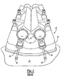
- the engine 20 includes an engine block 22 having a plurality of engine combustion chambers 24 in which pistons (not shown) are reciprocally mounted.
- At least one fuel injector 26 is associated with each combustion chamber 24.
- Each fuel injector 26 is positioned within a fuel injector bore 28 formed in the engine block 22 which is open to the combustion chambers 24.
- Each fuel injector 26, furthermore, is then fluidly coupled to a fuel rail 30 having an internal fuel chamber 32.
- a high pressure fuel pump (not shown) provides pressurized fuel to the fuel rail chambers 32 which, in turn, supply that pressurized fuel to the injectors 26.
- the fuel injectors illustrated in FIG. 1 are for a V engine in which two fuel rails 30 are positioned side by side each other.
- the fuel injectors 26 are rigidly secured to their associated fuel rail 30. Upon each injection of fuel, the fuel injector 26 moves slightly away from the combustion chamber 24 which causes a like movement in its associated fuel rail 30. Such movement of the fuel rail 30 In turn imparts mechanical stress on the fuel system components.
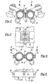
- a V-shaped clamp 40 extends between and is attached to each fuel rail 30 by fasteners 42 ( FIG. 3 ). Any conventional fastener 42 may be used to secure the clamp 40 to the fuel rails 30. Alternatively, the clamp 40 may be fixedly secured to the fuel rails 30 by welding or the like.
- a moving mass 44 is also secured to the clamp 40 by a resilient member or spring 46.
- the resilient member 46 allows the moving mass 44 to move relative to the clamp 40 and thus relative to the fuel rails 30.
- the moving mass 44 moves thus effectively canceling any movement of the fuel rails 30.
- the clamp 40 itself alone reduces movement of the fuel rails 30 during operation of the internal combustion engine.
- the moving mass 44 may also be used with a single fuel rail. In such a system, the moving mass 44 offsets or cancels movement of the fuel rail during operation of the engine.
- a clamp 50 extends around both fuel rails 30 and secures the fuel rails 30 together against movement.
- the clamp 50 may take any form, as shown the clamp 50 includes a top half 52 and a bottom half 54 which, together, encircle the fuel rails 30. These clamp halves 52 and 54 are secured together by fasteners 56 which may be any conventional fastener, such as a bolt and nut.
- the clamp 50 by rigidly securing the fuel rails 30 together, reduces movement of the fuel rails 30 and the resultant mechanical stress on the fuel system components from such movement.
- an elongated clamp 60 in the form of a strap has one end 62 rigidly secured to one fuel rail 30 in any conventional manner, such as by soldering.
- a second end 64 of the clamp 60 is then secured to the other fuel rail 30 by a fastener 66 which sandwiches an elastomeric resilient member 68 in between the fastener 66 and the fuel rail 30.
- the elastomeric dampener 68 dampens vibrations and movement of the fuel rails 30.
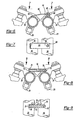
- an elongated resilient dampener 70 extends between the two fuel rails 30.
- a fastener 72 secures one end of the dampener 70 to one fuel rail 30 while a second fastener 74 secures the other end of the dampener 70 to the other fuel rail 30.
- the fastener 72 may comprise a bolt extending through the dampener 70 while the second fastener 74 is a nut that threadably engages the fastener 72.
- the fastener 72 also extends through a bolt stop 76 mounted to each fuel rail 30.
- the dampener 70 dampens vibrations of the fuel rails 30 in a lateral direction as indicated by arrows 78 in FIG. 9 .
- the dampener 70 effectively reduces movement of the fuel rall and likewise reduces component stress resulting from that movement.
- a clamp 80 having two clamp sections 82 and 84 is provided to minimize movement of the fuel rails 30.
- Each clamp section 82 and 84 includes a recess 86 which corresponds in shape to a portion of the ends 88 of the fuel rails 30.
- a fastener 90 secures the clamp sections 82 and 84 together while simultaneously compressing the clamp sections 82 and 84 around the ends 88 of the fuel rails 30. In doing so, the fuel rails 30 are rigidly secured together against movement thus reducing mechanical stress on the fuel system components.
- a still further embodiment of the present Invention is shown in which a generally V-shaped clamp 100 extends between and is secured to both fuel rails 30. Any conventional means, such as fasteners, solder or the like, may be used to secure the clamp 100 rigidly to the fuel rails 30.
- a resilient member 102 preferably constructed of an elastomeric material, is disposed across the top of the clamp 100.
- a moving mass 104 is then positioned within the resilient member 102 so that the resilient member 102 is sandwiched in between the moving mass 104 and the clamp 100.
- the resilient member 102 allows the moving mass 104 to move slightly relative to the fuel rails 30.
- the moving mass 104 by moving, dampens the movement of the rails 30 and reduces component stress.
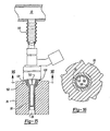
- the fuel injector 26 is fluidly connected to its associated fuel rail 30 by a flexible fluid conduit 110.
- the fluid conduit 110 may be in the shape of a flexible bellows although other shapes may alternatively be used.
- movement of the fuel injector 26 in response to a fuel injection by the injector 26 merely causes the fluid conduit 110 to flex, thus isolating any vibration of the fuel injector 26 from the fuel rail 30. in doing so, movement of the fuel rail 30 is greatly reduced, if not altogether eliminated, thus reducing mechanical stress caused by movement of the fuel rail 30.
- a locator 120 is externally threaded and includes a radially inwardly projecting tab 122.
- the locator 120 is preferably made of a non-metallic material to eliminate metal-to-metal contact between the injector 26 and the engine block 20 to dampen noise.
- the injector bore 28 includes an internally threaded portion 126 at its outer end. Consequently, by threadably securing the locator to the engine block 20, the locator 120 simply, but effectively, locks the fuel injector 26 against axial movement relative to the engine block.
- the fuel injector 26 can be made of a non-metallic material with the threads to engage the thread portion 126 on the engine block formed integrally on the fuel injector 26.
- the present invention provides several different devices for reducing, or altogether eliminating, movement of the fuel rail relative to the engine block. Stress on the fuel system components resulting from movement of the fuel rail relative to the engine block during operation of the internal combustion engine is substantially reduced.
Claims (2)
- Appareil pour réduire les contraintes mécaniques dans un système de distribution de carburant pour un moteur à combustion interne à injection directe (20) ayant un bloc-moteur (22) comprenant :une première rampe à carburant et une seconde rampe à carburant (30) montées respectivement sur le bloc-moteur (22),un dispositif qui réduit le mouvement de la première rampe et de la seconde rampe par rapport au bloc-moteur (22), caractérisé en ce que le dispositif comprend une pince en forme de V (40, 100) s'étendant entre et étant fixée rigidement à la première rampe à carburant et à la seconde rampe à carburant, une masse mobile (44, 104), et un élément élastique (46, 102) étant pris en sandwich entre la masse mobile et la pince).
- Appareil selon la revendication 1, dans lequel ladite pince (40 ; 100) est disposée autour d'une portion au moins des deux rampes à carburant (30).
Applications Claiming Priority (1)
| Application Number | Priority Date | Filing Date | Title |
|---|---|---|---|
| US12/414,151 US7980226B2 (en) | 2009-03-30 | 2009-03-30 | Fuel system for a direct injection engine |
Publications (3)
| Publication Number | Publication Date |
|---|---|
| EP2236808A2 EP2236808A2 (fr) | 2010-10-06 |
| EP2236808A3 EP2236808A3 (fr) | 2011-03-09 |
| EP2236808B1 true EP2236808B1 (fr) | 2014-11-12 |
Family
ID=42333447
Family Applications (1)
| Application Number | Title | Priority Date | Filing Date |
|---|---|---|---|
| EP10153878.3A Active EP2236808B1 (fr) | 2009-03-30 | 2010-02-17 | Kraftstoffsystem für einen Direkteinspritzmotor |
Country Status (4)
| Country | Link |
|---|---|
| US (1) | US7980226B2 (fr) |
| EP (1) | EP2236808B1 (fr) |
| JP (1) | JP5448872B2 (fr) |
| CN (1) | CN101852154B (fr) |
Families Citing this family (6)
| Publication number | Priority date | Publication date | Assignee | Title |
|---|---|---|---|---|
| DE102012206931A1 (de) * | 2012-04-26 | 2013-10-31 | Robert Bosch Gmbh | Anordnung mit einem Brennstoffverteiler und einem Halter |
| DE102012206937A1 (de) * | 2012-04-26 | 2013-10-31 | Robert Bosch Gmbh | Anordnung mit einem Brennstoffverteiler und einem Halter |
| US9644753B2 (en) | 2013-07-17 | 2017-05-09 | Norgren Limited | Flapper exhaust diverter valve |
| US10220700B2 (en) * | 2015-02-09 | 2019-03-05 | Toyota Motor Engineering & Manufacturing North America, Inc. | Protection and support for vehicle engine components |
| US10208723B2 (en) | 2016-05-25 | 2019-02-19 | Hi-Vol Products | Threaded fuel rails |
| CN107524520B (zh) * | 2017-08-18 | 2022-05-03 | 奇瑞汽车股份有限公司 | 喷油器的降噪结构 |
Family Cites Families (29)
| Publication number | Priority date | Publication date | Assignee | Title |
|---|---|---|---|---|
| JPS51146514U (fr) * | 1975-05-20 | 1976-11-25 | ||
| DE2829057A1 (de) * | 1978-07-01 | 1980-01-10 | Bosch Gmbh Robert | Kraftstoffeinspritzanlage |
| JPS6034562U (ja) * | 1983-08-17 | 1985-03-09 | 三菱重工業株式会社 | パイプクランプ |
| JPS63115572U (fr) * | 1987-01-21 | 1988-07-26 | ||
| US4766405A (en) * | 1987-04-14 | 1988-08-23 | Allied Corporation | Dynamic energy absorber |
| JPH0188065U (fr) * | 1987-12-03 | 1989-06-09 | ||
| US4878650A (en) * | 1988-04-29 | 1989-11-07 | Allied-Signal Inc. | Armature with shear stress damper |
| JPH01176750U (fr) * | 1988-06-02 | 1989-12-18 | ||
| DE4310408C1 (de) * | 1993-03-31 | 1994-06-09 | Freudenberg Carl Fa | Kraftstoffversorgung für eine mehrzylindrige Verbrennungskraftmaschine |
| JP4194002B2 (ja) * | 1998-05-13 | 2008-12-10 | ヤマハマリン株式会社 | 筒内燃料噴射式エンジン |
| US6009856A (en) | 1998-05-27 | 2000-01-04 | Caterpillar Inc. | Fuel injector isolation |
| US6409102B1 (en) * | 1999-03-15 | 2002-06-25 | Aerosance, Inc. | Fuel injector assembly |
| AT4632U1 (de) * | 2000-05-25 | 2001-09-25 | Avl List Gmbh | Einspritzsystem für eine brennkraftmaschine |
| JP4428607B2 (ja) * | 2000-10-25 | 2010-03-10 | 臼井国際産業株式会社 | コモンレール式ディーゼルエンジン用燃料噴射管 |
| JP4240835B2 (ja) * | 2001-03-29 | 2009-03-18 | 株式会社日本自動車部品総合研究所 | 内燃機関の燃料噴射装置 |
| US6901964B2 (en) | 2001-03-30 | 2005-06-07 | Saturn Electronics & Engineering, Inc. | Vehicle fuel pulse damper |
| JP4006956B2 (ja) * | 2001-05-24 | 2007-11-14 | 日産自動車株式会社 | V型エンジンの燃料配管構造 |
| DE10157010A1 (de) * | 2001-11-21 | 2003-06-05 | Bosch Gmbh Robert | Brennstoffeinspritzanlage |
| JP4152294B2 (ja) * | 2003-10-22 | 2008-09-17 | 臼井国際産業株式会社 | フューエルデリバリパイプ |
| FR2861433B1 (fr) * | 2003-10-24 | 2007-08-24 | Renault Sa | Dispositif d'injection en carburant sous pression comportant des moyens antivibratoires |
| FR2875863B1 (fr) * | 2004-09-30 | 2009-05-01 | Peugeot Citroen Automobiles Sa | Dispositif d'injection a rayonnement accoustique reduit |
| US7028688B1 (en) * | 2005-04-05 | 2006-04-18 | The United States Of America As Represented By The Secretary Of The Army | Operationally adaptable chemical-biological mask |
| DE102005029842A1 (de) * | 2005-06-27 | 2007-01-04 | Robert Bosch Gmbh | Kraftstoffspeicher eines Kraftstoff-Einspritzsystems eines Kraftfahrzeugs |
| US7293550B2 (en) | 2006-01-31 | 2007-11-13 | Gm Global Technology Operations, Inc. | Fuel injector isolation seat |
| ATE416308T1 (de) * | 2006-03-23 | 2008-12-15 | Delphi Tech Inc | Befestigungsanordnung für einen injektor |
| US7334571B1 (en) | 2006-08-31 | 2008-02-26 | Gm Global Technology Operations, Inc. | Isolation system for high pressure spark ignition direct injection fuel delivery components |
| FR2909420B1 (fr) * | 2006-11-30 | 2012-01-27 | Renault Sas | Barrette amortissant les vibrations de tuyaux d'injection sur un moteur a combustion interne |
| US7406946B1 (en) | 2007-04-02 | 2008-08-05 | Hitachi, Ltd. | Method and apparatus for attenuating fuel pump noise in a direct injection internal combustion chamber |
| US7793639B2 (en) * | 2008-09-25 | 2010-09-14 | Hitachi, Ltd. | Apparatus for reducing the transmission for noise from the fuel rail in a direct injection engine |
-
2009
- 2009-03-30 US US12/414,151 patent/US7980226B2/en active Active
-
2010
- 2010-01-21 JP JP2010010544A patent/JP5448872B2/ja active Active
- 2010-02-08 CN CN201010113789.3A patent/CN101852154B/zh active Active
- 2010-02-17 EP EP10153878.3A patent/EP2236808B1/fr active Active
Also Published As
| Publication number | Publication date |
|---|---|
| JP2010236535A (ja) | 2010-10-21 |
| CN101852154A (zh) | 2010-10-06 |
| EP2236808A2 (fr) | 2010-10-06 |
| EP2236808A3 (fr) | 2011-03-09 |
| CN101852154B (zh) | 2013-05-01 |
| JP5448872B2 (ja) | 2014-03-19 |
| US7980226B2 (en) | 2011-07-19 |
| US20100242916A1 (en) | 2010-09-30 |
Similar Documents
| Publication | Publication Date | Title |
|---|---|---|
| EP2236808B1 (fr) | Kraftstoffsystem für einen Direkteinspritzmotor | |
| US6276339B1 (en) | Fuel injector spring clip assembly | |
| US7793639B2 (en) | Apparatus for reducing the transmission for noise from the fuel rail in a direct injection engine | |
| US8087398B2 (en) | Fuel system for a direct injection internal combustion engine | |
| US20120204837A1 (en) | Fuel injector assembly | |
| US8499745B2 (en) | Fuel supply system of vee engine | |
| US10174734B2 (en) | Fuel-injection system having a fuel-conducting component, a fuel injector and a suspension mount | |
| US8844502B2 (en) | Fuel rail mount | |
| US20130104852A1 (en) | Fuel rail mounting arrangement | |
| US10132282B2 (en) | Fuel rail assembly | |
| US7469680B2 (en) | Fluid system having quill-mounted manifold | |
| EP3312408B1 (fr) | Structure de tuyau d'alimentation en carburant gdi | |
| KR102075333B1 (ko) | 내연기관에 부품을 고정하는 홀더 | |
| US9422903B2 (en) | Connecting element for GDI tube stress reduction | |
| US6644279B1 (en) | High pressure reservoir for fuel | |
| KR102074655B1 (ko) | 내연기관에 연료 분배기를 고정하기 위한 리테이너 및 상기 리테이너를 구비한 연료 분사 시스템 | |
| US10393080B2 (en) | Coupling device | |
| US8096277B2 (en) | Intake manifold for an internal combustion engine provided with metallic reinforcement brackets for fastening the fuel common rail | |
| US20130284152A1 (en) | System having a fuel distributor and a mounting support | |
| JP6194722B2 (ja) | エンジンの燃料噴射装置 | |
| JP2001221127A (ja) | 内燃機関の燃料噴射装置 | |
| JP7464809B2 (ja) | 燃料噴射システム | |
| JP7481606B2 (ja) | 燃料噴射システム | |
| JP7265959B2 (ja) | エンジン部品の取付構造 | |
| JP6466562B2 (ja) | 燃料噴射装置、吊り下げ部材、及びこれらを備えた燃料噴射システム |
Legal Events
| Date | Code | Title | Description |
|---|---|---|---|
| PUAI | Public reference made under article 153(3) epc to a published international application that has entered the european phase |
Free format text: ORIGINAL CODE: 0009012 |
|
| 17P | Request for examination filed |
Effective date: 20100331 |
|
| AK | Designated contracting states |
Kind code of ref document: A2 Designated state(s): AT BE BG CH CY CZ DE DK EE ES FI FR GB GR HR HU IE IS IT LI LT LU LV MC MK MT NL NO PL PT RO SE SI SK SM TR |
|
| AX | Request for extension of the european patent |
Extension state: AL BA RS |
|
| PUAL | Search report despatched |
Free format text: ORIGINAL CODE: 0009013 |
|
| AK | Designated contracting states |
Kind code of ref document: A3 Designated state(s): AT BE BG CH CY CZ DE DK EE ES FI FR GB GR HR HU IE IS IT LI LT LU LV MC MK MT NL NO PL PT RO SE SI SK SM TR |
|
| AX | Request for extension of the european patent |
Extension state: AL BA RS |
|
| 17Q | First examination report despatched |
Effective date: 20111109 |
|
| RIC1 | Information provided on ipc code assigned before grant |
Ipc: F02M 55/02 20060101AFI20140122BHEP Ipc: F02M 63/00 20060101ALN20140122BHEP Ipc: F02M 63/02 20060101ALI20140122BHEP |
|
| GRAP | Despatch of communication of intention to grant a patent |
Free format text: ORIGINAL CODE: EPIDOSNIGR1 |
|
| RIC1 | Information provided on ipc code assigned before grant |
Ipc: F02M 63/00 20060101ALN20140312BHEP Ipc: F02M 55/02 20060101AFI20140312BHEP Ipc: F02M 63/02 20060101ALI20140312BHEP |
|
| INTG | Intention to grant announced |
Effective date: 20140326 |
|
| GRAS | Grant fee paid |
Free format text: ORIGINAL CODE: EPIDOSNIGR3 |
|
| GRAA | (expected) grant |
Free format text: ORIGINAL CODE: 0009210 |
|
| RAP1 | Party data changed (applicant data changed or rights of an application transferred) |
Owner name: HITACHI, LTD. |
|
| AK | Designated contracting states |
Kind code of ref document: B1 Designated state(s): AT BE BG CH CY CZ DE DK EE ES FI FR GB GR HR HU IE IS IT LI LT LU LV MC MK MT NL NO PL PT RO SE SI SK SM TR |
|
| REG | Reference to a national code |
Ref country code: GB Ref legal event code: FG4D |
|
| REG | Reference to a national code |
Ref country code: CH Ref legal event code: EP |
|
| REG | Reference to a national code |
Ref country code: AT Ref legal event code: REF Ref document number: 695933 Country of ref document: AT Kind code of ref document: T Effective date: 20141115 |
|
| REG | Reference to a national code |
Ref country code: IE Ref legal event code: FG4D |
|
| REG | Reference to a national code |
Ref country code: DE Ref legal event code: R096 Ref document number: 602010020075 Country of ref document: DE Effective date: 20141224 |
|
| REG | Reference to a national code |
Ref country code: NL Ref legal event code: VDEP Effective date: 20141112 |
|
| REG | Reference to a national code |
Ref country code: AT Ref legal event code: MK05 Ref document number: 695933 Country of ref document: AT Kind code of ref document: T Effective date: 20141112 |
|
| PG25 | Lapsed in a contracting state [announced via postgrant information from national office to epo] |
Ref country code: IS Free format text: LAPSE BECAUSE OF FAILURE TO SUBMIT A TRANSLATION OF THE DESCRIPTION OR TO PAY THE FEE WITHIN THE PRESCRIBED TIME-LIMIT Effective date: 20150312 Ref country code: PT Free format text: LAPSE BECAUSE OF FAILURE TO SUBMIT A TRANSLATION OF THE DESCRIPTION OR TO PAY THE FEE WITHIN THE PRESCRIBED TIME-LIMIT Effective date: 20150312 Ref country code: ES Free format text: LAPSE BECAUSE OF FAILURE TO SUBMIT A TRANSLATION OF THE DESCRIPTION OR TO PAY THE FEE WITHIN THE PRESCRIBED TIME-LIMIT Effective date: 20141112 Ref country code: LT Free format text: LAPSE BECAUSE OF FAILURE TO SUBMIT A TRANSLATION OF THE DESCRIPTION OR TO PAY THE FEE WITHIN THE PRESCRIBED TIME-LIMIT Effective date: 20141112 Ref country code: FI Free format text: LAPSE BECAUSE OF FAILURE TO SUBMIT A TRANSLATION OF THE DESCRIPTION OR TO PAY THE FEE WITHIN THE PRESCRIBED TIME-LIMIT Effective date: 20141112 Ref country code: NO Free format text: LAPSE BECAUSE OF FAILURE TO SUBMIT A TRANSLATION OF THE DESCRIPTION OR TO PAY THE FEE WITHIN THE PRESCRIBED TIME-LIMIT Effective date: 20150212 Ref country code: NL Free format text: LAPSE BECAUSE OF FAILURE TO SUBMIT A TRANSLATION OF THE DESCRIPTION OR TO PAY THE FEE WITHIN THE PRESCRIBED TIME-LIMIT Effective date: 20141112 |
|
| PG25 | Lapsed in a contracting state [announced via postgrant information from national office to epo] |
Ref country code: SE Free format text: LAPSE BECAUSE OF FAILURE TO SUBMIT A TRANSLATION OF THE DESCRIPTION OR TO PAY THE FEE WITHIN THE PRESCRIBED TIME-LIMIT Effective date: 20141112 Ref country code: AT Free format text: LAPSE BECAUSE OF FAILURE TO SUBMIT A TRANSLATION OF THE DESCRIPTION OR TO PAY THE FEE WITHIN THE PRESCRIBED TIME-LIMIT Effective date: 20141112 Ref country code: PL Free format text: LAPSE BECAUSE OF FAILURE TO SUBMIT A TRANSLATION OF THE DESCRIPTION OR TO PAY THE FEE WITHIN THE PRESCRIBED TIME-LIMIT Effective date: 20141112 Ref country code: HR Free format text: LAPSE BECAUSE OF FAILURE TO SUBMIT A TRANSLATION OF THE DESCRIPTION OR TO PAY THE FEE WITHIN THE PRESCRIBED TIME-LIMIT Effective date: 20141112 Ref country code: CY Free format text: LAPSE BECAUSE OF FAILURE TO SUBMIT A TRANSLATION OF THE DESCRIPTION OR TO PAY THE FEE WITHIN THE PRESCRIBED TIME-LIMIT Effective date: 20141112 Ref country code: GR Free format text: LAPSE BECAUSE OF FAILURE TO SUBMIT A TRANSLATION OF THE DESCRIPTION OR TO PAY THE FEE WITHIN THE PRESCRIBED TIME-LIMIT Effective date: 20150213 Ref country code: LV Free format text: LAPSE BECAUSE OF FAILURE TO SUBMIT A TRANSLATION OF THE DESCRIPTION OR TO PAY THE FEE WITHIN THE PRESCRIBED TIME-LIMIT Effective date: 20141112 |
|
| PG25 | Lapsed in a contracting state [announced via postgrant information from national office to epo] |
Ref country code: RO Free format text: LAPSE BECAUSE OF FAILURE TO SUBMIT A TRANSLATION OF THE DESCRIPTION OR TO PAY THE FEE WITHIN THE PRESCRIBED TIME-LIMIT Effective date: 20141112 Ref country code: CZ Free format text: LAPSE BECAUSE OF FAILURE TO SUBMIT A TRANSLATION OF THE DESCRIPTION OR TO PAY THE FEE WITHIN THE PRESCRIBED TIME-LIMIT Effective date: 20141112 Ref country code: EE Free format text: LAPSE BECAUSE OF FAILURE TO SUBMIT A TRANSLATION OF THE DESCRIPTION OR TO PAY THE FEE WITHIN THE PRESCRIBED TIME-LIMIT Effective date: 20141112 Ref country code: DK Free format text: LAPSE BECAUSE OF FAILURE TO SUBMIT A TRANSLATION OF THE DESCRIPTION OR TO PAY THE FEE WITHIN THE PRESCRIBED TIME-LIMIT Effective date: 20141112 Ref country code: SK Free format text: LAPSE BECAUSE OF FAILURE TO SUBMIT A TRANSLATION OF THE DESCRIPTION OR TO PAY THE FEE WITHIN THE PRESCRIBED TIME-LIMIT Effective date: 20141112 |
|
| REG | Reference to a national code |
Ref country code: DE Ref legal event code: R097 Ref document number: 602010020075 Country of ref document: DE |
|
| PLBE | No opposition filed within time limit |
Free format text: ORIGINAL CODE: 0009261 |
|
| STAA | Information on the status of an ep patent application or granted ep patent |
Free format text: STATUS: NO OPPOSITION FILED WITHIN TIME LIMIT |
|
| PG25 | Lapsed in a contracting state [announced via postgrant information from national office to epo] |
Ref country code: LU Free format text: LAPSE BECAUSE OF FAILURE TO SUBMIT A TRANSLATION OF THE DESCRIPTION OR TO PAY THE FEE WITHIN THE PRESCRIBED TIME-LIMIT Effective date: 20150217 |
|
| REG | Reference to a national code |
Ref country code: CH Ref legal event code: PL |
|
| 26N | No opposition filed |
Effective date: 20150813 |
|
| GBPC | Gb: european patent ceased through non-payment of renewal fee |
Effective date: 20150217 |
|
| PG25 | Lapsed in a contracting state [announced via postgrant information from national office to epo] |
Ref country code: LI Free format text: LAPSE BECAUSE OF NON-PAYMENT OF DUE FEES Effective date: 20150228 Ref country code: CH Free format text: LAPSE BECAUSE OF NON-PAYMENT OF DUE FEES Effective date: 20150228 Ref country code: MC Free format text: LAPSE BECAUSE OF FAILURE TO SUBMIT A TRANSLATION OF THE DESCRIPTION OR TO PAY THE FEE WITHIN THE PRESCRIBED TIME-LIMIT Effective date: 20141112 |
|
| REG | Reference to a national code |
Ref country code: IE Ref legal event code: MM4A |
|
| REG | Reference to a national code |
Ref country code: FR Ref legal event code: ST Effective date: 20151030 |
|
| PG25 | Lapsed in a contracting state [announced via postgrant information from national office to epo] |
Ref country code: IT Free format text: LAPSE BECAUSE OF FAILURE TO SUBMIT A TRANSLATION OF THE DESCRIPTION OR TO PAY THE FEE WITHIN THE PRESCRIBED TIME-LIMIT Effective date: 20141112 |
|
| PG25 | Lapsed in a contracting state [announced via postgrant information from national office to epo] |
Ref country code: IE Free format text: LAPSE BECAUSE OF NON-PAYMENT OF DUE FEES Effective date: 20150217 Ref country code: GB Free format text: LAPSE BECAUSE OF NON-PAYMENT OF DUE FEES Effective date: 20150217 |
|
| PG25 | Lapsed in a contracting state [announced via postgrant information from national office to epo] |
Ref country code: SI Free format text: LAPSE BECAUSE OF FAILURE TO SUBMIT A TRANSLATION OF THE DESCRIPTION OR TO PAY THE FEE WITHIN THE PRESCRIBED TIME-LIMIT Effective date: 20141112 Ref country code: FR Free format text: LAPSE BECAUSE OF NON-PAYMENT OF DUE FEES Effective date: 20150302 |
|
| PG25 | Lapsed in a contracting state [announced via postgrant information from national office to epo] |
Ref country code: MT Free format text: LAPSE BECAUSE OF FAILURE TO SUBMIT A TRANSLATION OF THE DESCRIPTION OR TO PAY THE FEE WITHIN THE PRESCRIBED TIME-LIMIT Effective date: 20141112 |
|
| PG25 | Lapsed in a contracting state [announced via postgrant information from national office to epo] |
Ref country code: HU Free format text: LAPSE BECAUSE OF FAILURE TO SUBMIT A TRANSLATION OF THE DESCRIPTION OR TO PAY THE FEE WITHIN THE PRESCRIBED TIME-LIMIT; INVALID AB INITIO Effective date: 20100217 Ref country code: SM Free format text: LAPSE BECAUSE OF FAILURE TO SUBMIT A TRANSLATION OF THE DESCRIPTION OR TO PAY THE FEE WITHIN THE PRESCRIBED TIME-LIMIT Effective date: 20141112 Ref country code: BG Free format text: LAPSE BECAUSE OF FAILURE TO SUBMIT A TRANSLATION OF THE DESCRIPTION OR TO PAY THE FEE WITHIN THE PRESCRIBED TIME-LIMIT Effective date: 20141112 |
|
| PG25 | Lapsed in a contracting state [announced via postgrant information from national office to epo] |
Ref country code: TR Free format text: LAPSE BECAUSE OF FAILURE TO SUBMIT A TRANSLATION OF THE DESCRIPTION OR TO PAY THE FEE WITHIN THE PRESCRIBED TIME-LIMIT Effective date: 20141112 |
|
| PG25 | Lapsed in a contracting state [announced via postgrant information from national office to epo] |
Ref country code: BE Free format text: LAPSE BECAUSE OF FAILURE TO SUBMIT A TRANSLATION OF THE DESCRIPTION OR TO PAY THE FEE WITHIN THE PRESCRIBED TIME-LIMIT Effective date: 20141112 |
|
| PG25 | Lapsed in a contracting state [announced via postgrant information from national office to epo] |
Ref country code: MK Free format text: LAPSE BECAUSE OF FAILURE TO SUBMIT A TRANSLATION OF THE DESCRIPTION OR TO PAY THE FEE WITHIN THE PRESCRIBED TIME-LIMIT Effective date: 20141112 |
|
| PGFP | Annual fee paid to national office [announced via postgrant information from national office to epo] |
Ref country code: DE Payment date: 20231228 Year of fee payment: 15 |