EP2236764A2 - Düsenkasten für eine axial durchströmte Turbine und axial durchströmte Turbine - Google Patents
Düsenkasten für eine axial durchströmte Turbine und axial durchströmte Turbine Download PDFInfo
- Publication number
- EP2236764A2 EP2236764A2 EP10156203A EP10156203A EP2236764A2 EP 2236764 A2 EP2236764 A2 EP 2236764A2 EP 10156203 A EP10156203 A EP 10156203A EP 10156203 A EP10156203 A EP 10156203A EP 2236764 A2 EP2236764 A2 EP 2236764A2
- Authority
- EP
- European Patent Office
- Prior art keywords
- channel
- pipe
- steam
- axial flow
- nozzle box
- Prior art date
- Legal status (The legal status is an assumption and is not a legal conclusion. Google has not performed a legal analysis and makes no representation as to the accuracy of the status listed.)
- Granted
Links
Images




Classifications
-
- F—MECHANICAL ENGINEERING; LIGHTING; HEATING; WEAPONS; BLASTING
- F01—MACHINES OR ENGINES IN GENERAL; ENGINE PLANTS IN GENERAL; STEAM ENGINES
- F01D—NON-POSITIVE DISPLACEMENT MACHINES OR ENGINES, e.g. STEAM TURBINES
- F01D9/00—Stators
- F01D9/02—Nozzles; Nozzle boxes; Stator blades; Guide conduits, e.g. individual nozzles
- F01D9/04—Nozzles; Nozzle boxes; Stator blades; Guide conduits, e.g. individual nozzles forming ring or sector
- F01D9/047—Nozzle boxes
-
- F—MECHANICAL ENGINEERING; LIGHTING; HEATING; WEAPONS; BLASTING
- F01—MACHINES OR ENGINES IN GENERAL; ENGINE PLANTS IN GENERAL; STEAM ENGINES
- F01D—NON-POSITIVE DISPLACEMENT MACHINES OR ENGINES, e.g. STEAM TURBINES
- F01D25/00—Component parts, details, or accessories, not provided for in, or of interest apart from, other groups
- F01D25/24—Casings; Casing parts, e.g. diaphragms, casing fastenings
- F01D25/26—Double casings; Measures against temperature strain in casings
-
- F—MECHANICAL ENGINEERING; LIGHTING; HEATING; WEAPONS; BLASTING
- F01—MACHINES OR ENGINES IN GENERAL; ENGINE PLANTS IN GENERAL; STEAM ENGINES
- F01D—NON-POSITIVE DISPLACEMENT MACHINES OR ENGINES, e.g. STEAM TURBINES
- F01D9/00—Stators
- F01D9/06—Fluid supply conduits to nozzles or the like
-
- F—MECHANICAL ENGINEERING; LIGHTING; HEATING; WEAPONS; BLASTING
- F05—INDEXING SCHEMES RELATING TO ENGINES OR PUMPS IN VARIOUS SUBCLASSES OF CLASSES F01-F04
- F05D—INDEXING SCHEME FOR ASPECTS RELATING TO NON-POSITIVE-DISPLACEMENT MACHINES OR ENGINES, GAS-TURBINES OR JET-PROPULSION PLANTS
- F05D2210/00—Working fluids
- F05D2210/40—Flow geometry or direction
- F05D2210/43—Radial inlet and axial outlet
-
- F—MECHANICAL ENGINEERING; LIGHTING; HEATING; WEAPONS; BLASTING
- F05—INDEXING SCHEMES RELATING TO ENGINES OR PUMPS IN VARIOUS SUBCLASSES OF CLASSES F01-F04
- F05D—INDEXING SCHEME FOR ASPECTS RELATING TO NON-POSITIVE-DISPLACEMENT MACHINES OR ENGINES, GAS-TURBINES OR JET-PROPULSION PLANTS
- F05D2240/00—Components
- F05D2240/10—Stators
- F05D2240/12—Fluid guiding means, e.g. vanes
- F05D2240/128—Nozzles
-
- F—MECHANICAL ENGINEERING; LIGHTING; HEATING; WEAPONS; BLASTING
- F05—INDEXING SCHEMES RELATING TO ENGINES OR PUMPS IN VARIOUS SUBCLASSES OF CLASSES F01-F04
- F05D—INDEXING SCHEME FOR ASPECTS RELATING TO NON-POSITIVE-DISPLACEMENT MACHINES OR ENGINES, GAS-TURBINES OR JET-PROPULSION PLANTS
- F05D2250/00—Geometry
- F05D2250/20—Three-dimensional
Definitions
- the present invention relates to a nozzle box that constitutes a channel of a working fluid leading the working fluid to a first-stage nozzle of an axial flow turbine, and to an axial flow turbine including the nozzle box.
- An axial flow rotary machine such as a steam turbine used in a thermal power station and the like includes blade cascades composed of a plurality of stages of the combination of a nozzle whose channel for the passage of a working fluid is stationary and a rotor blade which rotates.
- a steam turbine is generally divided into a high-pressure part, an intermediate-pressure part, and a low-pressure part depending on a condition of steam being a working fluid.
- channels between the blade cascades have to be designed in a shape allowing smooth flow of the working fluid.
- the internal losses in a steam turbine blade cascade of a steam turbine include a profile loss ascribable to the shape of blades, a secondary loss ascribable to a secondary flow, a leakage loss ascribable to leakage of a working fluid to the outside of a blade cascade, and a moisture loss ascribable to drain, which is unique to a final blade group.
- the internal losses further include a loss in a steam valve, a passage part leading steam to some blade cascade, and a passage part from some blade cascade up to the next blade cascade, an exhaust loss in a low-pressure final stage, and so on.
- JP-A 2008-38741 discloses an art to uniformly lead a working fluid to a blade cascade in order to reduce a pressure loss in a passage part connecting some blade cascade and another blade cascade.
- the width of the passage part through which the working fluid passes is monotonously increased toward a downstream side.
- FIG. 9 is a perspective view showing part of the conventional nozzle box 300.
- FIG. 10 is a view showing the conventional nozzle box 300 in its cross section vertical to a turbine rotor seen from a first-stage nozzle 303 side.
- FIG. 11 is a view showing a cross section of the conventional nozzle box 300 taken along a channel center line. The illustration of the turbine rotor, which is penetratingly provided at the center of the nozzle box 300, is omitted here.
- the nozzle box 300 is a structure forming a steam channel through which steam led into lead-in pipes 302 passes to be led into a first-stage nozzle 303.
- the nozzle box 300 is separated into two upper and lower spaces, and steam 301 from a boiler (not shown) is led into each of the spaces through the two lead-in pipes 302.
- the steam 301 led into the lead-in pipes 302 made of a cylindrical pipe is led to the first-stage nozzle 303 through an annular channel 304.
- the whole periphery of the passage part is coupled, and the steam 301 having passed through the first-stage nozzle 303 is led to a first-stnge rotor blade (not shown).
- Sa-1 to Sn-1 shown in FIG. 10 each are a steam channel width in a first direction intersecting with a channel center line 305 at a predetermined position of a steam channel formed by the nozzle box 300.
- Sa-2 to Sn-2 shown in FIG. 11 each are a steam channel width in a second direction intersecting with the channel center line 305 and perpendicular to the first direction.
- the steam channel width in the first direction and the steam channel width in the second direction exist on the same channel cross section perpendicularly intersecting with the channel center line 305 of the steam channel.
- the steam channel width in the first direction is a steam channel width in a longitudinal direction on the channel cross section. That is, the steam channel width in the first direction is the largest channel width on this channel cross section.
- a cross sectional shape of the steam channel is circular. Therefore, the steam channel width in the first direction and the steam channel width in the second direction are equal to each other.
- a steam channel width in a direction corresponding to a steam channel width in the longitudinal direction of a channel cross section which is on a downstream side of the cross section where the cross sectional shape of the steam channel is circular and thus the steam channel width in the first direction and the steam channel width in the second direction are different from each other is set as Sa-1.
- the steam channel width in the first direction intersecting with the channel center line 305 at an outlet of the nozzle box 300, that is, at an inlet of the first-stage nozzle 303 is shown as Sn-1
- the steam channel width in the second direction intersecting with the channel center line 305 and perpendicular to this first direction is shown as Sn-2.
- the steam channel width Sa-1 and the steam channel width Sb-1 in each of the lead-in pipes 302 are equal to each other, but the steam channel width begins to widen from the steam channel width Sc-1 near a joint portion between the lead-in pipe 302 and the annular channel 304.
- the steam channel widths Sd-1, Se-1 in the annular channel 304 greatly widen further.
- the steam channel width Sa-2 to the steam channel width Sc-2 in the lead-in pipe 302 are equal to one another, but the steam channel width gets gradually narrower from me steam channel width Sd-2. Then, the steam channel width Sn-2 at the inlet of the first-stage nozzle 303 is equal to the height of the first-stage nozzle 303.
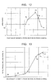
- FIG. 12 is a graph showing area ratios equal to areas of channel cross sections Sa to Sn which include the steam channel widths Sa-1 to Sn-1, Sa-2 to Sn-2 shown in FIG. 10 and FIG. 11 and perpendicularly intersect with the charnel center line 305 of me steam channel, divided by an area of the channel cross section Sa which is at the inlet of the lead-in pipe and which includes the steam channel widths Sa-1 and the seam channel width Sa-2 and perpendicularly intersects with the channel center line 305 of the steam channel. Note that FIG. 12 also shows area ratios in channel cross sections other than the channel cross sections Sa to Sn.
- the area ratios of the channel cross sections up to a channel cross section slightly on an upstream side of the channel cross section Sc have a constant value of 1 since they are channel cross sections of the aforesaid lead-in pipe 302.
- the area ratio abruptly increases.
- the area ratio presents a peak in the channel cross section Sd, and the area ratio abruptly decreases in the channel cross section on a downstream side of the channel cross section Sd.
- FIG. 13 is a graph showing a total pressure loss ratio in each of the channel cross sections shown in FIG. 12 .
- the total pressure loss ratio is expressed by the following expression (1), where Pa is a total pressure in the channel cross section Sa at the inlet of the steam channel formed by the nozzle box 300 and Po is a total pressure in a given channel cross section.
- total pressure loss ratio % Pa ⁇ Po / Pa ⁇ 100
- the total pressure loss ratio abruptly increases from the channel cross section slightly on the upstream side of the channel cross section Sc. This is a pressure loss that occurs because, from the channel cross section slightly on the upstream side of the channel cross section Sc, the steam channel width abruptly increases and thus the area ratio abruptly increases as shown in FIG. 12 .
- the conventional nozzle box 300 in the axial flow turbine has the problem that the abrupt increase in the area ratio due to the abrupt increase in the steam channel width causes a great pressure loss. This lowers turbine efficiency of the axial flow turbine and thus makes it difficult to obtain high turbine efficiency.
- a nozzle box of an axial flow turbine which formes a working fluid channel leading a working fluid to a first-stage nozzle of the axial flow turbine
- the nozzle box including: a lead-in pipe into which the working fluid is led; a bent pipe connected to the lead-in pipe and formed so as to change a direction of a channel center line to an axial direction of a turbine rotor of the axial flow turbine; and an annular pipe connected to the bent pipe, covering the turbine rotor from an outer peripheral side of the turbine rotor, and forming an annular passage leading the working fluid to the first-stage nozzle while spreading the working fluid in a circumferential direction of the turbine rotor, wherein, in the working fluid channel composed of the lead-in pipe, the bent pipe, and the annular pipe, from an inlet of the lead-in pipe toward an outlet of the annular pipe, a channel width in a first direction intersecting with the channel center line gradually increases and a channel width in a second
- an axial flow turbine in which a led-in working fluid is led to a first-stage nozzle via a working fluid channel, wherein the wording fluid channel is composed of the above-described nozzle box of the axial flow turbine.
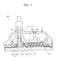
- FIG. 1 is a view showing a cross section in an upper half casing part of a steam turbine including a nozzle box according to the present invention.
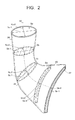
- FIG. 2 is a perspective view showing part of the nozzle box of one embodiment according to the present invention.
- FIG. 3 is a view showing the nozzle box of the embodiment according to the present invention in its cross section vertical to a turbine rotor seen from a first-stage nozzle side.
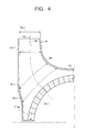
- FIG. 4 is a partial enlarged view showing the nozzle box of the embodiment according to the present invention in its cross section vertical to the turbine rotor seen from the first-stage nozzle side.
- FIG. 5 is a view showing a cross section taken along a channel center line of the nozzle box of the embodiment according to the present invention.
- FIG. 6 is a view showing a channel cross section in which a steam channel width in a first direction and a steam channel width in a second direction are different from each other and which includes a steam channel width Sb-1 and a steam channel width Sb-2.
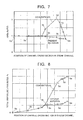
- FIG. 7 is a graph showing area ratios equal to areas of channel cross sections Sa to Sn which include steam channel widths Sa-1 to Sn-1, Sa-2 to Sn-2 shown in FIG. 2 to FIG. 5 and perpendicularly intersect with the channel center line of a steam channel, divided by an area of a charnel cross section Sa which is at an inlet of a lead-in pipe and which includes the steam channel width Sa-1 and the steam channel width Sa-2 and perpendicularly intersects with the channel center line of the steam channel.
- FIG. 8 is a graph showing total pressure loss ratios in the channel cross sections shown in FIG. 7 .
- FIG. 9 is a perspective view showing part of a conventional nozzle box.
- FIG. 10 is a view showing the conventional nozzle box in its cross section vertical to a turbine rotor seen from a first-stage nozzle side.
- FIG. 11 is a view showing a cross section of the conventional nozzle box taken along a channel center line.
- FIG. 12 is a graph showing area ratios equal to areas of channel cross sections Sa to Sn which include steam channel widths Sa-1 to Sn-1, Sa-2 to Sn-2 shown in FIG. 10 and FIG. 11 and perpendicularly intersect with the channel center line of a steam channel, divided by an area of a channel cross section Sa which is at an inlet of a lead-in pipe and which includes the steam channel width Sa-1 and the steam channel width Sa-2 and perpendicularly intersects with the channel center line of the steam channel.
- FIG. 13 is a graph showing total pressure loss ratios in the channel cross sections shown in FIG. 12 .
- FIG. 1 is a view showing a cross section in an upper half casing part of a steam turbine 200 including a nozzle box 10 according to the present invention.
- the steam turbine 200 functioning as an axial flow turbine includes, for example, a double-structure casing composed of an inner casing 210 and an outer casing 211 provided outside the inner casing 210. Further, a turbine rotor 212 is penetratingly provided in the inner casing 210. Further, on an inner surface of the inner casing 210, nozzles 213 are disposed, and in the turbine rotor 212, rotor blades 214 are implanted.
- the steam turbine 200 further includes the nozzle box 10.
- the nozzle box 10 is a steam channel leading steam, which is a working fluid led into the steam turbine 200, to a first-stage nozzle 213a.
- the nozzle box 10 constitutes a steam inlet of the steam turbine 200.
- the nozzle box 10 includes: a lead-in pipe 20 provided at an end portion of a steam inlet pipe 220 which is provided to penetrate through the outer casing 211 and the inner casing 210; a befit pipe 30 connected to the lead-in pipe 20 and formed so as to change a direction of a channel center line 50 to a direction along a center axis of the turbine rotor 212 of the steam turbine 200; and an annular pipe 40 connected to the bent pipe 30, covering the turbine rotor 212 from an outer peripheral side of the turbine rotor 212, and forming an annular passage leading the steam to the first-stage nozzle 213a while spreading the steam in a circumferential direction of the turbine rotor 212.
- the pipes forming the nozzle box 10 will be described in detail later.
- the steam flowing into the steam channel formed by the nozzle box 10 passes through the lead-in pipe 20, the bent pipe 30, and the annular pipe 40 to be led to the first-stage nozzle 213a.
- the whole periphery of the passage part is coupled on a downstream side of the first-stage nozzle 213a, and the steam led to the first-stage nozzle 213a is ejected toward a fust-stage rotor blade 214a.
- the ejected steam passes through steam passages between the nozzles 213 and the rotor blades 214 of respective stages to rotate the turbine rotor 212.
- most of the steam having performed expansion work is discharged and passes through, for example, a low-temperature reheating pipe (not shown) to flow into a boiler (not shown). Further, part of the steam having performed the expansion work is led, for example, as cooling steam to an area between the inner casing 210 and the outer casing 211 to be discharged from a ground part or from a discharge route through which most of the steam having performed the expansion work is discharged.
- the steam turbine 200 is not limited to that having the above-described structure, but it may be any steam turbine having the structure in which steam is led and the steam passes through steam passages between nozzles and rotor blades of respective stages to rotate a turbine rotor.
- FIG. 2 is a perspective view showing part of the nozzle box 10 of the embodiment according to the present invention.
- FIG. 3 is a view showing the nozzle box 10 of the embodiment according to the present invention in its cross section vertical to the turbine rotor 212 seen from the first-stage nozzle 213a side.
- FIG. 4 is a partial enlarged view showing the nozzle box 10 of the embodiment according to the present invention in its cross section vertical to the turbine rotor 212 seen from the first-stage nozzles 213a side.
- FIG. 5 is a view showing a cross section taken along the channel center line of the nozzle box 10 of the embodiment according to the present invention. Note that the illustration of the turbine rotor 212, which is penetratingly provided at the center of the nozzle box 10, is omitted in FIG. 2 to FIG. 5 .
- the nozzle box 10 is a structure forming the steam channel through which the steam led into the lead-in pipe 20 passes to be led into the fust-stage nozzle 213a.
- the nozzle box 10 is divided into, for example, two upper and lower spaces.
- two pairs of pipes into which the steam 60 from the boiler (not shown) is led are provided, each of the pairs being composed of a tead-in pipe 20 and a bent pipe 30.
- the nozzle box 10 further includes: the lead-in pipe 20 provided at the end portion of the steam inlet pipe 220 and into which the steam is led; the bent pipe 30 connected to the lead-in pipe 20 and formed so as to change the direction of the channel center line 50 to the direction along the center axis of the turbine rotor 212 of the steam turbine 200; and the annular pipe 40 connected to the bent pipe 30, covering the turbine rotor 212 from the outer peripheral side of the turbine rotor 212, and forming the annular passage leading the steam to the first-stage nozzle 213a a while spreading the steam in the circumferential direction of the turbine rotor 212.
- the lead-in pipe 20 may be provided so as to be connected to the end portion of the steam inlet pipe 220, or the structure of the end portion of the steam inlet pipe 220 may be the structure as the lead-in pipe 20.
- the steam inlet pipe 220 and the lead-in pipe 20 can be integrally structured. Since the lead-in pipe 20 is formed in this manner, the lead-in pipe 20 forms the steam channel in an extending direction of the steam inlet pipe 220, in other words, in a direction perpendicular to a horizontal plane along the center axis of the turbine rotor 212.
- the bent pipe 30 may be any provide that it changes even slightly the aforesaid direction of the channel center line 50 extending from the lead-in pipe 20, which direction is perpendicular to the horizontal plane along the center axis of the turbine rotor 212, to the axial direction of the turbine rotor 212. That is, it is only necessary that at an outlet of the bent pipe 30, the direction of the channel center line 50 is changed to the axial direction of the turbine rotor 212.
- the change to the axial direction of the turbine rotor 212 does not necessarily mean that the direction of the channel center line 50 at the outlet of the bent pipe 30 is horizontal to the horizontal plane along the center axis of the turbine rotor 212 and is changed to the axial direction of the turbine rotor 212.
- this change may also include a case where the direction of the channel center line 50 at the outlet of the bent pipe 30 has a predetermined angle to the horizontal surface along the center axis of the turbine rotor 212 and is changed to the axial direction of the turbine rotor 212.
- the steam channel formed by the lead-in pipe 20, the bent pipe 30, and the annular pipe 40 is formed such that, from the inlet of the lead-in pipe 20 toward the outlet of the annular pipe 40 (an inlet of the first-stage nozzle 213a), steam channel widths Sa-1 to Sn-1 in a first direction intersecting with the channel center line 50 gradually increases and steam channel widths Sa-2 to Sn-2 in a second direction which intersects with the channel center line 50 and is perpendicular to the first direction gradually decreases.
- the steam channel width at the outlet of the annular pipe 40 that is, at the inlet of the first-stage nozzle 213a, in the first direction intersecting with the channel center line 50 is shown as Sn-1, and a steam channel width in the second direction intersecting with the channel center line 50 and perpendicular to this first direction is shown as Sn-2. Further, the steam channel width Sn-2 at the outlet of the annular pipe 40 is equal to the height of the first-stage nozzle 213a.
- the steam channel widths Sa-1 to Sn-1 in the first direction and the steam channel widths Sa-2 to Sn-2 in the second direction exist on the same channel cross sections perpendicularly intersecting with the channel center line 50 of the steam channel, and when the steam channel width in the first direction and the steam channel width in the second direction are different from each other, the steam channel width in the first direction is a steam channel width in a longitudinal direction on this channel cross section. That is, the steam channel width in the first direction is the largest channel width on this channel cross section.
- FIG. 6 is a view showing a channel cross section where the steam channel width in the first direction and the steam channel width in the second direction are different from each other and which includes the steam channel width Sb-1 and the steam channel width Sb-2.
- the steam channel width in the longitudinal direction intersecting with the channel center line 50 on the channel cross section is defined as the steam channel width Sb-1 in the first direction.
- the steam channel width in the first direction and the steam channel width in the second direction are equal to each other.
- the steam channel width in a direction corresponding to the steam channel width in the longitudinal direction of a channel cross section witch is on a downstream side of the cross section where the cross sectional shape of the steam channel is circular and thus the steam channel width in the first direction and the steam channel width in the second direction are different from each other is set as Sa-1.
- areas of the channel cross sections Sa to Sn including the steam channel widths Sa-1 to Sn-1 in the first direction and the steam channel widths Sa-2 to Sn-2 in the second direction respectively monotonously change from the inlet of the lead-in pipe 20 toward the outlet of the annular pipe 40.
- the areas of the channel cross sections Sa to Sn including the steam channel widths Sa-1 to Sn-1 in the first direction and the steam channel widths Sa-2 to Sn-2 in the second direction respectively may monotonously decrease or may monotonously increase from the inlet of the lead-in pipe 20 toward the outlet of the annular pipe 40.
- the steam channel width in the first direction at a position near the first-stage nozzle 213a represents a channel width in a 1/4 range demarcated by center sectional lines of the nozzle box 10 which is vertically and laterally symmetrical, that is, demarcated by a center line connecting 0° and 180° and a center line connecting 90° and 270° in FIG. 3 .
- FIG. 7 is an example of a graph showing area ratios equal to areas of the channel cross sections Sa to Sn which include the steam channel widths Sa-1 to Sn-1, Sa-2 to Sn-2 shown in FIG. 2 to FIG. 5 and perpendicularly intersect with the channel center line 50 of the steam channel, divided by an area of the channel cross section Sa which is at the inlet of the lead-in pipe 20 and which includes the steam channel width Sa-1 and the steam channel width Sa-2 and perpendicularly intersects with the channel center line 50.
- FIG. 7 also shows area ratios in channel cross sections other than the area ratios in the channel cross sections Sa to Sn. Further, FIG. 7 also shows, for comparison, area ratios in the conventional nozzle box 300 shown in FIG. 12 .
- positions of the channel cross sections Sa to Sn in the steam channel that is, lengths along the channel center line 50 from the inlet of the nozzle box 10 up to the channel cross sections Sa to Sn in the nozzle box 10 of the embodiment correspond to those in the conventional nozzle box 300.
- the area ratio monotonously decreases from the inlet of the lead-in pipe 20 toward the outlet of the annular pipe 40.
- the change in the area ratio in the nozzle box 10 of the embodiment is a monotonous change compared with the change in the area ratio in the conventional nozzle box 300.
- the channel cross section Sa and the channel cross section Sn are determined by a design condition of the steam turbine, and it sometimes depends on the type of the steam turbine whether a ratio of the area of the channel cross section Sn and the area of the channel cross section Sa (area of the channel cross section Sn/area of the channel cross section Sa) is larger or smaller than 1, but the change in the area ratio is desirably a monotonous change as shown in FIG. 7 . This is because an abrupt area change causes a great change in the flow, whichever of an increasing change and a decreasing change the area change is, and the occurrence of swirl and the local occurrence of high speed area cause a great loss.
- FIG. 8 is a graph showing a total pressure loss ratio in each of the channel cross sections shown in FIG. 7 . Note that FIG. 8 also shows, for comparison, total pressure loss ratios in the conventional nozzle box 300 shown in FIG. 13 .
- the total pressure loss ratio is expressed by the aforesaid expression (1), where Pa is a total pressure at the inlet of the steam channel formed by the nozzle box 10, that is, in the channel cross section Sa at the inlet of the lead-in pipe 20, and Po is a total pressure in a given channel cross section.
- the total pressure loss ratios are obtained by three-dimensional thermal-fluid analysis in a steady state by using a CFD (Computational Fluid Dynamics).
- the total pressure loss ratio in the nozzle box 10 of the embodiment increases, but is lower than 1/3 of the total pressure loss ratios in the conventional nozzle box 300.
- the steam channel widths Sa-1 to Sn-1 in the first direction intersecting with the channel center line 50 are gradually increased, and the steam channel widths Sa-2 to Sn-2 in the second direction which intersects with the channel center line 50 and is perpendicular to the first direction are gradually decreased. Accordingly, the change in the channel cross section from the inlet of the lead-in pipe 20 toward the outlet of the annular pipe 40 is monotonous.
- the present invention is concretely described by the embodiment, but the present invention is not limited only to the embodiment and the embodiment can be variously modified within a range not departing from the spirit of the invention.
- the nozzle box 10 of the embodiment is applicable to an inlet part structure of each of a high-pressure part, an intermediate-pressure part, and a low-pressure part of the steam turbine.
Landscapes
- Engineering & Computer Science (AREA)
- Mechanical Engineering (AREA)
- General Engineering & Computer Science (AREA)
- Turbine Rotor Nozzle Sealing (AREA)
Applications Claiming Priority (1)
| Application Number | Priority Date | Filing Date | Title |
|---|---|---|---|
| JP2009062048A JP4869370B2 (ja) | 2009-03-13 | 2009-03-13 | 軸流タービンの蒸気導入部構造体および軸流タービン |
Publications (3)
| Publication Number | Publication Date |
|---|---|
| EP2236764A2 true EP2236764A2 (de) | 2010-10-06 |
| EP2236764A3 EP2236764A3 (de) | 2011-12-07 |
| EP2236764B1 EP2236764B1 (de) | 2020-01-22 |
Family
ID=42270249
Family Applications (1)
| Application Number | Title | Priority Date | Filing Date |
|---|---|---|---|
| EP10156203.1A Active EP2236764B1 (de) | 2009-03-13 | 2010-03-11 | Düsenkasten für eine axial durchströmte Turbine und axial durchströmte Turbine |
Country Status (4)
| Country | Link |
|---|---|
| US (1) | US8690532B2 (de) |
| EP (1) | EP2236764B1 (de) |
| JP (1) | JP4869370B2 (de) |
| CN (1) | CN101832155B (de) |
Cited By (2)
| Publication number | Priority date | Publication date | Assignee | Title |
|---|---|---|---|---|
| US9334744B2 (en) | 2010-07-14 | 2016-05-10 | Isis Innovation Ltd | Vane assembly for an axial flow turbine |
| EP3929409A1 (de) * | 2020-06-24 | 2021-12-29 | Siemens Aktiengesellschaft | Düsengehäuse für eine dampfturbine mit vier kammern und zwei steuerrädern |
Families Citing this family (3)
| Publication number | Priority date | Publication date | Assignee | Title |
|---|---|---|---|---|
| DE102010042412A1 (de) * | 2010-10-13 | 2012-04-19 | Robert Bosch Gmbh | Dampfturbine |
| JP5674521B2 (ja) * | 2011-03-25 | 2015-02-25 | 株式会社東芝 | 蒸気弁装置および蒸気タービンプラント |
| EP3023593A1 (de) * | 2014-11-20 | 2016-05-25 | Siemens Aktiengesellschaft | Einströmungskontur für Einwellenanordnung |
Citations (1)
| Publication number | Priority date | Publication date | Assignee | Title |
|---|---|---|---|---|
| JP2008038741A (ja) | 2006-08-04 | 2008-02-21 | Hitachi Ltd | 軸流タービン及びその入口構造 |
Family Cites Families (13)
| Publication number | Priority date | Publication date | Assignee | Title |
|---|---|---|---|---|
| BE456294A (de) | ||||
| US2526281A (en) * | 1947-04-10 | 1950-10-17 | Wright Aeronautical Corp | Turbine and turbine nozzle construction |
| US2527446A (en) * | 1948-09-17 | 1950-10-24 | Westinghouse Electric Corp | Turbine apparatus |
| US3371480A (en) * | 1966-06-16 | 1968-03-05 | United Aircraft Corp | One and one-half stage split turbine construction |
| CA1155766A (en) * | 1981-07-10 | 1983-10-25 | Hitachi, Ltd. | Turbine blades |
| JPS58202301A (ja) * | 1982-05-19 | 1983-11-25 | Hitachi Ltd | 蒸気タ−ビンロ−タ冷却装置 |
| JPS6069212A (ja) | 1983-09-26 | 1985-04-19 | Mitsubishi Heavy Ind Ltd | 蒸気タ−ビン用ノズルボックスの製造方法 |
| JPS62158132A (ja) * | 1986-01-03 | 1987-07-14 | オウエンス コ−ニング ファイバ−グラス コ−ポレ−ション | ストランド撚り装置および方法 |
| US6631858B1 (en) * | 2002-05-17 | 2003-10-14 | General Electric Company | Two-piece steam turbine nozzle box featuring a 360-degree discharge nozzle |
| JP2006016976A (ja) * | 2004-06-30 | 2006-01-19 | Toshiba Corp | タービンノズル支持装置および蒸気タービン |
| DE102005025213B4 (de) * | 2005-06-01 | 2014-05-15 | Honda Motor Co., Ltd. | Schaufel einer Axialströmungsmaschine |
| US7713023B2 (en) * | 2006-09-06 | 2010-05-11 | General Electric Company | Steam turbine nozzle box and methods of fabricating |
| JP2009047123A (ja) * | 2007-08-22 | 2009-03-05 | Toshiba Corp | 蒸気タービン |
-
2009
- 2009-03-13 JP JP2009062048A patent/JP4869370B2/ja not_active Expired - Fee Related
-
2010
- 2010-03-01 US US12/714,948 patent/US8690532B2/en not_active Expired - Fee Related
- 2010-03-11 EP EP10156203.1A patent/EP2236764B1/de active Active
- 2010-03-12 CN CN2010101330797A patent/CN101832155B/zh not_active Expired - Fee Related
Patent Citations (1)
| Publication number | Priority date | Publication date | Assignee | Title |
|---|---|---|---|---|
| JP2008038741A (ja) | 2006-08-04 | 2008-02-21 | Hitachi Ltd | 軸流タービン及びその入口構造 |
Cited By (3)
| Publication number | Priority date | Publication date | Assignee | Title |
|---|---|---|---|---|
| US9334744B2 (en) | 2010-07-14 | 2016-05-10 | Isis Innovation Ltd | Vane assembly for an axial flow turbine |
| EP3929409A1 (de) * | 2020-06-24 | 2021-12-29 | Siemens Aktiengesellschaft | Düsengehäuse für eine dampfturbine mit vier kammern und zwei steuerrädern |
| WO2021259571A1 (en) * | 2020-06-24 | 2021-12-30 | Siemens Aktiengesellschaft | Nozzle casing for a steam turbine with four chambers and two control wheels |
Also Published As
| Publication number | Publication date |
|---|---|
| JP2010216313A (ja) | 2010-09-30 |
| US8690532B2 (en) | 2014-04-08 |
| EP2236764A3 (de) | 2011-12-07 |
| CN101832155A (zh) | 2010-09-15 |
| CN101832155B (zh) | 2013-07-17 |
| EP2236764B1 (de) | 2020-01-22 |
| US20100232958A1 (en) | 2010-09-16 |
| JP4869370B2 (ja) | 2012-02-08 |
Similar Documents
| Publication | Publication Date | Title |
|---|---|---|
| EP2660427B1 (de) | Turbinensystem mit einem Uebergangskanal mit einer Balgdichtung | |
| EP1178182A1 (de) | Geteilter gasturbinenring | |
| EP2631436A2 (de) | Dampfturbine | |
| JP6847673B2 (ja) | タービン排気室 | |
| EP2236764B1 (de) | Düsenkasten für eine axial durchströmte Turbine und axial durchströmte Turbine | |
| CN112377268B (zh) | 一种增材制造的一体式扩压器 | |
| CN101839148A (zh) | 蒸汽涡轮机的动叶及使用了该动叶的蒸汽涡轮机 | |
| JP2012202393A (ja) | 蒸気タービン | |
| JP6684842B2 (ja) | タービン動翼及び回転機械 | |
| CN102418566A (zh) | 汽轮机 | |
| US20180216471A1 (en) | Cooling assembly for a turbine assembly | |
| EP2620595A1 (de) | Turbinenabdichtungsabweiser | |
| JP5172424B2 (ja) | 軸流タービン | |
| US8322972B2 (en) | Steampath flow separation reduction system | |
| US8545170B2 (en) | Turbo machine efficiency equalizer system | |
| US11053807B2 (en) | Axial flow rotating machine | |
| JP6689105B2 (ja) | 多段軸流圧縮機及びガスタービン | |
| US9382806B2 (en) | Intermediate housing of a gas turbine having an outer bounding wall having a contour that changes in the circumferential direction upstream of a supporting rib to reduce secondary flow losses | |
| JP2003049607A (ja) | 流体導通管 | |
| US9145786B2 (en) | Method and apparatus for turbine clearance flow reduction | |
| KR101746256B1 (ko) | 증기 터빈 노즐, 터보머신 다이아프램 및 터보머신 | |
| JP4557787B2 (ja) | 蒸気タービン | |
| US20140037439A1 (en) | Turbomachine exhaust diffuser | |
| KR101388216B1 (ko) | 반작용식 터빈 | |
| JP7278903B2 (ja) | タービン排気室 |
Legal Events
| Date | Code | Title | Description |
|---|---|---|---|
| PUAI | Public reference made under article 153(3) epc to a published international application that has entered the european phase |
Free format text: ORIGINAL CODE: 0009012 |
|
| 17P | Request for examination filed |
Effective date: 20100316 |
|
| AK | Designated contracting states |
Kind code of ref document: A2 Designated state(s): AT BE BG CH CY CZ DE DK EE ES FI FR GB GR HR HU IE IS IT LI LT LU LV MC MK MT NL NO PL PT RO SE SI SK SM TR |
|
| AX | Request for extension of the european patent |
Extension state: AL BA ME RS |
|
| PUAL | Search report despatched |
Free format text: ORIGINAL CODE: 0009013 |
|
| AK | Designated contracting states |
Kind code of ref document: A3 Designated state(s): AT BE BG CH CY CZ DE DK EE ES FI FR GB GR HR HU IE IS IT LI LT LU LV MC MK MT NL NO PL PT RO SE SI SK SM TR |
|
| AX | Request for extension of the european patent |
Extension state: AL BA ME RS |
|
| RIC1 | Information provided on ipc code assigned before grant |
Ipc: F01D 25/26 20060101ALI20111028BHEP Ipc: F01D 9/06 20060101ALI20111028BHEP Ipc: F01D 9/04 20060101AFI20111028BHEP |
|
| 17Q | First examination report despatched |
Effective date: 20160726 |
|
| STAA | Information on the status of an ep patent application or granted ep patent |
Free format text: STATUS: EXAMINATION IS IN PROGRESS |
|
| GRAP | Despatch of communication of intention to grant a patent |
Free format text: ORIGINAL CODE: EPIDOSNIGR1 |
|
| STAA | Information on the status of an ep patent application or granted ep patent |
Free format text: STATUS: GRANT OF PATENT IS INTENDED |
|
| INTG | Intention to grant announced |
Effective date: 20190924 |
|
| GRAS | Grant fee paid |
Free format text: ORIGINAL CODE: EPIDOSNIGR3 |
|
| GRAA | (expected) grant |
Free format text: ORIGINAL CODE: 0009210 |
|
| STAA | Information on the status of an ep patent application or granted ep patent |
Free format text: STATUS: THE PATENT HAS BEEN GRANTED |
|
| AK | Designated contracting states |
Kind code of ref document: B1 Designated state(s): AT BE BG CH CY CZ DE DK EE ES FI FR GB GR HR HU IE IS IT LI LT LU LV MC MK MT NL NO PL PT RO SE SI SK SM TR |
|
| REG | Reference to a national code |
Ref country code: GB Ref legal event code: FG4D |
|
| REG | Reference to a national code |
Ref country code: CH Ref legal event code: EP |
|
| REG | Reference to a national code |
Ref country code: AT Ref legal event code: REF Ref document number: 1227033 Country of ref document: AT Kind code of ref document: T Effective date: 20200215 |
|
| REG | Reference to a national code |
Ref country code: IE Ref legal event code: FG4D |
|
| REG | Reference to a national code |
Ref country code: DE Ref legal event code: R096 Ref document number: 602010062877 Country of ref document: DE |
|
| REG | Reference to a national code |
Ref country code: CH Ref legal event code: NV Representative=s name: VALIPAT S.A. C/O BOVARD SA NEUCHATEL, CH |
|
| REG | Reference to a national code |
Ref country code: NL Ref legal event code: MP Effective date: 20200122 |
|
| REG | Reference to a national code |
Ref country code: LT Ref legal event code: MG4D |
|
| PG25 | Lapsed in a contracting state [announced via postgrant information from national office to epo] |
Ref country code: NL Free format text: LAPSE BECAUSE OF FAILURE TO SUBMIT A TRANSLATION OF THE DESCRIPTION OR TO PAY THE FEE WITHIN THE PRESCRIBED TIME-LIMIT Effective date: 20200122 Ref country code: FI Free format text: LAPSE BECAUSE OF FAILURE TO SUBMIT A TRANSLATION OF THE DESCRIPTION OR TO PAY THE FEE WITHIN THE PRESCRIBED TIME-LIMIT Effective date: 20200122 Ref country code: PT Free format text: LAPSE BECAUSE OF FAILURE TO SUBMIT A TRANSLATION OF THE DESCRIPTION OR TO PAY THE FEE WITHIN THE PRESCRIBED TIME-LIMIT Effective date: 20200614 Ref country code: NO Free format text: LAPSE BECAUSE OF FAILURE TO SUBMIT A TRANSLATION OF THE DESCRIPTION OR TO PAY THE FEE WITHIN THE PRESCRIBED TIME-LIMIT Effective date: 20200422 |
|
| PG25 | Lapsed in a contracting state [announced via postgrant information from national office to epo] |
Ref country code: BG Free format text: LAPSE BECAUSE OF FAILURE TO SUBMIT A TRANSLATION OF THE DESCRIPTION OR TO PAY THE FEE WITHIN THE PRESCRIBED TIME-LIMIT Effective date: 20200422 Ref country code: IS Free format text: LAPSE BECAUSE OF FAILURE TO SUBMIT A TRANSLATION OF THE DESCRIPTION OR TO PAY THE FEE WITHIN THE PRESCRIBED TIME-LIMIT Effective date: 20200522 Ref country code: SE Free format text: LAPSE BECAUSE OF FAILURE TO SUBMIT A TRANSLATION OF THE DESCRIPTION OR TO PAY THE FEE WITHIN THE PRESCRIBED TIME-LIMIT Effective date: 20200122 Ref country code: LV Free format text: LAPSE BECAUSE OF FAILURE TO SUBMIT A TRANSLATION OF THE DESCRIPTION OR TO PAY THE FEE WITHIN THE PRESCRIBED TIME-LIMIT Effective date: 20200122 Ref country code: HR Free format text: LAPSE BECAUSE OF FAILURE TO SUBMIT A TRANSLATION OF THE DESCRIPTION OR TO PAY THE FEE WITHIN THE PRESCRIBED TIME-LIMIT Effective date: 20200122 Ref country code: GR Free format text: LAPSE BECAUSE OF FAILURE TO SUBMIT A TRANSLATION OF THE DESCRIPTION OR TO PAY THE FEE WITHIN THE PRESCRIBED TIME-LIMIT Effective date: 20200423 |
|
| REG | Reference to a national code |
Ref country code: DE Ref legal event code: R097 Ref document number: 602010062877 Country of ref document: DE |
|
| PG25 | Lapsed in a contracting state [announced via postgrant information from national office to epo] |
Ref country code: RO Free format text: LAPSE BECAUSE OF FAILURE TO SUBMIT A TRANSLATION OF THE DESCRIPTION OR TO PAY THE FEE WITHIN THE PRESCRIBED TIME-LIMIT Effective date: 20200122 Ref country code: ES Free format text: LAPSE BECAUSE OF FAILURE TO SUBMIT A TRANSLATION OF THE DESCRIPTION OR TO PAY THE FEE WITHIN THE PRESCRIBED TIME-LIMIT Effective date: 20200122 Ref country code: DK Free format text: LAPSE BECAUSE OF FAILURE TO SUBMIT A TRANSLATION OF THE DESCRIPTION OR TO PAY THE FEE WITHIN THE PRESCRIBED TIME-LIMIT Effective date: 20200122 Ref country code: EE Free format text: LAPSE BECAUSE OF FAILURE TO SUBMIT A TRANSLATION OF THE DESCRIPTION OR TO PAY THE FEE WITHIN THE PRESCRIBED TIME-LIMIT Effective date: 20200122 Ref country code: SM Free format text: LAPSE BECAUSE OF FAILURE TO SUBMIT A TRANSLATION OF THE DESCRIPTION OR TO PAY THE FEE WITHIN THE PRESCRIBED TIME-LIMIT Effective date: 20200122 Ref country code: LT Free format text: LAPSE BECAUSE OF FAILURE TO SUBMIT A TRANSLATION OF THE DESCRIPTION OR TO PAY THE FEE WITHIN THE PRESCRIBED TIME-LIMIT Effective date: 20200122 Ref country code: MC Free format text: LAPSE BECAUSE OF FAILURE TO SUBMIT A TRANSLATION OF THE DESCRIPTION OR TO PAY THE FEE WITHIN THE PRESCRIBED TIME-LIMIT Effective date: 20200122 Ref country code: SK Free format text: LAPSE BECAUSE OF FAILURE TO SUBMIT A TRANSLATION OF THE DESCRIPTION OR TO PAY THE FEE WITHIN THE PRESCRIBED TIME-LIMIT Effective date: 20200122 Ref country code: CZ Free format text: LAPSE BECAUSE OF FAILURE TO SUBMIT A TRANSLATION OF THE DESCRIPTION OR TO PAY THE FEE WITHIN THE PRESCRIBED TIME-LIMIT Effective date: 20200122 |
|
| REG | Reference to a national code |
Ref country code: AT Ref legal event code: MK05 Ref document number: 1227033 Country of ref document: AT Kind code of ref document: T Effective date: 20200122 |
|
| PLBE | No opposition filed within time limit |
Free format text: ORIGINAL CODE: 0009261 |
|
| STAA | Information on the status of an ep patent application or granted ep patent |
Free format text: STATUS: NO OPPOSITION FILED WITHIN TIME LIMIT |
|
| REG | Reference to a national code |
Ref country code: BE Ref legal event code: MM Effective date: 20200331 |
|
| 26N | No opposition filed |
Effective date: 20201023 |
|
| PG25 | Lapsed in a contracting state [announced via postgrant information from national office to epo] |
Ref country code: LU Free format text: LAPSE BECAUSE OF NON-PAYMENT OF DUE FEES Effective date: 20200311 |
|
| PG25 | Lapsed in a contracting state [announced via postgrant information from national office to epo] |
Ref country code: IT Free format text: LAPSE BECAUSE OF FAILURE TO SUBMIT A TRANSLATION OF THE DESCRIPTION OR TO PAY THE FEE WITHIN THE PRESCRIBED TIME-LIMIT Effective date: 20200122 Ref country code: IE Free format text: LAPSE BECAUSE OF NON-PAYMENT OF DUE FEES Effective date: 20200311 Ref country code: AT Free format text: LAPSE BECAUSE OF FAILURE TO SUBMIT A TRANSLATION OF THE DESCRIPTION OR TO PAY THE FEE WITHIN THE PRESCRIBED TIME-LIMIT Effective date: 20200122 Ref country code: FR Free format text: LAPSE BECAUSE OF NON-PAYMENT OF DUE FEES Effective date: 20200322 |
|
| PG25 | Lapsed in a contracting state [announced via postgrant information from national office to epo] |
Ref country code: SI Free format text: LAPSE BECAUSE OF FAILURE TO SUBMIT A TRANSLATION OF THE DESCRIPTION OR TO PAY THE FEE WITHIN THE PRESCRIBED TIME-LIMIT Effective date: 20200122 Ref country code: PL Free format text: LAPSE BECAUSE OF FAILURE TO SUBMIT A TRANSLATION OF THE DESCRIPTION OR TO PAY THE FEE WITHIN THE PRESCRIBED TIME-LIMIT Effective date: 20200122 Ref country code: BE Free format text: LAPSE BECAUSE OF NON-PAYMENT OF DUE FEES Effective date: 20200331 |
|
| GBPC | Gb: european patent ceased through non-payment of renewal fee |
Effective date: 20200422 |
|
| PG25 | Lapsed in a contracting state [announced via postgrant information from national office to epo] |
Ref country code: GB Free format text: LAPSE BECAUSE OF NON-PAYMENT OF DUE FEES Effective date: 20200422 |
|
| PG25 | Lapsed in a contracting state [announced via postgrant information from national office to epo] |
Ref country code: TR Free format text: LAPSE BECAUSE OF FAILURE TO SUBMIT A TRANSLATION OF THE DESCRIPTION OR TO PAY THE FEE WITHIN THE PRESCRIBED TIME-LIMIT Effective date: 20200122 Ref country code: MT Free format text: LAPSE BECAUSE OF FAILURE TO SUBMIT A TRANSLATION OF THE DESCRIPTION OR TO PAY THE FEE WITHIN THE PRESCRIBED TIME-LIMIT Effective date: 20200122 Ref country code: CY Free format text: LAPSE BECAUSE OF FAILURE TO SUBMIT A TRANSLATION OF THE DESCRIPTION OR TO PAY THE FEE WITHIN THE PRESCRIBED TIME-LIMIT Effective date: 20200122 |
|
| PG25 | Lapsed in a contracting state [announced via postgrant information from national office to epo] |
Ref country code: MK Free format text: LAPSE BECAUSE OF FAILURE TO SUBMIT A TRANSLATION OF THE DESCRIPTION OR TO PAY THE FEE WITHIN THE PRESCRIBED TIME-LIMIT Effective date: 20200122 |
|
| PGFP | Annual fee paid to national office [announced via postgrant information from national office to epo] |
Ref country code: CH Payment date: 20230401 Year of fee payment: 14 |
|
| PGFP | Annual fee paid to national office [announced via postgrant information from national office to epo] |
Ref country code: DE Payment date: 20231229 Year of fee payment: 15 |
|
| REG | Reference to a national code |
Ref country code: CH Ref legal event code: PL |
|
| PG25 | Lapsed in a contracting state [announced via postgrant information from national office to epo] |
Ref country code: CH Free format text: LAPSE BECAUSE OF NON-PAYMENT OF DUE FEES Effective date: 20240331 |
|
| REG | Reference to a national code |
Ref country code: DE Ref legal event code: R119 Ref document number: 602010062877 Country of ref document: DE |
|
| PG25 | Lapsed in a contracting state [announced via postgrant information from national office to epo] |
Ref country code: DE Free format text: LAPSE BECAUSE OF NON-PAYMENT OF DUE FEES Effective date: 20251001 |