EP2236079A2 - Atemwellenformanalysiergerät - Google Patents
Atemwellenformanalysiergerät Download PDFInfo
- Publication number
- EP2236079A2 EP2236079A2 EP10158368A EP10158368A EP2236079A2 EP 2236079 A2 EP2236079 A2 EP 2236079A2 EP 10158368 A EP10158368 A EP 10158368A EP 10158368 A EP10158368 A EP 10158368A EP 2236079 A2 EP2236079 A2 EP 2236079A2
- Authority
- EP
- European Patent Office
- Prior art keywords
- concentration
- respiratory
- signal
- value
- respiratory waveform
- Prior art date
- Legal status (The legal status is an assumption and is not a legal conclusion. Google has not performed a legal analysis and makes no representation as to the accuracy of the status listed.)
- Granted
Links
Images


Classifications
-
- A—HUMAN NECESSITIES
- A61—MEDICAL OR VETERINARY SCIENCE; HYGIENE
- A61B—DIAGNOSIS; SURGERY; IDENTIFICATION
- A61B5/00—Measuring for diagnostic purposes; Identification of persons
- A61B5/08—Measuring devices for evaluating the respiratory organs
- A61B5/083—Measuring rate of metabolism by using breath test, e.g. measuring rate of oxygen consumption
- A61B5/0836—Measuring rate of CO2 production
-
- A—HUMAN NECESSITIES
- A61—MEDICAL OR VETERINARY SCIENCE; HYGIENE
- A61B—DIAGNOSIS; SURGERY; IDENTIFICATION
- A61B5/00—Measuring for diagnostic purposes; Identification of persons
- A61B5/72—Signal processing specially adapted for physiological signals or for diagnostic purposes
- A61B5/7221—Determining signal validity, reliability or quality
-
- G—PHYSICS
- G01—MEASURING; TESTING
- G01N—INVESTIGATING OR ANALYSING MATERIALS BY DETERMINING THEIR CHEMICAL OR PHYSICAL PROPERTIES
- G01N21/00—Investigating or analysing materials by the use of optical means, i.e. using sub-millimetre waves, infrared, visible or ultraviolet light
- G01N21/17—Systems in which incident light is modified in accordance with the properties of the material investigated
- G01N21/25—Colour; Spectral properties, i.e. comparison of effect of material on the light at two or more different wavelengths or wavelength bands
- G01N21/31—Investigating relative effect of material at wavelengths characteristic of specific elements or molecules, e.g. atomic absorption spectrometry
- G01N21/35—Investigating relative effect of material at wavelengths characteristic of specific elements or molecules, e.g. atomic absorption spectrometry using infrared light
- G01N21/3504—Investigating relative effect of material at wavelengths characteristic of specific elements or molecules, e.g. atomic absorption spectrometry using infrared light for analysing gases, e.g. multi-gas analysis
-
- A—HUMAN NECESSITIES
- A61—MEDICAL OR VETERINARY SCIENCE; HYGIENE
- A61B—DIAGNOSIS; SURGERY; IDENTIFICATION
- A61B5/00—Measuring for diagnostic purposes; Identification of persons
- A61B5/72—Signal processing specially adapted for physiological signals or for diagnostic purposes
- A61B5/7203—Signal processing specially adapted for physiological signals or for diagnostic purposes for noise prevention, reduction or removal
-
- A—HUMAN NECESSITIES
- A61—MEDICAL OR VETERINARY SCIENCE; HYGIENE
- A61B—DIAGNOSIS; SURGERY; IDENTIFICATION
- A61B5/00—Measuring for diagnostic purposes; Identification of persons
- A61B5/74—Details of notification to user or communication with user or patient; User input means
- A61B5/746—Alarms related to a physiological condition, e.g. details of setting alarm thresholds or avoiding false alarms
-
- G—PHYSICS
- G01—MEASURING; TESTING
- G01N—INVESTIGATING OR ANALYSING MATERIALS BY DETERMINING THEIR CHEMICAL OR PHYSICAL PROPERTIES
- G01N33/00—Investigating or analysing materials by specific methods not covered by groups G01N1/00 - G01N31/00
- G01N33/48—Biological material, e.g. blood, urine; Haemocytometers
- G01N33/483—Physical analysis of biological material
- G01N33/497—Physical analysis of biological material of gaseous biological material, e.g. breath
Definitions
- the present invention relates to a respiratory waveform analyzer, and more particularly to a respiratory waveform analyzer which analyzes the respiratory waveform by detecting the concentration of a component in respiratory gas of the subject.
- capnometry is known as a method in which a temporal change of the partial pressure of carbon dioxide contained in the expiration or the like, i.e., the concentration of carbon dioxide (CO 2 concentration) in the expiration is measured to know the respiratory condition of the patient (for example, see JP-A-2003-532442 ).
- the photoacoustic spectroscopy, the mass spectroscopy, the Raman scattering spectroscopy, and infrared absorption spectroscopy (IR spectroscopy), and the like are known.
- the IR spectroscopy is known as a method in which expiratory gas of the patient is irradiated with light having the carbon dioxide absorption property, such as infrared light, transmitted or reflected light is detected, and the CO 2 concentration in the expiration is measured from the absorption rate of the infrared light by the expiratory gas.
- the maximum value of the waveform corresponding to one respiration of the patient is set as the effective concentration of the respiration, and detected as an end-tidal carbon dioxide concentration (ETCO2).
- ETCO2 end-tidal carbon dioxide concentration
- the inspiration of the patient is sometimes humidified.
- water such as dew condensation water is reserved in the respiratory circuit.
- the CO 2 concentration cannot be correctly detected, with the result that the incorrectly detected concentration appears as noise components in the measured waveform. Then, it is often that a peak of such noise components is falsely detected as the ETCO2.
- a respiratory waveform analyzer operable to analyze a respiratory waveform, which is generated based on a temporal change of a concentration of a component in respiratory gas of a subject, the respiratory waveform analyzer comprising:
- the flatness may be a function of an accumulated value which is obtained by accumulating degree of a difference in a time interval over a plurality of the time intervals, based on the concentration signal.
- the degree of the difference may be an absolute value of the difference.
- the degree of the difference may be obtained by raising the difference to the power of the even number.
- the reliability calculator may calculate the reliability based on the flatness which is calculated at a timing by the flatness calculator, and the concentration signal at the timing.
- the respiratory waveform analyzer may further include an effective concentration detector which detects a value of the concentration signal at a timing when the reliability that is calculated in a predetermined concentration detecting time period is maximum, as an effective concentration in the concentration detecting time period.
- the effective concentration detector may accumulate the reliability in the concentration detecting time period to obtain an accumulated value in the concentration detecting time period, and detect the effective concentration in the concentration detecting time period when the accumulated value exceeds a predetermined reliability.
- the concentration detecting time period is a time period corresponding to one cycle of the respiratory waveform.
- the respiratory waveform analyzer may further include a weighted average processor which, when a plurality of the effective concentrations are detected, weights each of the effective concentrations in accordance with degree of the accumulated value in the corresponding concentration detecting time period, and averages the weighted effective concentrations, to calculate a weighted average value.
- a weighted average processor which, when a plurality of the effective concentrations are detected, weights each of the effective concentrations in accordance with degree of the accumulated value in the corresponding concentration detecting time period, and averages the weighted effective concentrations, to calculate a weighted average value.
- the respiratory waveform analyzer may further include a display that displays at least one of a number at which the effective concentration detector detects the effective concentration in a time period, and the weighted average value calculated by the weighted average processor.
- the respiratory gas concentration generator may include: a respiratory gas concentration detector which converts the analog output signal from the sensor to a digital respiratory gas signal; and a respiratory gas concentration calculator which generates a respiratory waveform signal based on the respiratory gas signal from the respiratory gas concentration detector.
- the concentration signal may be the respiratory waveform signal.
- the effective concentration detector may detect the effective concentration in the concentration detecting time period.
- the respiratory waveform analyzer may further include a concentration detection value corrector which corrects the respiratory waveform signal corresponding to the respiratory gas signal, in accordance with a ratio of the respiratory gas signal to a predetermined reference value.
- the respiratory waveform analyzer may further include: a respiratory airway adaptor in which the respiratory gas of the subject flows; and a liquid detector which detects a liquid in the respiratory airway adaptor.
- a respiratory waveform analyzer operable to analyze a respiratory waveform, which is generated based on a temporal change of a concentration of a component in respiratory gas of a subject, the respiratory waveform analyzer comprising:
- a respiratory waveform analyzer operable to analyze a respiratory waveform, which is generated based on a temporal change of a concentration of a component in respiratory gas of a subject, the respiratory waveform analyzer comprising:
- the liquid detector may compare a value of the concentration signal with at least one preset value and detect the liquid in the respiratory airway adaptor based on comparison result.
- the sensor may receive a signal light and a referential light which are different from each other in an absorption property of the component, and the liquid detector may calculate attenuance based on receiving intensities of the signal light and the referential light and detect the liquid in the respiratory airway adaptor based on the attenuance.
- the liquid detector may output an attention arousing signal when the comparison result reaches an attention arousal level.
- the liquid detector may output an alarm signal when the comparison result reaches an alarm level.
- the liquid detector may determine that the comparison result reaches the attention arousal level or the alarm level based on one of a difference between the value of the concentration signal and the preset value, number of times at which the value of the concentration signal is larger than the preset value, a time period during which the value of the concentration signal is larger than the present value, number of times at which the value of the concentration signal is smaller than the preset value and a time period during which the value of the concentration signal is smaller than the present value.
- the liquid detected by the liquid detector may be a water.
- Fig. 1 is an exploded perspective view showing the configuration of a respiratory waveform analyzer 10 of the embodiment
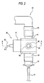
- Fig. 2 is an enlarged side view enlargedly showing the vicinity of a respiratory airway adaptor 20 of the respiratory waveform analyzer 10
- Fig. 3 is a sectional view of the A-A section of Fig. 2 as viewed in the direction of the arrows in Fig. 2 .
- the respiratory waveform analyzer 10 is an apparatus which measures a temporal change of the CO 2 concentration in the expiration of a subject such as a patient who must undergo respiratory management, thereby monitoring the respiratory condition of the subject.
- the analyzer includes the respiratory airway adaptor 20, a Y-shaped adaptor 30, an insertion portion 40, a sensor portion 50, and a measuring device 60.
- a respiratory airway 26 through which the respiratory gas of the subject is to pass is disposed in the respiratory airway adaptor 20.
- a connection port 21 which is connected to a connection port 31 of the Y-shaped adaptor 30, and a connection port 22 which is connected to a connection adaptor 42 of the insertion portion 40 are disposed on the both ends of the respiratory airway 26, respectively.
- a set of sensor attaching faces 24 which are parallel to each other are formed at intermediate positions of the respiratory airway 26 in the respiratory airway adaptor 20, respectively.
- the sensor attaching faces 24 are in contact with the inner face of a recess 54 of the sensor portion 50.
- a transmissive window 25 which is configured by fitting a transmissive member into a circular vacant hole is disposed in each of the sensor attaching faces 24.
- the transmissive windows 25 are disposed at positions which correspond to openings 56 in the inner face of the recess 54 when the sensor portion 50 is attached, respectively.
- the Y-shaped adaptor 30 has: the connection port 31 which is connected to the connection port 21 of the respiratory airway adaptor 20; an inspiratory air pipe 32 which is to be connected to an air supply source side of a ventilator; and an expiration air pipe 33 which is to be connected to an expiratory discharge valve side of the ventilator.
- the Y-shaped adaptor 30 is a member through which air that is supplied from, for example, the ventilator to the subject passes, and the expiration from the subject passes to the expiratory discharge valve side of the ventilator.
- the insertion portion 40 has a tube 41 which is to be inserted into the airway of the subject, and a connection adaptor 42 which mediates connection between one end of the tube 41 and the connection port 22 of the respiratory airway adaptor 20.
- the sensor portion 50 has: a sensor housing portion 51 which has a substantially U-like shape, and in which a light emitter 52 that emits infrared light, and a light receiver 53 that receives the infrared light from the light emitter 52, and that outputs a voltage the level of which corresponds to the intensity of the received light are disposed; and a connection cable 55 through which the sensor housing portion 51 is connected to the body unit 61 of the measuring device 60. As shown in Figs. 1 and 3 , the light emitter 52 and the light receiver 53 are opposed to each other across the recess 54 formed in the sensor housing portion 51.
- the circular openings 56 are disposed at the positions where the light emitter 52 and the light receiver 53 are disposed, in the inner face of the recess 54.
- the light emitter 52 is electrically connected through wirings 52a, 52b
- the light receiver 53 is electrically connected through wirings 53a, 53b to the body unit 61 of the measuring device 60.
- the light emitter 52 emits infrared light in accordance with the electric power supplied from the body unit 61.
- the light emitter 52 a device for emitting light of a wavelength at which the rate of absorption by CO 2 gas is higher as compared with the longer and shorter wavelength sides is used.
- the light receiver 53 outputs a voltage the level of which is substantially proportional to the CO 2 concentration.
- the light emitter 52 is a single light source emitting light having a large band and the light receiver 53 narrows the band by using a filter when receiving the light.
- the measuring device 60 has the body unit 61 which is connected to the sensor housing portion 51 of the sensor portion 50 through a connection cable 55, and a displaying portion 62 and operating portion 63 which are disposed in the front face of the body unit 61.
- the respiratory waveform analyzer 10 is used for measuring the concentration of carbon dioxide (CO 2 concentration) in the expiration or inspiration (hereinafter, both are generally referred as "respiration") of the subject.
- the respiration of the subject which passes through the respiratory airway 26 of the respiratory airway adaptor 20 is irradiated with the infrared light which is emitted from the light emitter 52 in accordance with the electric power supplied from the measuring device 60, and transmitted light is received by the light receiver 53. Then, the light receiver 53 outputs a voltage the level of which corresponds to the intensity of the received light, to the measuring device 60.
- the measuring device 60 Based on the voltage from the light receiver 53, the measuring device 60 detects the partial pressure of carbon dioxide in the pressure of the respiration which passes through the respiratory airway 26.
- the partial pressure of carbon dioxide has a value corresponding to the concentration of CO 2 contained in the respiration which passes through the respiratory airway 26. In the following description, therefore, the partial pressure of carbon dioxide detected by the measuring device 60 is referred to as the CO 2 concentration.
- the measuring device 60 generates a waveform based on a temporal change of the detected CO 2 concentration, and displays the waveform on the displaying portion 62.
- the waveform is referred to as the respiratory waveform.
- Various measurement conditions in the measurement, a change of the manner of displaying the respiratory waveform on the displaying portion 62, and the like can be set as predetermined ones by operating the operating portion 63 of the measuring device 60.
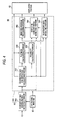
- Fig. 4 is a functional block diagram showing the configuration of the measuring device 60.
- the illustration of the configuration related to the power supply to the light emitter 52 is omitted (the same shall apply to the other functional block diagrams).
- the measuring device 60 has a respiratory gas concentration detecting portion 100 and a calculating processing portion 200, in the body unit 61.
- the calculating processing portion 200 includes a respiratory gas concentration calculating portion 210, a flatness calculating portion 220, a reliability calculating portion 230, a respiratory rate detecting portion 240, an effective concentration detecting portion 250, and a weighted average processing portion 260.
- the respiratory gas concentration detecting portion 100 When receiving an analog output signal which is supplied in, for example, a time continuous manner from the sensor portion 50, the respiratory gas concentration detecting portion 100 converts the analog signal to a digital respiratory gas signal which corresponds to the level of the analog signal, and supplies the digital signal to the respiratory gas concentration calculating portion 210 and the effective concentration detecting portion 250.
- the respiratory gas concentration detecting portion 100 is configured by an A/D converter and the like.
- the respiratory gas concentration detecting portion 100 and the respiratory gas concentration calculating portion 210 correspond to the respiratory gas concentration generating portion in the invention.
- the respiratory gas concentration calculating portion 210 receives the voltage (respiratory gas signal) of a level which corresponds to the CO 2 concentration supplied from the respiratory gas concentration detecting portion 100, and generates the respiratory waveform.
- the respiratory gas concentration calculating portion 210 supplies the generated respiratory waveform to the displaying portion 62, the flatness calculating portion 220, the reliability calculating portion 230, the respiratory rate detecting portion 240, and the effective concentration detecting portion 250.
- the flatness calculating portion 220 calculates the flatness indicative of the flat degree of the respiratory waveform supplied from the respiratory gas concentration calculating portion 210.
- the flatness calculating portion 220 calculates the difference between previous and current CO 2 concentrations at specific time intervals, and then calculates the flatness based on degree of the difference.
- the degree of the difference may be an absolute value of the difference and may be obtained by raising the difference to the power of the even number.
- the flatness calculating portion 220 calculates the flatness by using the following calculation expression (Exp. 1).
- the flatness calculating portion 220 sequentially outputs the calculated flatness in a time series manner to the reliability calculating portion 230.
- Y 0 1 / ⁇ ⁇ D ⁇ tCO ⁇ 2 2 + 1 Y [0]: current flatness in the respiratory waveform
- D ⁇ tCO2 difference between previous and current CO 2 concentrations at time interval ⁇ t
- the time interval ⁇ t may be, for example, 0. 05 seconds
- ⁇ (D ⁇ tCO2) 2 may be, for example, an accumulated value of the squares of the differences which are calculated during 0.1 seconds immediately before the calculation of the flatness.
- the flatness calculated by the flatness calculating portion 220 is a function of the accumulated value of the squares of the differences, and has the maximum value when the accumulated value is minimum.
- Fig. 5 shows an example of the respiratory waveform and the flatness of the respiratory waveform.
- the flatness is reduced in portions (the vicinities of 5 and 15 seconds in Fig. 5 ) where the temporal change of the CO 2 concentration is violent due to, for example, adhesion of water droplets to the transmissive windows 25 of the respiratory airway adaptor 20, and those (the vicinities of 9 and 20 seconds in Fig. 5 ) where the CO 2 concentration is varied due to spontaneous respiration of the subject or the like.
- the reliability calculating portion 230 calculates the reliability of the respiratory waveform on the basis of the degree of the flatness supplied from the flatness calculating portion 220, and the respiratory waveform supplied from the respiratory gas concentration calculating portion 210. Specifically, the reliability calculating portion 230 calculates, as the reliability, a value in which the flatness calculated by the flatness calculating portion 220 is multiplied with the value (the degree of the CO 2 concentration) of the respiratory waveform corresponding to the timing of calculating the flatness. Then, the reliability calculating portion 230 sequentially outputs the calculated reliability in a time series manner to the respiratory rate detecting portion 240, the effective concentration detecting portion 250, and the weighted average processing portion 260.
- Fig. 6 shows an example of the respiratory waveform and the reliability of the respiratory waveform.
- the reliability of the respiratory waveform shows a tendency to reduce irrespective of the degree of the CO 2 concentration. Namely, the reliability shows a reduction tendency when the respiratory waveform is largely varied in a short time period because, for example, water droplets adhere to the transmissive windows 25 of the respiratory airway adaptor 20, or the subject performs spontaneous respiration.
- the effective concentration detecting portion 250 detects the time period corresponding to one cycle from the respiratory waveform supplied from the respiratory gas concentration calculating portion 210.
- the effective concentration detecting portion 250 detects a portion of the respiratory waveform, extending from a timing when the CO 2 concentration exceeds a predetermined threshold (C th ) to that when the CO 2 concentration again falls below the threshold, as an expiratory waveform in one cycle of the respiratory waveform.
- C th a predetermined threshold
- the effective concentration detecting portion 250 detects eight expiratory waveforms (W 1 to W 8 ).
- the effective concentration detecting portion 250 detects time periods respectively corresponding to the expiratory waveforms, as concentration detecting time periods (T 1 to T 8 ) in the expiratory waveforms. As shown in Fig. 6 , for example, the effective concentration detecting portion 250 detects the concentration detecting concentration detecting time periods (T 1 to T 8 ) for the eight expiratory waveforms (W 1 to W 8 ), respectively.
- the effective concentration detecting portion 250 extracts reliabilities in the respective concentration detecting time periods, and detects timings when the value of the reliability is maximum. As shown in Fig. 6 , for example, the effective concentration detecting portion 250 extracts the reliabilities (R 1 to R 8 ) in the respective concentration detecting time periods (T 1 to T 8 ), and detects the timings (P 1 to P 8 ) when the value of the reliability is maximum in each of the concentration detecting time periods.
- the effective concentration detecting portion 250 detects the value (CO 2 concentration) of the expiratory waveform at the timing when the reliability is maximum in each of the concentration detecting time periods, as the effective concentration in the expiratory waveform. As shown in Fig. 6 , for example, the effective concentration detecting portion 250 detects the CO 2 concentrations at the timings (P 1 to P 8 ) which are detected in the respective concentration detecting time periods (T 1 to T 8 ), as the effective concentrations in the corresponding expiratory waveforms (W 1 to W 8 ), respectively.
- the effective concentration detecting portion 250 does not detect the CO 2 concentration at the timing as the effective concentration.
- the respiratory waveform analyzer 10 of the embodiment can correctly know noise components in the respiratory waveform on the basis of the reliability calculated by the reliability calculating portion 230. Even in the case where the respiratory waveform is largely varied due to, for example, adhesion of water droplets to the transmissive windows 25 of the respiratory airway adaptor 20, when the reliability is used, a peak of the varying portion is not detected as the effective concentration, and the effective CO 2 concentration in each cycle of the respiratory waveform can be detected with a higher accuracy.
- Fig. 7 shows a respiratory waveform, the reliability of the respiratory waveform, and the accumulated value of reliabilities during each of concentration detecting time periods.
- the respiratory waveform and reliability of the respiratory waveform which are shown in Fig. 7 are identical with those shown in Fig. 6 . Therefore, the expiratory waveforms (W 1 to W 8 ), concentration detecting time periods (T 1 to T 8 ), and the like which are denoted by the same reference numerals as those of Fig. 6 are identical with those shown in Fig. 6 , and hence their description is omitted,
- the effective concentration detecting portion 250 accumulates the reliabilities in the respective concentration detecting time periods, and compares the value of the accumulation with a predetermined lower-limit reliability. Then, the effective concentration detecting portion 250 detects the effective concentration, only in concentration detecting time periods when the accumulated value exceeds the lower-limit reliability.
- the effective concentration detecting portion 250 accumulates the reliabilities in each of the concentration detecting time periods (T 1 to T 8 ), to calculate accumulated values (S 1 to S 8 ) respectively corresponding to the concentration detecting time periods.
- the effective concentration detecting portion 250 calculates the accumulated values (S 1 to S 8 ) of the reliabilities in the respective concentration detecting time periods (T 1 to T 8 ), and compares the accumulated values with the lower-limit reliability.
- the effective concentration detecting portion 250 detects the effective concentration in only the concentration detecting time periods (T 1 , T 2 , T 4 , T 5 , T 7 , T 8 ) corresponding to, among the accumulated values, the accumulated values (S 1 , S 2 , S 4 , S 5 , S 7 , S 8 ) which are larger than the lower-limit reliability.
- the effective concentration detecting portion 250 supplies the detected effective concentrations (hereinafter, indicated by C 1 , C 2 , C 4 , C 5 , C 7 , C 8 ) to the weighted average processing portion 260 and the displaying portion 62.
- the displaying portion 62 displays the effective concentrations.
- the effective concentration detecting portion 250 does not detect the effective concentration with respect to an expiratory waveform which is generated by, for example, spontaneous respiration of the subject, and which has a low reliability, and therefore can detect the effective CO 2 concentration with respect to only normal expiration from the subject for the air supply from the ventilator.
- the respiratory rate detecting portion 240 detects the respiratory rate per unit time period, on the basis of the respiratory waveform supplied from the respiratory gas concentration calculating portion 210 and the reliability supplied from the reliability calculating portion 230. Similarly with the effective concentration detecting portion 250, specifically, the respiratory rate detecting portion 240 detects, for example, a portion of the respiratory waveform, extending from a timing when the CO 2 concentration exceeds a predetermined threshold to that when the CO 2 concentration again falls below the threshold, as an expiratory waveform in one cycle of the respiratory waveform.
- the respiratory rate detecting portion 240 calculates the accumulated values of the reliabilities supplied from the reliability calculating portion 230, and, similarly with the effective concentration detecting portion 250, compares the accumulated values with the lower-limit reliability. With respect to only expiratory waveforms corresponding to, among the accumulated values, accumulated values which exceed the lower-limit reliability, then, the respiratory rate detecting portion 240 detects the respiratory rate of the subject per unit time period, and supplies numerical data of the respiratory rate to the displaying portion 62. The displaying portion 62 displays the respiratory rate of the subject per unit time period.
- the respiratory rate is not counted with respect to an expiratory waveform which is generated by, for example, spontaneous respiration of the subject, and which has a low reliability. Therefore, the respiratory rate based on the respiratory motion of the subject with respect to the air supply from the ventilator can be detected more correctly.
- the weighted average processing portion 260 calculates a weighted average value in which the effective concentrations are weighted respectively in accordance with the degrees of accumulated values of the reliabilities corresponding to the effective concentrations, and then averaged.
- the weighted average processing portion 260 calculates a weighted average value on the basis of the following calculation expression (Exp. 2), from the effective concentrations (C 1 , C 2 , C 4 , C 5 , C 7 , C 8 ) which are detected from the expiratory waveforms W 1 , W 2 , W 4 , W 5 , N 7 , W 8 by the effective concentration detecting portion 250, and the accumulated values (S 1 , S 2 , S 4 , S 5 , S 7 , S 8 ) of the reliabilities respectively corresponding to the correct expiratory waveforms.
- the effective concentrations C 1 , C 2 , C 4 , C 5 , C 7 , C 8
- the weighted average processing portion 260 supplies the calculated weighted average value to the displaying portion 62.
- the displaying portion 62 displays the weighted average value.
- AV C ⁇ 1 ⁇ S ⁇ 1 + C ⁇ 2 ⁇ S ⁇ 2 + C ⁇ 4 ⁇ S ⁇ 4 + C ⁇ 5 ⁇ S ⁇ 5 + C ⁇ 7 ⁇ S ⁇ 7 + C ⁇ 8 ⁇ S ⁇ 8 / S ⁇ 1 + S ⁇ 2 + S ⁇ 4 + S ⁇ 5 + S ⁇ 7 + S ⁇ 8 AV : weighted average value
- the weighted average processing portion 260 may update the weighted average value in accordance with that the effective concentration detecting portion 250 newly detects the effective concentration on the basis of the respiratory waveform. For example, the weighted average processing portion 260 may update the weighted average value, at constant time intervals in accordance with the new effective concentration which is detected by the effective concentration detecting portion 250, and the degree of the accumulated value of reliabilities corresponding to the effective concentration.
- a weighted average value is calculated in which the effective concentrations detected from the respiratory waveform are weighted and averaged in accordance with accumulated values of the reliabilities of the respiratory waveform. Therefore, the detected effective concentrations are displayed as they are on the displaying portion 62, and also can be displayed as the average value in which the effective concentrations calculated from the expiratory waveform having low noise components are more reflected.
- Fig. 8 shows an example of a waveform of the voltage (V sig ) supplied from the respiratory gas concentration detecting portion 100, and a respiratory waveform which is generated on the basis of the waveform of the voltage.
- V sig the voltage supplied from the respiratory gas concentration detecting portion 100
- W 11 to W 13 are respiratory waveforms which are detected by the effective concentration detecting portion 250 on the basis of comparison with the predetermined threshold (C th ).
- T 11 to T 13 indicate concentration detecting time periods for the expiratory waveforms (W 11 to W 13 ), respectively.
- the respiratory waveform analyzer 10 when the intensity of the received light in the light receiver 53 of the sensor portion 50 is lowered by, for example, adhesion of water droplets to the transmissive windows 25 of the respiratory airway adaptor 20, also the value of the voltage supplied from the light receiver 53 is lowered in accordance with the lowering of the intensity.
- the respiratory waveform which is generated by the respiratory gas concentration calculating portion 210 is sometimes abruptly varied irrespective of the actual degree of the concentration of CO 2 contained in the respiration which passes through the respiratory airway 26.
- the effective concentration detecting portion 250 receives the voltage (V sig ) supplied from the respiratory gas concentration detecting portion 100, and compares the voltage with a preset lower-limit voltage. Then, the effective concentration detecting portion 250 removes time periods in which the value of the voltage (V sig ) is smaller than the lower-limit voltage (V th ), from the concentration detecting time periods for the respiratory waveform. In the respiratory waveform shown in Fig.
- the effective concentration detecting portion 250 detects the effective concentration in time periods that are obtained by removing time periods (T D1 to T D3 ) in which the value of the voltage (V sig ) is smaller than the lower-limit voltage (V th ), from the concentration detecting time periods (T 11 to T 13 ) for the expiratory waveforms (W 11 to W 13 ).
- the effective concentration is detected after noise components in the respiratory waveform are removed, and hence the effective concentration of CO 2 contained in the respiration of the subject can be detected more correctly.
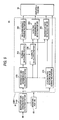
- Fig. 9 is a functional block diagram showing the configuration of a measuring device 65 in another example of the embodiment.
- the measuring device 65 components similar to those of the measuring device 60 which has been described with reference to Fig. 4 are denoted by the same reference numerals, and their description is omitted.
- the measuring device 65 has the respiratory gas concentration detecting portion 100 and a calculating processing portion 201, in the body unit 61.
- the calculating processing portion 201 includes a concentration detection value correcting portion 270 in addition to the components which are included by the calculating processing portion 200.
- the concentration detection value correcting portion 270 receives the voltage supplied from the respiratory gas concentration detecting portion 100, and corrects the respiratory waveform in accordance with the ratio of the voltage value to a predetermined reference voltage value. Specifically, the concentration detection value correcting portion 270 calculates a correction value in which the CO 2 concentration corresponding to the voltage value in the respiratory waveform is corrected on the basis of, for example, the following calculation expression (Exp. 3), and outputs a time series of the correction value as a corrected respiratory waveform to the displaying portion 62 and the respiratory rate detecting portion 240. The displaying portion 62 displays the corrected respiratory waveform.
- F_CO ⁇ 2 0 a ⁇ Vsig / Vsig ⁇ 0 b ⁇ Cp + 1 - a ⁇ Vsig / Vsig ⁇ 0 b ⁇ F_CO ⁇ 2 1
- Cp current CO 2 concentration
- Vsig current voltage value
- Vsig 0 reference voltage value
- b weighting adjustment factor
- the reference voltage value (Vsig0) is a voltage value which is supplied from the respiratory gas concentration detecting portion 100 when the measurement is performed by the respiratory waveform analyzer 10 in a state where no gas exists in the respiratory airway 26 of the respiratory airway adaptor 20.
- the weighting adjustment factors (a, b) are factors for adjusting the correction value to a value in which the ratio (Vsig/Vsig0) of a change of the current voltage value (the voltage value to be corrected) to the reference voltage value is more reflected to the current CO 2 concentration (Cp), or that in which the ratio is more reflected to the CO 2 concentration (F_CO2[1]) at the previous timing.
- a is a value in the range of 0 to 1
- b is a value which is equal to or larger than 0.
- Fig. 10 shows an example of the waveform of the voltage (V sig ) supplied from the respiratory gas concentration detecting portion 100, the respiratory waveform which is generated on the basis of the waveform of the voltage, and a corrected respiratory waveform, in the measuring device 65.
- the waveform indicated by "CO 2 CONCENTRATION” in Fig. 10 is the respiratory waveform which is generated by the respiratory gas concentration calculating portion 210 on the basis of the voltage (V sig ) supplied from the respiratory gas concentration detecting portion 100, and the waveform indicated by "CORRECTED CO 2 CONCENTRATION” in Fig. 10 is the respiratory waveform which is obtained by correcting the waveform indicated by "CO 2 CONCENTRATION", in accordance with the calculation expression of Exp. 3 above by the concentration detection value correcting portion 270.
- both the weighting adjustment factors (a, b) in Exp. 3 above are set to 1.
- the concentration detection value correcting portion 270 calculates the correction value (F_CO2[0]) in which, as the ratio of the voltage (V sig ) supplied from the respiratory gas concentration detecting portion 100 to the reference voltage value (V sig0 ) is smaller, the CO 2 concentration (Cp) generated by the respiratory gas concentration calculating portion 210 on the basis of the voltage (V sig ) is made smaller in accordance with the ratio.
- the concentration detection value correcting portion 270 can generate a respiratory waveform in which an abrupt change of the CO 2 concentration (Cp) due to the measurement error cause is mitigated.
- the respiratory rate detecting portion 240 can detect more correctly the respiratory rate of the subject per unit time period, and the displaying portion 62 can display a respiratory waveform which is less affected by the measurement error cause, and which is more similar to the CO 2 concentration of the respiration of the subject.
- Water which is generated in the respiratory circuit during the use of the respiratory waveform analyzer 10 of the embodiment constitutes not only the error cause of the measurement of the CO 2 concentration as described above, but also may constitute a cause of pneumonia when the patient erroneously sucks the water. Therefore, the generation of water must be detected more correctly.
- the respiratory waveform analyzer 10 which can solve such a problem will be exemplarily described.
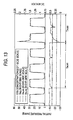
- Fig. 11 is a functional block diagram showing the configuration of a measuring device 66 in a further example of the embodiment.
- Figs. 12 to 15 show examples of a waveform of the voltage (V sig ) supplied from the respiratory gas concentration detecting portion 100, and a respiratory waveform which is generated on the basis of the waveform of the voltage, in the measuring device 66.
- the measuring device 66 shown in Fig. 11 components similar to those of the measuring device 60 which has been described with reference to Fig. 4 or those of the measuring device 65 which has been described with reference to Fig. 9 are denoted by the same reference numerals, and their description is omitted.
- the waveforms indicated by "CO 2 CONCENTRATION" in Figs. 12 to 15 are the respiratory waveform which is generated by the respiratory gas concentration calculating portion 210 on the basis of the voltage (V sig ) supplied from the respiratory gas concentration detecting portion 100.
- the measuring device 66 has the respiratory gas concentration detecting portion 100 and a calculating processing portion 202, in the body unit 61.
- the calculating processing portion 202 includes a reserved water detecting portion 280 in addition to the components which are included by the calculating processing portion 200.
- the reserved water detecting portion 280 receives the voltage (V sig ) supplied from the respiratory gas concentration detecting portion 100, and compares the value of the voltage (V sig ) with a preset attention arousing voltage (V ALM1 ).
- the attention arousing voltage (V ALM1 ) is set to a level at which the voltage (V sig ) is higher than the attention arousing voltage (V ALM1 ) in the case where, in the use of the respiratory waveform analyzer 10, the measurement is performed without causing water to adhere to the transmissive windows 25 of the respiratory airway adaptor 20.
- the intensity of light received by the light receiver 53 of the sensor portion 50 is lowered.
- the voltage (V sig ) is lowered in accordance with the the lowering of the intensity of the light received by the light receiver 53, to be lower than the attention arousing voltage (V ALM1 ) as shown in Fig. 12
- the reserved water detecting portion 280 supplies an attention arousing signal indicative of a possibility that water is reserved in the respiratory airway adaptor 20, to the displaying portion 62.
- the displaying portion 62 Upon receiving the attention arousing signal, the displaying portion 62 displays for a constant time period (T ALM1 ) an attention arousing message indicating that water may be possibly reserved in the respiratory airway adaptor 20, based on the attention arousing signal.
- T ALM1 a constant time period
- the reserved water detecting portion 280 compares the value of the voltage (V sig ) with a preset alarm voltage (V ALM2 ).
- the alarm voltage (V ALM2 ) is set to a level at which the voltage (V sig ) is lower than the alarm voltage (V ALM2 ) in the case where, in the use of the respiratory waveform analyzer 10, the measurement is performed in a state where water adheres to a substantially whole face of the transmissive windows 25 of the respiratory airway adaptor 20.
- the reserved water detecting portion 280 supplies an alarm signal indicating that water is reserved in the respiratory airway adaptor 20, to the displaying portion 62.
- the displaying portion 62 displays for a constant time period (T ALM2 ) an alarm message indicating, for example, that water is reserved in the respiratory airway adaptor 20, based on the alarm signal.
- the reserved water detecting portion 280 may accumulate the number at which the value of the voltage (V sig ) is smaller than the preset attention arousing voltage (V ALM1 ) as shown in Fig. 14 , for each respiratory waveform, and, at a timing when the number of smaller values reaches a preset number (in Fig. 14 , three), supply the attention arousing signal to the displaying portion 62. Moreover, the reserved water detecting portion 280 may count the number at which the value of the voltage (V sig ) is smaller than the attention arousing voltage (V ALM1 ), and, at a timing when the counted number reaches a preset number (in Fig. 14 , eight) which is a number larger than the above-mentioned number, supply the alarm signal to the displaying portion 62.
- the reserved water detecting portion 280 may accumulate the time period during which the value of the voltage (V sig ) is smaller than the preset attention arousing voltage (V ALM1 ) as shown in Fig. 15 , and, at a timing when the accumulated time period reaches a preset time period, supply the attention arousing signal to the displaying portion 62. Moreover, the reserved water detecting portion 280 may accumulate the time period during which the value of the voltage (V sig ) is smaller than the preset alarm voltage (V ALM2 ) as shown in Fig. 15 , and, at a timing when the accumulated time period reaches a preset time period, supply the alarm signal to the displaying portion 62.
- the respiratory waveform analyzer 10 of the embodiment further includes the reserved water detecting portion 280, and hence can detect that water is reserved in the respiratory airway adaptor 20, to perform an attention arousal and an alarm to the user of the apparatus.
- the attention arousal and alarm related to reserving of water in the respiratory airway adaptor 20 are performed by means of a message display on the displaying portion 62.
- the attention arousal and the alarm may be performed by means of, for example, a buzzer or an audio assist.
- the light emitter 52 emits light (signal light) of a band in which the rate of absorption by CO 2 gas is high, and the light receiver 53 receives the light which has undergone absorption in accordance with the concentration of CO 2 contained in the respiration.
- the light emitter 52 emits also light (referential light) of a band in which the rate of absorption by CO 2 gas is low, in addition to the signal light.
- the respiratory waveform analyzer 10 which will be described below has a configuration similar to that of the respiratory waveform analyzer 10 of the above-described embodiment example.
- the light emitter 52 alternately emits the signal light and the referential light.
- the respiratory gas concentration detecting portion 100 outputs voltages of levels which correspond to the receiving intensities of the signal light and the referential light, respectively.
- the respiratory gas concentration detecting portion 100 outputs the voltage (V sig ) of a level which corresponds to the receiving intensity of the signal light, and also a voltage (V rof ) of a level which corresponds to the receiving intensity of the referential light. Since the referential light is not substantially absorbed by CO 2 as compared with the signal light, the value of the voltage (V ref ) is changed by increasing and decreasing of the concentration of CO 2 contained in the respiration, in a less degree as compared with the voltage (V sig ).
- a plurality of light sources for emitting light may be provided respectively as the light emitter 52.
- the configuration may be used in which a single light source for emitting light having a large band is provided as the light emitter 52, the light from the single light source is divided at the light receiver 53 and the signal light and the referential light are generated by using filters, which have different characteristics, for filtering the divided light.
- the absorption coefficient (E) of the water reserved in the respiratory airway adaptor 20, and the concentration (C) of the water can be regarded as constants, and hence above expression (Exp. 5) is an expression showing the relationship between the quantity of water reserved in the respiratory airway adaptor 20 and the degree of attenuation of the referential light caused by the water (the attenuance due to water).
- V ref0 the voltage which is output by the respiratory gas concentration detecting portion 100 on the basis of the receiving intensity of the standard referential light
- ref/ref0 can be approximated by V ref /V ref0 .
- the reserved water detecting portion 280 stores expression (Exp. 5) above, and the components of expression (Exp. 5) above, i.e., the absorption coefficient (E), the concentration (C), and the voltage (V ref0 ) corresponding to the receiving intensity of the standard referential light are preset.
- the voltage (V ref0 ) corresponding to the receiving intensity of the standard referential light may be obtained by actual measurement, or alternatively may be obtained, for example, in the following manner on the basis of V ref and the ratio (V sig /V ref ) of V sig and V ref .
- Fig. 16 shows relationships between V ref and V sig /V ref due to a change of the CO 2 concentration of the respiratory.
- Each of the plots shown in Fig. 16 shows the relationship between V ref and V sig /V ref at the CO 2 concentration indicated in the vicinity of the plot.
- the straight line shown in Fig. 16 shows a linear approximation of the plots.
- the value of the voltage (V ref0 ) corresponding to the receiving intensity of the referential light (standard referential light) in a state where no water is reserved in the respiratory airway adaptor 20 can be approximately obtained by the value of V ref in the case where V sig /V ref is 1.0 on the straight line obtained by the linear approximation of the plots (the value of V ref at the plot indicated by " ⁇ " in Fig. 16 ).
- Fig. 17 shows an example of waveforms of V sig , V ref , and the CO 2 concentration which is generated on the basis of V sig , in the state where water is not reserved in the optical paths of the signal light and the referential light inside the respiratory airway adaptor 20, and Fig. 18 shows relationships between the waveforms of V sig and V ref , and the attenuance due to water which is reserved in the respiratory airway adaptor 20, in the state.
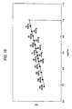
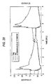
- Fig. 19 shows an example of waveforms of V sig , V ref , and the CO 2 concentration which is generated on the basis of V sig , in the state where water is reserved in the optical paths of the signal light and the referential light inside the respiratory airway adaptor 20, and Fig. 20 shows relationships between the waveforms of V sig and V ref , and the attenuance due to water which is reserved in the respiratory airway adaptor 20, in the state.
- the reserved water detecting portion 280 calculates the attenuance (ECD in Exp. 5) showing such a tendency, and, based on the value of the tendency, can detect the quantity of water reserved in the respiratory airway adaptor 20.
- the object for the detection is described as the water.
- the respiratory waveform analyzer 10 according to an aspect of the above embodiment can detect a material, for example a liquid, other than the water.
- the respiratory waveform analyzer 10 is an apparatus for measuring the CO 2 concentration in the respiration of the subject, for example, the invention is not restricted to an apparatus for measuring a specific component in the respiration of the subject.
- an apparatus for measuring one or more components in the expiration or inspiration of the subject belongs to the technical scope of the invention.
- the reliability of the respiratory waveform is referred, and therefore it is possible to correctly know noise components in the respiratory waveform.
- the use of the reliability causes a peak of noise components contained in the waveform corresponding to each respiration cycle, not to be falsely detected as the effective concentration.
- the averaging is performed after the effective concentrations are weighted in accordance with the degree of the accumulated values of the reliabilities in the waveforms. Therefore, the effect of the noise components contained in the waveforms against the calculated average value (weighted average value) can be reduced.
- the effective concentration detecting portion detects the effective concentration during the concentration detecting time period. Therefore, the following effect is attained. Even in the case where, when the concentration of the component in the respiratory gas is measured by using the IR spectroscopy, water droplets or the like are attached to a light irradiation portion or detection portion for the expiration, and the level of the output signal from the detection portion is lowered, the detection is not affected by the level lowering of the output signal due to such an error cause, and hence it is possible to detect more correctly the effective concentration.
- the apparatus includes the concentration detection value correcting portion which corrects the respiratory waveform signal corresponding to the respiratory gas signal, in accordance with the ratio of the respiratory gas signal to the predetermined reference value. Even when a measurement involving the error cause is performed, therefore, an effect caused by the level lowering of the output signal can be reduced. Even in the case where the concentration signal is largely varied in one respiration cycle by the error cause, consequently, it is possible to prevent determination that a plurality of respirations are conducted, from being performed based on the waveform (the respiratory waveform signal) due to the concentration signal. Further, since the apparatus includes the reserved water detecting portion, it is possible to detect the water in the respiratory airway adaptor and to perform an attention arousal and an alarm to the user of the apparatus.
Landscapes
- Health & Medical Sciences (AREA)
- Life Sciences & Earth Sciences (AREA)
- Physics & Mathematics (AREA)
- General Health & Medical Sciences (AREA)
- Engineering & Computer Science (AREA)
- Pathology (AREA)
- Physiology (AREA)
- Veterinary Medicine (AREA)
- Public Health (AREA)
- Animal Behavior & Ethology (AREA)
- Surgery (AREA)
- Molecular Biology (AREA)
- Medical Informatics (AREA)
- Heart & Thoracic Surgery (AREA)
- Spectroscopy & Molecular Physics (AREA)
- Biomedical Technology (AREA)
- Biophysics (AREA)
- Immunology (AREA)
- Obesity (AREA)
- Computer Vision & Pattern Recognition (AREA)
- Artificial Intelligence (AREA)
- Chemical & Material Sciences (AREA)
- Analytical Chemistry (AREA)
- Biochemistry (AREA)
- General Physics & Mathematics (AREA)
- Psychiatry (AREA)
- Emergency Medicine (AREA)
- Signal Processing (AREA)
- Pulmonology (AREA)
- Measurement Of The Respiration, Hearing Ability, Form, And Blood Characteristics Of Living Organisms (AREA)
- Investigating Or Analysing Materials By Optical Means (AREA)
Priority Applications (1)
| Application Number | Priority Date | Filing Date | Title |
|---|---|---|---|
| EP13187035.4A EP2682054A1 (de) | 2009-03-30 | 2010-03-30 | Atemwellenformanalysiergerät |
Applications Claiming Priority (1)
| Application Number | Priority Date | Filing Date | Title |
|---|---|---|---|
| JP2009082039A JP5351583B2 (ja) | 2009-03-30 | 2009-03-30 | 呼吸波形解析装置 |
Related Child Applications (1)
| Application Number | Title | Priority Date | Filing Date |
|---|---|---|---|
| EP13187035.4A Division-Into EP2682054A1 (de) | 2009-03-30 | 2010-03-30 | Atemwellenformanalysiergerät |
Publications (3)
| Publication Number | Publication Date |
|---|---|
| EP2236079A2 true EP2236079A2 (de) | 2010-10-06 |
| EP2236079A3 EP2236079A3 (de) | 2013-04-03 |
| EP2236079B1 EP2236079B1 (de) | 2018-02-21 |
Family
ID=42335012
Family Applications (2)
| Application Number | Title | Priority Date | Filing Date |
|---|---|---|---|
| EP10158368.0A Active EP2236079B1 (de) | 2009-03-30 | 2010-03-30 | Atemwellenformanalysiergerät |
| EP13187035.4A Withdrawn EP2682054A1 (de) | 2009-03-30 | 2010-03-30 | Atemwellenformanalysiergerät |
Family Applications After (1)
| Application Number | Title | Priority Date | Filing Date |
|---|---|---|---|
| EP13187035.4A Withdrawn EP2682054A1 (de) | 2009-03-30 | 2010-03-30 | Atemwellenformanalysiergerät |
Country Status (3)
| Country | Link |
|---|---|
| US (2) | US9955899B2 (de) |
| EP (2) | EP2236079B1 (de) |
| JP (1) | JP5351583B2 (de) |
Families Citing this family (25)
| Publication number | Priority date | Publication date | Assignee | Title |
|---|---|---|---|---|
| FR2941530B1 (fr) * | 2009-01-28 | 2011-03-18 | S Seres Environnement Sa | Appareil ethylometre portable |
| JP5351583B2 (ja) | 2009-03-30 | 2013-11-27 | 日本光電工業株式会社 | 呼吸波形解析装置 |
| EP2651294B1 (de) | 2010-12-17 | 2016-03-16 | Koninklijke Philips N.V. | System und verfahren zur identifizierung von atemzügen aussschliesslich auf der basis von kapnografischen daten |
| US8783250B2 (en) | 2011-02-27 | 2014-07-22 | Covidien Lp | Methods and systems for transitory ventilation support |
| BR112014015145B1 (pt) * | 2011-12-21 | 2022-08-16 | Capnia, Inc. | Aparelho para analisar uma concentração de gás em uma respiração de um paciente e método para determinar uma concentração de um gás em uma respiração de um paciente |
| US9993604B2 (en) | 2012-04-27 | 2018-06-12 | Covidien Lp | Methods and systems for an optimized proportional assist ventilation |
| US9375542B2 (en) | 2012-11-08 | 2016-06-28 | Covidien Lp | Systems and methods for monitoring, managing, and/or preventing fatigue during ventilation |
| JP5352000B2 (ja) * | 2012-12-14 | 2013-11-27 | 日本光電工業株式会社 | 呼吸波形解析装置 |
| US10499819B2 (en) | 2013-01-08 | 2019-12-10 | Capnia, Inc. | Breath selection for analysis |
| BR112015019326A2 (pt) | 2013-02-12 | 2017-07-18 | Capnia Inc | dispositivo de registro de amostragem e armazenamento para análise de gás respiratório |
| US9358355B2 (en) | 2013-03-11 | 2016-06-07 | Covidien Lp | Methods and systems for managing a patient move |
| WO2015031850A1 (en) | 2013-08-30 | 2015-03-05 | Capnia, Inc. | Neonatal carbon dioxide measurement system |
| CN103712942A (zh) * | 2013-12-16 | 2014-04-09 | 天津大学 | 主流式人呼吸二氧化碳浓度实时监测方法 |
| US20180228399A1 (en) * | 2015-08-11 | 2018-08-16 | Koninklijke Philips N.V. | Capnography with decision support system architecture |
| US10791962B2 (en) * | 2017-01-26 | 2020-10-06 | Hamilton Sundstrand Corporation | Insulating a protective cover for a seal to sensor associated with a spacesuit |
| US11833296B2 (en) * | 2017-06-27 | 2023-12-05 | Nihon Kohden Corporation | Gas monitoring apparatus and system for artificial ventilation |
| WO2019099185A1 (en) | 2017-11-14 | 2019-05-23 | Covidien Lp | Methods and systems for drive pressure spontaneous ventilation |
| KR102076396B1 (ko) * | 2017-11-22 | 2020-02-11 | 송성호 | 이산화탄소 분압 측정 데이터를 보정하는 방법 및 장치 |
| US11517691B2 (en) | 2018-09-07 | 2022-12-06 | Covidien Lp | Methods and systems for high pressure controlled ventilation |
| KR102234616B1 (ko) * | 2019-03-26 | 2021-04-02 | 사회복지법인 삼성생명공익재단 | 백 밸브 마스크의 제어를 위한 피드백 장치 및 시스템 |
| CN110189822A (zh) * | 2019-05-23 | 2019-08-30 | 广州博而济信息科技有限公司 | 一种基于机械通气参数及波形进行智能分析的方法 |
| TWI771822B (zh) * | 2020-12-11 | 2022-07-21 | 康定股份有限公司 | 氣體濃度測量系統及其氣道轉接器 |
| KR102663808B1 (ko) * | 2021-12-14 | 2024-05-03 | (주)타이보메드 | 디지털 흡배기 호흡 모니터링 장치 및 이를 구비하는 수동식 인공호흡기 |
| CN114659475A (zh) * | 2022-04-07 | 2022-06-24 | 四川陆通检测科技有限公司 | 一种具有修正功能的锚杆长度测量系统及方法 |
| JPWO2024106544A1 (de) * | 2022-11-17 | 2024-05-23 |
Citations (1)
| Publication number | Priority date | Publication date | Assignee | Title |
|---|---|---|---|---|
| JP2003532442A (ja) | 1999-06-08 | 2003-11-05 | オリディオン メディカル リミティド | 呼吸分析用波形インタプリタ |
Family Cites Families (17)
| Publication number | Priority date | Publication date | Assignee | Title |
|---|---|---|---|---|
| CH629905A5 (de) * | 1978-07-17 | 1982-05-14 | Cerberus Ag | Gas- und/oder brandmeldeanlage. |
| US4570639A (en) * | 1982-12-30 | 1986-02-18 | Memorial Hospital For Cancer And Allied Diseases | Discontinuity detector |
| US4651746A (en) * | 1984-05-08 | 1987-03-24 | Wall William H | Oral airway and endotrachial monitor |
| JPS61100231A (ja) * | 1984-10-23 | 1986-05-19 | 株式会社東芝 | 呼吸監視装置 |
| US4648396A (en) * | 1985-05-03 | 1987-03-10 | Brigham And Women's Hospital | Respiration detector |
| US5140981A (en) * | 1986-11-24 | 1992-08-25 | Picker International, Inc. | End-tidal gas detection |
| US5003985A (en) * | 1987-12-18 | 1991-04-02 | Nippon Colin Co., Ltd. | End tidal respiratory monitor |
| FI921924A7 (fi) * | 1991-05-08 | 1992-11-09 | Nellcor Inc | Portabel koldioxidmonitor |
| US5386833A (en) * | 1993-12-23 | 1995-02-07 | Biochem International, Inc. | Method for calibrating a carbon dioxide monitor |
| JP3273299B2 (ja) * | 1995-02-24 | 2002-04-08 | 日本光電工業株式会社 | 炭酸ガス濃度測定装置 |
| DE69629510T2 (de) | 1995-02-24 | 2004-04-08 | Nihon Kohden Corp. | Kapnometer |
| US5965887A (en) | 1997-08-12 | 1999-10-12 | Datex-Ohmeda, Inc. | Method and apparatus for monitoring maintenance of calibration condition in respiratory gas spectrometer |
| DE60209784T2 (de) * | 2001-12-06 | 2006-11-30 | Cardinal Health 303, Inc., San Diego | Infusionsvorrichtung mit co2 überwachung |
| US7967759B2 (en) * | 2006-01-19 | 2011-06-28 | Boston Scientific Scimed, Inc. | Endoscopic system with integrated patient respiratory status indicator |
| GB2441781B (en) * | 2006-09-13 | 2010-05-19 | Autoliv Dev | Breath analyser |
| US20080119753A1 (en) * | 2006-11-16 | 2008-05-22 | Cardiopulmonary Technologies, Inc. | Premature infant side-stream respiratory gas monitoring sensor |
| JP5351583B2 (ja) | 2009-03-30 | 2013-11-27 | 日本光電工業株式会社 | 呼吸波形解析装置 |
-
2009
- 2009-03-30 JP JP2009082039A patent/JP5351583B2/ja active Active
-
2010
- 2010-03-30 EP EP10158368.0A patent/EP2236079B1/de active Active
- 2010-03-30 EP EP13187035.4A patent/EP2682054A1/de not_active Withdrawn
- 2010-03-30 US US12/749,607 patent/US9955899B2/en active Active
-
2012
- 2012-07-13 US US13/549,165 patent/US9655543B2/en active Active
Patent Citations (1)
| Publication number | Priority date | Publication date | Assignee | Title |
|---|---|---|---|---|
| JP2003532442A (ja) | 1999-06-08 | 2003-11-05 | オリディオン メディカル リミティド | 呼吸分析用波形インタプリタ |
Also Published As
| Publication number | Publication date |
|---|---|
| EP2236079B1 (de) | 2018-02-21 |
| US9955899B2 (en) | 2018-05-01 |
| EP2682054A1 (de) | 2014-01-08 |
| JP2010233611A (ja) | 2010-10-21 |
| US20100249631A1 (en) | 2010-09-30 |
| US20120283591A1 (en) | 2012-11-08 |
| EP2236079A3 (de) | 2013-04-03 |
| US9655543B2 (en) | 2017-05-23 |
| JP5351583B2 (ja) | 2013-11-27 |
Similar Documents
| Publication | Publication Date | Title |
|---|---|---|
| EP2236079B1 (de) | Atemwellenformanalysiergerät | |
| US10314515B2 (en) | Capnography device and method | |
| EP0512535B1 (de) | Tragbares Kohlendioxidüberwachungsgerät | |
| EP2097721B1 (de) | System und verfahren zur signalqualitätsbestimmung und signalkorrektur | |
| JP5382724B2 (ja) | 対話型アルコール検出 | |
| US20150230731A1 (en) | Exhaled breath sampling with delivery of gas | |
| US20100185112A1 (en) | Device for analysing an inflammatory status of a respiratory system | |
| US10052025B2 (en) | Sensor, gas analyzer and method for measuring concentration of at least one respiratory gas component | |
| US5386833A (en) | Method for calibrating a carbon dioxide monitor | |
| CN102608060B (zh) | 一种气体浓度测量方法及设备 | |
| US11448640B2 (en) | Respiratory gas sensor system with color detection | |
| JP2014509235A (ja) | リアルタイム気道チェック状態インジケータ | |
| EP2914321A1 (de) | Beatmungsvorrichtung und verfahren darin | |
| EP3334339B1 (de) | Kapnografie mit entscheidungsunterstützungssystemarchitektur | |
| US20110209703A1 (en) | Artificial ventilation apparatus | |
| EP3334341B1 (de) | Zubehörsystem für automatische probenahme | |
| JP5352000B2 (ja) | 呼吸波形解析装置 | |
| CN110522451B (zh) | 多组分气体中co弥散量的测量方法和系统 | |
| EP4371481A1 (de) | Verfahren und vorrichtung zur bestimmung der co2-konzentration in der arterien | |
| JP3273299B2 (ja) | 炭酸ガス濃度測定装置 | |
| CN211355472U (zh) | 一种带方向检测和防摔功能的主流气体测量装置 | |
| RU2790925C2 (ru) | Обнаружение принадлежности в капнографических модулях | |
| Ting et al. | Development of Smart Mask System Integrated with Alert Detection and Vital-sign Measurement | |
| CN103162735B (zh) | 一种气体监测装置、方法及医疗设备 | |
| Shakya et al. | Measurement of the frequency response of clinical gas analysers |
Legal Events
| Date | Code | Title | Description |
|---|---|---|---|
| PUAI | Public reference made under article 153(3) epc to a published international application that has entered the european phase |
Free format text: ORIGINAL CODE: 0009012 |
|
| AK | Designated contracting states |
Kind code of ref document: A2 Designated state(s): AT BE BG CH CY CZ DE DK EE ES FI FR GB GR HR HU IE IS IT LI LT LU LV MC MK MT NL NO PL PT RO SE SI SK SM TR |
|
| AX | Request for extension of the european patent |
Extension state: AL BA ME RS |
|
| RIC1 | Information provided on ipc code assigned before grant |
Ipc: A61B 5/083 20060101AFI20121114BHEP |
|
| PUAL | Search report despatched |
Free format text: ORIGINAL CODE: 0009013 |
|
| AK | Designated contracting states |
Kind code of ref document: A3 Designated state(s): AT BE BG CH CY CZ DE DK EE ES FI FR GB GR HR HU IE IS IT LI LT LU LV MC MK MT NL NO PL PT RO SE SI SK SM TR |
|
| AX | Request for extension of the european patent |
Extension state: AL BA ME RS |
|
| RIC1 | Information provided on ipc code assigned before grant |
Ipc: A61B 5/083 20060101AFI20130222BHEP |
|
| 17P | Request for examination filed |
Effective date: 20131002 |
|
| RBV | Designated contracting states (corrected) |
Designated state(s): AT BE BG CH CY CZ DE DK EE ES FI FR GB GR HR HU IE IS IT LI LT LU LV MC MK MT NL NO PL PT RO SE SI SK SM TR |
|
| 17Q | First examination report despatched |
Effective date: 20131129 |
|
| GRAP | Despatch of communication of intention to grant a patent |
Free format text: ORIGINAL CODE: EPIDOSNIGR1 |
|
| INTG | Intention to grant announced |
Effective date: 20170921 |
|
| GRAS | Grant fee paid |
Free format text: ORIGINAL CODE: EPIDOSNIGR3 |
|
| GRAA | (expected) grant |
Free format text: ORIGINAL CODE: 0009210 |
|
| AK | Designated contracting states |
Kind code of ref document: B1 Designated state(s): AT BE BG CH CY CZ DE DK EE ES FI FR GB GR HR HU IE IS IT LI LT LU LV MC MK MT NL NO PL PT RO SE SI SK SM TR |
|
| REG | Reference to a national code |
Ref country code: GB Ref legal event code: FG4D |
|
| REG | Reference to a national code |
Ref country code: CH Ref legal event code: EP |
|
| REG | Reference to a national code |
Ref country code: AT Ref legal event code: REF Ref document number: 970807 Country of ref document: AT Kind code of ref document: T Effective date: 20180315 |
|
| REG | Reference to a national code |
Ref country code: IE Ref legal event code: FG4D |
|
| REG | Reference to a national code |
Ref country code: DE Ref legal event code: R096 Ref document number: 602010048568 Country of ref document: DE |
|
| REG | Reference to a national code |
Ref country code: NL Ref legal event code: MP Effective date: 20180221 |
|
| REG | Reference to a national code |
Ref country code: LT Ref legal event code: MG4D |
|
| REG | Reference to a national code |
Ref country code: AT Ref legal event code: MK05 Ref document number: 970807 Country of ref document: AT Kind code of ref document: T Effective date: 20180221 |
|
| PG25 | Lapsed in a contracting state [announced via postgrant information from national office to epo] |
Ref country code: ES Free format text: LAPSE BECAUSE OF FAILURE TO SUBMIT A TRANSLATION OF THE DESCRIPTION OR TO PAY THE FEE WITHIN THE PRESCRIBED TIME-LIMIT Effective date: 20180221 Ref country code: CY Free format text: LAPSE BECAUSE OF FAILURE TO SUBMIT A TRANSLATION OF THE DESCRIPTION OR TO PAY THE FEE WITHIN THE PRESCRIBED TIME-LIMIT Effective date: 20180221 Ref country code: LT Free format text: LAPSE BECAUSE OF FAILURE TO SUBMIT A TRANSLATION OF THE DESCRIPTION OR TO PAY THE FEE WITHIN THE PRESCRIBED TIME-LIMIT Effective date: 20180221 Ref country code: NL Free format text: LAPSE BECAUSE OF FAILURE TO SUBMIT A TRANSLATION OF THE DESCRIPTION OR TO PAY THE FEE WITHIN THE PRESCRIBED TIME-LIMIT Effective date: 20180221 Ref country code: FI Free format text: LAPSE BECAUSE OF FAILURE TO SUBMIT A TRANSLATION OF THE DESCRIPTION OR TO PAY THE FEE WITHIN THE PRESCRIBED TIME-LIMIT Effective date: 20180221 Ref country code: NO Free format text: LAPSE BECAUSE OF FAILURE TO SUBMIT A TRANSLATION OF THE DESCRIPTION OR TO PAY THE FEE WITHIN THE PRESCRIBED TIME-LIMIT Effective date: 20180521 Ref country code: HR Free format text: LAPSE BECAUSE OF FAILURE TO SUBMIT A TRANSLATION OF THE DESCRIPTION OR TO PAY THE FEE WITHIN THE PRESCRIBED TIME-LIMIT Effective date: 20180221 |
|
| PG25 | Lapsed in a contracting state [announced via postgrant information from national office to epo] |
Ref country code: AT Free format text: LAPSE BECAUSE OF FAILURE TO SUBMIT A TRANSLATION OF THE DESCRIPTION OR TO PAY THE FEE WITHIN THE PRESCRIBED TIME-LIMIT Effective date: 20180221 Ref country code: GR Free format text: LAPSE BECAUSE OF FAILURE TO SUBMIT A TRANSLATION OF THE DESCRIPTION OR TO PAY THE FEE WITHIN THE PRESCRIBED TIME-LIMIT Effective date: 20180522 Ref country code: BG Free format text: LAPSE BECAUSE OF FAILURE TO SUBMIT A TRANSLATION OF THE DESCRIPTION OR TO PAY THE FEE WITHIN THE PRESCRIBED TIME-LIMIT Effective date: 20180521 Ref country code: LV Free format text: LAPSE BECAUSE OF FAILURE TO SUBMIT A TRANSLATION OF THE DESCRIPTION OR TO PAY THE FEE WITHIN THE PRESCRIBED TIME-LIMIT Effective date: 20180221 Ref country code: SE Free format text: LAPSE BECAUSE OF FAILURE TO SUBMIT A TRANSLATION OF THE DESCRIPTION OR TO PAY THE FEE WITHIN THE PRESCRIBED TIME-LIMIT Effective date: 20180221 |
|
| PG25 | Lapsed in a contracting state [announced via postgrant information from national office to epo] |
Ref country code: EE Free format text: LAPSE BECAUSE OF FAILURE TO SUBMIT A TRANSLATION OF THE DESCRIPTION OR TO PAY THE FEE WITHIN THE PRESCRIBED TIME-LIMIT Effective date: 20180221 Ref country code: IT Free format text: LAPSE BECAUSE OF FAILURE TO SUBMIT A TRANSLATION OF THE DESCRIPTION OR TO PAY THE FEE WITHIN THE PRESCRIBED TIME-LIMIT Effective date: 20180221 Ref country code: RO Free format text: LAPSE BECAUSE OF FAILURE TO SUBMIT A TRANSLATION OF THE DESCRIPTION OR TO PAY THE FEE WITHIN THE PRESCRIBED TIME-LIMIT Effective date: 20180221 Ref country code: PL Free format text: LAPSE BECAUSE OF FAILURE TO SUBMIT A TRANSLATION OF THE DESCRIPTION OR TO PAY THE FEE WITHIN THE PRESCRIBED TIME-LIMIT Effective date: 20180221 |
|
| REG | Reference to a national code |
Ref country code: CH Ref legal event code: PL |
|
| REG | Reference to a national code |
Ref country code: DE Ref legal event code: R097 Ref document number: 602010048568 Country of ref document: DE |
|
| PG25 | Lapsed in a contracting state [announced via postgrant information from national office to epo] |
Ref country code: DK Free format text: LAPSE BECAUSE OF FAILURE TO SUBMIT A TRANSLATION OF THE DESCRIPTION OR TO PAY THE FEE WITHIN THE PRESCRIBED TIME-LIMIT Effective date: 20180221 Ref country code: SM Free format text: LAPSE BECAUSE OF FAILURE TO SUBMIT A TRANSLATION OF THE DESCRIPTION OR TO PAY THE FEE WITHIN THE PRESCRIBED TIME-LIMIT Effective date: 20180221 Ref country code: CZ Free format text: LAPSE BECAUSE OF FAILURE TO SUBMIT A TRANSLATION OF THE DESCRIPTION OR TO PAY THE FEE WITHIN THE PRESCRIBED TIME-LIMIT Effective date: 20180221 Ref country code: SK Free format text: LAPSE BECAUSE OF FAILURE TO SUBMIT A TRANSLATION OF THE DESCRIPTION OR TO PAY THE FEE WITHIN THE PRESCRIBED TIME-LIMIT Effective date: 20180221 Ref country code: MC Free format text: LAPSE BECAUSE OF FAILURE TO SUBMIT A TRANSLATION OF THE DESCRIPTION OR TO PAY THE FEE WITHIN THE PRESCRIBED TIME-LIMIT Effective date: 20180221 |
|
| REG | Reference to a national code |
Ref country code: BE Ref legal event code: MM Effective date: 20180331 |
|
| REG | Reference to a national code |
Ref country code: IE Ref legal event code: MM4A |
|
| PLBE | No opposition filed within time limit |
Free format text: ORIGINAL CODE: 0009261 |
|
| STAA | Information on the status of an ep patent application or granted ep patent |
Free format text: STATUS: NO OPPOSITION FILED WITHIN TIME LIMIT |
|
| PG25 | Lapsed in a contracting state [announced via postgrant information from national office to epo] |
Ref country code: LU Free format text: LAPSE BECAUSE OF NON-PAYMENT OF DUE FEES Effective date: 20180330 |
|
| 26N | No opposition filed |
Effective date: 20181122 |
|
| GBPC | Gb: european patent ceased through non-payment of renewal fee |
Effective date: 20180521 |
|
| PG25 | Lapsed in a contracting state [announced via postgrant information from national office to epo] |
Ref country code: IE Free format text: LAPSE BECAUSE OF NON-PAYMENT OF DUE FEES Effective date: 20180330 |
|
| PG25 | Lapsed in a contracting state [announced via postgrant information from national office to epo] |
Ref country code: LI Free format text: LAPSE BECAUSE OF NON-PAYMENT OF DUE FEES Effective date: 20180331 Ref country code: CH Free format text: LAPSE BECAUSE OF NON-PAYMENT OF DUE FEES Effective date: 20180331 Ref country code: BE Free format text: LAPSE BECAUSE OF NON-PAYMENT OF DUE FEES Effective date: 20180331 Ref country code: SI Free format text: LAPSE BECAUSE OF FAILURE TO SUBMIT A TRANSLATION OF THE DESCRIPTION OR TO PAY THE FEE WITHIN THE PRESCRIBED TIME-LIMIT Effective date: 20180221 |
|
| PG25 | Lapsed in a contracting state [announced via postgrant information from national office to epo] |
Ref country code: FR Free format text: LAPSE BECAUSE OF NON-PAYMENT OF DUE FEES Effective date: 20180421 Ref country code: GB Free format text: LAPSE BECAUSE OF NON-PAYMENT OF DUE FEES Effective date: 20180521 |
|
| PG25 | Lapsed in a contracting state [announced via postgrant information from national office to epo] |
Ref country code: MT Free format text: LAPSE BECAUSE OF NON-PAYMENT OF DUE FEES Effective date: 20180330 |
|
| PG25 | Lapsed in a contracting state [announced via postgrant information from national office to epo] |
Ref country code: TR Free format text: LAPSE BECAUSE OF FAILURE TO SUBMIT A TRANSLATION OF THE DESCRIPTION OR TO PAY THE FEE WITHIN THE PRESCRIBED TIME-LIMIT Effective date: 20180221 |
|
| PG25 | Lapsed in a contracting state [announced via postgrant information from national office to epo] |
Ref country code: HU Free format text: LAPSE BECAUSE OF FAILURE TO SUBMIT A TRANSLATION OF THE DESCRIPTION OR TO PAY THE FEE WITHIN THE PRESCRIBED TIME-LIMIT; INVALID AB INITIO Effective date: 20100330 Ref country code: PT Free format text: LAPSE BECAUSE OF FAILURE TO SUBMIT A TRANSLATION OF THE DESCRIPTION OR TO PAY THE FEE WITHIN THE PRESCRIBED TIME-LIMIT Effective date: 20180221 |
|
| PG25 | Lapsed in a contracting state [announced via postgrant information from national office to epo] |
Ref country code: MK Free format text: LAPSE BECAUSE OF NON-PAYMENT OF DUE FEES Effective date: 20180221 |
|
| PG25 | Lapsed in a contracting state [announced via postgrant information from national office to epo] |
Ref country code: IS Free format text: LAPSE BECAUSE OF FAILURE TO SUBMIT A TRANSLATION OF THE DESCRIPTION OR TO PAY THE FEE WITHIN THE PRESCRIBED TIME-LIMIT Effective date: 20180621 |
|
| PGFP | Annual fee paid to national office [announced via postgrant information from national office to epo] |
Ref country code: DE Payment date: 20260204 Year of fee payment: 17 |