EP2235490B1 - Druckausgleichseinheit - Google Patents
Druckausgleichseinheit Download PDFInfo
- Publication number
- EP2235490B1 EP2235490B1 EP08870875.5A EP08870875A EP2235490B1 EP 2235490 B1 EP2235490 B1 EP 2235490B1 EP 08870875 A EP08870875 A EP 08870875A EP 2235490 B1 EP2235490 B1 EP 2235490B1
- Authority
- EP
- European Patent Office
- Prior art keywords
- filter membrane
- cap
- compensation unit
- pressure compensation
- air
- Prior art date
- Legal status (The legal status is an assumption and is not a legal conclusion. Google has not performed a legal analysis and makes no representation as to the accuracy of the status listed.)
- Active
Links
Images

Classifications
-
- G—PHYSICS
- G01—MEASURING; TESTING
- G01L—MEASURING FORCE, STRESS, TORQUE, WORK, MECHANICAL POWER, MECHANICAL EFFICIENCY, OR FLUID PRESSURE
- G01L19/00—Details of, or accessories for, apparatus for measuring steady or quasi-steady pressure of a fluent medium insofar as such details or accessories are not special to particular types of pressure gauges
- G01L19/0007—Fluidic connecting means
- G01L19/003—Fluidic connecting means using a detachable interface or adapter between the process medium and the pressure gauge
-
- G—PHYSICS
- G01—MEASURING; TESTING
- G01L—MEASURING FORCE, STRESS, TORQUE, WORK, MECHANICAL POWER, MECHANICAL EFFICIENCY, OR FLUID PRESSURE
- G01L19/00—Details of, or accessories for, apparatus for measuring steady or quasi-steady pressure of a fluent medium insofar as such details or accessories are not special to particular types of pressure gauges
- G01L19/06—Means for preventing overload or deleterious influence of the measured medium on the measuring device or vice versa
- G01L19/0627—Protection against aggressive medium in general
- G01L19/0636—Protection against aggressive medium in general using particle filters
-
- G—PHYSICS
- G01—MEASURING; TESTING
- G01L—MEASURING FORCE, STRESS, TORQUE, WORK, MECHANICAL POWER, MECHANICAL EFFICIENCY, OR FLUID PRESSURE
- G01L19/00—Details of, or accessories for, apparatus for measuring steady or quasi-steady pressure of a fluent medium insofar as such details or accessories are not special to particular types of pressure gauges
- G01L19/06—Means for preventing overload or deleterious influence of the measured medium on the measuring device or vice versa
- G01L19/0627—Protection against aggressive medium in general
- G01L19/0654—Protection against aggressive medium in general against moisture or humidity
-
- B—PERFORMING OPERATIONS; TRANSPORTING
- B60—VEHICLES IN GENERAL
- B60K—ARRANGEMENT OR MOUNTING OF PROPULSION UNITS OR OF TRANSMISSIONS IN VEHICLES; ARRANGEMENT OR MOUNTING OF PLURAL DIVERSE PRIME-MOVERS IN VEHICLES; AUXILIARY DRIVES FOR VEHICLES; INSTRUMENTATION OR DASHBOARDS FOR VEHICLES; ARRANGEMENTS IN CONNECTION WITH COOLING, AIR INTAKE, GAS EXHAUST OR FUEL SUPPLY OF PROPULSION UNITS IN VEHICLES
- B60K15/00—Arrangement in connection with fuel supply of combustion engines or other fuel consuming energy converters, e.g. fuel cells; Mounting or construction of fuel tanks
- B60K15/03—Fuel tanks
Definitions
- US 5,661,244 refers to a pressure sensor used to measure the pressure of a fuel tank.
- the pressure sensor comprises a pressure feed line of metallic material, which is introduced into the pressure inlet of a metallic housing and is fixed there by welding.
- the housing includes a flange portion in the upper portion, wherein the flange portion is connected to an outer wall of a tank, which represents the object to be measured, such that the pressure sensor is located on the inside of the tank.
- a porous filter made of a fluoroplastic is placed adjacent to an atmospheric pressure inlet.
- An adhesive tape is releasably attached to the atmospheric pressure inlet.
- the pressure sensor allows safe operation and very high reliability of the air seal for a sensor element, less restrictions on the design of the sensor for small spaces and reliably avoids the entry of air and water or dust into the interior of the sensor.
- Another arrangement is eg in the document US 5,692,637 described.
- Pressure compensation components are installed within a tank pressure sensor and serve to compensate for a pressure difference between a reference space of the tank pressure sensor and the environment.
- the tank pressure is fed from below to the back of a silicon membrane, while the pressure prevailing in the environment acts as a reference pressure from above, for example through an opening in the sensor housing, on the front side of the silicon membrane.
- a gas-permeable filter membrane is incorporated in a reference pressure port.
- the gas permeable filter membrane serves as a pressure compensation element.
- the pressure compensation element is generally water-repellent and liquid-impermeable and serves to seal the reference pressure opening of the tank pressure sensor of the tank installation unit against liquids. This solution is intended to prevent the penetration of spray water and other liquid or solid media into the sensor space, regardless of the installation position of the pressure compensation element.
- the present invention has for its object to protect a filter membrane of a differential pressure sensor against overload while bringing about a rapid pressure equalization between the environment and a sensor interior.
- a housing cover with integrated dome is used as support for a filter membrane.
- the filter membrane is preferably disc-shaped and preferably centrally glued onto the dome-shaped elevation formed in the housing cover and formed there.
- An executed in the dome-shaped survey ensures the connection of a reference pressure volume in the sensor interior with the surrounding atmosphere.
- the glued filter membrane is shielded against environmental influences, and protected against mechanical damage.
- the at the dome-shaped elevation, which is formed in the housing cover to be latched cap serves to shield the filter membrane.
- the integrated on the dome-shaped survey cap has no points of contact with the filter membrane and their bonding to the dome-shaped elevation.
- This embodiment variant is characterized by the fact that the centrally glued-on filter membrane is protected from below by the dome-shaped elevation with respect to load, such as water. Furthermore, it is ensured by this imple mentation variant of the idea underlying the invention that it is avoided that a reference air hole is closed by occurred dirt particles, or fills the interior of the tank pressure sensor with water.
- a housing cover serves as a carrier for the filter membrane.
- the proposed filter membrane which is preferably water repellent and liquid-impermeable, is glued at its edge to the housing cover, wherein the filter membrane is protected by a cap.
- a web formed in the housing cover prevents sagging of the flat filter membrane.
- channels are executed.
- the cap lies flat on the filter membrane and thus supports the filter membrane.
- the channels provide sufficient air passage to ensure pressure differences between the environment and a reference space of the sensor.
- openings are formed, which ensure a connection of a reference pressure volume in the sensor interior with the surrounding atmosphere.
- the advantages of the above-described second embodiment of the concept underlying the invention are that liquid media do not accumulate on the filter membrane and thus lead to icing of the reference air opening.
- the variant used in the alternative variant, adhered to the housing cover in the edge region of the filter membrane is protected by a cap-shaped cover from above against overload.
- the pressure compensation unit proposed according to the invention is characterized by a larger area and a better pressure compensation in the reference space given thereby.
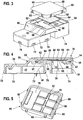
- FIG. 1 is the exploded view of a first embodiment of the inventively proposed pressure equalization unit (integrated in the lid of a tank pressure sensor) refer.
- FIG. 1 shows a housing cover 12 of a tank pressure sensor having a number of locking lugs 14. With these, the housing cover 12 is clamped in a tank pressure sensor.
- the housing cover 12 comprises a dome-shaped elevation 16.
- the dome-shaped elevation 16 is delimited by a planar surface 18 configured here in a circular manner.
- On the circumference of the dome-shaped elevation 16 extend a number of arc-shaped locking segments 20, which are separated from each other by an interruption 22 in the circumferential direction.
- an air opening 24 In the plane surface 18 of the dome-shaped elevation 16 is also an air opening 24.
- the housing cover 12 is one of the pressure compensation components of the pressure compensation unit 10th
- a filter membrane 26 is glued, which is preferably designed as a water-repellent and liquid-impermeable filter membrane. This serves to protect the interior of the tank pressure sensor against liquid media and dust. Thus, irrespective of the installation position of the housing cover 12 of a tank pressure sensor, the penetration of spray water and other liquid or solid media into the housing of the tank pressure sensor can be prevented.
- the adhered to the flat surface 18 of the dome-shaped elevation 16 filter membrane 26 is protected by a snap-on segments 20, which are formed on the circumference of the dome-shaped elevation 16, latchable cap-shaped cover member 28.
- the cap-shaped cover member 28 protects the glued, water-repellent, liquid-impermeable, but gas-permeable filter membrane 26 against environmental influences and mechanical damage.
- the cap-shaped cover member 28 has no points of contact with the filter membrane 26 and its bonding to the flat surface 18 of the dome-shaped elevation 16.
- a cap-shaped cover element 28 forms a gap width 34 in the region of a catch 32, which is formed by the latching segments 20 on the circumference of the dome-shaped elevation 16 and the inside of the cap-shaped cover element 28.
- Reference numeral 30 designates an air flow which represents from outside to inside. From the illustration according to FIG. 2 It is apparent that the glued on top of the flat surface 18 Filter membrane 26 is acted upon by the gap 34 to ambient pressure and on the other hand from the inside of the dome-shaped elevation 16 forth, ie through the air opening 24 in the dome-shaped elevation 16 with the ruling within a reference space 40 of the tank pressure sensor pressure levels.
- the serving as a pressure compensation element, water-repellent, liquid-impermeable, but gas-permeable filter membrane 26 allows rapid pressure equalization between the environment and the reference space 40.
- By capped on the locking segments 20 of the dome-shaped elevation 16 cover 28 is bonded to the flat surface 18 filter membrane 26 against mechanical overload , such as impinging water, reliably protected.
- the air flow area of the filter membrane 26 is dimensioned to be larger than the area of the air opening 24.
- FIG. 3 is an exploded view of another embodiment of the inventively proposed pressure compensation unit shown.
- FIG. 3 shows a further housing cover 50 which on the one hand has an inlet opening 74, is present at the ambient pressure level, and on the other hand, a wall 72, on which a number of clamping lugs 70 are executed. With these, the further housing cover 50 is clamped to the housing of a tank pressure sensor.
- the further housing cover 50 includes a recess 52.
- the recess 52 is bounded on the one hand by a circumferentially extending wall 54 and on the other hand by a bottom 56.
- In the bottom 56 is an opening 60 which is divided by a web 58.
- In the bottom 56 of the recess 52 is further at least one air hole 62.
- a filter membrane 64 is glued to the bottom 56 at the edge of the opening 60.
- the preferably water-repellent and liquid impermeable trained filter membrane 64 is supported by the web 58 and on the other hand protected by the inside of the wall 54 of the other housing cover 50 verklemmbare cap-shaped cover member 66.
- the cap-shaped cover member 66 comprises at its periphery a number of clamping lugs 68, via which the cap-shaped cover member 66 in the recess 52 defining wall 54 can be latched.
- the cap-shaped cover 66 may also - as in FIG. 3 indicated - fixed by gluing 67 on the other housing cover 50.
- FIG. 4 shows a side view of the representation of the air duct in the pressure compensation unit according to the exploded view in FIG. 3 ,
- FIG. 4 It can be seen that the cap-shaped cover member 66 in the recess 52 (see illustration according to FIG. 3 ) is clamped and abuts with its clamping lugs 68 on the inside of the recess 52 bounding wall 54. Above the opening 60 in the further cover 50 is the filter membrane 64. Above the filter membrane 64, the cap-shaped cover member 66 extends. As shown in FIG. 4 can be removed, the air flow 30, starting from the inlet opening 74, passes through the gas-permeable filter membrane 64, via channels 80, 82, through air holes 62 in the reference pressure chamber 40 of the tank pressure sensor. The gap 84 is delimited between the further housing cover 50 and the inner side 78 of the cap-shaped cover element 66.
- the gas-permeable filter membrane 64 covering the opening 60 together with the web 58, which serves as a pressure compensation element, pressure equalization is possible between the ambient pressure present at the inlet opening 74 of the further housing cover 50 and the pressure level present in the reference space 40.
- FIG. 4 It can be seen, which reproduces the cap-shaped cover member 66 clamped in the recess 52 and glued state, the filter membrane 64 is effectively protected against both mechanical damage and overloading by impinging on this spray water.
- the position of the cap-shaped cover member 66 allows the air flow 30, starting from the inlet opening 74, through the gas-permeable filter membrane 64 in the direction of the gap 84.
- the cap-shaped cover 66 is preferably glued along its circumference in the recess 52 at the top of the other housing cover 50, compare reference numeral 67 in FIG FIG. 4 ,
- the cap-shaped cover 66 is located with elevations 81 which are formed on its inner side 78, directly on the filter membrane 64 (see illustration according to FIG. 5 ).
- FIG. 5 shows a perspective view of the inside of the cap-shaped cover member 66 as shown in the FIGS. 3 and 4 ,
- the cap-shaped cover member 66 which is preferably manufactured as an injection-molded component, has at its periphery a number of clamping lugs 68. By means of the clamping lugs 68, the cap-shaped cover member 66 is positioned within the wall 54 of the recess 52. Air ducts 80, 82 extend on an inner side 78 of the cap-shaped cover element 66. The air ducts designated by reference numeral 80 extend in the longitudinal direction, ie parallel to the web 58, which is embodied within the opening 60 in the bottom 56 of the recess 52 in the housing part 50.
- Reference numeral 82 denotes an air channel on the inner side 78 of the cap-shaped cover member 66, which extends in the transverse direction and which connects the air ducts 80 which extend in the longitudinal direction with each other.
- Surveys 81 are areas in the area of FIG. 4 shown installation state of the cap-shaped cover 66 rest directly on the top of the filter membrane 64.
- An airtight connection of the cap-shaped cover member 66 within the recess 52 with the other housing cover 50 is effected by a bond 67 along the circumference of the cap-shaped cover 66. Due to an airtight connection thus produced, a pressure equalization between the reference pressure chamber 40 and the atmosphere only via that of the Filter membrane 64 covered opening 60 to the reference pressure chamber 40th
- FIG. 4 illustrated air guide 30 when the cap 66 is positioned and bonded in the recess 52 of the further housing cover 50.
- the air guide 30 runs in the installed state of the cap-shaped cover 66 above the gas-permeable designed filter membrane 64 in the direction of FIG. 4 illustrated gap 84 between the other housing cover 50 and the inside 78 of the airtightly installed in the recess 52 cap-shaped cover 66th
- the in FIG. 4 shown further cover 50 produced by means of plastic injection molding.
- the inlet opening 74 can be injected in a single operation as well as the recess 52 for receiving the cap-shaped cover 66.
- the Luflöticianen 62 the opening 60 dividing web 58, the clamping lugs 70, the wall 54, the bottom 56 of the recess 52 can be made in one step.
- the sectional view according to FIG. 4 shows that a wall 36 of the further housing cover 50 and the cap-shaped cover 66 may be designed according to mechanical requirements in different thicknesses.
- the filter membrane 26 from below by the dome-shaped elevation 16 to load, for example spray, protected and excluded the closing of the air opening 24 by water due to the water-repellent filter membrane; in the in the FIGS. 3, 4 and 5 shown second variant of the variant of the present invention proposed pressure compensation unit 10, the filter membrane 26 is protected by the hermetically sealed in the recess 52 cap-shaped cover 66 against overload and accumulating spray water.
- the tank pressure sensor according to the in the FIGS. 3 and 4 illustrated second embodiment variant is to be installed so that the open inlet opening 74 is not facing up.
- 3, 4 and 5 illustrated second embodiment variant of the inventively proposed pressure compensation unit is preferably installed so that the provided on the inside 78 with the air channels 80, 82 cap 66 is up and covers the underlying filter membrane 64, and an accumulation of water in the inlet opening and the To avoid icing there.
- the inventively proposed pressure compensation unit described in more detail above from export forms ensures that liquid media does not accumulate on the filter membranes 26, 64 and thus cause icing, in particular the air opening 60.
- the filter membrane 26, 64 is effectively protected by the cap 28, 66 from above against load, for example, splashed water.
- the surface of the filter membrane 26, 64 can be considerably increased by the solution proposed by the invention, whereby water can not wet the opening 24, 60 and the filter membrane 26, 64. This can avoid that the opening 24, 60 is closed by freezing water.
Landscapes
- Physics & Mathematics (AREA)
- General Physics & Mathematics (AREA)
- Measuring Fluid Pressure (AREA)
Description
-
US 5,661,244 bezieht sich auf einen Drucksensor, der zur Messung des Druckes eines Kraft-stofftanks eingesetzt wird. Der Drucksensor umfasst eine Druckzuführleitung aus metallischem Material, welche in den Druckeinlass eines metallischen Gehäuses eingebracht ist und dort durch Schweißen fixiert ist. Das Gehäuse umfasst einen Flanschabschnitt im oberen Bereich, wobei der Flanschabschnitt mit einer äußeren Wand eines Tanks verbunden ist, der das zu messende Objekt darstellt, derart, dass sich der Drucksensor auf der Innenseite des Tanks befindet. Ein poröser Filter, der aus einem fluoroplastischen Kunststoffhergestellt ist, ist neben einem Atmosphärendruckeinlass angeordnet. Ein Klebeband ist am Atmosphärendruckeinlass lösbar befestigt. Der Drucksensor erlaubt einen sicheren Betrieb und eine sehr hohe Zuverlässigkeit hinsichtlich des Luftabschlusses für ein Sensorelement, weniger Beschränkungen hinsichtlich der Auslegung des Sensors für kleine Räume und vermeidet zuverlässig das Eintreten von Luft und Wasser bzw. Staub in das Innere des Sensors. Eine andere Anordnung wird z.B. im DokumentUS 5 692 637 beschrieben. - Druckausgleichskomponenten werden innerhalb eines Tankdrucksensors verbaut und dienen dem Ausgleich eines Druckunterschiedes zwischen einem Referenzraum des Tankdrucksensors und der Umgebung. Der Tankdruck wird von unten an die Rückseite einer Siliziummembran geführt, während der in der Umgebung herrschende Druck als Referenzdruck von oben, so zum Beispiel durch eine Öffnung im Sensorgehäuse, auf die Vorderseite der Siliziummembran einwirkt. Um die Vorderseite der Siliziummembran gegen Wasser zu schützen, ist eine gaspenneable Filtermembran in eine Referenzdrucköffnung eingebaut. Die gaspermeabel ausgestaltete Filtermembran dient als Druckausgleichselement. Das Druckausgleichselement ist in der Regel wasserabweisend und flüssigkeitsundurchlässig ausgebildet und dient der Abdichtung der Referenzdrucköffhung des Tankdrucksensors der Tankeinbaueinheit gegen Flüssigkeiten. Durch diese Lösung soll unabhängig von der Einbaulage des Druckausgleichselementes das Eindringen von Spritzwasser sowie anderen flüssigen oder festen Medien in den Sensorraum unterbunden werden.
- Der vorliegenden Erfindung liegt die Aufgabe zugrunde, eine Filtermembran eines Differenzdrucksensors gegen Überlast zu schützen und gleichzeitig einen schnellen Druckausgleich zwischen der Umgebung und einem Sensorinnenraum herbeizuführen.
- Der erfindungsgemäß vorgeschlagenen Lösung folgend wird ein Gehäusedeckel mit integriertem Dom als Träger für eine Filtermembran eingesetzt. Die Filtermembran wird bevorzugt scheibenförmig ausgebildet und auf die im Gehäusedeckel integrierte, dort ausgebildete domförmige Erhebung vorzugsweise zentrisch aufgeklebt. Eine in der domförmigen Erhebung ausgeführte Durchführung gewährleistet die Verbindung eines Referenzdruckvolumens im Sensorinnenraum mit der diesen umgebenden Atmosphäre. Mittels einer an der im Gehäusedeckel ausgebildeten domförmigen Erhebung verrastbaren Kappe wird die aufgeklebte Filtermembran gegen Umwelteinflüsse abgeschirmt, sowie gegen mechanische Beschädigungen geschützt. Die an der domförmigen Erhebung, die im Gehäusedeckel ausgebildet ist, zu verrastende Kappe dient der Abschirmung der Filtermembran. Die an der domförmigen Erhebung integrierte Kappe weist keinerlei Berührungspunkte zur Filtermembran und deren Verklebung an der domförmigen Erhebung auf. Diese Aus führungs variante zeichnet sich dadurch aus, dass die zentrisch aufgeklebte Filtermembran von unten durch die domförmige Erhebung gegenüber Last, wie zum Beispiel Wasser, geschützt ist. Des Weiteren wird durch diese Aus führungs variante des der Erfindung zugrunde liegenden Gedankens gewährleistet, dass vermieden wird, dass eine Referenzluftbohrung durch eingetretene Schmutzpartikel verschlossen ist, oder sich der Innenraum des Tankdrucksensors mit Wasser füllt.
- In einer weiteren Aus führungs form des der Erfindung zugrunde liegenden Gedankens dient ein Gehäusedeckel als Träger für die Filtermembran. Die vorgeschlagene Filtermembran, die bevorzugt wasserabweisend und flüssigkeitsundurchlässig ausgebildet ist, wird an ihrem Rand auf den Gehäusedeckel aufgeklebt, wobei die Filtermembran durch eine Kappe geschützt ist. Ein im Gehäusedeckel ausgebildeter Steg verhindert ein Durchhängen der flächigen Filtermembran. In einer die Filtermembran von oben her schützenden Kappe sind Kanäle ausgeführt. Die Kappe liegt flächig direkt auf der Filtermembran auf und stützt somit die Filtermembran ab. Die Kanäle sorgen für einen ausreichenden Luftdurchlass, um Druckunterschiede zwischen der Umgebung und einem Referenzraum des Sensors zu gewährleisten. Im Gehäusedeckel, der als Träger für die Filtermembran dient, sind Öffnungen ausgebildet, welche eine Verbindung eines Referenzdruckvolumens im Sensorinnenraum mit der diese umgebenden Atmosphäre gewährleisten. Für diese Aus führungs variante ist es günstig, den Einbauort der Druckausgleichseinheit so zu wählen, dass die freie Filtermembran durch den Einbauort und die Einbaulage zusätzlich geschützt ist.
- Die Vorteile der obenstehend beschriebenen zweiten Aus führungs form des der Erfindung zugrunde liegenden Gedankens liegen darin, dass flüssige Medien sich nicht auf der Filtermembran ansammeln und damit zu einer Vereisung der Referenzluftöffuung fuhren. Die in der alternativen Aus führungs variante eingesetzte, am Gehäusedeckel im Randbereich verklebte Filtermembran wird durch ein kappenförmiges Abdeckelement von oben gegen Überlast geschützt. Des Weiteren zeichnet sich die erfindungsgemäß vorgeschlagene Druckausgleichseinheit durch eine größere Fläche und einen dadurch gegebenen besseren Druckausgleich im Referenzraum aus.
- Anhand der Zeichnungen wird die Erfindung nahestehend eingehender beschrieben. Es zeigt
- Figur 1
- eine Explosionsdarstellung einer ersten Ausführungsform der erfindungs gemäß vorgeschlagenen Druckausgleichseinheit, integriert im Deckel eines Tankdrucksensors,
- Figur 2
- eine Darstellung der Druckausgleichseinheit mit Wiedergabe eines Luftführungspfades,
- Figur 3
- eine Explosionsdarstellung einer weiteren Aus führungs variante der erfindungsgemäß vorgeschlagenen Druckausgleichseinheit, integriert im Deckel eines Tankdrucksensors,
- Figur 4
- die sich einstellende Luftdurchführung bei montiertem kappenförmigem Verschlusselement und
- Figur 5
- eine perspektivische Ansicht der Innenseite des kappenförmigen Verschlusselementes.
- Der Darstellung gemäß
Figur 1 ist die Explosionsdarstellung einer ersten Ausführungsform der erfindungsgemäß vorgeschlagenen Druckausgleichseinheit (integriert im Deckel eines Tankdrucksensors) zu entnehmen. -
Figur 1 zeigt einen Gehäusedeckel 12 eines Tankdrucksensors, der eine Anzahl von Rastnasen 14 aufweist. Mit diesen ist der Gehäusedeckel 12 in einem Tankdrucksensor geklemmt. Der Gehäusedeckel 12 umfasst eine domförmig ausgebildete Erhebung 16. Die domförmige Erhebung 16 ist durch eine hier kreisförmig ausgestaltete Planfläche 18 begrenzt. Am Umfang der domförmigen Erhebung 16 verlaufen eine Anzahl von kreisbogenförmig ausgebildeten Rastsegmenten 20, die jeweils durch eine Unterbrechung 22 in Umfangsrichtung voneinander getrennt sind. In der Planfläche 18 der domförmigen Erhebung 16 befindet sich außerdem eine Luftöffnung 24. Der Gehäusedeckel 12 gehört zu den Druckausgleichskomponenten der Druckausgleichseinheit 10. - Auf die Planfläche 18 der domförmigen Erhebung wird eine Filtermembran 26 aufgeklebt, die bevorzugt als wasserabweisende und flüssigkeitsundurchlässige Filtermembran ausgebildet ist. Diese dient zum Schutz des Innenraumes des Tankdrucksensors gegen flüssige Medien und Staub. Damit kann unabhängig von der Einbaulage des Gehäusedeckels 12 eines Tankdrucksensors das Eindringen von Spritzwasser sowie anderen flüssigen oder festen Medien in das Gehäuse des Tankdrucksensors unterbunden werden.
- Die auf die Planfläche 18 der domförmigen Erhebung 16 aufgeklebte Filtermembran 26 wird durch ein an den Rastsegmenten 20, die am Umfang der domförmigen Erhebung 16 ausgebildet sind, verrastbares kappenförmiges Abdeckelement 28 geschützt. Das kappenförmige Abdeckelement 28 schützt die aufgeklebte, wasserabweisende, flüssigkeitsundurchlässige, jedoch gaspermeable Filtermembran 26 gegen Umwelteinflüsse sowie mechanische Beschädigungen. Das kappenförmige Abdeckelement 28 weist keine Berührpunkte zur Filtermembran 26 und deren Verklebung an der Planfläche 18 der domförmigen Erhebung 16 auf.
- Wie aus der Darstellung gemäß
Figur 2 hervorgeht, bildet sich bei an der domförmigen Erhebung 16 verrastetem kappenförmigen Abdeckelement 28 im Bereich einer Verrastung 32, die durch die Rastsegmente 20 am Umfang der domförmigen Erhebung 16 und der Innenseite des kappenförmigen Abdeckelementes 28 gebildet wird, eine Spaltweite 34 aus. Mit Bezugszeichen 30 ist eine sich von außen nach innen darstellende Luftströmung gekennzeichnet. Aus der Darstellung gemäßFigur 2 geht hervor, dass die auf der Oberseite der Planfläche 18 aufgeklebte Filtermembran 26 durch den Spalt 34 mit Umgebungsdruck beaufschlagt ist und andererseits von der Innenseite der domförmigen Erhebung 16 her, d. h. durch die Luftöffnung 24 in der domförmigen Erhebung 16 mit den innerhalb eines Referenzraumes 40 des Tankdrucksensors herrschenden Druckniveaus. - Die als Druckausgleichselement dienende, wasserabweisende, flüssigkeitsundurchlässige, jedoch gaspermeable Filtermembran 26 ermöglicht einen schnellen Druckausgleich zwischen der Umgebung und dem Referenzraum 40. Durch das an den Rastsegmenten 20 der domförmigen Erhebung 16 kappenförmige Abdeckelement 28 ist die an der Planfläche 18 verklebte Filtermembran 26 gegen mechanische Überlastung, wie zum Beispiel auftreffendes Wasser, zuverlässig geschützt. Ferner wird durch das an den Rastsegmenten 20 im Rahmen der Verrastung 32 lösbar befestigte kappenförmige Abdeckelement 28 sichergestellt, dass keine Partikel oder Ähnliches die Filtermembran 26 beschädigen können sowie keine Partikel oder dergleichen durch die Lufteintrittsöffliung 24 in den Referenzraum 40 des Tankdrucksensors gelangen. Die Luftdurchflussfläche der Filtermembran 26 ist größer bemessen als die Fläche der Luftöffnung 24.
- Des Weiteren wird durch die Lösung gemäß der ersten Aus führungs variante, wie in den
Figuren 1 und 2 dargestellt, verhindert, dass die Luftöffnung 24 zwischen dem Referenzdruckraum 40 des Tankdrucksensors und der Umgebung, zum Beispiel durch einen sich dort anlagernden Wassertropfen, verschlossen wird, so dass kein Druckausgleich zwischen der Umgebung und dem Referenzdruckraum 40 des Tankdrucksensors stattfinden kann. - In der Darstellung gemäß
Figur 3 ist eine Explosionsdarstellung einer weiteren Ausführungsvariante der erfindungsgemäß vorgeschlagenen Druckausgleichseinheit gezeigt. -
Figur 3 zeigt einen weiteren Gehäuseedeckel 50, welcher einerseits eine Einlassöffnung 74 auf weist, an der Umgebungsdruckniveau ansteht, und andererseits eine Wand 72 aufweist, an welcher eine Anzahl von Klemmnasen 70 ausgeführt sind. Mit diesen ist der weitere Gehäusedeckel 50 am Gehäuse eines Tankdrucksensors geklemmt. - Der weitere Gehäusedeckel 50 gemäß der Explosionsdarstellung in
Figur 3 umfasst eine Vertiefung 52. Die Vertiefung 52 ist einerseits von einer sich in Umfangsrichtung erstreckenden Wandung 54 und andererseits von einem Boden 56 begrenzt. Im Boden 56 befindet sich eine Öffnung 60, die durch einen Steg 58 geteilt ist. Im Boden 56 der Vertiefung 52 befindet sich ferner mindestens ein Luftloch 62. Eine Filtermembran 64 wird am Rand der Öffnung 60 auf den Boden 56 aufgeklebt. Die bevorzugt wasserabweisend und flüssigkeitsundurchlässig ausgebildete Filtermembran 64 wird durch den Steg 58 abgestützt und andererseits durch das innerhalb der Wandung 54 des weiteren Gehäusedeckels 50 verklemmbare kappenförmige Abdeckelement 66 geschützt. Das kappenförmige Abdeckelement 66 umfasst an ihrem Umfang eine Anzahl von Klemmnasen 68, über welche das kappenförmige Abdeckelement 66 in der die Vertiefung 52 begrenzenden Wandung 54 verrastbar ist. Das kappenförmige Abdeckelement 66 kann zudem - wie inFigur 3 angedeutet - durch Verklebungen 67 am weiteren Gehäusedeckel 50 befestigt werden. -
Figur 4 zeigt eine Seitenansicht der Darstellung der Luftführung in der Druckausgleichseinheit gemäß der Explosionsdarstellung inFigur 3 . -
Figur 4 ist zu entnehmen, dass das kappenförmige Abdeckelement 66 in der Vertiefung 52 (vergleiche Darstellung gemäßFigur 3 ) geklemmt ist und mit ihren Klemmnasen 68 an der Innenseite der die Vertiefung 52 begrenzenden Wandung 54 anliegt. Oberhalb der Öffnung 60 im weiteren Deckel 50 befindet sich die Filtermembran 64. Oberhalb der Filtermembran 64 erstreckt sich das kappenförmige Abdeckelement 66. Wie der Darstellung gemäßFigur 4 entnommen werden kann, verläuft die Luftströmung 30, ausgehend von der Einlassöffnung 74, durch die gaspermeabel ausgebildete Filtermembran 64, über Kanäle 80, 82, durch Luftlöcher 62 in den Referenzdruckraum 40 des Tankdrucksensors. Der Spalt 84 ist zwischen dem weiteren Gehäusedeckel 50 und der Innenseite 78 des kappenförmigen Abdeckelementes 66 begrenzt. Durch die die Öff-nung 60 samt Steg 58 abdeckende gaspermeable Filtermembran 64, die als Druckausgleichselement dient, ist ein Druckausgleich zwischen dem an der Einlassöffnung 74 des weiteren Gehäusedeckels 50 anstehenden Umgebungsdruck und dem im Referenzraum 40 anstehenden Druckniveau möglich. Wie aus der Darstellung gemäßFigur 4 hervorgeht, welche das kappenförmige Abdeckelement 66 im in der Vertiefung 52 geklemmten und verklebten Zustand wiedergibt, ist die Filtermembran 64 sowohl gegen mechanische Beschädigung als auch gegen Überlastung durch auf diese auftreffendes Spritzwasser wirksam geschützt. Die Lage des kappenförmigen Abdeckelementes 66 ermöglicht die Luftströmung 30, ausgehend von der Einlassöffnung 74, durch die gaspermeable Filtermembran 64 in Richtung des Spaltes 84. Das kappenförmige Abdeckelement 66 ist bevorzugt entlang seines Umfangs in die Vertiefung 52 an der Oberseite des weiteren Gehäusedeckels 50 eingeklebt, vergleiche Bezugszeichen 67 inFigur 4 . Das kappenförmige Abdeckelement 66 liegt mit Erhebungen 81, die an ihrer Innenseite 78 ausgebildet sind, direkt auf der Filtermembran 64 auf (vergleiche Darstellung gemäßFigur 5 ). -
Figur 5 zeigt eine perspektivische Ansicht der Innenseite des kappenförmigen Abdeckelementes 66 gemäß der Darstellung in denFiguren 3 und 4 . - Das kappenförmige Abdeckelement 66, das bevorzugt als Spritzgussbauteil gefertigt ist, weist an seinem Umfang eine Anzahl von Klemmnasen 68 auf. Mittels der Klemmnasen 68 ist das kappenförmige Abdeckelement 66 innerhalb der Wandung 54 der Vertiefung 52 positioniert. An einer Innenseite 78 des kappenförmigen Abdeckelementes 66 erstrecken sich Luftkanäle 80, 82. Die mit Bezugszeichen 80 bezeichneten Luftkanäle erstrecken sich in Längsrichtung, d. h. parallel zum Steg 58, der innerhalb der Öffnung 60 im Boden 56 der Vertiefung 52 im Gehäuseteil 50 ausgeführt ist. Mit Bezugszeichen 82 ist ein Luftkanal an der Innenseite 78 des kappenförmigen Abdeckelementes 66 bezeichnet, der sich in Querrichtung erstreckt und der die Luftkanäle 80, die sich in Längsrichtung erstrecken, miteinander verbindet. Durch die Luftkanäle 80, 82 werden an der Innenseite 78 erhaben über diese hervorstehende Erhebungen 81 voneinander getrennt. Bei den Erhebungen 81 handelt es sich um flächige Bereiche, die im in
Figur 4 dargestellten Einbauzustand des kappenförmigen Abdeckelementes 66 direkt auf der Oberseite der Filtermembran 64 aufliegen. Eine luftdichte Verbindung des kappenförmigen Abdeckelementes 66 innerhalb der Vertiefung 52 mit dem weiteren Gehäusedeckel 50 erfolgt durch eine Verklebung 67 entlang des Umfangs des kappenförmigen Abdeckelementes 66. Aufgrund einer derart hergestellten luftdichten Verbindung erfolgt ein Druckausgleich zwischen dem Referenzdruckraum 40 und der Atmosphäre nur über die von der Filtermembran 64 abgedeckte Öffnung 60 zum Referenzdruckraum 40. - Aufgrund der Gestaltung der Innenseite 78 der kappenförmigen Abdeckung 66 - wie in
Figur 5 dargestellt - ergibt sich die Möglichkeit der inFigur 4 dargestellten Luftführung 30, wenn die Kappe 66 in der Vertiefung 52 des weiteren Gehäusedeckels 50 positioniert und verklebt ist. Über die Luftkanäle 80, 82 an der Innenseite 78 der kappenförmigen Abdeckung 66 verläuft die Luftführung 30 im verbauten Zustand der kappenförmigen Abdeckung 66 oberhalb der gaspermeabel ausgeführten Filtermembran 64 in Richtung des inFigur 4 dargestellten Spaltes 84 zwischen dem weiteren Gehäusedeckel 50 und der Innenseite 78 der in der Vertiefung 52 luftdicht verbauten kappenförmigen Abdeckung 66. - Ebenso wie die kappenförmige Abdeckung 66 wird auch der in
Figur 4 dargestellte weitere Deckel 50 im Wege des Kunststoffspritzgießverfahrens hergestellt. Dies bedeutet, dass am weiteren Deckel 50 der erfindungsgemäß vorgeschlagenen Druckausgleichseinheit 10 die Einlassöffnung 74 in einem Arbeitsgang ebenso wie die Vertiefung 52 zur Aufnahme der kappenförmigen Abdeckung 66 gespritzt werden kann. Bei der Fertigung des weiteren Gehäusedeckels 50 im Wege des Kunststoffspritzgießverfahrens können die Luflöffnungen 62, der die Öffnung 60 teilende Steg 58, die Klemmnasen 70, die Wandung 54, der Boden 56 der Vertiefung 52 in einem Arbeitsschritt gefertigt werden. Die Schnittdarstellung gemäßFigur 4 zeigt, dass eine Wand 36 des weiteren Gehäusedeckels 50 und die kappenförmige Abdeckung 66 je nach mechanischen Anforderungen in unterschiedlichen Dicken ausgelegt sein können. - In der in den
Figuren 1 und 2 dargestellten ersten Aus führungs variante der erfindungsgemäß vorgeschlagenen Druckausgleichseinheit ist die Filtermembran 26 von unten durch die domförmige Erhebung 16 gegenüber Last, zum Beispiel Spritzwasser, geschützt und das Verschließen der Luftöffnung 24 durch Wasser aufgrund der wasserabweisenden Filtermembran ausgeschlossen; in der in denFiguren 3, 4 und 5 dargestellten zweiten Aus führungs variante der erfindungsgemäß vorgeschlagenen Druckausgleichseinheit 10 ist die Filtermembran 26 durch die in der Vertiefung 52 luftdicht verbaute kappenförmige Abdeckung 66 gegen Überlast und sich ansammelndes Spritzwasser geschützt. Der Tankdrucksensor gemäß der in denFiguren 3 und 4 dargestellten zweiten Aus führungs variante ist so einzubauen, dass die offene Einlassöffnung 74 nicht nach oben zeigt. Die in denFiguren 3, 4 und 5 dargestellte zweite Aus führungs variante der erfindungsgemäß vorgeschlagenen Druckausgleichseinheit wird bevorzugt so eingebaut, dass die an der Innenseite 78 mit den Luftkanälen 80, 82 versehene Kappe 66 nach oben steht und die darunter liegende Filtermembran 64 abdeckt, und ein Ansammeln von Wasser in der Einlassöffnung und dessen Vereisung dort zu vermeiden. - Die erfindungsgemäß vorgeschlagene Druckausgleichseinheit in obenstehend eingehender beschriebenen Aus fuhrungs formen gewährleistet, dass flüssige Medien sich nicht auf den Filtermembranen 26, 64 ansammeln und damit eine Vereisung, insbesondere der Luftöffnung 60, bewirken. Die Filtermembran 26, 64 wird durch die Kappe 28, 66 von oben gegenüber Last, zum Beispiel auftreffendes Spritzwasser, wirksam geschützt. Des Weiteren kann durch die erfindungsgemäß vorgeschlagene Lösung die Fläche der Filtermembran 26, 64 erheblich vergrößert werden, wodurch Wasser die Öffnung 24, 60 und die Filtermembran 26, 64 nicht benetzen kann. Dadurch kann vermieden werden, dass die Öffnung 24, 60 durch gefrierendes Wasser verschlossen wird.
Claims (10)
- Druckausgleichseinheit (10) für einen Differenzdrucksensor, insbesondere für einen Tankdrucksensor eines Kraftfahrzeuges, mit einem Gehäusedeckel (12, 50) und einer gaspermeablen Filtermembran (26, 64), die eine Luftöffnung (24, 60) des Gehäusedeckels überdeckt, dadurch gekennzeichnet, dass die gaspermeable Filtermembran (26, 64) von einem kappenförmigen Abdeckelement (28, 66) überdeckt, welches mit dem Gehäusedeckel (12,50) der Druckausgleichseinheit verbindbar ist und wobei die Filtermembran (26) durch eine domförmige Erhebung (16) des Gehäusedeckels (12), an der das kappenförmige Abdeckelement (28) verrastbar ist, gestützt ist oder die Luftöffnung (60, 62) im Boden (56) einer Vertiefung (52) im Gehäusedeckel (50) ausgeführt ist, in der ein kappenförmiges Abdeckelement (66) luftdicht eingeklebt (67) ist und an einer Innenseite (78) des kappenförmigen Abdeckelementes (66) Kanäle (80, 82) zur Luftdurchführung (30) ausgeführt sind und an der Innenseite (78) die Filtermembran (64) abstützende Erhebungen (81) ausgeführt sind.
- Druckausgleichseinheit (10) gemäß Anspruch 1, dadurch gekennzeichnet, dass die Filtermembran (26, 64) aus einem wasserabweisenden, flüssigkeitsundurchlässigen Material gefertigt ist.
- Druckausgleichseinheit (10) gemäß Anspruch 1, dadurch gekennzeichnet, dass die Filtermembran (26) auf einer Planfläche (18) einer domförmigen Erhebung (16) befestigt ist, an der das kappenförmige Abdeckelement (28) verrastbar ist.
- Druckausgleichseinheit (10) gemäß Anspruch 3, dadurch gekennzeichnet, dass am Umfang der domförmigen Erhebung (16) Rastsegmente (20) vorgesehen sind, die in Umfangsrichtung durch Unterbrechungen (22) voneinander getrennt sind, die eine Spaltweite (34) für eine Luftströmung (30) bilden.
- Druckausgleichseinheit (10) gemäß Anspruch 3, dadurch gekennzeichnet, dass im verrasteten Zustand (32) des kappenförmigen Abdeckelementes (28) die Filtermembran (26) geschützt ist und deine Verbindung zwischen einem Referenzdruckraum (40) und der Umgebung besteht, und ein Verschluss durch Verunreinigung und/oder Flüssigkeiten vermieden wird.
- Druckausgleichseinheit (10) gemäß Anspruch 1, dadurch gekennzeichnet, dass der Gehäusedeckel (50) eine Luftöffnung (60) zur Atmosphäre aufweist, die durch die Filtermembran (64) überdeckt ist sowie mindestens eine Öffnung (62) zu dem Referenzdruckraum (40).
- Druckausgleichseinheit (10) gemäß Anspruch 1, dadurch gekennzeichnet, dass im in der Vertiefung (52) verbauten Zustand des kappenförmigen Abdeckelementes (66) die Kanäle (80, 82) an der Innenseite (78) des kappenförmigen Abdeckelementes (66) die Luftdurchführung (30) von der Einlassöffnung (74) zu der mindestens einen Öffnung (62) in den Referenzdruckraum (40) vornehmen.
- Druckausgleichseinheit (10) gemäß Anspruch 1, dadurch gekennzeichnet, dass die Filtermembran (64) durch die Erhebungen (81) an der Innenseite (78) abgestützt ist und ein Luftdurchlass durch die Kanäle (80, 82) erfolgt.
- Druckausgleichseinheit (10) gemäß Anspruch 5, dadurch gekennzeichnet, dass die Filtermembran (26) durch direkte Anlage an der Planfläche (18) gegen Überlast abgestützt ist und ein Luftdurchfluss durch eine Luftöffnung (24) erfolgt.
- Verwendung der Druckausgleichseinheit (10) gemäß einem oder mehreren der vorhergehenden Ansprüche in Verbindung mit einem Tankdrucksensor, insbesondere im Kraftstofftank eines Kraftfahrzeuges.
Applications Claiming Priority (2)
| Application Number | Priority Date | Filing Date | Title |
|---|---|---|---|
| DE102008004358A DE102008004358A1 (de) | 2008-01-15 | 2008-01-15 | Druckausgleichseinheit |
| PCT/EP2008/066549 WO2009089959A1 (de) | 2008-01-15 | 2008-12-01 | Druckausgleichseinheit |
Publications (3)
| Publication Number | Publication Date |
|---|---|
| EP2235490A1 EP2235490A1 (de) | 2010-10-06 |
| EP2235490B1 true EP2235490B1 (de) | 2016-05-04 |
| EP2235490B2 EP2235490B2 (de) | 2020-02-12 |
Family
ID=40626767
Family Applications (1)
| Application Number | Title | Priority Date | Filing Date |
|---|---|---|---|
| EP08870875.5A Active EP2235490B2 (de) | 2008-01-15 | 2008-12-01 | Druckausgleichseinheit |
Country Status (5)
| Country | Link |
|---|---|
| US (1) | US8413496B2 (de) |
| EP (1) | EP2235490B2 (de) |
| CN (1) | CN101910813B (de) |
| DE (1) | DE102008004358A1 (de) |
| WO (1) | WO2009089959A1 (de) |
Families Citing this family (26)
| Publication number | Priority date | Publication date | Assignee | Title |
|---|---|---|---|---|
| DE102008001393A1 (de) * | 2008-04-25 | 2009-10-29 | Robert Bosch Gmbh | Luftdrucksensor zur Aufprallerkennung |
| DE102009003149A1 (de) | 2009-05-15 | 2010-11-18 | Robert Bosch Gmbh | Druckausgleichseinheit zur Verwendung in einem Drucksensor |
| FR2950691B1 (fr) * | 2009-09-30 | 2012-05-04 | Michelin Soc Tech | Organe de mesure de pression etanche |
| US8375778B2 (en) * | 2010-02-22 | 2013-02-19 | Delphi Technologies, Inc. | Sealed engine control module with integral ambient air pressure sensor |
| US9146170B2 (en) * | 2012-07-31 | 2015-09-29 | Freescale Semiconductor, Inc. | Capacitive pressure sensor in an overmolded package |
| DE102012022346B4 (de) | 2012-11-15 | 2018-03-22 | Mann+Hummel Gmbh | Batterie-Gehäuse |
| DE102013208537A1 (de) * | 2012-12-27 | 2014-07-03 | Robert Bosch Gmbh | Drucksensoranordnung sowie Verfahren zum Montieren einer Drucksensoranordnung |
| DE102013015218A1 (de) * | 2013-09-13 | 2015-03-19 | Hella Kgaa Hueck & Co. | Gassensor und Kraftfahrzeug mit einem Gassensor |
| DE102014107251A1 (de) | 2014-05-22 | 2015-11-26 | Endress + Hauser Gmbh + Co. Kg | Druckausgleichselement |
| DE102015205029A1 (de) | 2015-03-19 | 2016-09-22 | Volkswagen Aktiengesellschaft | Vorrichtung zum Ausgleichen eines Innendruckes in einem geschlossenen Gehäuse |
| CN104936400B (zh) * | 2015-06-05 | 2018-08-21 | 常州华达科捷光电仪器有限公司 | 一种用于光电仪器的透气构件 |
| FR3069196B1 (fr) * | 2017-07-18 | 2021-12-24 | Plastic Omnium Advanced Innovation & Res | Dispositif de ventilation pour un reservoir de liquide de vehicule equipe d'une membrane |
| CN107456651A (zh) * | 2017-09-11 | 2017-12-12 | 珠海亿立达电子设备有限公司 | 一种用于输卵管造影的四通连接器 |
| JP6461386B1 (ja) * | 2018-01-30 | 2019-01-30 | Srdホールディングス株式会社 | 構造部材および燃料タンク |
| US11371478B2 (en) * | 2018-03-14 | 2022-06-28 | Ford Global Technologies, Llc | Systems and methods for a fuel delivery module helmet of hybrid vehicle |
| DE102018206210A1 (de) | 2018-04-23 | 2019-10-24 | Continental Automotive Gmbh | Deckelanordnung für einen Sensor sowie Fußgängerschutzsensor für ein Fahrzeug |
| FR3081672B1 (fr) | 2018-05-22 | 2021-04-09 | A Raymond Et Cie | Boitier de protection d'un dispositif electronique |
| DE102018009382A1 (de) * | 2018-11-30 | 2020-06-04 | Dräger Safety AG & Co. KGaA | Befestigungsvorrichtung für ein Sensorgehäuse |
| CN109506828A (zh) * | 2018-12-28 | 2019-03-22 | 武汉飞恩微电子有限公司 | 一种检测汽车尾气颗粒捕捉的压力传感器装置 |
| CN110967141A (zh) * | 2019-11-22 | 2020-04-07 | 南京南瑞水利水电科技有限公司 | 一种微压传感器用防水防潮气压平衡装置 |
| DE102020108442A1 (de) * | 2020-03-26 | 2021-09-30 | Kautex Textron Gmbh & Co. Kg | Batterieschale, Traktionsbatterie, Kraftfahrzeug und Verfahren zum Herstellen einer Batterieschale |
| JP7429160B2 (ja) * | 2020-05-29 | 2024-02-07 | 株式会社Fts | カバー部材 |
| DE102020131994B4 (de) * | 2020-11-17 | 2025-04-24 | Stego Holding Gmbh | Druckausgleichselement |
| JP7397030B2 (ja) * | 2021-08-25 | 2023-12-12 | 矢崎総業株式会社 | 圧力センサ |
| DE102022102445A1 (de) | 2022-02-02 | 2023-08-03 | KROHNE Pressure Solutions GmbH | Drucksensor |
| DE102024122416A1 (de) * | 2024-08-06 | 2026-02-12 | Tdk Electronics Ag | Einhausung, Bauteilanordnung, Sensoranordnung, Drucksensoranordnung und Gassensoranordnung |
Citations (14)
| Publication number | Priority date | Publication date | Assignee | Title |
|---|---|---|---|---|
| EP0377067A1 (de) | 1989-01-05 | 1990-07-11 | W.L. Gore & Associates GmbH | Sperrvorrichtung für abgedichtete Gehäuse |
| DE4133061A1 (de) | 1991-10-04 | 1993-04-15 | Bosch Gmbh Robert | Drucksensor |
| US5661244A (en) | 1994-10-05 | 1997-08-26 | Mitsubishi Denki Kabushiki Kaisha | Pressure sensor |
| US5692637A (en) | 1996-05-10 | 1997-12-02 | Delco Electronics Corporation | Vent cap for electronic package |
| US6155119A (en) | 1996-02-16 | 2000-12-05 | Ami Doduco Gmbh | Arrangement comprising an electrical printed-circuit board and an electrical pressure pick-up |
| JP2002296136A (ja) | 2001-03-30 | 2002-10-09 | Nagano Keiki Co Ltd | 変換器のケース構造 |
| WO2002090916A1 (de) | 2001-05-09 | 2002-11-14 | Endress + Hauser Gmbh + Co. Kg | Gerät mit einem ein hydrophobes oder hydrophobisiertes nanoporiges material enthaltendem feuchtfilter |
| US6575038B1 (en) | 1999-04-26 | 2003-06-10 | Denso Corporation | Pressure sensor and method for assembling the same |
| US20030220067A1 (en) | 2002-05-15 | 2003-11-27 | Nitto Denko Corporation | Ventilation member, vented housing using the same, pull-out prevention member for ventilation member and kit for forming ventilation structure |
| WO2007058206A1 (ja) | 2005-11-17 | 2007-05-24 | Nitto Denko Corporation | 通気部材 |
| JP2007155505A (ja) | 2005-12-05 | 2007-06-21 | Nagano Keiki Co Ltd | センサ装置 |
| WO2007106749A2 (en) | 2006-03-10 | 2007-09-20 | Cooper Standard Automotive, Inc. | Fluid quick connector with integrated pressure sensor |
| DE102008004696A1 (de) | 2007-01-25 | 2008-07-31 | Scania Cv Ab | Druckausgleichsventil für Flüssigkeits-, insbesondere Treibstofftanks |
| US7626129B2 (en) | 2004-07-29 | 2009-12-01 | Panasonic Corporation | Electronic apparatus |
Family Cites Families (2)
| Publication number | Priority date | Publication date | Assignee | Title |
|---|---|---|---|---|
| GB2401330B (en) * | 2003-05-09 | 2006-04-12 | Westinghouse Brakes | Pressure equalisation device |
| DE102009003149A1 (de) * | 2009-05-15 | 2010-11-18 | Robert Bosch Gmbh | Druckausgleichseinheit zur Verwendung in einem Drucksensor |
-
2008
- 2008-01-15 DE DE102008004358A patent/DE102008004358A1/de not_active Withdrawn
- 2008-12-01 WO PCT/EP2008/066549 patent/WO2009089959A1/de not_active Ceased
- 2008-12-01 CN CN200880124837.XA patent/CN101910813B/zh active Active
- 2008-12-01 US US12/735,346 patent/US8413496B2/en active Active
- 2008-12-01 EP EP08870875.5A patent/EP2235490B2/de active Active
Patent Citations (14)
| Publication number | Priority date | Publication date | Assignee | Title |
|---|---|---|---|---|
| EP0377067A1 (de) | 1989-01-05 | 1990-07-11 | W.L. Gore & Associates GmbH | Sperrvorrichtung für abgedichtete Gehäuse |
| DE4133061A1 (de) | 1991-10-04 | 1993-04-15 | Bosch Gmbh Robert | Drucksensor |
| US5661244A (en) | 1994-10-05 | 1997-08-26 | Mitsubishi Denki Kabushiki Kaisha | Pressure sensor |
| US6155119A (en) | 1996-02-16 | 2000-12-05 | Ami Doduco Gmbh | Arrangement comprising an electrical printed-circuit board and an electrical pressure pick-up |
| US5692637A (en) | 1996-05-10 | 1997-12-02 | Delco Electronics Corporation | Vent cap for electronic package |
| US6575038B1 (en) | 1999-04-26 | 2003-06-10 | Denso Corporation | Pressure sensor and method for assembling the same |
| JP2002296136A (ja) | 2001-03-30 | 2002-10-09 | Nagano Keiki Co Ltd | 変換器のケース構造 |
| WO2002090916A1 (de) | 2001-05-09 | 2002-11-14 | Endress + Hauser Gmbh + Co. Kg | Gerät mit einem ein hydrophobes oder hydrophobisiertes nanoporiges material enthaltendem feuchtfilter |
| US20030220067A1 (en) | 2002-05-15 | 2003-11-27 | Nitto Denko Corporation | Ventilation member, vented housing using the same, pull-out prevention member for ventilation member and kit for forming ventilation structure |
| US7626129B2 (en) | 2004-07-29 | 2009-12-01 | Panasonic Corporation | Electronic apparatus |
| WO2007058206A1 (ja) | 2005-11-17 | 2007-05-24 | Nitto Denko Corporation | 通気部材 |
| JP2007155505A (ja) | 2005-12-05 | 2007-06-21 | Nagano Keiki Co Ltd | センサ装置 |
| WO2007106749A2 (en) | 2006-03-10 | 2007-09-20 | Cooper Standard Automotive, Inc. | Fluid quick connector with integrated pressure sensor |
| DE102008004696A1 (de) | 2007-01-25 | 2008-07-31 | Scania Cv Ab | Druckausgleichsventil für Flüssigkeits-, insbesondere Treibstofftanks |
Also Published As
| Publication number | Publication date |
|---|---|
| WO2009089959A1 (de) | 2009-07-23 |
| EP2235490A1 (de) | 2010-10-06 |
| CN101910813A (zh) | 2010-12-08 |
| DE102008004358A1 (de) | 2009-07-16 |
| EP2235490B2 (de) | 2020-02-12 |
| US8413496B2 (en) | 2013-04-09 |
| CN101910813B (zh) | 2014-04-23 |
| US20110041594A1 (en) | 2011-02-24 |
Similar Documents
| Publication | Publication Date | Title |
|---|---|---|
| EP2235490B2 (de) | Druckausgleichseinheit | |
| DE102009003149A1 (de) | Druckausgleichseinheit zur Verwendung in einem Drucksensor | |
| DE102020113999B4 (de) | Entgasungseinheit und Elektronikgehäuse, insbesondere Batteriegehäuse | |
| DE8411409U1 (de) | Entgasungsventil fuer lager- und/oder transportbehaelter | |
| EP0377067A1 (de) | Sperrvorrichtung für abgedichtete Gehäuse | |
| DE102010009101A1 (de) | Verpackung | |
| DE102020134548B4 (de) | Notentgasungsvorrichtung | |
| EP2637933A1 (de) | Verfahren zum befüllen einer blisterverpackung mit flüssigkeit und blisterverpackung mit einer kavität zur befüllung mit flüssigkeit | |
| DE102014100280A1 (de) | Ventilbaugruppe für Aerosolbehälter | |
| DE19726328A1 (de) | Beleuchtungseinrichtung für Fahrzeuge | |
| DE202009003262U1 (de) | Scheibenbremse und Deckel für ein Führungselement hierfür | |
| DE102013019328A1 (de) | Tankbelüftungsfilter mit einer Einschnürung im Lufteinlassbereich | |
| DE10103275B4 (de) | Dichtungsventilanordnung | |
| EP2029937B1 (de) | Luftdurchlässiges verschlusselement für geschlossene geräte | |
| DE202010010124U1 (de) | Elastomer-Membranventil für den Druckausgleich | |
| DE102007028911A1 (de) | Vorrichtung zum Druckausgleich für ein Gasvolumen beinhaltende Isolierglaseinheiten | |
| EP3226999A1 (de) | Plattenförmiges filterelement sowie filtereinrichtung | |
| EP2225786A1 (de) | Ventilstopfen | |
| WO2018033175A1 (de) | Kraftfahrzeugschloss | |
| DE102021001258B4 (de) | Ventil zum Druckausgleich und/oder zur Notentlüftung eines Behälters, vorzugsweise eines Gehäuses einer Fahrzeugbatterie, sowie Behälter mit einem solchen Ventil | |
| EP2396242B1 (de) | Überdruckventil mit kleinen abmessungen | |
| DE102015011841A1 (de) | Vorrichtung zum Ableiten von Gas | |
| EP1507999B1 (de) | Vorratsbehälter für schmierstoffpumpe | |
| EP2730336A2 (de) | Ventilanordnung in einem Mikrofluidiksystem | |
| DE29918789U1 (de) | Kraftstofftank |
Legal Events
| Date | Code | Title | Description |
|---|---|---|---|
| PUAI | Public reference made under article 153(3) epc to a published international application that has entered the european phase |
Free format text: ORIGINAL CODE: 0009012 |
|
| 17P | Request for examination filed |
Effective date: 20100816 |
|
| AK | Designated contracting states |
Kind code of ref document: A1 Designated state(s): AT BE BG CH CY CZ DE DK EE ES FI FR GB GR HR HU IE IS IT LI LT LU LV MC MT NL NO PL PT RO SE SI SK TR |
|
| AX | Request for extension of the european patent |
Extension state: AL BA MK RS |
|
| DAX | Request for extension of the european patent (deleted) | ||
| REG | Reference to a national code |
Ref country code: DE Ref legal event code: R079 Ref document number: 502008014181 Country of ref document: DE Free format text: PREVIOUS MAIN CLASS: G01L0009000000 Ipc: G01L0019000000 |
|
| RIC1 | Information provided on ipc code assigned before grant |
Ipc: G01L 19/06 20060101ALI20151215BHEP Ipc: B60K 15/03 20060101ALI20151215BHEP Ipc: G01L 19/00 20060101AFI20151215BHEP |
|
| GRAP | Despatch of communication of intention to grant a patent |
Free format text: ORIGINAL CODE: EPIDOSNIGR1 |
|
| INTG | Intention to grant announced |
Effective date: 20160203 |
|
| GRAS | Grant fee paid |
Free format text: ORIGINAL CODE: EPIDOSNIGR3 |
|
| GRAA | (expected) grant |
Free format text: ORIGINAL CODE: 0009210 |
|
| AK | Designated contracting states |
Kind code of ref document: B1 Designated state(s): AT BE BG CH CY CZ DE DK EE ES FI FR GB GR HR HU IE IS IT LI LT LU LV MC MT NL NO PL PT RO SE SI SK TR |
|
| REG | Reference to a national code |
Ref country code: GB Ref legal event code: FG4D Free format text: NOT ENGLISH |
|
| REG | Reference to a national code |
Ref country code: CH Ref legal event code: EP |
|
| REG | Reference to a national code |
Ref country code: AT Ref legal event code: REF Ref document number: 797339 Country of ref document: AT Kind code of ref document: T Effective date: 20160515 |
|
| REG | Reference to a national code |
Ref country code: IE Ref legal event code: FG4D Free format text: LANGUAGE OF EP DOCUMENT: GERMAN |
|
| REG | Reference to a national code |
Ref country code: DE Ref legal event code: R096 Ref document number: 502008014181 Country of ref document: DE |
|
| REG | Reference to a national code |
Ref country code: NL Ref legal event code: MP Effective date: 20160504 |
|
| REG | Reference to a national code |
Ref country code: LT Ref legal event code: MG4D |
|
| PG25 | Lapsed in a contracting state [announced via postgrant information from national office to epo] |
Ref country code: NL Free format text: LAPSE BECAUSE OF FAILURE TO SUBMIT A TRANSLATION OF THE DESCRIPTION OR TO PAY THE FEE WITHIN THE PRESCRIBED TIME-LIMIT Effective date: 20160504 Ref country code: NO Free format text: LAPSE BECAUSE OF FAILURE TO SUBMIT A TRANSLATION OF THE DESCRIPTION OR TO PAY THE FEE WITHIN THE PRESCRIBED TIME-LIMIT Effective date: 20160804 Ref country code: FI Free format text: LAPSE BECAUSE OF FAILURE TO SUBMIT A TRANSLATION OF THE DESCRIPTION OR TO PAY THE FEE WITHIN THE PRESCRIBED TIME-LIMIT Effective date: 20160504 Ref country code: LT Free format text: LAPSE BECAUSE OF FAILURE TO SUBMIT A TRANSLATION OF THE DESCRIPTION OR TO PAY THE FEE WITHIN THE PRESCRIBED TIME-LIMIT Effective date: 20160504 |
|
| PG25 | Lapsed in a contracting state [announced via postgrant information from national office to epo] |
Ref country code: ES Free format text: LAPSE BECAUSE OF FAILURE TO SUBMIT A TRANSLATION OF THE DESCRIPTION OR TO PAY THE FEE WITHIN THE PRESCRIBED TIME-LIMIT Effective date: 20160504 Ref country code: SE Free format text: LAPSE BECAUSE OF FAILURE TO SUBMIT A TRANSLATION OF THE DESCRIPTION OR TO PAY THE FEE WITHIN THE PRESCRIBED TIME-LIMIT Effective date: 20160504 Ref country code: GR Free format text: LAPSE BECAUSE OF FAILURE TO SUBMIT A TRANSLATION OF THE DESCRIPTION OR TO PAY THE FEE WITHIN THE PRESCRIBED TIME-LIMIT Effective date: 20160805 Ref country code: LV Free format text: LAPSE BECAUSE OF FAILURE TO SUBMIT A TRANSLATION OF THE DESCRIPTION OR TO PAY THE FEE WITHIN THE PRESCRIBED TIME-LIMIT Effective date: 20160504 Ref country code: PT Free format text: LAPSE BECAUSE OF FAILURE TO SUBMIT A TRANSLATION OF THE DESCRIPTION OR TO PAY THE FEE WITHIN THE PRESCRIBED TIME-LIMIT Effective date: 20160905 Ref country code: HR Free format text: LAPSE BECAUSE OF FAILURE TO SUBMIT A TRANSLATION OF THE DESCRIPTION OR TO PAY THE FEE WITHIN THE PRESCRIBED TIME-LIMIT Effective date: 20160504 |
|
| REG | Reference to a national code |
Ref country code: FR Ref legal event code: PLFP Year of fee payment: 9 |
|
| PG25 | Lapsed in a contracting state [announced via postgrant information from national office to epo] |
Ref country code: IT Free format text: LAPSE BECAUSE OF FAILURE TO SUBMIT A TRANSLATION OF THE DESCRIPTION OR TO PAY THE FEE WITHIN THE PRESCRIBED TIME-LIMIT Effective date: 20160504 |
|
| PG25 | Lapsed in a contracting state [announced via postgrant information from national office to epo] |
Ref country code: RO Free format text: LAPSE BECAUSE OF FAILURE TO SUBMIT A TRANSLATION OF THE DESCRIPTION OR TO PAY THE FEE WITHIN THE PRESCRIBED TIME-LIMIT Effective date: 20160504 Ref country code: CZ Free format text: LAPSE BECAUSE OF FAILURE TO SUBMIT A TRANSLATION OF THE DESCRIPTION OR TO PAY THE FEE WITHIN THE PRESCRIBED TIME-LIMIT Effective date: 20160504 Ref country code: SK Free format text: LAPSE BECAUSE OF FAILURE TO SUBMIT A TRANSLATION OF THE DESCRIPTION OR TO PAY THE FEE WITHIN THE PRESCRIBED TIME-LIMIT Effective date: 20160504 Ref country code: DK Free format text: LAPSE BECAUSE OF FAILURE TO SUBMIT A TRANSLATION OF THE DESCRIPTION OR TO PAY THE FEE WITHIN THE PRESCRIBED TIME-LIMIT Effective date: 20160504 Ref country code: EE Free format text: LAPSE BECAUSE OF FAILURE TO SUBMIT A TRANSLATION OF THE DESCRIPTION OR TO PAY THE FEE WITHIN THE PRESCRIBED TIME-LIMIT Effective date: 20160504 |
|
| REG | Reference to a national code |
Ref country code: DE Ref legal event code: R026 Ref document number: 502008014181 Country of ref document: DE |
|
| PLBI | Opposition filed |
Free format text: ORIGINAL CODE: 0009260 |
|
| PG25 | Lapsed in a contracting state [announced via postgrant information from national office to epo] |
Ref country code: PL Free format text: LAPSE BECAUSE OF FAILURE TO SUBMIT A TRANSLATION OF THE DESCRIPTION OR TO PAY THE FEE WITHIN THE PRESCRIBED TIME-LIMIT Effective date: 20160504 |
|
| 26 | Opposition filed |
Opponent name: A. RAYMOND ET CIE. SCS Effective date: 20170131 |
|
| PLAX | Notice of opposition and request to file observation + time limit sent |
Free format text: ORIGINAL CODE: EPIDOSNOBS2 |
|
| PG25 | Lapsed in a contracting state [announced via postgrant information from national office to epo] |
Ref country code: BE Free format text: LAPSE BECAUSE OF NON-PAYMENT OF DUE FEES Effective date: 20161231 Ref country code: SI Free format text: LAPSE BECAUSE OF FAILURE TO SUBMIT A TRANSLATION OF THE DESCRIPTION OR TO PAY THE FEE WITHIN THE PRESCRIBED TIME-LIMIT Effective date: 20160504 |
|
| PG25 | Lapsed in a contracting state [announced via postgrant information from national office to epo] |
Ref country code: MC Free format text: LAPSE BECAUSE OF FAILURE TO SUBMIT A TRANSLATION OF THE DESCRIPTION OR TO PAY THE FEE WITHIN THE PRESCRIBED TIME-LIMIT Effective date: 20160504 |
|
| REG | Reference to a national code |
Ref country code: CH Ref legal event code: PL |
|
| GBPC | Gb: european patent ceased through non-payment of renewal fee |
Effective date: 20161201 |
|
| PLAS | Information related to reply of patent proprietor to notice(s) of opposition deleted |
Free format text: ORIGINAL CODE: EPIDOSDOBS3 |
|
| PLBB | Reply of patent proprietor to notice(s) of opposition received |
Free format text: ORIGINAL CODE: EPIDOSNOBS3 |
|
| REG | Reference to a national code |
Ref country code: IE Ref legal event code: MM4A |
|
| PG25 | Lapsed in a contracting state [announced via postgrant information from national office to epo] |
Ref country code: CH Free format text: LAPSE BECAUSE OF NON-PAYMENT OF DUE FEES Effective date: 20161231 Ref country code: LU Free format text: LAPSE BECAUSE OF NON-PAYMENT OF DUE FEES Effective date: 20161201 Ref country code: LI Free format text: LAPSE BECAUSE OF NON-PAYMENT OF DUE FEES Effective date: 20161231 |
|
| PG25 | Lapsed in a contracting state [announced via postgrant information from national office to epo] |
Ref country code: GB Free format text: LAPSE BECAUSE OF NON-PAYMENT OF DUE FEES Effective date: 20161201 Ref country code: IE Free format text: LAPSE BECAUSE OF NON-PAYMENT OF DUE FEES Effective date: 20161201 |
|
| REG | Reference to a national code |
Ref country code: FR Ref legal event code: PLFP Year of fee payment: 10 |
|
| REG | Reference to a national code |
Ref country code: BE Ref legal event code: MM Effective date: 20161231 |
|
| REG | Reference to a national code |
Ref country code: AT Ref legal event code: MM01 Ref document number: 797339 Country of ref document: AT Kind code of ref document: T Effective date: 20161201 |
|
| PG25 | Lapsed in a contracting state [announced via postgrant information from national office to epo] |
Ref country code: CY Free format text: LAPSE BECAUSE OF FAILURE TO SUBMIT A TRANSLATION OF THE DESCRIPTION OR TO PAY THE FEE WITHIN THE PRESCRIBED TIME-LIMIT Effective date: 20160504 Ref country code: AT Free format text: LAPSE BECAUSE OF NON-PAYMENT OF DUE FEES Effective date: 20161201 Ref country code: HU Free format text: LAPSE BECAUSE OF FAILURE TO SUBMIT A TRANSLATION OF THE DESCRIPTION OR TO PAY THE FEE WITHIN THE PRESCRIBED TIME-LIMIT; INVALID AB INITIO Effective date: 20081201 |
|
| PG25 | Lapsed in a contracting state [announced via postgrant information from national office to epo] |
Ref country code: IS Free format text: LAPSE BECAUSE OF FAILURE TO SUBMIT A TRANSLATION OF THE DESCRIPTION OR TO PAY THE FEE WITHIN THE PRESCRIBED TIME-LIMIT Effective date: 20160504 Ref country code: TR Free format text: LAPSE BECAUSE OF FAILURE TO SUBMIT A TRANSLATION OF THE DESCRIPTION OR TO PAY THE FEE WITHIN THE PRESCRIBED TIME-LIMIT Effective date: 20160504 |
|
| PG25 | Lapsed in a contracting state [announced via postgrant information from national office to epo] |
Ref country code: BG Free format text: LAPSE BECAUSE OF FAILURE TO SUBMIT A TRANSLATION OF THE DESCRIPTION OR TO PAY THE FEE WITHIN THE PRESCRIBED TIME-LIMIT Effective date: 20160504 |
|
| PG25 | Lapsed in a contracting state [announced via postgrant information from national office to epo] |
Ref country code: MT Free format text: LAPSE BECAUSE OF FAILURE TO SUBMIT A TRANSLATION OF THE DESCRIPTION OR TO PAY THE FEE WITHIN THE PRESCRIBED TIME-LIMIT Effective date: 20160504 |
|
| PUAH | Patent maintained in amended form |
Free format text: ORIGINAL CODE: 0009272 |
|
| STAA | Information on the status of an ep patent application or granted ep patent |
Free format text: STATUS: PATENT MAINTAINED AS AMENDED |
|
| 27A | Patent maintained in amended form |
Effective date: 20200212 |
|
| AK | Designated contracting states |
Kind code of ref document: B2 Designated state(s): AT BE BG CH CY CZ DE DK EE ES FI FR GB GR HR HU IE IS IT LI LT LU LV MC MT NL NO PL PT RO SE SI SK TR |
|
| REG | Reference to a national code |
Ref country code: DE Ref legal event code: R102 Ref document number: 502008014181 Country of ref document: DE |
|
| PGFP | Annual fee paid to national office [announced via postgrant information from national office to epo] |
Ref country code: FR Payment date: 20241217 Year of fee payment: 17 |
|
| PGFP | Annual fee paid to national office [announced via postgrant information from national office to epo] |
Ref country code: DE Payment date: 20260223 Year of fee payment: 18 |