EP2235312B1 - Window with a ventilation tube - Google Patents
Window with a ventilation tube Download PDFInfo
- Publication number
- EP2235312B1 EP2235312B1 EP07846453A EP07846453A EP2235312B1 EP 2235312 B1 EP2235312 B1 EP 2235312B1 EP 07846453 A EP07846453 A EP 07846453A EP 07846453 A EP07846453 A EP 07846453A EP 2235312 B1 EP2235312 B1 EP 2235312B1
- Authority
- EP
- European Patent Office
- Prior art keywords
- window
- ventilation tube
- ventilation
- tube
- sash
- Prior art date
- Legal status (The legal status is an assumption and is not a legal conclusion. Google has not performed a legal analysis and makes no representation as to the accuracy of the status listed.)
- Not-in-force
Links
- 238000009423 ventilation Methods 0.000 title claims abstract description 109
- 241000238631 Hexapoda Species 0.000 claims abstract description 29
- 238000007789 sealing Methods 0.000 claims description 27
- 238000000034 method Methods 0.000 claims description 7
- 238000009413 insulation Methods 0.000 claims description 5
- XLYOFNOQVPJJNP-UHFFFAOYSA-N water Substances O XLYOFNOQVPJJNP-UHFFFAOYSA-N 0.000 description 8
- 239000000463 material Substances 0.000 description 5
- 241001074085 Scophthalmus aquosus Species 0.000 description 4
- 239000004744 fabric Substances 0.000 description 4
- 238000003466 welding Methods 0.000 description 4
- NIXOWILDQLNWCW-UHFFFAOYSA-N acrylic acid group Chemical group C(C=C)(=O)O NIXOWILDQLNWCW-UHFFFAOYSA-N 0.000 description 3
- 230000005540 biological transmission Effects 0.000 description 3
- 239000004033 plastic Substances 0.000 description 3
- 229920003023 plastic Polymers 0.000 description 3
- 239000002023 wood Substances 0.000 description 3
- 230000005494 condensation Effects 0.000 description 2
- 238000009833 condensation Methods 0.000 description 2
- 230000002093 peripheral effect Effects 0.000 description 2
- 239000003566 sealing material Substances 0.000 description 2
- XAGFODPZIPBFFR-UHFFFAOYSA-N aluminium Chemical compound [Al] XAGFODPZIPBFFR-UHFFFAOYSA-N 0.000 description 1
- 229910052782 aluminium Inorganic materials 0.000 description 1
- 239000004411 aluminium Substances 0.000 description 1
- 230000006866 deterioration Effects 0.000 description 1
- 230000000694 effects Effects 0.000 description 1
- 230000002401 inhibitory effect Effects 0.000 description 1
- 238000009434 installation Methods 0.000 description 1
- 230000008774 maternal effect Effects 0.000 description 1
- 230000000284 resting effect Effects 0.000 description 1
- 239000007779 soft material Substances 0.000 description 1
- 239000013589 supplement Substances 0.000 description 1
Images


Classifications
-
- E—FIXED CONSTRUCTIONS
- E06—DOORS, WINDOWS, SHUTTERS, OR ROLLER BLINDS IN GENERAL; LADDERS
- E06B—FIXED OR MOVABLE CLOSURES FOR OPENINGS IN BUILDINGS, VEHICLES, FENCES OR LIKE ENCLOSURES IN GENERAL, e.g. DOORS, WINDOWS, BLINDS, GATES
- E06B7/00—Special arrangements or measures in connection with doors or windows
- E06B7/02—Special arrangements or measures in connection with doors or windows for providing ventilation, e.g. through double windows; Arrangement of ventilation roses
- E06B7/10—Special arrangements or measures in connection with doors or windows for providing ventilation, e.g. through double windows; Arrangement of ventilation roses by special construction of the frame members
-
- E—FIXED CONSTRUCTIONS
- E04—BUILDING
- E04D—ROOF COVERINGS; SKY-LIGHTS; GUTTERS; ROOF-WORKING TOOLS
- E04D13/00—Special arrangements or devices in connection with roof coverings; Protection against birds; Roof drainage ; Sky-lights
- E04D13/03—Sky-lights; Domes; Ventilating sky-lights
- E04D13/0325—Sky-lights; Domes; Ventilating sky-lights provided with ventilating means
Definitions
- the present invention relates to roof windows to be positioned in flat roofs, i.e. roofs having an inclination in relation to horizontal of approximately 0°, i.e. less than about 15°.
- One problem is that it is difficult to provide a satisfactory heat transmission coefficient because normal insulating windows cannot be directly transferred to this specific use. Often only a standard acrylic dome is positioned over the roof opening, resulting in poor insulation.
- a window similar to a standard Velux® top-hung roof window this window having a very low overall heat transmission coefficient.
- This type of window often comprises wood parts in the sash and frame, the sash enclosing a multiglazing, insulating pane. It should normally only be mounted in inclined roofs, i.e. roofs with an inclination of 15-90° in relation to horizontal, in order to satisfactorily drain off rainwater.
- a base for raising the window such that it assumes a suitable inclined position is one way to solve this problem.
- Another way to provide an inclination is to position a dome, typically made from acrylic, on top of and covering all exterior faces of the window portion.
- the dome may be shaped like a hemisphere and should comprise a peak point from which the surface descends to all sides. It is preferably attached to the sash, resting on sealing projections or weather strips of the sash.
- Provision of an insulating window portion which in itself corresponds to a standard Velux® top-hung roof window, covered by a dome combine removal of water and dirt from the window surface with a low heat transmission coefficient.
- a lower surface of the dome and an upper pane surface of the window portion define a somewhat large interior space, which is filled with air. If water of this trapped air condensates on the lower surface of the dome, i.e. during cold weather, water is likely to penetrate into the window, which might lead to deterioration of wood parts in the window or the roof structure. Further, condensated water might drip down onto the upper pane surface, inhibiting view and light incidence through the windowpane.
- a ventilation tube which is positioned in the window for ventilation of the interior space of said window.
- An insect filter may be provided at one end of said ventilation tube such as to prevent insects from entering said ventilation tube from said one end.
- the present invention relates to a window according to claim 1
- the ventilation tube may be positioned for example in a hole of a seal or weather strip on which a dome rests in order to provide ventilation of the interior space trapped beneath the dome. It is thus possible in an inexpensive way to provide a well-defined cross section and area of a ventilation passage extending from the interior space of the window to the surroundings. And it is possible to very efficiently control ventilation of the interior space, making it possible to minimize condensation of water on the internal surface of the dome, while minimizing heat loss because of ventilation.
- the ventilation tube may be readily manufactured, e.g. from a plastics material, and it is easy to position it correctly, e.g. in a cut hole of a seal or weather strip. Further, being a separate element of the window it can be readily exchanged and cleaned.
- the ventilation tube including insect filter may be positioned as a single module in the window.
- the insect filter primarily prevents insects and larger dirt grains from entering the interior space of the window. If the insect filter is positioned at an end of the ventilation tube facing the surroundings, insects will further be prevented from entering the very ventilation tube itself. Thus, the ventilation passage will less likely clog up because of insects and dirt getting stuck in the tube.
- said insect filter is moulded integrally with said ventilation tube, making it possible to attach the filter firmly to the tube in a cost-efficient way.
- said insect filter comprises a number of bars extending across a cross section between peripheral sections of said ventilation tube.
- Said insect filter may comprise 4 to 15, preferably 6 to 9, of said bars.
- a width of slots between said bars is in the range of 0.2 to 1 times a width of said bars, preferably said width of said slots is in the range of 0.5 to 2 mm.
- a cross section of said ventilation tube is substantially oval, ellipse-shaped, super-ellipse-shaped, rectangular, quadratic, parallelogram-shaped or pyramid-shaped, preferably said cross section is substantially circular.
- the ventilation tube further comprises a foot adapted to function as a backstop when mounting said ventilation tube, installation of the tube is made easier and it is positioned in a more secure manner.
- Said foot is preferably moulded integrally with said ventilation tube at an opposite end of said ventilation tube.
- the tube may comprise at least two tube parts, which may be releasably connected, e.g. by means of a snap, bayonet or like connection. This makes it possible to insert each tube part from opposite sides of the window.
- an end opposite to said one end of said ventilation tube comprises a preferably similar insect net, positioning of the tube ends is unimportant.
- the ventilation tube may be readily manufactured, e.g. from a plastics maternal and it is easy to position it correctly, e.g. in a drilled hole of a seal or weather strip of the window. Being a separate element of the window the ventilation tube can be readily exchanged and cleaned.
- said ventilation tube is positioned directly below said dome portion. If said sash comprises a sealing projection for sealing said sash against said dome portion, said ventilation tube preferably extends through said sealing projection.
- the ventilation tube may be readily positioned in an advantageous position regarding ventilation of the interior space of the window.
- said ventilation tube comprises an insect filter or net positioned at an outwards end of said ventilation tube.
- said window portion further comprises multiple layer glazing, preferably insulation glazing.
- Said interior space is defined by a pane of said window portion and a pane of said dome portion.
- said ventilation tube is positioned in a corner joint of said sash.
- the invention also relates to a method according to claim 8.
- said ventilation tube comprises two tube parts, said method further comprising the step of inserting one tube part from one and the other tube part from the other side of said ventilation aperture.
- the applied ventilation tube is according to any one of the above embodiments of the ventilation tube per se.
- Figs 1 and 2 show different views of a window according to the present invention.
- the window comprises a rectangular window portion 1 in the form of a standard Velux® top-hung roof window (GHL type), which is able to pivot about a horizontal axis positioned along a side of the window.
- the window portion 1 is installed in a flat roof 2 and comprises a sash 3 positioned in a frame 4, which are both extruded PVC profiles.
- the frame and sash may be in the form of for example extruded aluminium profiles or they may comprise wooden parts.
- the sash 3 encloses a windowpane 5 with two layers of glazing sandwiching a layer of gas to provide insulation glazing.
- a dome portion 6 in the form of a dome-shaped acrylic plate is attached to the sash 3 to form a weather shield protecting the window portion 1.
- the dome portion 6 comprises a peak point from which the surface descends to the sides. Supporting the dome portion 6 are sealing projections or weather strips 7, 8, sealing the sash 3 against the dome portion 6.
- Pivoting the sash 3 and dome 6 about said horizontal axis by means of a chain operator 23 embedded in the frame 4 provides movement between an open and a closed position.
- the chain operator 23 may be driven automatically and may be radio controlled.
- a lower surface of the dome portion 6 and an upper surface of the windowpane 5 define an interior space 9, which is filled with air.
- Figs 3 to 6 show a ventilation tube 10.
- the ventilation tube 10 is adapted to be positioned in the window according to Figs 1 and 2 for ventilation of the interior space 9.
- a main part 11 of the ventilation tube 10 is shaped as a circular cylinder.
- the ventilation tube 10 comprises at the right end of Figs. 3 and 6 a foot in the form of flanges 12, which extend to opposite sides from a periphery of the main part 11. From the flanges 12 slot 13a, 13b provided on opposites sides of the main part 11 extend about 3 ⁇ 4 of the length of the ventilation tube 10. Triangular projections 14 extend from the sides of the main part 11 of the ventilation tube 10.
- An insect filter 15 is provided at one end of the ventilation tube 10, i.e. the left end in the views of Figs 3 and 6 .
- the insect filter 15 comprises seven bars 16.
- the bars 16 extend in parallel with each other across a cross section of the main part 11 between points on a peripheral circumference of the main part 11.
- slots 17 between the bars 16 have a width 1/3 a width of the bars 16.
- the ventilation tube 10 is preferably moulded from a plastics material, the flanges 12, triangular projections 14 and bars 16 being moulded integrally with the main part 11 of the ventilation tube 10.
- the sealing projections 7, 8 of the sash portion 3 shown in fig. 2 are shown in more detail in Figs 7 to 9, Figs 7 to 9 showing a detail of the sash portion 3 of the window according to Figs 1 and 2 .
- the detail of Figs. 7 to 9 is an arbitrary detail of any part of the sash 3 of the window according to Figs 1 and 2 , the end view of Fig. 10 , however, being comparable to the left side sash section shown in Fig. 2 .
- the sealing projections 7, 8 are made from a standard seal material such as rubber, and each comprises a respective sealing base 18, 19, which are fixed to the sash 3, cf. Fig. 10 .
- the base parts 18, 19 extend into sealing tips 20, 21, which point upwards in the view of Fig. 10 .
- the dome portion 6 In the views of Figs 7 to 10 the dome portion 6 has not been positioned above the window portion 1. When the dome portion 6 is in position, the sealing tips 20, 21 will bend downwards to abut the sealing bases 18, 19, thus supporting the dome portion 6 (cf. also Fig. 2 ).
- a ventilation tube 10 according to the embodiment of Figs 3 to 6 has been inserted to extend from the interior space 9 beneath the dome portion 6 (when in position) through the sealing projections 7, 8 of the sash 3.
- the right side of the sash detail as shown in Fig. 8 forms part of an inner surface of the sash 3, and the left side forms part of an outer side of the sash 3.
- the ventilation tube 10 is thus positioned directly below the dome portion 6 such that the insect filter 15 is positioned at the outer side of the sash 3.
- a suitable ventilation aperture corresponding to the cross section of the main part 11 of the ventilation tube 10 may be cut (or drilled) in the material of the sealing projections 7, 8.
- a "pointed" end i.e. the left end of Fig. 6
- the sealing material fits tightly around the ventilation tube 10.
- the slots 13 provide flexibility to the main part 11 of the ventilation tube 10, making it easier to push the ventilation tube 10 through.
- the flanges 12 function as a backstop, ensuring that the ventilation tube 10 is positioned properly.
- a ventilation tube can be positioned in a corner joint of the sash 3, more specifically joining two sealing projections of two sash members fused together.
- a ventilation tube with a rectangular cross section would be particularly suitable.
- the ventilation tube can be pushed from the interior space 9 into a gap between the sealing projections, pushing the sealing projections backwards to resiliently and thus sealingly abut the ventilation tube sides.
- the ventilation tube could be manufactured from a resilient and flexible material or be provided with a resilient sealing projection on its top surface to ensure functionality and completeness of the sealing between dome portion 6 and window portion 1.
- One or more ventilation tubes 10 may be positioned on one or more sides of the window portion 1, depending on the desired amount of ventilation of the interior space 9. If on a mounted window the accumulated ventilation area of installed ventilation tubes 10 proves to be to small to provide a satisfactory ventilation of the interior space 9 beneath the dome 6, further ventilation tubes 10 may be readily retrofitted in the mounted window.
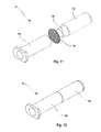
- Figs 11 and 12 show a second embodiment of a ventilation tube, which could form part of a window according to the invention, including the window described above and shown in the previous figures.
- the present ventilation tube 10 could be applied as a replacement or supplement to the ventilation tube 10 of the embodiment of Figs 1 to 10 .
- the ventilation tube 10 of Figs 11 and 12 comprises two tube parts 10a, 10b.
- an insect filter or net in the form of a flexible web or cloth 15 is positioned between the tube parts 10a, 10b.
- the web or cloth 15 has been cut out from an infinite web and need not be circular.
- a tube protrusion 10c of the tube part 10b is inserted into the tube part 10a such as to hold the web or cloth 15 stretched out within the ventilation tube 10 to form a filter or net suitable for keeping out insects.
- the web or cloth 15 is not visible in the assembled ventilation tube 10 as shown in Fig. 12 .
- the dimensions of the tube parts 10a, 10b could advantageously be adapted such as to position the insect filter at one end of the ventilation tube 10.
- the insect net of the ventilation tube according to the invention need not be positioned normal to axis of the ventilation tube; a more obliquely provided insect net could provide for a larger filter area.
- the necessary mesh size of the insect net might be made smaller with the same flow through the ventilation tube.
- more than one insect filter may be provided in one ventilation tube, e.g. one insect filter at each end. Hereby, both ends of the ventilation tube could be positioned towards the outside.
Landscapes
- Engineering & Computer Science (AREA)
- Civil Engineering (AREA)
- Structural Engineering (AREA)
- Architecture (AREA)
- Building Environments (AREA)
- Percussion Or Vibration Massage (AREA)
- Specific Sealing Or Ventilating Devices For Doors And Windows (AREA)
- Catching Or Destruction (AREA)
Applications Claiming Priority (1)
| Application Number | Priority Date | Filing Date | Title |
|---|---|---|---|
| PCT/DK2007/050193 WO2009076953A1 (en) | 2007-12-19 | 2007-12-19 | A ventilation tube for a window and window with a ventilation tube |
Publications (2)
| Publication Number | Publication Date |
|---|---|
| EP2235312A1 EP2235312A1 (en) | 2010-10-06 |
| EP2235312B1 true EP2235312B1 (en) | 2011-10-05 |
Family
ID=39791071
Family Applications (1)
| Application Number | Title | Priority Date | Filing Date |
|---|---|---|---|
| EP07846453A Not-in-force EP2235312B1 (en) | 2007-12-19 | 2007-12-19 | Window with a ventilation tube |
Country Status (4)
| Country | Link |
|---|---|
| EP (1) | EP2235312B1 (da) |
| AT (1) | ATE527426T1 (da) |
| DK (1) | DK2235312T3 (da) |
| WO (1) | WO2009076953A1 (da) |
Cited By (1)
| Publication number | Priority date | Publication date | Assignee | Title |
|---|---|---|---|---|
| EP4279679A1 (en) * | 2022-05-18 | 2023-11-22 | FAKRO PP Sp. z o.o. | Window frame with air supply duct |
Families Citing this family (1)
| Publication number | Priority date | Publication date | Assignee | Title |
|---|---|---|---|---|
| DE102020204188B4 (de) * | 2020-03-31 | 2021-10-28 | Roto Frank Dachsystem-Technologie GmbH | Dachflächenfenster |
Family Cites Families (9)
| Publication number | Priority date | Publication date | Assignee | Title |
|---|---|---|---|---|
| US3011422A (en) * | 1959-07-02 | 1961-12-05 | Frank J Scallon | Ventilating device |
| CH385464A (de) * | 1960-07-23 | 1964-12-15 | Klaus Esser Bau U Industriebed | Aus zwei ineinandergesetzten Schalenkörpern bestehende Lichtkuppel |
| US3307303A (en) * | 1964-01-13 | 1967-03-07 | Dan E Bloxsom | Fireproof skylight assembly |
| GB2183327B (en) * | 1984-08-25 | 1988-03-02 | Glidevale Building Prod | Wall ventilator and cavity wall ventilation system |
| US4825608A (en) * | 1987-03-23 | 1989-05-02 | Makin Brent A | Flush mounted self-flashing dual pane skylight |
| GB2318864A (en) * | 1996-11-02 | 1998-05-06 | Prod Design & Innovation Ltd | Ventilation device |
| GB9821933D0 (en) * | 1998-10-09 | 1998-12-02 | Top Frame Ltd | Ventilator |
| WO2004070155A1 (en) * | 2003-02-07 | 2004-08-19 | Jane Cynthia Margaret Harding | Window vent |
| AT502747B1 (de) * | 2005-10-31 | 2010-10-15 | Fuchs Dietrich Anton | Fensterflügel mit einstellbarer durchlüftung |
-
2007
- 2007-12-19 DK DK07846453.4T patent/DK2235312T3/da active
- 2007-12-19 EP EP07846453A patent/EP2235312B1/en not_active Not-in-force
- 2007-12-19 WO PCT/DK2007/050193 patent/WO2009076953A1/en not_active Ceased
- 2007-12-19 AT AT07846453T patent/ATE527426T1/de not_active IP Right Cessation
Cited By (1)
| Publication number | Priority date | Publication date | Assignee | Title |
|---|---|---|---|---|
| EP4279679A1 (en) * | 2022-05-18 | 2023-11-22 | FAKRO PP Sp. z o.o. | Window frame with air supply duct |
Also Published As
| Publication number | Publication date |
|---|---|
| DK2235312T3 (da) | 2012-01-23 |
| EP2235312A1 (en) | 2010-10-06 |
| WO2009076953A1 (en) | 2009-06-25 |
| ATE527426T1 (de) | 2011-10-15 |
Similar Documents
| Publication | Publication Date | Title |
|---|---|---|
| CA2136314C (en) | A sealing arrangement for windows, in particular roof windows | |
| US4776141A (en) | Skylights | |
| CA2292150C (en) | Method and apparatus for using a detent arrangement on a roof window frame and sash | |
| EP3396100A1 (en) | Flat roof window with external screen | |
| CA2768824C (en) | Seamless deck-sealing surround for skylights and roof windows | |
| JPS63142144A (ja) | 絶縁ガラス天窓組立体 | |
| SK47596A3 (en) | Roof ventilation device | |
| DK180873B1 (en) | A roof window, and a method of assembling such a roof window | |
| US10087635B2 (en) | Curb-mounted skylight | |
| US9316000B2 (en) | Method of replacing a previously-installed daylighting panel | |
| RU2621246C2 (ru) | Окно, имеющее сменное средство сопряжения, и способ его изготовления | |
| CN111075311B (zh) | 无钉无胶天窗及其制造方法 | |
| US20050000173A1 (en) | Skylight with sealing gasket | |
| US20070289226A1 (en) | Window backdam assembly for preventing water intrusion | |
| EP2235312B1 (en) | Window with a ventilation tube | |
| AU726665B2 (en) | Gable end roof ventilator | |
| WO1993025779A9 (en) | Ventilated ridge of a sloping glazed roof | |
| US11242709B1 (en) | Drainage system for a window and the like | |
| WO1994013921A1 (en) | A sealing arrangement for a glass-carrying window frame | |
| EP1533440A2 (en) | Sealing sash frame and roof window equipped therewith | |
| US20250320772A1 (en) | Top drainage system for windows and/or doors | |
| EP4136962B1 (en) | A greenhouse | |
| CN218379656U (zh) | 窗式空调器组件 | |
| JP3744398B2 (ja) | 等圧排水ジョイント | |
| KR20250082632A (ko) | 창틀용 배수구멍 차단기구 |
Legal Events
| Date | Code | Title | Description |
|---|---|---|---|
| PUAI | Public reference made under article 153(3) epc to a published international application that has entered the european phase |
Free format text: ORIGINAL CODE: 0009012 |
|
| 17P | Request for examination filed |
Effective date: 20100713 |
|
| AK | Designated contracting states |
Kind code of ref document: A1 Designated state(s): AT BE BG CH CY CZ DE DK EE ES FI FR GB GR HU IE IS IT LI LT LU LV MC MT NL PL PT RO SE SI SK TR |
|
| AX | Request for extension of the european patent |
Extension state: AL BA HR MK RS |
|
| 17Q | First examination report despatched |
Effective date: 20101119 |
|
| GRAP | Despatch of communication of intention to grant a patent |
Free format text: ORIGINAL CODE: EPIDOSNIGR1 |
|
| GRAC | Information related to communication of intention to grant a patent modified |
Free format text: ORIGINAL CODE: EPIDOSCIGR1 |
|
| GRAJ | Information related to disapproval of communication of intention to grant by the applicant or resumption of examination proceedings by the epo deleted |
Free format text: ORIGINAL CODE: EPIDOSDIGR1 |
|
| GRAP | Despatch of communication of intention to grant a patent |
Free format text: ORIGINAL CODE: EPIDOSNIGR1 |
|
| RTI1 | Title (correction) |
Free format text: WINDOW WITH A VENTILATION TUBE |
|
| DAX | Request for extension of the european patent (deleted) | ||
| GRAS | Grant fee paid |
Free format text: ORIGINAL CODE: EPIDOSNIGR3 |
|
| GRAA | (expected) grant |
Free format text: ORIGINAL CODE: 0009210 |
|
| AK | Designated contracting states |
Kind code of ref document: B1 Designated state(s): AT BE BG CH CY CZ DE DK EE ES FI FR GB GR HU IE IS IT LI LT LU LV MC MT NL PL PT RO SE SI SK TR |
|
| REG | Reference to a national code |
Ref country code: GB Ref legal event code: FG4D |
|
| REG | Reference to a national code |
Ref country code: CH Ref legal event code: EP |
|
| REG | Reference to a national code |
Ref country code: IE Ref legal event code: FG4D |
|
| REG | Reference to a national code |
Ref country code: DE Ref legal event code: R096 Ref document number: 602007017680 Country of ref document: DE Effective date: 20111208 |
|
| REG | Reference to a national code |
Ref country code: NL Ref legal event code: T3 |
|
| REG | Reference to a national code |
Ref country code: DK Ref legal event code: T3 |
|
| PG25 | Lapsed in a contracting state [announced via postgrant information from national office to epo] |
Ref country code: SI Free format text: LAPSE BECAUSE OF FAILURE TO SUBMIT A TRANSLATION OF THE DESCRIPTION OR TO PAY THE FEE WITHIN THE PRESCRIBED TIME-LIMIT Effective date: 20111005 |
|
| LTIE | Lt: invalidation of european patent or patent extension |
Effective date: 20111005 |
|
| REG | Reference to a national code |
Ref country code: AT Ref legal event code: MK05 Ref document number: 527426 Country of ref document: AT Kind code of ref document: T Effective date: 20111005 |
|
| PG25 | Lapsed in a contracting state [announced via postgrant information from national office to epo] |
Ref country code: LT Free format text: LAPSE BECAUSE OF FAILURE TO SUBMIT A TRANSLATION OF THE DESCRIPTION OR TO PAY THE FEE WITHIN THE PRESCRIBED TIME-LIMIT Effective date: 20111005 Ref country code: IS Free format text: LAPSE BECAUSE OF FAILURE TO SUBMIT A TRANSLATION OF THE DESCRIPTION OR TO PAY THE FEE WITHIN THE PRESCRIBED TIME-LIMIT Effective date: 20120205 Ref country code: BE Free format text: LAPSE BECAUSE OF FAILURE TO SUBMIT A TRANSLATION OF THE DESCRIPTION OR TO PAY THE FEE WITHIN THE PRESCRIBED TIME-LIMIT Effective date: 20111005 |
|
| PG25 | Lapsed in a contracting state [announced via postgrant information from national office to epo] |
Ref country code: PT Free format text: LAPSE BECAUSE OF FAILURE TO SUBMIT A TRANSLATION OF THE DESCRIPTION OR TO PAY THE FEE WITHIN THE PRESCRIBED TIME-LIMIT Effective date: 20120206 Ref country code: SE Free format text: LAPSE BECAUSE OF FAILURE TO SUBMIT A TRANSLATION OF THE DESCRIPTION OR TO PAY THE FEE WITHIN THE PRESCRIBED TIME-LIMIT Effective date: 20111005 Ref country code: GR Free format text: LAPSE BECAUSE OF FAILURE TO SUBMIT A TRANSLATION OF THE DESCRIPTION OR TO PAY THE FEE WITHIN THE PRESCRIBED TIME-LIMIT Effective date: 20120106 Ref country code: LV Free format text: LAPSE BECAUSE OF FAILURE TO SUBMIT A TRANSLATION OF THE DESCRIPTION OR TO PAY THE FEE WITHIN THE PRESCRIBED TIME-LIMIT Effective date: 20111005 |
|
| PG25 | Lapsed in a contracting state [announced via postgrant information from national office to epo] |
Ref country code: CY Free format text: LAPSE BECAUSE OF FAILURE TO SUBMIT A TRANSLATION OF THE DESCRIPTION OR TO PAY THE FEE WITHIN THE PRESCRIBED TIME-LIMIT Effective date: 20111005 |
|
| PG25 | Lapsed in a contracting state [announced via postgrant information from national office to epo] |
Ref country code: SK Free format text: LAPSE BECAUSE OF FAILURE TO SUBMIT A TRANSLATION OF THE DESCRIPTION OR TO PAY THE FEE WITHIN THE PRESCRIBED TIME-LIMIT Effective date: 20111005 Ref country code: BG Free format text: LAPSE BECAUSE OF FAILURE TO SUBMIT A TRANSLATION OF THE DESCRIPTION OR TO PAY THE FEE WITHIN THE PRESCRIBED TIME-LIMIT Effective date: 20120105 Ref country code: MC Free format text: LAPSE BECAUSE OF NON-PAYMENT OF DUE FEES Effective date: 20111231 Ref country code: EE Free format text: LAPSE BECAUSE OF FAILURE TO SUBMIT A TRANSLATION OF THE DESCRIPTION OR TO PAY THE FEE WITHIN THE PRESCRIBED TIME-LIMIT Effective date: 20111005 Ref country code: CZ Free format text: LAPSE BECAUSE OF FAILURE TO SUBMIT A TRANSLATION OF THE DESCRIPTION OR TO PAY THE FEE WITHIN THE PRESCRIBED TIME-LIMIT Effective date: 20111005 |
|
| REG | Reference to a national code |
Ref country code: CH Ref legal event code: PL |
|
| PLBE | No opposition filed within time limit |
Free format text: ORIGINAL CODE: 0009261 |
|
| STAA | Information on the status of an ep patent application or granted ep patent |
Free format text: STATUS: NO OPPOSITION FILED WITHIN TIME LIMIT |
|
| PG25 | Lapsed in a contracting state [announced via postgrant information from national office to epo] |
Ref country code: IT Free format text: LAPSE BECAUSE OF FAILURE TO SUBMIT A TRANSLATION OF THE DESCRIPTION OR TO PAY THE FEE WITHIN THE PRESCRIBED TIME-LIMIT Effective date: 20111005 Ref country code: RO Free format text: LAPSE BECAUSE OF FAILURE TO SUBMIT A TRANSLATION OF THE DESCRIPTION OR TO PAY THE FEE WITHIN THE PRESCRIBED TIME-LIMIT Effective date: 20111005 Ref country code: PL Free format text: LAPSE BECAUSE OF FAILURE TO SUBMIT A TRANSLATION OF THE DESCRIPTION OR TO PAY THE FEE WITHIN THE PRESCRIBED TIME-LIMIT Effective date: 20111005 |
|
| 26N | No opposition filed |
Effective date: 20120706 |
|
| REG | Reference to a national code |
Ref country code: IE Ref legal event code: MM4A |
|
| PG25 | Lapsed in a contracting state [announced via postgrant information from national office to epo] |
Ref country code: LI Free format text: LAPSE BECAUSE OF NON-PAYMENT OF DUE FEES Effective date: 20111231 Ref country code: CH Free format text: LAPSE BECAUSE OF NON-PAYMENT OF DUE FEES Effective date: 20111231 Ref country code: IE Free format text: LAPSE BECAUSE OF NON-PAYMENT OF DUE FEES Effective date: 20111219 |
|
| REG | Reference to a national code |
Ref country code: DE Ref legal event code: R097 Ref document number: 602007017680 Country of ref document: DE Effective date: 20120706 |
|
| PG25 | Lapsed in a contracting state [announced via postgrant information from national office to epo] |
Ref country code: AT Free format text: LAPSE BECAUSE OF FAILURE TO SUBMIT A TRANSLATION OF THE DESCRIPTION OR TO PAY THE FEE WITHIN THE PRESCRIBED TIME-LIMIT Effective date: 20111005 |
|
| PG25 | Lapsed in a contracting state [announced via postgrant information from national office to epo] |
Ref country code: MT Free format text: LAPSE BECAUSE OF FAILURE TO SUBMIT A TRANSLATION OF THE DESCRIPTION OR TO PAY THE FEE WITHIN THE PRESCRIBED TIME-LIMIT Effective date: 20111005 |
|
| PG25 | Lapsed in a contracting state [announced via postgrant information from national office to epo] |
Ref country code: ES Free format text: LAPSE BECAUSE OF FAILURE TO SUBMIT A TRANSLATION OF THE DESCRIPTION OR TO PAY THE FEE WITHIN THE PRESCRIBED TIME-LIMIT Effective date: 20120116 |
|
| PG25 | Lapsed in a contracting state [announced via postgrant information from national office to epo] |
Ref country code: LU Free format text: LAPSE BECAUSE OF NON-PAYMENT OF DUE FEES Effective date: 20111219 |
|
| PG25 | Lapsed in a contracting state [announced via postgrant information from national office to epo] |
Ref country code: FI Free format text: LAPSE BECAUSE OF FAILURE TO SUBMIT A TRANSLATION OF THE DESCRIPTION OR TO PAY THE FEE WITHIN THE PRESCRIBED TIME-LIMIT Effective date: 20111005 |
|
| PG25 | Lapsed in a contracting state [announced via postgrant information from national office to epo] |
Ref country code: TR Free format text: LAPSE BECAUSE OF FAILURE TO SUBMIT A TRANSLATION OF THE DESCRIPTION OR TO PAY THE FEE WITHIN THE PRESCRIBED TIME-LIMIT Effective date: 20111005 |
|
| PG25 | Lapsed in a contracting state [announced via postgrant information from national office to epo] |
Ref country code: HU Free format text: LAPSE BECAUSE OF FAILURE TO SUBMIT A TRANSLATION OF THE DESCRIPTION OR TO PAY THE FEE WITHIN THE PRESCRIBED TIME-LIMIT Effective date: 20111005 |
|
| REG | Reference to a national code |
Ref country code: FR Ref legal event code: PLFP Year of fee payment: 9 |
|
| REG | Reference to a national code |
Ref country code: FR Ref legal event code: PLFP Year of fee payment: 10 |
|
| REG | Reference to a national code |
Ref country code: FR Ref legal event code: PLFP Year of fee payment: 11 |
|
| PGFP | Annual fee paid to national office [announced via postgrant information from national office to epo] |
Ref country code: NL Payment date: 20171213 Year of fee payment: 11 Ref country code: DK Payment date: 20171212 Year of fee payment: 11 Ref country code: FR Payment date: 20171127 Year of fee payment: 11 |
|
| PGFP | Annual fee paid to national office [announced via postgrant information from national office to epo] |
Ref country code: GB Payment date: 20171213 Year of fee payment: 11 |
|
| REG | Reference to a national code |
Ref country code: DK Ref legal event code: EBP Effective date: 20181231 |
|
| REG | Reference to a national code |
Ref country code: NL Ref legal event code: MM Effective date: 20190101 |
|
| GBPC | Gb: european patent ceased through non-payment of renewal fee |
Effective date: 20181219 |
|
| PG25 | Lapsed in a contracting state [announced via postgrant information from national office to epo] |
Ref country code: NL Free format text: LAPSE BECAUSE OF NON-PAYMENT OF DUE FEES Effective date: 20190101 |
|
| PG25 | Lapsed in a contracting state [announced via postgrant information from national office to epo] |
Ref country code: FR Free format text: LAPSE BECAUSE OF NON-PAYMENT OF DUE FEES Effective date: 20181231 |
|
| PG25 | Lapsed in a contracting state [announced via postgrant information from national office to epo] |
Ref country code: GB Free format text: LAPSE BECAUSE OF NON-PAYMENT OF DUE FEES Effective date: 20181219 |
|
| PG25 | Lapsed in a contracting state [announced via postgrant information from national office to epo] |
Ref country code: DK Free format text: LAPSE BECAUSE OF NON-PAYMENT OF DUE FEES Effective date: 20181231 |
|
| PGFP | Annual fee paid to national office [announced via postgrant information from national office to epo] |
Ref country code: DE Payment date: 20201208 Year of fee payment: 14 |
|
| REG | Reference to a national code |
Ref country code: DE Ref legal event code: R119 Ref document number: 602007017680 Country of ref document: DE |
|
| PG25 | Lapsed in a contracting state [announced via postgrant information from national office to epo] |
Ref country code: DE Free format text: LAPSE BECAUSE OF NON-PAYMENT OF DUE FEES Effective date: 20220701 |