EP2234233B1 - Suspension clamp - Google Patents
Suspension clamp Download PDFInfo
- Publication number
- EP2234233B1 EP2234233B1 EP09290222A EP09290222A EP2234233B1 EP 2234233 B1 EP2234233 B1 EP 2234233B1 EP 09290222 A EP09290222 A EP 09290222A EP 09290222 A EP09290222 A EP 09290222A EP 2234233 B1 EP2234233 B1 EP 2234233B1
- Authority
- EP
- European Patent Office
- Prior art keywords
- suspension clamp
- shunt
- power line
- overhead power
- bolt
- Prior art date
- Legal status (The legal status is an assumption and is not a legal conclusion. Google has not performed a legal analysis and makes no representation as to the accuracy of the status listed.)
- Active
Links
Images


Classifications
-
- H—ELECTRICITY
- H02—GENERATION; CONVERSION OR DISTRIBUTION OF ELECTRIC POWER
- H02G—INSTALLATION OF ELECTRIC CABLES OR LINES, OR OF COMBINED OPTICAL AND ELECTRIC CABLES OR LINES
- H02G7/00—Overhead installations of electric lines or cables
- H02G7/05—Suspension arrangements or devices for electric cables or lines
- H02G7/053—Suspension clamps and clips for electric overhead lines not suspended to a supporting wire
Definitions
- the invention relates to a suspension clamp according to claim 1.
- suspension clamps for supporting the conductor of an overhead power line.
- the clamp is attached to a mast via an insulator string.
- Such suspension clamps are for example known from the US 7,368,660 B2 , the WO 2007/126349 A1 , the WO 9734354 A1 , the FR 2430116 A , the US 1,871,336 A , the US 1,871,336 A and the US 1,776,531 A .
- US 2,868,865 A teaches to provide a suspension clamp with a shunt member for providing a good electrical connection between a body of the clamp and a supporting portion of the clamp.
- the suspension clamp for suspending an overhead power line comprises a body with a contact surface and at least one locking system with a locking surface.
- the contact surface and the locking surface are designed for clamping the overhead power line.
- the suspension clamp further comprises a shunt with an electrically conductive surface, wherein the conductive surface is designed for electrically contacting the overhead power line.
- the contact surface and the locking surface comprise a lower electrical conductivity than the conductive surface of the shunt.
- this suspension clamp It is an advantage of this suspension clamp that the mechanical and the electrical functions of the suspension clamp are separated.
- the mechanical slipping control is ensured by the contact surface and the locking surface.
- the electrical function of the suspension clamp is ensured by the shunt which can be made of a highly conductive material.
- the contact surface and the locking surface are coated with a coating material.
- the coating material comprises a lower electrical conductivity than the material of the conductive surface of the shunt.
- the mechanical slipping control is then supported by the coating which may have a lower friction coefficient than a highly conductive one.
- a further advantage is that the coating allows for repeating the slipping operation several times while keeping the slipping force values constant and avoiding a damage of the overhead power line.
- the coating material comprises molybdenum.
- molybdenum has a low friction coefficient.
- the shunt comprises copper.
- copper is highly electrically conductive.
- the shunt comprises the shape of a roller, wherein the conductive surface forms the tread of the roller.
- the shunt approximately comprises the profile of an isosceles trapezoid, wherein the conductive surface is arranged along the longer of the two parallel sides of the trapezoid.
- a central area of the contact surface comprises a recess, wherein the conductive surface is arranged in the recess of the contact surface, wherein the contact surface and the conductive surface together form a supporting area for the overhead power line.
- the conductive surface of the shunt protrudes from the contact surface of the body.
- this ensures a good electrical contact between the overhead power line and the conductive surface of the shunt.
- a first and a second locking system are provided, wherein the locking surfaces of the first and the second locking systems are opposed to the contact surface, wherein the locking surface of the first locking system, the conductive surface of the shunt and the locking surface of the second locking system are arranged consecutively in the running direction of the overhead power line.
- the body comprises an essentially U-shaped profile formed by two upper arms, wherein the contact surface is arranged in a groove formed between the two upper arms.
- a lower ridge is attached to the closed side of the U-shaped body, wherein a central area of the lower ridge in the running direction of the overhead power line comprises a recess.
- the shunt is arranged in the recess of the lower ridge.
- suspension clamp further comprises at least one strap that extends approximately perpendicular to the running direction of the overhead power line.
- the shunt, the strap and the body are connected by a first bolt.
- the first bolt and the strap are electrically conductive.
- the first bolt provides an electrical connection between the shunt and the strap.
- this allows an occasional short-circuit current to flow-out via the strap.
- the body and the strap are independently pivotable around the first bolt.
- this allows for slight movements of the overhead power line, for example in the case of wind.
- At least one insulating bearing is provided between the first bolt and the body.
- the insulating bearing electrically isolates the body from the first bolt.
- the suspension clamp comprises two straps which are connected by a second bolt.
- the second bolt is electrically connected to the two straps.
- this allows to attach the suspension clamp to a mast via the second bolt.
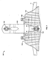
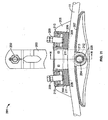
- FIG. 1 shows a front view of a suspension clamp 101 according to a first embodiment.
- the suspension clamp 101 is designed for suspending an overhead power line 11.
- the overhead power line 11 is an electrically conductive conductor that can be used for transmitting electrical power.
- the overhead power line 11 may for example be a stranded conductor comprising a plurality of metallic wires.
- the overhead power line 11 may for example comprise aluminum.
- the suspension clamp 101 is designed for being attached to a mast.
- the suspension clamp 101 comprises a body 105 for supporting the overhead power line 11.
- the suspension clamp 101 comprises a first beam-like strap 103 that extends from the body 105 in a direction approximately perpendicular to the running direction of the overhead power line 11.
- a second strap 103 is arranged behind the first strap 103, not visible in figure 1 .
- the straps 103 are connected to the body 105 with a first bolt 104.
- the first bolt 104 extends trough the straps 103 near one end of the beam-like straps 103.
- the first strap 103 and the second strap 103 are connected to each other with a second bolt 102 that extends trough the straps 103 near a second end of the beam-like straps 103.
- the suspension clamp 101 further comprises two locking systems 106.
- the two locking systems 106 are connected to the body 105.
- the two locking systems 106 are arranged consecutively in the running direction of the overhead power line 11.
- the body 105 can be made of a conductive or a non-conductive material. Preferably the body 105 is made of a metal.
- the straps 103 are made of a conductive material, for example a metal.
- the first bolt 104 and the second bolt 102 are made of an electrically conductive material, for example a metal.
- Figure 2 shows a sliced view of the suspension clamp 101.
- the body 105 comprises a contact surface 107 that supports the overhead power line 11.
- the contact surface 107 is slightly curved in the running direction of the overhead power line 11.
- the curvature of the contact surface 107 is such that the weight of the overhead power line 11 provides contact between the overhead power line 11 and the contact surface 107 over a large segment of the contact surface 107 in the running direction of the overhead power line 11.
- the contact surface 107 of the body 105 is coated with a material with a low friction coefficient.
- the friction coefficient may for example be in the order 0.1.
- the coating may be electrically insulating or comprise a low electric conductivity.
- the electric conductivity may for example be such that the resistance between the body 105 and the overhead power line 11 is about 1 Ohm.
- the coating on the contact surface 107 may for example comprise molybdenum.
- the coating may also comprise a polymeric basis.
- the coating may for example comprise a molybdenum disulfide basis with auditioned resin on epoxy basis which bonds to the contact surface 107.
- the coating may be assimilated to a varnish.
- the coating material may be pure molybdenum.
- Each of the two locking systems 106 comprises a locking surface 108 that is in contact with the overhead power line 11.
- Each locking surface 108 is opposed to the contact surface 107 of the body 105.
- the locking surfaces 108 are also coated with a coating material, preferably with the same material as the coating of the contact surface 107.
- the locking surfaces 108 and the contact surface 107 are designed for clamping the overhead power line 11 between the contact surface 107 and the locking surfaces 108.
- the contact surface 107 comprises a recess in the central area of the contact surface 107.
- the recess in the contact surface 107 is arranged between the two locking systems 106 in the running direction of the overhead power line 11.
- a conductive surface 113 of a shunt 112 is arranged in the recess of the contact surface 107.
- the conductive surface 113 is arranged approximately coplanar with the contact surface 107 but protrudes slightly from the contact surface 107.
- the conductive surface 113 of the shunt 112 is electrically conductive.
- the material of the conductive surface 112 preferentially comprises a higher electric conductivity than the coating material on the contact surface 107 of the body 105.
- the shunt 112 and the conductive surface 113 of the shunt 112 may for example comprise copper or be made of pure copper.
- the shunt 112 will be explained in greater detail with references to figures 7 and 8 below.
- Each locking system 106 comprises a fixation body 111, a fixation plate 110 and a fixation bolt 109.
- the locking surface 108 is arranged on the fixation body 111.
- the locking systems 106 will be explained in greater detail with references to figures 5 , 9 and 10 below.
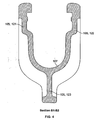
- Figure 3 shows a vertical section through the body 105 along the line A1A2 shown in figure 2 .
- Figure 4 shows a vertical section through the body 105 along the line B1B2 shown in figure 2 .
- Figures 3 and 4 show that an upper part of the body 105 approximately comprises a U-shape with a first upper arm 121 and a second upper arm 122.
- the contact surface 107 is arranged between the first upper arm 121 and the second upper arm 122 and forms the lower surface of the U-shaped part of the body 105.
- the contact surface 107 is concave. This is advantageous as it increases the contact area between the contact surface 107 and the essentially cylindrical overhead power line 11.
- the body 105 Attached to the closed side of the U-shaped body 105 the body 105 comprises a lower ridge 123.
- the body 105 approximately comprises the shape of the letter Y.
- the lower ridge 123 is widened and comprises a recess 124.
- the contact surface 107 comprises an opening.
- the recess 124 is provided for housing the shunt 112.
- the lower ridge 124 furthermore comprises a first bore 125 that extends perpendicular to the running direction of the running direction of the overhead power line 11 through the body 105.
- the first bore 125 is provided for housing the first bolt 104.
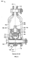
- Figure 5 shows another sectional drawing of the suspension clamp 101 along the line B1A2 shown in figure 2 .
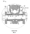
- Figure 6 shows a magnified drawing of a central part of figure 5.
- Figure 5 shows the two straps 103. Near a first end of the two steps 103 the two straps 103 are connected with the first bolt 104. Near the second end of the straps 103 the straps 103 are connected with the second bolt 102. The first bolt 104 and the second bolt 102 are electrically coupled via the straps 103.
- the body 105 is arranged between the two straps 103.
- the shunt 112 is arranged in the recess 124 of the body 105.
- the overhead power line 11 is supported by the contact surface 107 of the body 105 and the conductive surface 113 of the shunt 112.
- One of the two locking systems 106 is shown between the first upper arm 121 and the second upper arm 122 of the body 105.
- the locking surface 108 of the fixation body 111 of the locking system 106 is in contact with the overhead power line 11 and presses the overhead power line 11 against the conductive surface 113 of the shunt 112 and the contact surface 107 of the body 105.
- a contact pressure between the locking surface 108 and the overhead power line 11 is created by the fixation plate 110 and the fixation bolt 109 of the locking system 106.
- the fixation plate 111 rests against a flange of the body 105.
- the fixation bolt 109 extends through the fixation plate 110 and presses the fixation body 111 and the fixation plate 110 apart from each other, pressing the fixation body 111 with the locking surface 108 against the overhead power line 11.
- the fixation bolt 109 allows for regulating the contact pressure between the locking surface 108 and the overhead power line 11.
- the shunt 112 Arranged in the recess 124 in the lower ridge 123 of the body 105 is the shunt 112 with the conductive surface 113 that is in contact with the overhead power line 11.
- the shunt 112 comprises a second bore 126.
- the first bolt 104 extends through the first strap 103, the first bore 125 in the body 105, the second bore 126 in the shunt 112 and the second strap 103.
- the shunt 112 is in electrical contact with the first bolt 104 in a contact area 114 on the inner wall of the second bore 126. Since the overhead power line 11 is in electrical contact with the shunt 112 at the conductive surface 113 of the shunt 112, the shunt 112 provides an electrical connection between the overhead power line 11 and the first bolt 104. Since the first bolt 104 is in electrical connection with the straps 103 and the straps 103 are in electrical connection with the second bolt 102, there is an electrical connection between the overhead power line 11 and the second bolt 102.
- the bearings 115 Arranged in the first bore 125 in the body 105 are two bearings 115 surrounding the first bolt 104.
- the bearings 115 electrically isolate the body 105 from the first bolt 104.
- the bearings 115 may therefore be made out of an insulating material.
- the size of the recess 124 in the body 105 and the size of the shunt 112 are such that a small gap is created between the shunt 112 and the body 105.
- the length of the bearing 115 is such that the shunt 112 cannot move in the axial direction of the first bolt 104, therefore maintaining the gap between the shunt 112 and the body 105.
- This gap electrically isolates the shunt 112 from the body 105. Consequently the body 105 is electrically isolated from the overhead power line 11, the shunt 112, the first bolt 104 and the straps 103.
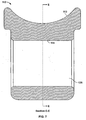
- Figure 7 shows a sectional view of the shunt 112 along a line CC shown in figure 5 .
- the shunt 112 comprises an approximately rectangular profile.
- An upper end of the shunt 112 comprises the conductive surface 113.
- the conductive surface 113 is concave. This is advantageous, as it increases the contact area between the conductive surface 113 and the approximately cylindrical overhead power line 11.
- a lower end of the shunt 112 comprises the second bore 126.
- An inner wall of the second boar 126 constitutes the contact area 114.
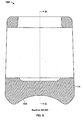
- Figure 8 shows another sectional view of the shunt 112 along a line EE shown in figure 7 .
- the shunt 112 comprises approximately a profile of an isosceles trapezoid.
- the contact surface 113 is arranged along the longer of the two parallel sites of the trapezoid.
- Figure 9 shows a sectional view of the fixation body 111 of the locking system 106 along the line 81B2 shown in figure 2 .
- the fixation body 111 comprises the locking surface 108.
- the locking surface 108 is concave, which is advantageous, as it increases the contact area between the locking surface 108 and the approximately cylindrical overhead power line 11.
- Figure 10 shows a sectional view of the fixation body 111 of the locking system 106 along a line GG shown in figure 9 .
- the fixation body 111 comprises an approximately rectangular shape.
- An upper part of the fixation body 111 comprises an opening that is provided for receiving the fixation bolt 109.
- Figure 11 shows a sectional view of a suspension clamp 201 according to a second embodiment of the invention.
- the suspension clamp 201 comprises a body 205 with a contact surface 207 that is coated with a material with a low friction coefficient, for example molybdenum.
- the body 205 and the contact surface 207 are identical to the body 105 and the contact surface 107.
- the coating material may be the same as described in conjunction with the contact surface 107 of the suspension clamp 101 according to the first embodiment.
- the suspension clamp 201 further comprises two straps 203 that are connected to the body 205 with a first bolt 204 and that are connected to each other with a second bolt 202.
- the straps 203, the first bolt 204 and the second bolt 202 are identical to the straps 103, the first bolt 104 and the second bolt 102 of the suspension clamp 101 of figure 2 .
- the suspension clamp 201 further comprises two locking systems 206 that are identical to the locking systems 106 of the suspension clamp 101.
- Each locking system 206 comprises a fixation body 211, a fixation plate 210 and a fixation bolt 209.
- Each fixation body 211 comprises a locking surface 208 that is coated with a material with a low friction coefficient, for example molybdenum.
- the coating material may be the same material as the coating material on the contact surface 207.
- the suspension clamp 201 of the second embodiment shown in figure 11 further comprises a shunt 212 that is arranged in a recess of the body 205.
- the shunt 212 of the suspension clamp 201 comprises the shape of a roller.
- the shunt 212 comprises a second bore 226 that is provided for receiving the first bolt 204.
- An inner wall of the second boar 226 constitutes a contact area 214 that provides an electrical contact between the shunt 212 and the first bolt 204.
- the shunt 212 further comprises a conductive surface 213 that is formed by the tread of the roller-shaped shunt 212.
- the conductive surface 213 is in contact with the overhead power line 11 and provides an electrical connection between the overhead power line 11 and the shunt 212.
- the shunt 212 is made of an electrically conductive material.
- the shunt 212 may for example comprise copper.
- Figure 12 shows a detail of a sectional view of the suspension clamp 201 along a line HH shown in figure 11 .
- Figure 12 shows that the conductive surface 213 of the shunt 212 is concave, which is advantageous, as it increases the contact area between the conductive surface 213 and the essentially cylindrical overhead power line 11.
- the suspension clamp 201 further comprises two bearings 215 that are provided between the first bolt 204 and the body 205 of the suspension clamp 201 to electrically isolate the first bolt 204 from the body 205.
- a small gap between the body 205 and the shunt 212 electrically isolates the body 205 from the shunt 212. This complies with the description of the suspension clamp 101 according to the first embodiment.
- the roller-shaped shunt 212 can rotate around the axis constituted by the first bolt 204. If the overhead power line 11 slips in an axial direction of the overhead power line 11 through the suspension clamp 201 the conductive surface 213 of the shunt 212 can roll along the surface of the overhead power line 11. This has the advantage that the conductive surface 213 of the shunt 212 is not damaged by abrasion in case the overhead power line 11 slips through the suspension clamp 201.
- the suspension clamps 101 and 201 are designed for suspending the overhead power line 11. In normal operation the suspension clamps 101, 201 should tightly retain the overhead power line 11, without allowing the overhead power line 11 to slip in an axial direction of the overhead power line 11 through the suspension clamps 101, 201. If, however, a force F is applied on the overhead power line 11 in an axial direction of the overhead power line 11 and that force F exceeds a predefined threshold value, the overhead power line 11 must be permitted to slip through the suspension clamps 101, 201. This may for example be the case if one mast of an overhead power line system has crashed.
- the overhead power line 11 may slip through the suspension claims 101, 201 while experiencing an approximately constant mechanical slipping force.
- neither the contact surfaces 107, 207, the locking surfaces 108, 208 or the wires of the stranded conductors of the overhead power line 11 should be damaged by the movement of the overhead power line 11. This is achieved by coating the contact surfaces 107, 207 and the locking surfaces 108, 208 with a material with a low friction coefficient, preferably with molybdenum.
- a further purpose of the suspension clamps 101 and 201 is to flow-out short circuit current between the overhead power line 11 and the suspension clamps 101, 201 in case of a flash-over occurring on the overhead power line transmission grid.
- this function is achieved by providing an electrical connection between the second bolt 102, 202 and the overhead power line 11 via the straps 103, 203, the first bolt 104, 204 and the shunt 112, 212.
- Figure 13 shows a graph depicting the force F applied to the overhead power line 11 in an axial direction of the overhead power line 11 that is necessary to slip the overhead power line 11 through the suspension clamp 101, 201 by a distance d.
- the force F applied to the overhead power line 11 needs to exceed a threshold value to start moving the overhead power line 11 through the suspension claims 101, 201.
- the suspension clamp 101, 201 applies an approximately constant mechanical slipping force on the overhead power line 11.
- the threshold value of the force F and the mechanical slipping force applied to the overhead power line 11 may be regulated with the fixation bolts 109, 209 of the locking systems 106, 206 of the suspension clamps 101, 202.
Landscapes
- Current-Collector Devices For Electrically Propelled Vehicles (AREA)
- Suspension Of Electric Lines Or Cables (AREA)
- Supporting Of Heads In Record-Carrier Devices (AREA)
- Body Structure For Vehicles (AREA)
- Electric Cable Installation (AREA)
Priority Applications (5)
| Application Number | Priority Date | Filing Date | Title |
|---|---|---|---|
| PL09290222T PL2234233T3 (pl) | 2009-03-26 | 2009-03-26 | Zacisk wieszakowy |
| ES09290222T ES2374698T3 (es) | 2009-03-26 | 2009-03-26 | Grifa de suspensión. |
| EP09290222A EP2234233B1 (en) | 2009-03-26 | 2009-03-26 | Suspension clamp |
| AT09290222T ATE533216T1 (de) | 2009-03-26 | 2009-03-26 | Aufhängungsklemme |
| HR20110986T HRP20110986T1 (hr) | 2009-03-26 | 2011-12-30 | Ovjesna stezaljka |
Applications Claiming Priority (1)
| Application Number | Priority Date | Filing Date | Title |
|---|---|---|---|
| EP09290222A EP2234233B1 (en) | 2009-03-26 | 2009-03-26 | Suspension clamp |
Publications (2)
| Publication Number | Publication Date |
|---|---|
| EP2234233A1 EP2234233A1 (en) | 2010-09-29 |
| EP2234233B1 true EP2234233B1 (en) | 2011-11-09 |
Family
ID=40933593
Family Applications (1)
| Application Number | Title | Priority Date | Filing Date |
|---|---|---|---|
| EP09290222A Active EP2234233B1 (en) | 2009-03-26 | 2009-03-26 | Suspension clamp |
Country Status (5)
| Country | Link |
|---|---|
| EP (1) | EP2234233B1 (pl) |
| AT (1) | ATE533216T1 (pl) |
| ES (1) | ES2374698T3 (pl) |
| HR (1) | HRP20110986T1 (pl) |
| PL (1) | PL2234233T3 (pl) |
Families Citing this family (5)
| Publication number | Priority date | Publication date | Assignee | Title |
|---|---|---|---|---|
| CN103606871B (zh) * | 2013-11-27 | 2017-01-25 | 国家电网公司 | 一种释放型悬垂线夹 |
| CN106207862B (zh) * | 2016-09-24 | 2017-11-07 | 国家电网公司 | 悬垂线夹回转轴带电复位器 |
| CN106410716B (zh) * | 2016-09-30 | 2017-11-28 | 国家电网公司 | 输电线路悬垂线夹装销器 |
| CN109524934B (zh) * | 2018-09-17 | 2020-07-07 | 国网浙江乐清市供电有限公司 | 一种绝缘子固定抗拉悬垂线夹 |
| CN114421398B (zh) * | 2022-01-24 | 2023-03-10 | 广东鑫源恒业电力线路器材有限公司 | 一种铜铝复合工艺生产的悬垂线夹 |
Family Cites Families (8)
| Publication number | Priority date | Publication date | Assignee | Title |
|---|---|---|---|---|
| US1776531A (en) | 1926-03-27 | 1930-09-23 | Woodruff William Warren | Suspension clamp |
| US1871360A (en) | 1930-10-15 | 1932-08-09 | George F Colley | Automatic spark retarder for automobiles |
| US1871336A (en) | 1931-08-13 | 1932-08-09 | Westinghouse Electric & Mfg Co | Cable support |
| US2868865A (en) * | 1955-08-08 | 1959-01-13 | Anderson Brass Works | Shunt for power line clamps |
| FR2430116A1 (fr) | 1978-06-29 | 1980-01-25 | Pelissier Yvan | Pince de suspension a glissement |
| FR2746223B1 (fr) | 1996-03-12 | 1998-05-29 | Pince a glissement controle pour la suspension d'un cable de garde ou d'un conducteur electrique | |
| WO2005117227A1 (en) | 2004-05-26 | 2005-12-08 | Claude Hardy | Anti-cascading suspension clamps for overhead power transmission lines |
| US9010695B2 (en) | 2006-04-28 | 2015-04-21 | Nkt Cables Group A/S | Cable suspension device |
-
2009
- 2009-03-26 EP EP09290222A patent/EP2234233B1/en active Active
- 2009-03-26 AT AT09290222T patent/ATE533216T1/de active
- 2009-03-26 ES ES09290222T patent/ES2374698T3/es active Active
- 2009-03-26 PL PL09290222T patent/PL2234233T3/pl unknown
-
2011
- 2011-12-30 HR HR20110986T patent/HRP20110986T1/hr unknown
Also Published As
| Publication number | Publication date |
|---|---|
| HRP20110986T1 (hr) | 2012-01-31 |
| ATE533216T1 (de) | 2011-11-15 |
| ES2374698T3 (es) | 2012-02-21 |
| PL2234233T3 (pl) | 2012-03-30 |
| EP2234233A1 (en) | 2010-09-29 |
Similar Documents
| Publication | Publication Date | Title |
|---|---|---|
| EP2234233B1 (en) | Suspension clamp | |
| US10355470B2 (en) | Cable fitting for connecting a high-voltage cable to a high-voltage component | |
| EP2783422B1 (en) | Electrical connector | |
| CN102918732B (zh) | 线路保护系统 | |
| US8932087B2 (en) | Hot line stirrup connector | |
| KR102398546B1 (ko) | 낙뢰피해방지형 가공배전선 고정기기 | |
| WO2007146022A2 (en) | Aerial cable spacer with cable retaining arm having non-rectangular cross section | |
| EP3258561B1 (en) | An insulator | |
| US10847280B2 (en) | Wire harness | |
| US8952565B2 (en) | Deflection containing electrical conductor | |
| WO2004008465A1 (en) | Combined suspension cable and electrical conductor | |
| US10218162B2 (en) | High voltage aerial cable spacer | |
| US5018825A (en) | Overhead optical transmission system | |
| US20100276172A1 (en) | Holding device for an overhead line and overhead line configuration | |
| KR102187767B1 (ko) | 배전선로의 접속 연결장치 | |
| EP2557636B1 (en) | Corona shield for high voltage connectors | |
| US8740657B2 (en) | Cable lug pad | |
| US8777678B2 (en) | Quick lock conductor receiver | |
| EP2871720B1 (en) | Preformed Plate for an Insulation-Piercing Connector | |
| US20170194071A9 (en) | Deflection containing electrical conductor | |
| US12548990B2 (en) | Electrical bus bar assembly | |
| JP4863674B2 (ja) | 電線の電波障害低減金具及び電線の電波障害低減方法 | |
| CN219937551U (zh) | 线夹及电缆引线架 | |
| IE42545B1 (en) | Improvements in and relating a spacer for linear bodies | |
| CA2813629C (en) | Hot line stirrup connector |
Legal Events
| Date | Code | Title | Description |
|---|---|---|---|
| PUAI | Public reference made under article 153(3) epc to a published international application that has entered the european phase |
Free format text: ORIGINAL CODE: 0009012 |
|
| AK | Designated contracting states |
Kind code of ref document: A1 Designated state(s): AT BE BG CH CY CZ DE DK EE ES FI FR GB GR HR HU IE IS IT LI LT LU LV MC MK MT NL NO PL PT RO SE SI SK TR |
|
| AX | Request for extension of the european patent |
Extension state: AL BA RS |
|
| 17P | Request for examination filed |
Effective date: 20101016 |
|
| 17Q | First examination report despatched |
Effective date: 20101116 |
|
| AKX | Designation fees paid |
Designated state(s): AT BE BG CH CY CZ DE DK EE ES FI FR GB GR HR HU IE IS IT LI LT LU LV MC MK MT NL NO PL PT RO SE SI SK TR |
|
| GRAP | Despatch of communication of intention to grant a patent |
Free format text: ORIGINAL CODE: EPIDOSNIGR1 |
|
| GRAS | Grant fee paid |
Free format text: ORIGINAL CODE: EPIDOSNIGR3 |
|
| GRAA | (expected) grant |
Free format text: ORIGINAL CODE: 0009210 |
|
| AK | Designated contracting states |
Kind code of ref document: B1 Designated state(s): AT BE BG CH CY CZ DE DK EE ES FI FR GB GR HR HU IE IS IT LI LT LU LV MC MK MT NL NO PL PT RO SE SI SK TR |
|
| REG | Reference to a national code |
Ref country code: GB Ref legal event code: FG4D |
|
| REG | Reference to a national code |
Ref country code: CH Ref legal event code: EP |
|
| REG | Reference to a national code |
Ref country code: IE Ref legal event code: FG4D |
|
| REG | Reference to a national code |
Ref country code: HR Ref legal event code: TUEP Ref document number: P20110986 Country of ref document: HR |
|
| REG | Reference to a national code |
Ref country code: DE Ref legal event code: R096 Ref document number: 602009003595 Country of ref document: DE Effective date: 20120119 |
|
| REG | Reference to a national code |
Ref country code: HR Ref legal event code: T1PR Ref document number: P20110986 Country of ref document: HR |
|
| REG | Reference to a national code |
Ref country code: ES Ref legal event code: FG2A Ref document number: 2374698 Country of ref document: ES Kind code of ref document: T3 Effective date: 20120221 |
|
| REG | Reference to a national code |
Ref country code: NL Ref legal event code: VDEP Effective date: 20111109 |
|
| REG | Reference to a national code |
Ref country code: PL Ref legal event code: T3 |
|
| LTIE | Lt: invalidation of european patent or patent extension |
Effective date: 20111109 |
|
| PG25 | Lapsed in a contracting state [announced via postgrant information from national office to epo] |
Ref country code: LT Free format text: LAPSE BECAUSE OF FAILURE TO SUBMIT A TRANSLATION OF THE DESCRIPTION OR TO PAY THE FEE WITHIN THE PRESCRIBED TIME-LIMIT Effective date: 20111109 Ref country code: IS Free format text: LAPSE BECAUSE OF FAILURE TO SUBMIT A TRANSLATION OF THE DESCRIPTION OR TO PAY THE FEE WITHIN THE PRESCRIBED TIME-LIMIT Effective date: 20120309 Ref country code: NO Free format text: LAPSE BECAUSE OF FAILURE TO SUBMIT A TRANSLATION OF THE DESCRIPTION OR TO PAY THE FEE WITHIN THE PRESCRIBED TIME-LIMIT Effective date: 20120209 |
|
| RAP2 | Party data changed (patent owner data changed or rights of a patent transferred) |
Owner name: TYCO ELECTRONICS SIMEL S.A.S |
|
| PG25 | Lapsed in a contracting state [announced via postgrant information from national office to epo] |
Ref country code: NL Free format text: LAPSE BECAUSE OF FAILURE TO SUBMIT A TRANSLATION OF THE DESCRIPTION OR TO PAY THE FEE WITHIN THE PRESCRIBED TIME-LIMIT Effective date: 20111109 Ref country code: PT Free format text: LAPSE BECAUSE OF FAILURE TO SUBMIT A TRANSLATION OF THE DESCRIPTION OR TO PAY THE FEE WITHIN THE PRESCRIBED TIME-LIMIT Effective date: 20120309 Ref country code: SE Free format text: LAPSE BECAUSE OF FAILURE TO SUBMIT A TRANSLATION OF THE DESCRIPTION OR TO PAY THE FEE WITHIN THE PRESCRIBED TIME-LIMIT Effective date: 20111109 Ref country code: GR Free format text: LAPSE BECAUSE OF FAILURE TO SUBMIT A TRANSLATION OF THE DESCRIPTION OR TO PAY THE FEE WITHIN THE PRESCRIBED TIME-LIMIT Effective date: 20120210 Ref country code: SI Free format text: LAPSE BECAUSE OF FAILURE TO SUBMIT A TRANSLATION OF THE DESCRIPTION OR TO PAY THE FEE WITHIN THE PRESCRIBED TIME-LIMIT Effective date: 20111109 Ref country code: BE Free format text: LAPSE BECAUSE OF FAILURE TO SUBMIT A TRANSLATION OF THE DESCRIPTION OR TO PAY THE FEE WITHIN THE PRESCRIBED TIME-LIMIT Effective date: 20111109 Ref country code: LV Free format text: LAPSE BECAUSE OF FAILURE TO SUBMIT A TRANSLATION OF THE DESCRIPTION OR TO PAY THE FEE WITHIN THE PRESCRIBED TIME-LIMIT Effective date: 20111109 |
|
| PG25 | Lapsed in a contracting state [announced via postgrant information from national office to epo] |
Ref country code: CY Free format text: LAPSE BECAUSE OF FAILURE TO SUBMIT A TRANSLATION OF THE DESCRIPTION OR TO PAY THE FEE WITHIN THE PRESCRIBED TIME-LIMIT Effective date: 20111109 |
|
| PG25 | Lapsed in a contracting state [announced via postgrant information from national office to epo] |
Ref country code: EE Free format text: LAPSE BECAUSE OF FAILURE TO SUBMIT A TRANSLATION OF THE DESCRIPTION OR TO PAY THE FEE WITHIN THE PRESCRIBED TIME-LIMIT Effective date: 20111109 Ref country code: BG Free format text: LAPSE BECAUSE OF FAILURE TO SUBMIT A TRANSLATION OF THE DESCRIPTION OR TO PAY THE FEE WITHIN THE PRESCRIBED TIME-LIMIT Effective date: 20120209 Ref country code: SK Free format text: LAPSE BECAUSE OF FAILURE TO SUBMIT A TRANSLATION OF THE DESCRIPTION OR TO PAY THE FEE WITHIN THE PRESCRIBED TIME-LIMIT Effective date: 20111109 Ref country code: DK Free format text: LAPSE BECAUSE OF FAILURE TO SUBMIT A TRANSLATION OF THE DESCRIPTION OR TO PAY THE FEE WITHIN THE PRESCRIBED TIME-LIMIT Effective date: 20111109 Ref country code: CZ Free format text: LAPSE BECAUSE OF FAILURE TO SUBMIT A TRANSLATION OF THE DESCRIPTION OR TO PAY THE FEE WITHIN THE PRESCRIBED TIME-LIMIT Effective date: 20111109 |
|
| PG25 | Lapsed in a contracting state [announced via postgrant information from national office to epo] |
Ref country code: RO Free format text: LAPSE BECAUSE OF FAILURE TO SUBMIT A TRANSLATION OF THE DESCRIPTION OR TO PAY THE FEE WITHIN THE PRESCRIBED TIME-LIMIT Effective date: 20111109 |
|
| PLBE | No opposition filed within time limit |
Free format text: ORIGINAL CODE: 0009261 |
|
| STAA | Information on the status of an ep patent application or granted ep patent |
Free format text: STATUS: NO OPPOSITION FILED WITHIN TIME LIMIT |
|
| 26N | No opposition filed |
Effective date: 20120810 |
|
| PG25 | Lapsed in a contracting state [announced via postgrant information from national office to epo] |
Ref country code: MC Free format text: LAPSE BECAUSE OF NON-PAYMENT OF DUE FEES Effective date: 20120331 |
|
| REG | Reference to a national code |
Ref country code: DE Ref legal event code: R097 Ref document number: 602009003595 Country of ref document: DE Effective date: 20120810 |
|
| REG | Reference to a national code |
Ref country code: IE Ref legal event code: MM4A |
|
| PG25 | Lapsed in a contracting state [announced via postgrant information from national office to epo] |
Ref country code: IE Free format text: LAPSE BECAUSE OF NON-PAYMENT OF DUE FEES Effective date: 20120326 |
|
| PG25 | Lapsed in a contracting state [announced via postgrant information from national office to epo] |
Ref country code: MK Free format text: LAPSE BECAUSE OF FAILURE TO SUBMIT A TRANSLATION OF THE DESCRIPTION OR TO PAY THE FEE WITHIN THE PRESCRIBED TIME-LIMIT Effective date: 20111109 |
|
| PG25 | Lapsed in a contracting state [announced via postgrant information from national office to epo] |
Ref country code: MT Free format text: LAPSE BECAUSE OF FAILURE TO SUBMIT A TRANSLATION OF THE DESCRIPTION OR TO PAY THE FEE WITHIN THE PRESCRIBED TIME-LIMIT Effective date: 20111109 |
|
| REG | Reference to a national code |
Ref country code: CH Ref legal event code: PL |
|
| PG25 | Lapsed in a contracting state [announced via postgrant information from national office to epo] |
Ref country code: LI Free format text: LAPSE BECAUSE OF NON-PAYMENT OF DUE FEES Effective date: 20130331 Ref country code: CH Free format text: LAPSE BECAUSE OF NON-PAYMENT OF DUE FEES Effective date: 20130331 |
|
| PG25 | Lapsed in a contracting state [announced via postgrant information from national office to epo] |
Ref country code: TR Free format text: LAPSE BECAUSE OF FAILURE TO SUBMIT A TRANSLATION OF THE DESCRIPTION OR TO PAY THE FEE WITHIN THE PRESCRIBED TIME-LIMIT Effective date: 20111109 |
|
| PG25 | Lapsed in a contracting state [announced via postgrant information from national office to epo] |
Ref country code: LU Free format text: LAPSE BECAUSE OF NON-PAYMENT OF DUE FEES Effective date: 20120326 |
|
| PG25 | Lapsed in a contracting state [announced via postgrant information from national office to epo] |
Ref country code: HU Free format text: LAPSE BECAUSE OF FAILURE TO SUBMIT A TRANSLATION OF THE DESCRIPTION OR TO PAY THE FEE WITHIN THE PRESCRIBED TIME-LIMIT Effective date: 20090326 |
|
| REG | Reference to a national code |
Ref country code: FR Ref legal event code: PLFP Year of fee payment: 8 |
|
| REG | Reference to a national code |
Ref country code: FR Ref legal event code: PLFP Year of fee payment: 9 |
|
| REG | Reference to a national code |
Ref country code: FR Ref legal event code: PLFP Year of fee payment: 10 |
|
| REG | Reference to a national code |
Ref country code: HR Ref legal event code: ODRP Ref document number: P20110986 Country of ref document: HR Payment date: 20190207 Year of fee payment: 11 |
|
| REG | Reference to a national code |
Ref country code: HR Ref legal event code: ODRP Ref document number: P20110986 Country of ref document: HR Payment date: 20200206 Year of fee payment: 12 |
|
| REG | Reference to a national code |
Ref country code: HR Ref legal event code: ODRP Ref document number: P20110986 Country of ref document: HR Payment date: 20210326 Year of fee payment: 13 |
|
| REG | Reference to a national code |
Ref country code: HR Ref legal event code: ODRP Ref document number: P20110986 Country of ref document: HR Payment date: 20220324 Year of fee payment: 14 |
|
| REG | Reference to a national code |
Ref country code: HR Ref legal event code: ODRP Ref document number: P20110986 Country of ref document: HR Payment date: 20230207 Year of fee payment: 15 |
|
| PGFP | Annual fee paid to national office [announced via postgrant information from national office to epo] |
Ref country code: ES Payment date: 20230405 Year of fee payment: 15 |
|
| REG | Reference to a national code |
Ref country code: HR Ref legal event code: ODRP Ref document number: P20110986 Country of ref document: HR Payment date: 20240131 Year of fee payment: 16 |
|
| PGFP | Annual fee paid to national office [announced via postgrant information from national office to epo] |
Ref country code: AT Payment date: 20240226 Year of fee payment: 16 |
|
| PGFP | Annual fee paid to national office [announced via postgrant information from national office to epo] |
Ref country code: DE Payment date: 20231229 Year of fee payment: 16 |
|
| PGFP | Annual fee paid to national office [announced via postgrant information from national office to epo] |
Ref country code: PL Payment date: 20240116 Year of fee payment: 16 Ref country code: HR Payment date: 20240131 Year of fee payment: 16 |
|
| REG | Reference to a national code |
Ref country code: ES Ref legal event code: FD2A Effective date: 20250506 |
|
| PG25 | Lapsed in a contracting state [announced via postgrant information from national office to epo] |
Ref country code: ES Free format text: LAPSE BECAUSE OF NON-PAYMENT OF DUE FEES Effective date: 20240327 |
|
| REG | Reference to a national code |
Ref country code: DE Ref legal event code: R119 Ref document number: 602009003595 Country of ref document: DE |
|
| REG | Reference to a national code |
Ref country code: HR Ref legal event code: PBON Ref document number: P20110986 Country of ref document: HR Effective date: 20250326 |
|
| REG | Reference to a national code |
Ref country code: AT Ref legal event code: MM01 Ref document number: 533216 Country of ref document: AT Kind code of ref document: T Effective date: 20250326 |
|
| PG25 | Lapsed in a contracting state [announced via postgrant information from national office to epo] |
Ref country code: DE Free format text: LAPSE BECAUSE OF NON-PAYMENT OF DUE FEES Effective date: 20251001 |
|
| PG25 | Lapsed in a contracting state [announced via postgrant information from national office to epo] |
Ref country code: AT Free format text: LAPSE BECAUSE OF NON-PAYMENT OF DUE FEES Effective date: 20250326 |
|
| PGFP | Annual fee paid to national office [announced via postgrant information from national office to epo] |
Ref country code: FI Payment date: 20251230 Year of fee payment: 18 |
|
| PG25 | Lapsed in a contracting state [announced via postgrant information from national office to epo] |
Ref country code: HR Free format text: LAPSE BECAUSE OF NON-PAYMENT OF DUE FEES Effective date: 20250326 |
|
| PGFP | Annual fee paid to national office [announced via postgrant information from national office to epo] |
Ref country code: FR Payment date: 20251231 Year of fee payment: 18 |
|
| PGFP | Annual fee paid to national office [announced via postgrant information from national office to epo] |
Ref country code: GB Payment date: 20260106 Year of fee payment: 18 |
|
| PGFP | Annual fee paid to national office [announced via postgrant information from national office to epo] |
Ref country code: IT Payment date: 20260220 Year of fee payment: 18 |