EP2233880A1 - Glass lens pattern shape measurement device - Google Patents
Glass lens pattern shape measurement device Download PDFInfo
- Publication number
- EP2233880A1 EP2233880A1 EP08861474A EP08861474A EP2233880A1 EP 2233880 A1 EP2233880 A1 EP 2233880A1 EP 08861474 A EP08861474 A EP 08861474A EP 08861474 A EP08861474 A EP 08861474A EP 2233880 A1 EP2233880 A1 EP 2233880A1
- Authority
- EP
- European Patent Office
- Prior art keywords
- lens
- measuring element
- shape
- frame
- dimensional
- Prior art date
- Legal status (The legal status is an assumption and is not a legal conclusion. Google has not performed a legal analysis and makes no representation as to the accuracy of the status listed.)
- Withdrawn
Links
- 238000005259 measurement Methods 0.000 title claims abstract description 122
- 239000011521 glass Substances 0.000 title description 3
- 238000001514 detection method Methods 0.000 claims abstract description 43
- 239000000463 material Substances 0.000 claims description 18
- 230000007246 mechanism Effects 0.000 description 23
- 238000006073 displacement reaction Methods 0.000 description 21
- 238000000034 method Methods 0.000 description 15
- 230000008569 process Effects 0.000 description 10
- 230000008859 change Effects 0.000 description 6
- 239000004973 liquid crystal related substance Substances 0.000 description 6
- 230000003287 optical effect Effects 0.000 description 6
- 230000006870 function Effects 0.000 description 5
- 230000014759 maintenance of location Effects 0.000 description 5
- 238000005452 bending Methods 0.000 description 4
- 238000010586 diagram Methods 0.000 description 4
- 239000004033 plastic Substances 0.000 description 4
- 230000000717 retained effect Effects 0.000 description 4
- 230000004907 flux Effects 0.000 description 3
- NIXOWILDQLNWCW-UHFFFAOYSA-N acrylic acid group Chemical group C(C=C)(=O)O NIXOWILDQLNWCW-UHFFFAOYSA-N 0.000 description 2
- 239000004417 polycarbonate Substances 0.000 description 2
- 229920000515 polycarbonate Polymers 0.000 description 2
- 239000004575 stone Substances 0.000 description 2
- 238000012546 transfer Methods 0.000 description 2
- 230000002051 biphasic effect Effects 0.000 description 1
- 238000009937 brining Methods 0.000 description 1
- 238000002474 experimental method Methods 0.000 description 1
- 238000012545 processing Methods 0.000 description 1
- 229910052705 radium Inorganic materials 0.000 description 1
- HCWPIIXVSYCSAN-UHFFFAOYSA-N radium atom Chemical compound [Ra] HCWPIIXVSYCSAN-UHFFFAOYSA-N 0.000 description 1
Images










Classifications
-
- G—PHYSICS
- G01—MEASURING; TESTING
- G01B—MEASURING LENGTH, THICKNESS OR SIMILAR LINEAR DIMENSIONS; MEASURING ANGLES; MEASURING AREAS; MEASURING IRREGULARITIES OF SURFACES OR CONTOURS
- G01B5/00—Measuring arrangements characterised by the use of mechanical techniques
- G01B5/20—Measuring arrangements characterised by the use of mechanical techniques for measuring contours or curvatures
- G01B5/213—Measuring arrangements characterised by the use of mechanical techniques for measuring contours or curvatures for measuring radius of curvature
-
- B—PERFORMING OPERATIONS; TRANSPORTING
- B24—GRINDING; POLISHING
- B24B—MACHINES, DEVICES, OR PROCESSES FOR GRINDING OR POLISHING; DRESSING OR CONDITIONING OF ABRADING SURFACES; FEEDING OF GRINDING, POLISHING, OR LAPPING AGENTS
- B24B9/00—Machines or devices designed for grinding edges or bevels on work or for removing burrs; Accessories therefor
- B24B9/02—Machines or devices designed for grinding edges or bevels on work or for removing burrs; Accessories therefor characterised by a special design with respect to properties of materials specific to articles to be ground
- B24B9/06—Machines or devices designed for grinding edges or bevels on work or for removing burrs; Accessories therefor characterised by a special design with respect to properties of materials specific to articles to be ground of non-metallic inorganic material, e.g. stone, ceramics, porcelain
- B24B9/08—Machines or devices designed for grinding edges or bevels on work or for removing burrs; Accessories therefor characterised by a special design with respect to properties of materials specific to articles to be ground of non-metallic inorganic material, e.g. stone, ceramics, porcelain of glass
- B24B9/14—Machines or devices designed for grinding edges or bevels on work or for removing burrs; Accessories therefor characterised by a special design with respect to properties of materials specific to articles to be ground of non-metallic inorganic material, e.g. stone, ceramics, porcelain of glass of optical work, e.g. lenses, prisms
- B24B9/148—Machines or devices designed for grinding edges or bevels on work or for removing burrs; Accessories therefor characterised by a special design with respect to properties of materials specific to articles to be ground of non-metallic inorganic material, e.g. stone, ceramics, porcelain of glass of optical work, e.g. lenses, prisms electrically, e.g. numerically, controlled
Definitions
- the present invention relates to a lens shape measurement device which measures a lens shape of eyeglasses.
- a rim frame full rim frame
- a rimless frame two-point frame
- a grooved frame half-rmi and Nylor
- a retention groove which extends in the circumferential direction is formed on an outer circumferential face of a lens
- a half-rim is firmly affixed to the upper side of the lens (eyeglass lens)
- Nylor which is supported by both ends of the half-rim is arranged in the retention groove in the lower side of the lens, so that the lens is affixed to the half rim by Nylor.
- This retention groove is obtained by forming a circular groove extending in the circumferential direction on the outer circumferential face of the lens by a cutter and the like after the rim of the circular unprocessed eyeglass lens is formed into the lens (eyeglass lens) shape by a lens gander according to lens shape data.
- the lens shape measurement device disclosed in JP H10-166250A includes a lens frame holder provided in the main body of the measurement device, a rotation base provided in a frame of the main body in a horizontally rotatable manner, and a rotation and driving motor which rotates and drives the rotation base.
- the lens shape measurement device also includes a slider mounted on the rotation base in a linearly movable manner in the horizontal direction, a measurement shaft mounted on the slider in a vertically movable manner, and a measuring element for a less frame which is set in the upper end portion of the measurement shaft and engages with a V-groove of a lens frame or a rim frame.
- a moving radius ⁇ i (a change in a distance from a geometric center of a lens frame to a V-groove) relative to a rotation angle ⁇ i of the rotation base and a displacement Zi in the up and down direction
- lens frame shape data ( ⁇ i, ⁇ i, Zi) by moving the measuring element for a lens frame along the V-groove.
- a lens shape measurement device a device in which a lens holder (lens holding unit) which holds a tens is detachably attached to a main body and a measuring element for a lens is arranged in a slider to freely rise up and fall is known.
- the measuring element for a lens is set up and has contact with the outer circumferential face of the lens held by the lens holder, and the rotation base horizontally rotates by the rotation and driving motor, so that the measuring element for a lens is slidably moved in the circumferential direction along the outer circumferential face of the lens, and the moving radius ⁇ i (a change in a distance from a geometric center or an optical center of a lens to a rim) of the lens relative two the rotation angle ⁇ i of the rotation base can be obtained as lens circumferential face shape data ( ⁇ i, ⁇ i).
- the shape data of the lens frame is obtained as the above-described three-dimensional shape data; however, the shape data of the lens is two dimensionally obtained as a moving radius ⁇ i relative to a rotation, angle ⁇ i.
- demo-tenses dummy lenses
- the circumferential face (edge face) of the demo-lenses attached to the frame (rim) is formed in a shape along the three-dimensional shape of the frame (rim).
- an actual eyeglass lens has a difference in a curvature of a refracting surface according to a prescription, of the eyeglasses, or in an edge thickness according to a rotation center of a lens in the grinding of the rim of the lens. For this reason, in a grooved frame, when mounting an actual eyeglass lens on a half-rim, a bending process is performed to the half rim according to the rim shape of the eyeglass lens.
- an object of the present invention to provide a lens shape measurement device which can specify a three-dimensional shape of a haif-rim frame even in a grooved frame by obtaining a circumferential face shape and a curvature of a refracting surface of a lens such as a demo-lens.
- a lens shape measurement device of the present invention includes a lens holder set in a measurement device main body, a measuring element for a lens configured to measure a rim shape of a lens held in the less holder, a measuring element shiner configured to displace the measuring element for a lens along an outer circumferential face of the lens, a position detector configured to detect a coordinate of the measuring element for a lens, and an arithmetic control circuit configured to obtain circumferential face shape data of the lens according to a detection signal from the position detector as two-dimensional information.
- the arithmetic control circuit is configured to bring the measuring element for a lens into contact with at least two points of one uf two refracting surfaces of the lens held in the lens holder by controlling the measuring element shifter, obtain coordinates of the two points according to the detection signal from the position detector, and obtain a curve value which is a curvature of one refracting surface of the lens from the coordinates of the two points.
- the three-dimensional shape of a half-rim can be specified by obtaining the curvature of a refracting face and a circumferential face shape of a lens such as a demo-lens even in a grooved frame.
- a lens shape measurement device is used for measuring a shape of a lens such as a template, a demo-lens or a lens frame.
- a distance (diameter) from a geometric center of a lens to a circumferential face of a lens is changed in a plurality of positions in the circumferential direction of the lens, so that a diameter in which this distance is changed can be a moving radius.
- FIG. 1 illustrates a lens shape measurement device which measures this moving radius.
- the lens shape measurement device includes a measurement device main body 1.
- This measurement device main body 1 includes in a lower portion thereof a case portion 1a for housing the measurement mechanism and a lens same holding mechanism 1b provided above the case portion, 1a.
- the case portion 1a in FIG. 1 includes inside thereof a bottom portion provided with a base 2 illustrated in FIG. 2 .
- the lens frame retaining mechanism 1b includes a pair of parallel guide rods (guide members) 1c, 1c fastened to the case portion.
- Slide frames 3, 3 are retained by the guide members 1c, 1c, which can relatively move closer and move away.
- These slide frames 3, 3 are biased by a coil spring and the like in the direction where they come close to each other.
- These slide frames 3, 3 include facing longitudinal walls 3a, 3a with which a lens frame (not shown) of eyeglasses has contact.
- the slide frames 3.3 include a lens frame holder 3b which holds a lens frame as a lens frame holding unit.
- This lens frame holder 3b includes a lower side holding bar 3b1 which projects from the longitudinal wall 3a and an upper side holding bar 3b2 which is attached to the slide frame 3 in operable and closable manner with respect to the holding bar 3b1 from the upper side.
- the lens frame holder 3b is attached to each of right and left lens frames of not shown eyeglasses.
- the lens frame holding mechanism 1b a configuration disclosed in JP H10-328992A , for example, or other known arts can be adopted. Thus, the detailed description of the lens frame holding mechanism 1b is omitted.
- a measurement mechanism 1d illustrated in FIGs. 2-5 is installed on the base 2.
- This measurement mechanism 1d includes a base supporting member 4 fastened on the base 2.
- This base supporting member 4 includes a large diameter driven gear 5 to be horizontally rotatable about a vertical axis.
- the base 2 includes a driving motor 6 schematically illustrated in FIG. 5A adjacent to the driven gear (timing gear) 5.
- This driving motor 6 includes an output shaft 6a.
- a pinion (timing gear) 7 is fastened to the output shaft 6a.
- a timing belt 8 is stretched over the pinion 7 and the driven gear 5.
- the driving motor 6 Upon the driving of the driving motor 6, the rotation of the output shaft 6a of the driving motor 6 is transferred to the driven gear 5 via the pinion 7 and the timing belt 8, and the driven gear 5 rotates.
- the driving motor 6 is a biphasic stepping motor.
- a rotation base 9 is integrally fastened on the driven gear 5.
- This rotation base 9 includes a photosensor 9a as an origin detector i.e., an origin detection unit.
- a photosensor 9a as an origin detector i.e., an origin detection unit.
- a light emitter 9b for indicating an origin position is placed on the base 2 as a light emitting unit.
- a linear or point-like light flux is irradiated from the light emitter 9b upwardly as an origin mark, and if the photosensor 9a detects the light flux as an origin mark, the origin position of the horizontal rotation of the rotation base 9 can be obtained.
- the origin detector includes the photosensor 9a and the light emitter 9b.
- an origin detector known arts such as a transparent photosensor, a refracting type photosensor or an adjacent photosensor can be adopted.
- Facing parallel rail attachment plates 10, 11 each of which extends upwardly illustrated in FIGs. 2-4 are integrally fastened to both of the end portions of the rotation base 9 in the longitudinal direction.
- end portions of a side plate 12 in the longitudinal direction are fastened to one side portion of the rail attachment plate 10 and one side portion of the rail attachment plate 11.
- end portions of a side plate 13 in the longitudinal direction are fastened to the other side portion of the rail attachment plate 10 and the other side portion of the rail attachment plate 11.
- a pair of parallel shaft-like guide rails 14, 14 are horizontally arranged between the upper portions of the facing rail attachment plates 10, 11. Both of the end portions of each guide rail 14 are fastened to the rail attachment plates 10, 11, and a slider 15 is retained by the guide rails 14, 14 to be movable in the longitudinal direction.
- a pulley supporting plate portion 12a which horizontally projects towards the side is integrally formed with the side plate 12 adjacent to the rail attachment plate 10 by bending, and a bracket 16 for attaching a motor is fastened to the side plate 12 adjacent to the rail attachment plate 11.
- a driven pulley 17 is attached to the pulley supporting plate portion 12a to be horizontally rotatable about an axis line extending up and down- An upper end portion of a driving motor 18 for moving a slider is fastened to the bracket 16.
- a DC motor is used for this driving motor 18.
- the axis line of the output shaft 18a of the driving motor 18 is vertically directed, and a driving pulley 19 is attached to the output shaft 18a as illustrated in FIGs. 5B, 5C .
- a circular wire 20 is stretched over the pulleys 17, 19. A portion adjacent to one end portion of the wire 20 is held by a shaft-like wire holding member 21. This wire holding member 21 is fastened to the slider 15 via brackets 22, 22'. Both of the end portions of the wire 20 are connected via a coil spring 23. Thereby, upon the normal rotation or the reverse rotation of the driving motor 18, the output shaft 18a and the driving pulley 19 normally rotate or reversely rotate, so that the slider 15 is displaced right or left in FIG. 3 .
- an origin sensor 20a which detects an origin of a displaced position (displacement) of the slider 15 is arranged between the bracket 22' and the side plate 12 as an origin detection unit, i.e., an origin detector.
- a reflection type sensor is used for this origin sensor 20a.
- This sensor includes a rejection plate 20b having a slit-like reflection face (not shown) extending up and down, and a reflection type photosensor 20c having a light emitting element and a light receiving element.
- the refection plate 20b is set in the bracket 22' and the photosensor 20c is set in the side plate 12.
- the origin sensor 20a As the origin sensor 20a, a known technique such as a transparent photosensor and a proximity photosensor can be adopted.
- a supporting plate portion 13a which horizontally projects to the side as illustrated in FIG. 5 is integrally formed in the central portion of the side plate 13 in FIG. 4 in the longitudinal direction by bending.
- a linear scale 24 which detects the displaced position of the slider 15 of the horizontal direction in the extending direction of the guide rail 14 is arranged between the side plate 13 and the slider 15 as illustrated in FIG 4 .
- This linear scale 24 functions as a position detector (position detection unit) which is used when detecting a plurality of positions in the circumferential direction of the circumferential face of the lens, i.e., a moving radius detection sensor (moving radius detector) for use when detecting a moving radius of a lens
- This linear scale 24 includes a shaft-like main scale 25 held by the slider 15 parallel to the guide rail 14 and a detection head 26 which is fastened to the supporting plate portion 13a and reads the positional information of the main scale 25.
- This detection head 26 detects the displaced position of the slider 15 in the horizontal direction from the information for detecting the position of the main scale 25.
- a known magnetic scale or optical scale can be used for this linear scale 24.
- a magnetic pattern S, N is alternately provided at minute intervals as information for detecting a position (information for detecting displacement) in the axis line direction of the main scale 25, and the magnetic pattern is detected by a detection head (a head for detecting a magnetic change) 26, so that the displacement (displaced position) of the slider 15 can be detected.
- the main scale 25 is formed in a plate-like form and fine interval slits are provided in the longitudinal direction of the main scale 25, and a light emitting element and a light receiving element are placed to sandwich the main scale 25 and the light from the light emitting element is detected by the light receiving element via the slits of the main scale 25, so that the displacement (displaced position) of the slider 15 can be detected by obtaining the number of slits.
- the slider 15 includes in the substantial center thereof a through hole 15a as illustrated in FIG 2 .
- a guide tube 27 extending vertically is inserted into the thorough hole 15a.
- a supporting frame 28 is arranged on the lower side of the slider 15 as illustrated in FIG. 4 .
- This supporting frame 28 includes longitudinal frames 29, 30 each having an upper end portion retained by the slider 15 and a transverse board (bottom plate) 31 fastened to the lower end portions of the longitudinal frames 29, 30.
- Lower end portions of a pair of parallel shaft-like supporting members 32, 32 extending up and down are fastened to the transverse plate (bottom plate) 31 (refer to FIG. 8 ).
- a holding member (connection member) 33 is fastened to the upper end portions of the supporting members 32, 32, and a longitudinal wall 34a of a guide supporting member 34 having a L-shaped side face is fastened to the holding member 33.
- the lower end portion of the guide tube 27 is fastened on a transverse wall (upper wall) 34b of the guide supporting member 34.
- a measuring element shaft 35 expending vertically is fitted into the guide tube 27 in a vertically movable manner, and a measuring element attachment member 36 is integrally set in the upper end portion of the measuring element shaft 35.
- This measuring element attachment member 36 includes an L-shape having an attachment portion 36a vertically arranged in the upper end portion of the measuring element shaft 35 and a vertical portion 36b extending upward from the attachment portion 36a.
- a measuring element 37 for a lens frame is integrally set in the upper end portion of the vertical portion 36b parallel to the attachment portion 36a.
- a measuring element 38 for a lens which projects upwardly is integrally set in the upper end of the measuring element attachment member 36 as illustrated in FIGs. 9, 10 .
- This measuring element 38 includes a shaft-like measurement portion 38a attached on the upper end of the vertical portion 36b of the measuring element attachment member 36 parallel to the axis line of the measuring element shaft 35, a tapered portion 38b arranged on the upper end portion of the shaft-like measurement portion 38a, and a small diameter hole engagement shaft portion 38c attached on the upper end of the tapered portion 38b.
- the upper end (leading end) portion of the hole engagement shaft portion 38c is formed into a hemisphere shape, and a leading end 38c1 is aligned with the axis line of the shaft-like measurement portion 38b.
- a step face 38d as a corner measurement portion is arranged on the upper end of the measuring element attachment member 36 in the outer circumference of the base portion of the shaft-like measurement portion 38a
- the edge corner of the lens Lm has contact with the corner between the shaft-like measurement portion 38a and the step face 38d when measuring the shape of the lens Lm by the measuring element for a lens.
- the arithmetic control circuit 52 controls the driving of the measuring element movement unit (driving motor 6) such that the circumferential face measurement portion (shaft-like measurement portion 38a) has contact with the outer circumferential face and is moved in the circumferential direction while bringing the corner measurement portion (step face 38d) into contact with the edge corner.
- a bracket 39 is fastened to the lower end portion of the measuring element shaft 35.
- a linear scale 40 which detects a displaced position in the vertical direction is placed between the bracket 39 and the guide supporting member 34 as a position defector (position detection unit) in the vertical direction, i.e., a height detection sensor (a height detector of a height detection unit).
- This linear scale 40 includes a shaft-like main scale 41 placed in parallel with the measuring element shaft 35 toward up and down and a detection head 42 which detects displaced positions of the measuring elements 37, 38 in the vertical direction from the displacement of the main scale 41 in the vertical direction.
- the main scale 41 has the upper end portion fastened to the holding member 33 and the lower end portion fastened (held) to the bracket 39.
- the detection head 42 is held by the holding member 33.
- a magnetic scale or an optical scale can be adopted similar to the above-described linear scale 24.
- a coil spring 43 which biases the measuring element shaft 35 upwardly is arranged between the bracket 39 and the transverse plate (bottom plate) 31.
- An engagement shaft 44 which is located above the bracket 39 and is orthogonal to the measuring element shaft 35 is attached in the vicinity of the lower end portion of the measuring element shaft 35.
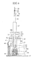
- a bracket 45 formed into a U-shape as illustrated in FIG 6 is fastened on the transverse plate (bottom plate) 31. Both end portions of a supporting shaft 46 are held by facing walls 45a, 45a of the bracket 45 in a rotatable manner about an axis line, and a pressure lever 47 is fastened to the supporting shaft 46. This pressure lever 47 has contact with the upper portion of the engagement shaft 44.
- a coil spring 48 for lowering a lever is arranged between the pressure lever 47 and the transverse plate 31. A tension spring force of this tension coil spring 48 is set to be larger than a spring force of the coil spring.
- An elevation position control lever 49 is fastened to the supporting shaft 46.
- This elevation position control lever 49 controls an elevation position of the engagement shaft 44 by the pressure lever 47 and sets the elevation positions of the measuring element shaft 35 and the measuring element for a lens frame 37 and the measuring element for a lens 38.
- This elevation position control lever 49 extends in the direction which is the same as that of the pressure lever 47.
- An actuator motor 50 is placed on the lower side of the elevation position control lever 49.
- This actuator motor 50 includes a motor main body 50a fastened on the transverse plate 31 and a shaft 51 which projects upwardly from the motor main body 50a and has the axis line parallel to the measuring element shaft 35.
- the elevation position control lever 49 has contact with the upper end of the shaft 51 by the tension spring force of the coil spring 48.
- a DC motor is used for this actuator motor 50.
- the shaft 51 moves upwardly by the normal rotation of the actuator motor 50 and the shaft 51 moves downwardly by the reverse rotation of the actuator motor 50.
- an origin detection signal from the above photosensor (origin detector) 9a, an origin detection signal from the photosensor 20c of the origin detector (origin detection unit), a displacement detection signal (position detection signal) from the detection head 26 of the linear scale 24, the displacement detection signal (position detection signal) from the detection head 42 of the linear scale 40 and the like are input to the arithmetic control circuit (control circuit) 52.
- the arithmetic control circuit 52 controls the driving of the driving motors 6, 18 and the actuator motor 50.
- a holder detector 53 as illustrated in FIG. 1 is set in one side wall of the slide frames 3.3 as a holder detector.
- a micro-switch and the like are used for the holder detector 53.
- the detection signal from the holder detector 53 is input into the arithmetic control circuit 52 as illustrated in FIG. 10A .
- reference number 54 is a start switch for measurement.
- the upper end of the shaft 51 of the actuator motor 50 is located in the lower end (bottom dead point) as illustrated in FIGs. 6-8 .
- the pressure lever 47 is biased to rotate downwardly about the supporting shaft 46 by the tension coil spring 48 having a spring force stronger than that of the coil spring 43.
- the pressure lever 47 thereby presses the measuring element shaft 35 downwardly via the engagement shaft 44 to locate the measuring element 37 for a lens frame and the measuring element 38 for a lens in the lower end.
- an eyeglass frame MF having right and left lens frames LF (RF) in FIG. 7 is placed between the slide frames 3, 3 in FIG. 1 (the eyeglass frame MF is not illustrated in FIG. 1 ) to sandwich the lens frames LF (RF) between the holding bars 3b1, 3b2 as illustrated in FIG. 7 .
- This holding method is similar to that in JP H10-328992A .
- the lens frames LF (RF) held between the holding bars 3b1, 3b2 are set to be located above the measuring element 37 for a lens frame before starting the measurement as illustrated in FIG. 7 . More specifically, the measuring element 37 for a lens frame is located in an initial position (A) lower than the lens frames LF (RF). Moreover, as illustrated in FIG. 7 , the measuring element 37 for a lens frame and the measuring element 38 for a lens are located in an initial position (i) which is the substantial center of the lens frames LF (RF) held between the holding bars 3b1, 3b2.
- the photosensor 9a detects the origin of the horizontal rotation of the rotation base 9 from the light flux from the light emitter 9b, and the origin sensor 20a detects the origin of the displaced position of the slider 15.
- the held portion of the lens frame by the holding bars 3b1, 3b2 has a height which is the lowest in the lens frame.
- the height of the V-groove Ym of the lens frames (LF) RF becomes a set height, namely, a lens frame shape measurement start position B.
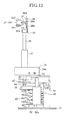
- the start switch 54 in FIG 10A is turned on, the arithmetic control circuit 52 normally rotates the actuator motor 50, and elevates the shaft 51 by a predetermined amount to the position in FIGs. 11-14 from the position in FIGs. 6-8 .
- the shaft 51 lifts the free end portion of the elevation position control lever 49 upward against the spring force of the tension coil spring 48, and turns the elevation position control lever 49 together with the supporting shaft 46.
- the pressure lever 47 turns together with the supporting shaft 46, and the free end portion is elevated by a predetermined amount
- the engagement shaft 44 follows the free end portion of the pressure lever 47 to be elevated by the spring force of the coil spring 43, so that the measuring element shaft 35 is elevated by a predetermined amount.
- the amount of elevation of the measuring element shaft 35 i.e., the amount of elevation of the shaft 51 by the actuator motor 50 becomes the amount L in which the leading end of the measuring element 37 for a lens frame is elevated to the height C facing the V-groove Ym in the above-described shape measurement start position (B) from the initial position (A) in FIG. 7 .
- the arithmetic control circuit 52 rotates the driving pulley 19 by controlling the driving of the driving motor 18, and displaces the slider 15 along the guide rail 14 by the wire 20 in FIGs. 2 , 5B .
- the slider 15 moves in the arrow A1 direction in FIG 7 . This movement is performed until the leading end of the measuring element 37 for a lens frame has contact with the V-groove Ym as illustrated in FIG. 12 in the shape measurement start position (B).
- the measuring element 37 for a lens frame has contact with the V-groove Ym by the spring force of the coil spring 23. Then, the driving motor 18 is stopped.
- the leading end of the measuring element 37 for a lens frame has contact with the V-groove Ym
- the load on the driving motor 18 is increased, so that the current flowing in the driving motor 18 is increased. Therefore, it can be detected that the leading end of the measuring element 37 for a lens frame has contact with the V-groove Ym by detecting the current change, and thus, the driving motor 18 is stopped.
- the arithmetic control circuit 52 normally rotates the actuator motor 50, and displaces the shaft 51 by a predetermined amount to the position in FIGs. 15-17 from the position in FIGs. 11-14 .
- the shaft 51 lifts the free end portion of the elevation position control lever 49 against the spring force of the tension coil spring 48, and turns the elevation position control lever 49 together with the supporting shaft 46.
- the pressure lever 47 turns together with the supporting shaft 46, the free end portion is elevated at predetermined amount, the free end portion of the pressure lever 47 moves away at predetermined amount from the engagement shaft 44, and the measuring clement shaft 35 becomes vertically displaceable.
- the arithmetic control circuit 52 controls the driving of the driving motor 6 to normally rotate the driving motor 6.
- the rotation of the driving motor 6 is transferred to the driven gear 5 via the pinion 7 and the timing belt 8, so that the driven gear 5 horizontally rotates together with the rotation base 9 (refer to FIG. 5A ).
- the slider 15 and a number of components arranged in the slider 15 horizontally rotate together with the rotation base 9, and the leading end of the measuring element 37 for a lens frame slides along the V-groove Ym.
- the displacement when the slider 15 is displaced from the origin position of the slider 15 becomes the same as the displacement of the leading end of the measuring element 37 for a lens frame. This displacement is obtained by the arithmetic control circuit 52 from the detection signal of the detection head 26 of the linear scale 24.
- the measurement (length) from the center of the measuring element shaft 35 to the leading end of the measuring element 37 for a lens frame is known, if the distance from the rotation center of the rotation base 9 when the slider 15 is in the origin to the leading end of the measuring element 37 for a lens frame is set in advance, even if the distance from the rotation center of the rotation base 9 to the leading end of the measuring element 37 for a lens frame is changed when the slider 15 is displaced along the guide rail 14, the change in this distance can be a moving radius pi.
- the shape (lens frame shape) of V-groove Ym of the lens frame LF (RF) in the circumferential direction can be obtained as lens frame shape information ( ⁇ i, ⁇ i) of a polar coordinate by obtaining the rotation angle ⁇ i of the rotation base 9 by the rotation of the driving motor 9 from the number of driving pulses of the driving motor 6 and obtaining the moving radius pi corresponding to the rotation angle ⁇ i.
- the curvature state in the vertical direction is obtained as a displacement in the vertical direction by the arithmetic control circuit 52 from the detection signal of the detection head 42 of the linear scale 40.
- This displacement in the vertical direction becomes a position Zi in the vertical direction.
- the shape of the lens frame LF (RF) is obtained as three-dimensional lens frame shape information ( ⁇ i, ⁇ i, Zi) by the arithmetic control circuit 52.
- a known lens holder disclosed in JP H10-328992A and JP H08-294855A can be used.
- a suction pad and a suction pad holding structure disclosed in JP H08-294855A can be adopted.
- the structure of this lens holder is not an essential to the present invention, so the description thereof will be omitted.
- a lens such as a demo-lens is held by the above-described lens holder, the lens holder is placed between the slider frames 3, 3, and the side wall of the lens holder in JP H10-328992A or the flange of the side portion in JP H08-294855A is sandwiched between, the fastening holding bar 3b1 and the movable holding bar 3b2.
- the lens held by the lens holder is directed on the lower side.
- use arithmetic control circuit 52 normally rotates the above-described actuator motor 50, so as to elevate the measuring element 37 for a lens frame from the initial position (A) to the height (B) illustrated in FIG. 7 . Accordingly, the measuring element 38 for a lens is elevated together with the measuring element 37 for a lens frame, and is elevated to a height corresponding to the rim of the lens held by the lens holder (not shown).
- the arithmetic control circuit 52 controls the driving of the driving motor 18, and transfers the rotation of the driving motor 18 to the slider 15 by the wire 20, and controls the displacement of the slider 15 along the guide rail 14 such that the measuring element 38 for a lens is displaced to have contact with the circumferential face of the lens Lm held by the lens holder (not shown) as illustrated in FIG. 18 .
- the driving motor 18 is stropped.
- control can be performed according to standard lens data previously obtained by an experiment and the like.
- the actuator motor 50 normally rotates to lift the free end portion of the elevation position control lever 49 to the position in FIGs. 15-17 against the spring force of the tension coil spring 48 from the position in FIG. 7 , and to rotate the supporting shaft 46.
- the supporting shaft 46 rotates the pressure lever 47, and lifts the free end portion of the pressure lever 47 in the direction which is the same as the direction of the free end portion of the elevation position control lever 49.
- the engagement shaft 44 is elevated together with the measuring element shaft 35 by the spring force of the coil spring 43, and the measuring element 38 for a lens is elevated, so that the measuring element 38 for a lens has contact with the back side refracting surface of the lens Lm.
- the slider 15 is displaced at a predetermined speed along the guide rail 14
- the measuring element 38 for a lens is displaced on the rim portion side along the back side refracting surface of the lens Lm
- the measuring element 38 for a lens is displaced to a position which is significantly separated from the rim of the back side refracting surface of the lens Lm.
- the crushing of the measuring element 37 for a lens frame to the lens Lm can be avoided by increasing the moving speed of the measuring element 38 for a lens on some lever because the spring force of the coil sprang 43 is week.
- the withdrawn position of the measuring element 38 for a. lens out of the back side refracting surface of the lens Lm can be determined if the linear scale 40 detects the position when the measuring element 38 for a leas is elevated.
- the position of the horizontal direction of the measuring element 3 for a lens in the withdrawn position can be obtained from the detection signal of the linear scale 24. Therefore, by the detection signals from the linear scales 24, 40 in the withdrawn positions, the position where the measuring element 38 for a lens separates from the back side refracting surface of the lens Lm can he obtained as three-dimensional coordinate data.
- the arithmetic control circuit 52 controls the driving of the driving motor 18 to transfer the rotation of the driving motor 18 to the slider 15 by the wire 20, and controls the displacement of the slide 15 along the guide rail 14 such that the measuring element 38 for a lens is moved to have contact with the circumferential face of the lens Lm held by the lens holder (not shown) as illustrated in FIG. 18 . Then, after the measuring element 38 for a lens has contact with the circumferential face of the lens Lm, the driving motor 18 is stopped.
- the pressure lever 47 accordingly turns together with the supporting shaft 46, the free end portion is elevated by a predetermined amount, and the free end portion of the pressure lever 47 separates by a predetermined amount from the engagement shaft 44, so that the measuring clement shaft 35 becomes vertically moveable.
- the step face 38a of the circumference of the lower end of the measuring element 38 for a ins has contact with the lower end of the edge of the lens Lm by the spring force of the coil spring 43.
- the arithmetic control circuit 52 controls the driving of the driving motor 6 to normally rotate the driving motor 6-
- the rotation of the driving motor 6 is transferred to the driven gear 5 via the pinion 7 and the timing belt 8, so that the driven gear 5 horizontally rotates together with the rotation base 9.
- the slider 5 and a number of components arranged in the slider 15 horizontally rotate together with the rotation base 9, and the measuring element 38 for a lens slides along the circumferential face (edge) of the lens Lm.
- the displacement when the slider 15 displaces from the origin position of the slider 15 becomes the same as the displacement of the leading end of the measuring element 37 for a lens frame.
- This displacement can be obtained by the arithmetic control circuit 52 from the detection signal of the detection head 26 of the linear scale 24.
- the change in this distance can be a moving radius ⁇ i.
- the circumferential face shape (lens shape) of the lens Lm can be obtained as lens shape information ( ⁇ i, ⁇ i) of a polar coordinate by obtaining the rotation angle ⁇ i of the rotation base 9 by the rotation of the driving motor 6 from the number or driving pulses of the driving motor 6 and obtaining the moving radius ⁇ i corresponding to the rotation angle ⁇ i.
- the curvature state in the vertical direction can be obtained as a displacement in the vertical direction by the arithmetic control circuit 52 from the detection signal of the detection head 42 of the linear scale 40.
- the displacement in the vertical direction becomes a position Zi in the vertical direction.
- the shape of the lens Lm can be accordingly obtained as three-dimensional lens shape information ( ⁇ i, ⁇ i, Zi) by the arithmetic control circuit 52.
- the arithmetic control circuit 52 calculates the three-dimensional circumferential length of the lens Lm which is a dummy lens from the lens shape information ( ⁇ i, ⁇ i, Zi).
- the three-dimensional circumferential length of the lens Lm which is a dummy lens is calculated by obtaining the three-dimensional lens shape information ( ⁇ i, ⁇ i. Zi); however, it is not limited thereto
- the curvature of the back side refracting surface fb of the lens Lm illustrated in FIG. 19 is calculated by the measurement, and the position Zi of the vertical direction of the edge of the lens Lm in the lens shape information ( ⁇ i, ⁇ i) can be obtained from the calculated curvature and the lens shape information ( ⁇ i, ⁇ i), so that the three-dimensional lens shape information ( ⁇ i, ⁇ i, Zi) can be obtained.
- the three-dimensional circumferential length of the lens Lm which is a dummy lens can be calculated from the three-dimensional shape information ( ⁇ i, ⁇ i, Zi).
- ⁇ i, ⁇ i, Zi the three-dimensional shape information
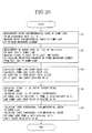
- the two-dimensional lens shape information ( ⁇ i, ⁇ i) is obtained in the rim shape measurement (outer circumferential shape measurement) of the lens Lm in Step S1, then the operation moves to Step S2.
- the arithmetic controls circuit 52 measures the curvature of the back side refracting face fb of the lens Lm illustrated in FIG. 19 .
- the operation of the actuator motor 50 is controlled similar to the measurement of the lens frame in (a) as described above, and the upper end of the measuring element for a lens is brought into contact with the back side refracting surface fb of the lens Lm held by the not shown lens holder with the spring force of the coil spring 43.
- the lens Lm is retained by a suction pad, and this suction pad is detachably attached to the not shown lens holder, so that the lends is held by the lens holder.
- it is set such that the vertically extending axis line (not shown) of the suction pad of the lens holder is aligned with the vertically extending axis line (shaft line O in FIG. 7 ) of the measuring element 38 for a lens when the slider 15 is in the origin position.
- the aligned position (aligned point) of the axis lines is set to an origin P0 in the X direction of the measurement (radium direction of lens Lm).
- the measuring element 38 for a lens is located in the initial position on the lowermost side.
- the upper end (leading end) position of the measuring element 38 for a lens is set as the initial position (C), and this initial position (C) is set to the origin Z0 in the Z direction (vertical direction) of the measurement in FIGs. 21(a), 21(b) .
- the arithmetic control circuit 52 controls the operation of the driving motor 18, and displaces the slider 15 along the guide rail 14 by the wire 20 which works with the driving motor 18, and the upper end (leading end) of the measuring element 38 for a lens is sequentially moved to the measurement points P2, P1 of the radius direction (X direction) of the lens Lm.
- This measurement point P2 is a position which is moved in the radius direction (X direction) of dire lens Lm at a distance X2 from the origin X0 in the X direction
- the measurement point P1 is a position which is moved in the radius direction (X direction) of the lens Lm at the distance X1 (X1 > X2) from the origin X0 in the X direction
- the arithmetic control circuit 52 calculates the heights Z2, Z1 in the Z direction (vertical direction) in the distances X2, X1 of the back side refracting surface fb of the lens Lm from the displacement detection signal from the linear scale 40, and the operation moves to Step S3.
- the heights Z2, Z1 in the Z-direction are distances from the origin Z0 in the Z-direction.
- the arithmetic control circuit 52 obtains a curve value from the curvature of the back side refracting surface fb of the lens Lm.
- the distance from the curvature center O1 of the back side refracting surface fb of the lens Lm to the origin Z0 in the Z-direction is ⁇ Z
- the height from the curvature center O1 to the measurement point P2 is Z1 + ⁇ Z
- the height from the curvature center O1 to the measurement point P1 is Z1 + ⁇ Z. Therefore, the coordinate of the measurement point P2 is (X2, Z2 + ⁇ Z) and the coordinate of the measurement point P1 is (X1, Z1 + ⁇ Z).
- the arithmetic control circuit 52 calculates by using a circular equation in order to obtain a curvature from the coordinate (X2, Z2 + ⁇ Z) of the measurement point P2 and the coordinate (X1, Z1 + ⁇ Z) of the measurement point P1.
- ⁇ Z can be obtained from this equation. Namely, ⁇ Z is as follows.
- ⁇ Z X ⁇ 2 2 - X ⁇ 1 2 + Z ⁇ 2 2 - Z ⁇ 1 2 Z ⁇ Z ⁇ 1 - Z ⁇ 2
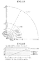
- the curve value of the eyeglass lens is set within a range from the curve of 1 to the curve of 8 as illustrated in FIG. 22 .
- the curvature radius R1-R8 from the curve of 1 to the curve of 8 is as illustrated in Table 1.
- the Z-direction difference ⁇ L ( ⁇ L- ⁇ L8) of the measurement points P1, P2 can be obtained corresponding to the curve of 1 to the curve of 8 as illustrated in Table 1.
- the Z-direction difference ( ⁇ L in FIG 21 ) of the measurement points P1, P2 is about 0.287 of ⁇ L1
- the curvature radius of the lens Lm as a demo-lens can be determined as 523mm of R1 corresponding to the curve of 1 (curve value 1).
- the Z-direction difference ( ⁇ L in FIG. 21 ) of the measurement points P1, P2 and the curve value Cv can be expressed in linear approximation and that equation is as follows.
- C ⁇ u ⁇ r ⁇ v ⁇ e v ⁇ a ⁇ l ⁇ u ⁇ e 3.3695 ⁇ Z - d ⁇ i ⁇ r ⁇ e ⁇ c ⁇ t ⁇ i ⁇ o ⁇ n d ⁇ i ⁇ f ⁇ f ⁇ ⁇ ⁇ ⁇ r ⁇ e ⁇ n ⁇ c ⁇ e ⁇ ⁇ L + 0.0809
- the relationship between the curve value Cv and the Z-direction difference ⁇ L ( ⁇ L1 - ⁇ L8) is linearly proportional as illustrated in FIG. 22B .
- the arithmetic control circuit 52 obtains the curve value of the back side refracting surface fb of the lens Lm, and the operation moves to Step S4.
- Step S4 the arithmetic control circuit 52 obtains the positional information Zbi in the Z-direction of the rim of the back side refracting surface fb of the lens Lm from the curve value Cv obtained according to the Z-direction difference ⁇ L ( ⁇ L1- ⁇ L8) and the lens shape information ( ⁇ i, ⁇ i), and the operation moves to Step S5.
- Step 5 the arithmetic control circuit 52 obtains the three-dimensional lens shape information ( ⁇ i, ⁇ i, Zbi) from the two-dimensional lens shape information ( ⁇ i, ⁇ i) and the positional information Zbi of the Z-direction of the rim of the back side refracting surface fb of the lens Lm obtained in Step S4, and the step is completed.
- the three-dimensional lens shape information ( ⁇ i, ⁇ i, Zbi) is stored in a memory.
- circular unprocessed eyeglasses are selected from an eyeglass lens prescription according to refracting information of the subject eyes of a person wearing eyeglasses, this unprocessed eyeglass lens is held between a pair of lens rotation shafts of the lens grinder (not shown), and the edge thickness Wi in a position corresponding to the two-dimensional lens shape information. ( ⁇ i, ⁇ i) of the unprocessed eyeglass lens is measured by an edge thickness measurement device of the lens grinder. Since a well-known configuration of the lens grinder can be adopted, the description thereof using a drawing will be omitted.
- the position Zci in the direction parallel to the lens rotation shaft of the front side refracting surface of the unprocessed eyeglass lens and the position Zdi in the direction parallel to the lens rotation shaft of the back side refracting surface of the unprocessed eyeglass lens are obtained.
- a known method can be adopted for obtaining these positions Zci, Zdi.
- the rim of the unprocessed eyeglass lens is grinded by the lens grinder (not shown) according to the two-dimensional lens shape information ( ⁇ i, ⁇ i), so as to form an eyeglasses lem having the lens shape information ( ⁇ i, ⁇ i, Wi).
- the engagement groove for a rimless frame such as Nylor and the like is formed on the circumferential face of the eyeglass lens having the lens shape information ( ⁇ i, ⁇ i, Wi) by using a grinding stone set in the lens grinder.
- the engagement groove is formed into the shape of the three-dimensional lens shape information ( ⁇ i, ⁇ i, Zbi) on the circumferential face of the eyeglass lens having the lens shape information ( ⁇ i, ⁇ i, Wi) according to the lens shape information ( ⁇ i, ⁇ i, Zci) or the lens shape information ( ⁇ i, ⁇ i, Zbi).
- the engagement groove is formed in a portion having a predetermined distance from the corner portion of the refracting surface and the outer circumferential face of one lens.
- the engagement groove which is formed on the circumferential face of the eyeglass lens having the lens shape information ( ⁇ i, ⁇ i, Wi) is formed to be the same as the engagement groove which is formed in the lens Lm such as a demo-lens. For this reason, it is not necessary to perform the curving process of the half-rim frame when mounting the half-rim frame of the grooved frame on the circumferential face of the eyeglass lens.
- the lens shape measurement device of the present embodiment includes the less holding unit, i.e., the lens holder (not shown) set in the measurement device main body 1, the measuring element 38 for a lens, which measures the rim shape of the lens Lm held in the lens holder, the measuring element shifter as a measurement element shifting unit (driving motor 6) which shifts along the outer circumferential face of the lens Lm, the position detector as a position detection unit (linear scales 24, 40) which detects the coordinate of the measurement element 38 for a lens shape, and the arithmetic control circuit 52 which obtains the circumferential face shape data of the lens Lm as two-dimensional information according to the detection signal from the position detector (linear scales 24, 40).
- the less holding unit i.e., the lens holder (not shown) set in the measurement device main body 1
- the measuring element 38 for a lens which measures the rim shape of the lens Lm held in the lens holder
- the measuring element shifter as a measurement element shifting unit (driving motor
- the arithmetic control circuit 52 controls the measuring element shifter (driving motor 6), and brings the measuring element 38 for a lens into contact with at least two points (measurement points P1, P2) of one of the two refracting surfaces of the lens Lm held in the lens holder, obtains the coordinate of the two points according to the detection signals from the position detector (linear scales 24, 40), and obtains the curve value Cv which is a curvature of one refracting surface of the lens from the coordinate of the two points.
- the three-dimensional shape of a half rim can be specified even if it is a grooved frame.
- the engagement groove which is formed on the circumferential face of the eyeglass lens having the lens shape information ( ⁇ i, ⁇ i, Wi) can be formed to be the same as the engagement groove which is formed in the lens Lm such as a demo-lens. For this reason, it is not necessary to perform the curving process and the like of the half-rim when mounting the half-rim of the grooved frame on the circumferential face of the eyeglass.
- the rim shape process date of the lens can be obtained from the curve value Cv of one refracting surface of the lens and the lens shape data ( ⁇ i, ⁇ i) of the outer circumferential face shape data of the lens.
- the lens shape measurement device it is not always necessary to obtain the rim shape process data of the lens by the lens shape measurement device, and can be obtained by a lens rim grinder. Therefore, if the curve value Cv of one refracting surface of the lens is obtained, the shape of the engagement groove which is formed on the circumferential face of the eyeglass lens can be specified by the lens shape information ( ⁇ i, ⁇ i, Wi) with the lens rim grinder, so that it is not always necessary to obtain the rim shape process data of the lens by the lens shape measurement device.
- the device main body 1 includes the lens frame holder and the measuring element 37 for a lens frame which measures the three-dimensional shape of the circumferential direction of the V-groove Ym of the lens frame LF (RF) held in the less frame holder.
- the measuring element 38 for a lens is set in the measuring element 37 for a lens frame.
- the measuring element 38 for a lens is set in the measuring element 37 for a lens frame, so that the configuration of the measurement unit can be simplified.
- the arithmetic control circuit 52 obtains the three-dimensional edge corner shape data (lens shape information ( ⁇ i, ⁇ i, Zbi)) of the outer circumferential face and the refracting surface of the lens Lm from the curve value Cv and the circumferential shape data (lens shape information ( ⁇ i, ⁇ i)) of the lens Lm, so that the thres-dimensional groove position data in the circumferential direction and the edge direction to the outer circumferential face of the lens Lm can be obtained according to the three-dimensional edge corner shape data (lens shape information ( ⁇ i, ⁇ i, Zbi)).
- the edge corner data of the outer circumferential face and the refracting surface of the lens Lm is configured from the circumferential shape of the lens Lm and the shape in the optical axis direction of the lens Lm. Therefore, the three-dimensional edge corner shape data (lens shape information ( ⁇ i, ⁇ i, Zbi)) is configured from the lens shape data ( ⁇ i, ⁇ i) along the circumferential face of the lens Lm and the data Zbi in the optical axis direction of the les Lm, so that it can be the three-dimensional shape data of the edge corner between the refracting surface and the outer circumferential face of the lens.
- the measuring element 38 for a lens includes the circumferential measurement portion (shaft-like measurement portion 38a) which has contact with the outer circumferential face of the lens Lm and the corner measurement portion (step face 38d) which has contact with the edge corner between one refracting surface and the outer circumferential face of the lens Lm.
- the arithmetic control circuit 52 controls the operation of the measurement portion shifter (driving motor 6), brings the outer circumferential measurement portion (shaft-like measurement portion 38a) into contact with the outer circumferential face, shifts the corner measurement portion (step face 38d) in the circumferential direction while brining the corner measurement portion into contact with the edge corner, and obtains the three-dimensional edge corner shape data (lens shape information ( ⁇ i, ⁇ i, Zbi)) according to the detection signal from the position detector (linear scale 24, 40).
- the three-dimensional edge corner shape data (lens shape information ( ⁇ i, ⁇ i, Zbi)) can be easily obtained.
- the lens frame shape measurement device of the present embodiment can include a material input unit which inputs a material of a lens.
- a material input unit which inputs a material of a lens.
- a liquid crystal display Ldp is set in the main body case Hc as a display unit, and a material selection menu of a lens material is displayed on the liquid crystal display Ldp.
- a key board Kb which selects a lens material from the material selection menu can be provided, and this key board Kb can be a lens material input unit.
- This key board Kb includes "- +" switch Sa or " ⁇ ” cursor key cl, “ ⁇ ' cursor key c2, and the operation of "- +” switch Sa or " ⁇ ” cursor key c1, " ⁇ ” cursor key c2 is input into the arithmetic control circuit 52 in FIG. 10C .
- the arithmetic control circuit 52 controls the liquid crystal display Ldp, and displays the lens material selection menu such as "glass”, “plastic”, “high refractive index plastic”, “polycarbonate” and “acrylic” on the liquid crystal display Ldp.
- the arithmetic control circuit 52 selects any or the lens materials such as “glass”, “plastic”, “high refractive index plastic”, “polycarbonate”, “acrylic” displayed on the liquid crystal display Ldp by the operation of "- +" switch Sa or " ⁇ " cursor key cl, " ⁇ ” cursor key c2.
- a touch sensor can be provided on the liquid crystal display Ldp, and this touch sensor can be used as the lens material input unit.
- the arithmetic control circuit 52 obtains the three-dimensional edge thickness data in the circumferential direction of the lens Lm from the circumferential face shape data and the lens material input by the material input unit, and the three-dimensional groove position data in the circumference direction and the edge direction to the outer circumferential face of the lens can be obtained according to the three-dimensional edge corner snaps data (lens shape information ( ⁇ i, ⁇ i, Zbi)) and the three-dimensional edge thickness data (lens shape information ( ⁇ i, ⁇ i, Zbi)).
- the groove process on the circumferential face of the eyeglass lens can be accurately conducted by using the three-dimensional groove position data.
Landscapes
- Engineering & Computer Science (AREA)
- Physics & Mathematics (AREA)
- General Physics & Mathematics (AREA)
- Chemical & Material Sciences (AREA)
- Ceramic Engineering (AREA)
- Inorganic Chemistry (AREA)
- Mechanical Engineering (AREA)
- Eyeglasses (AREA)
- A Measuring Device Byusing Mechanical Method (AREA)
- Length Measuring Devices With Unspecified Measuring Means (AREA)
Abstract
Description
- The present invention relates to a lens shape measurement device which measures a lens shape of eyeglasses.
- In general, as eyeglass frames, a rim frame (full rim frame), a rimless frame (two-point frame), a grooved frame (half-rmi and Nylor) and the like are known.
- In the grooved frame, for example, a retention groove which extends in the circumferential direction is formed on an outer circumferential face of a lens, a half-rim is firmly affixed to the upper side of the lens (eyeglass lens), and Nylor which is supported by both ends of the half-rim is arranged in the retention groove in the lower side of the lens, so that the lens is affixed to the half rim by Nylor.
- For this grooved frame, it is necessary to form the retention groove extending in the circumferential direction on the outer circumferential face of the lens. This retention groove is obtained by forming a circular groove extending in the circumferential direction on the outer circumferential face of the lens by a cutter and the like after the rim of the circular unprocessed eyeglass lens is formed into the lens (eyeglass lens) shape by a lens gander according to lens shape data.
- Meanwhile, a lens shape measurement device disclosed in
JP H10-166250A JP H10-166250A - In this lens shape measurement device, a moving radius ρi (a change in a distance from a geometric center of a lens frame to a V-groove) relative to a rotation angle θi of the rotation base and a displacement Zi in the up and down direction can be obtained as lens frame shape data (θi, ρi, Zi) by moving the measuring element for a lens frame along the V-groove.
- As the above lens shape measurement device, a device in which a lens holder (lens holding unit) which holds a tens is detachably attached to a main body and a measuring element for a lens is arranged in a slider to freely rise up and fall is known. In this lens shape measurement device, the measuring element for a lens is set up and has contact with the outer circumferential face of the lens held by the lens holder, and the rotation base horizontally rotates by the rotation and driving motor, so that the measuring element for a lens is slidably moved in the circumferential direction along the outer circumferential face of the lens, and the moving radius ρi (a change in a distance from a geometric center or an optical center of a lens to a rim) of the lens relative two the rotation angle θi of the rotation base can be obtained as lens circumferential face shape data (θi, ρi).
- In this lens shape measurement device, the shape data of the lens frame is obtained as the above-described three-dimensional shape data; however, the shape data of the lens is two dimensionally obtained as a moving radius ρi relative to a rotation, angle θi.
- Consequently, in order to process the retention groove on the lens, it is necessary to hold an unprocessed eyeglass lens between lens rotation shafts which are mounted on a lens grinder in series, rotate the lens rotation shafts and the unprocessed eyeglass lens together at a predetermined angle Δθ before grinding the rim portion of the unprocessed eyeglass lens according to the circumferential face shape data (θi, ρi) by a grinding stone, and measure positional data in the direction along the lens rotation shafts of the front side refracting surface and the back side refracting surface in the moving radius ρi of the unprocessed eyeglass lens by an edge thickness measurement unit.
- Meanwhile, when ordering eyeglasses in opticians, for example, it is general to select one's favorite eyeglasses from displayed sample eyeglasses. In an actual situation for such sample eyeglasses, demo-tenses (dummy lenses) are attached to a frame or a rimless frame. The circumferential face (edge face) of the demo-lenses attached to the frame (rim) is formed in a shape along the three-dimensional shape of the frame (rim).
- However, an actual eyeglass lens has a difference in a curvature of a refracting surface according to a prescription, of the eyeglasses, or in an edge thickness according to a rotation center of a lens in the grinding of the rim of the lens. For this reason, in a grooved frame, when mounting an actual eyeglass lens on a half-rim, a bending process is performed to the half rim according to the rim shape of the eyeglass lens.
- However, it is desirable to mount the eyeglass lens on the half-rim frame without performing such a bending process for a half-rim. In order to achieve that, it is necessary to measure a three-dimensional shape of a half-rim; however, in the above-described measurement device, a three-dimensional shape of a half-rim can not be measured.
- It is, therefore, an object of the present invention to provide a lens shape measurement device which can specify a three-dimensional shape of a haif-rim frame even in a grooved frame by obtaining a circumferential face shape and a curvature of a refracting surface of a lens such as a demo-lens.
- In order to achieve the above object, a lens shape measurement device of the present invention includes a lens holder set in a measurement device main body, a measuring element for a lens configured to measure a rim shape of a lens held in the less holder, a measuring element shiner configured to displace the measuring element for a lens along an outer circumferential face of the lens, a position detector configured to detect a coordinate of the measuring element for a lens, and an arithmetic control circuit configured to obtain circumferential face shape data of the lens according to a detection signal from the position detector as two-dimensional information. Moreover, the arithmetic control circuit is configured to bring the measuring element for a lens into contact with at least two points of one uf two refracting surfaces of the lens held in the lens holder by controlling the measuring element shifter, obtain coordinates of the two points according to the detection signal from the position detector, and obtain a curve value which is a curvature of one refracting surface of the lens from the coordinates of the two points.
- According to the present invention, the three-dimensional shape of a half-rim can be specified by obtaining the curvature of a refracting face and a circumferential face shape of a lens such as a demo-lens even in a grooved frame.
-
-
FIG. 1 is a partially schematic perspective view illustrating a lens shape measurement device according to the present invention. -
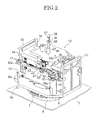
FIG. 2 is a perspective view illustrating a measurement mechanism of the lens shape measurement device inFIG. 1 . -
FIG. 3 is a front view of the measurement mechanism inFIG. 2 . -
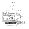
FIG. 4 is a back view of the measurement mechanism inFIG. 2 . -
FIG. 5 is a right side view of the measurement mechanism inFIG. 4 . -
FIG. 5A is a pattern diagram illustrating a driver of a rotation base of the measurement mechanism inFIG. 2 . -
FIG. 5B is a pattern diagram describing a slider driving mechanism inFIG. 2 -
FIG. 5C is a plan view ofFIG. 5B . -
FIG. 5D is a schematic view describing an origin detector of the slider inFIG. 2 . -
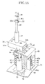
FIG. 6 is a perspective view illustrating a moving-up-and-down mechanism of a measuring element inFIG. 2 . -
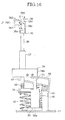
FIG. 7 is a view describing measurement of a lens frame by the moving-up-and-down mechanism inFIG. 6 . -
FIG. 8 is a left side view ofFIG. 7 . -
FIG. 9 is a partially schematic perspective view illustrating a measuring element for a lens illustrated inFIG. 1 . -
FIG. 10 is a side view ofFIG. 9 . -
FIG. 10A is a control circuit diagram of the lens shape measurement device illustrated inFIG. 1 . -
FIG. 10B is a view describing a part of a lens material input unit provided in the lens shape measurement device illustrated inFIG. 1 . -
FIG. 10C is a control circuit diagram having the lens material input unit inFIG. 10B . -
FIG. 11 is a perspective view describing a function of the moving-up-and-down mechanism of the measuring element inFIG. 6 . -
FIG. 12 is a view describing measurement of a lens frame by the moving-up-and-down mechanism inFIG. 11 . -
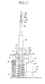
FIG. 13 is a view describing a linear scale of the moving-up-and-down mechanism inFIG. 11 . -
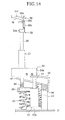
FIG. 14 is a right side view ofFIG. 13 . -
FIG. 15 is a perspective view describing the function of the moving-up-and-down mechanism of the measuring element inFIG. 6 . -
FIG. 16 is a view describing measurement of a lens frame by the moving-up-and-down mechanism inFIG. 15 . -
FIG. 17 is a left side view ofFIG. 16 . -
FIG. 18 is a view describing measurement of a lens by the moving-up-and-down mechanism inFIG. 2 . -
FIG. 19 is a view describing measurement of a lens by the moving-up-and-down mechanism inFIG. 2 . -
FIG. 20 is a flow chart for obtaining a curvature of a refracting surface of a lens by the lens shape measurement device inFIGs. 1-5 . -
FIG. 21A is a view for obtaining a curvature of a lens by the measurement of the lens shape measurement device inFIGs. 1-5 . -
FIG. 21B is a partially enlarged view ofFIG. 21A . -
FIG. 22A is a view describing a curve value of an eyeglass lens. -
FIG. 22B is a characteristic line view illustrating a relationship between a curve value inFIG. 22A and a difference between two measurement points of a refracting surface of a lens. Best Mode for Carrying Out the Invention - Hereinafter, an embodiment of the present invention will be described with reference to the drawings.
- A lens shape measurement device according to the present invention is used for measuring a shape of a lens such as a template, a demo-lens or a lens frame. In this case, a distance (diameter) from a geometric center of a lens to a circumferential face of a lens is changed in a plurality of positions in the circumferential direction of the lens, so that a diameter in which this distance is changed can be a moving radius.
FIG. 1 illustrates a lens shape measurement device which measures this moving radius. The lens shape measurement device includes a measurement devicemain body 1. - This measurement device
main body 1 includes in a lower portion thereof acase portion 1a for housing the measurement mechanism and a lenssame holding mechanism 1b provided above the case portion, 1a. Thecase portion 1a inFIG. 1 includes inside thereof a bottom portion provided with abase 2 illustrated inFIG. 2 . - The lens
frame retaining mechanism 1b includes a pair of parallel guide rods (guide members) 1c, 1c fastened to the case portion. Slide frames 3, 3 are retained by theguide members longitudinal walls lens frame holder 3b which holds a lens frame as a lens frame holding unit. Thislens frame holder 3b includes a lower side holding bar 3b1 which projects from thelongitudinal wall 3a and an upper side holding bar 3b2 which is attached to theslide frame 3 in operable and closable manner with respect to the holding bar 3b1 from the upper side. Thelens frame holder 3b is attached to each of right and left lens frames of not shown eyeglasses. In addition, as the lensframe holding mechanism 1b, a configuration disclosed inJP H10-328992A frame holding mechanism 1b is omitted. - A
measurement mechanism 1d illustrated inFIGs. 2-5 is installed on thebase 2. Thismeasurement mechanism 1d includes abase supporting member 4 fastened on thebase 2. Thisbase supporting member 4 includes a large diameter drivengear 5 to be horizontally rotatable about a vertical axis. Thebase 2 includes a drivingmotor 6 schematically illustrated inFIG. 5A adjacent to the driven gear (timing gear) 5. This drivingmotor 6 includes an output shaft 6a. A pinion (timing gear) 7 is fastened to the output shaft 6a. Atiming belt 8 is stretched over thepinion 7 and the drivengear 5. - Upon the driving of the driving
motor 6, the rotation of the output shaft 6a of the drivingmotor 6 is transferred to the drivengear 5 via thepinion 7 and thetiming belt 8, and the drivengear 5 rotates. In addition, the drivingmotor 6 is a biphasic stepping motor. - As illustrated in
FIGs 2-5 , arotation base 9 is integrally fastened on the drivengear 5. Thisrotation base 9 includes aphotosensor 9a as an origin detector i.e., an origin detection unit. In this case, for example, alight emitter 9b for indicating an origin position is placed on thebase 2 as a light emitting unit. A linear or point-like light flux is irradiated from thelight emitter 9b upwardly as an origin mark, and if thephotosensor 9a detects the light flux as an origin mark, the origin position of the horizontal rotation of therotation base 9 can be obtained. The origin detector includes thephotosensor 9a and thelight emitter 9b. As an origin detector, known arts such as a transparent photosensor, a refracting type photosensor or an adjacent photosensor can be adopted. - Facing parallel
rail attachment plates FIGs. 2-4 are integrally fastened to both of the end portions of therotation base 9 in the longitudinal direction. As illustrated inFIG 3 , end portions of aside plate 12 in the longitudinal direction are fastened to one side portion of therail attachment plate 10 and one side portion of therail attachment plate 11. As illustrated inFIG. 4 , end portions of aside plate 13 in the longitudinal direction are fastened to the other side portion of therail attachment plate 10 and the other side portion of therail attachment plate 11. - As illustrated in
FIGs. 2-4 , a pair of parallel shaft-like guide rails 14, 14 are horizontally arranged between the upper portions of the facingrail attachment plates guide rail 14 are fastened to therail attachment plates slider 15 is retained by the guide rails 14, 14 to be movable in the longitudinal direction. - Moreover, as illustrated in
FIGs. 2 ,3 , a pulley supportingplate portion 12a which horizontally projects towards the side is integrally formed with theside plate 12 adjacent to therail attachment plate 10 by bending, and abracket 16 for attaching a motor is fastened to theside plate 12 adjacent to therail attachment plate 11. - A driven
pulley 17 is attached to the pulley supportingplate portion 12a to be horizontally rotatable about an axis line extending up and down- An upper end portion of a drivingmotor 18 for moving a slider is fastened to thebracket 16. A DC motor is used for this drivingmotor 18. The axis line of theoutput shaft 18a of the drivingmotor 18 is vertically directed, and a drivingpulley 19 is attached to theoutput shaft 18a as illustrated inFIGs. 5B, 5C . - A
circular wire 20 is stretched over thepulleys wire 20 is held by a shaft-likewire holding member 21. Thiswire holding member 21 is fastened to theslider 15 viabrackets 22, 22'. Both of the end portions of thewire 20 are connected via acoil spring 23. Thereby, upon the normal rotation or the reverse rotation of the drivingmotor 18, theoutput shaft 18a and the drivingpulley 19 normally rotate or reversely rotate, so that theslider 15 is displaced right or left inFIG. 3 . - As illustrated in
FIG. 5D , anorigin sensor 20a which detects an origin of a displaced position (displacement) of theslider 15 is arranged between the bracket 22' and theside plate 12 as an origin detection unit, i.e., an origin detector. A reflection type sensor is used for thisorigin sensor 20a. This sensor includes arejection plate 20b having a slit-like reflection face (not shown) extending up and down, and areflection type photosensor 20c having a light emitting element and a light receiving element. Therefection plate 20b is set in the bracket 22' and the photosensor 20c is set in theside plate 12. - As the
origin sensor 20a, a known technique such as a transparent photosensor and a proximity photosensor can be adopted. - A supporting
plate portion 13a which horizontally projects to the side as illustrated inFIG. 5 is integrally formed in the central portion of theside plate 13 inFIG. 4 in the longitudinal direction by bending. Alinear scale 24 which detects the displaced position of theslider 15 of the horizontal direction in the extending direction of theguide rail 14 is arranged between theside plate 13 and theslider 15 as illustrated inFIG 4 . Thislinear scale 24 functions as a position detector (position detection unit) which is used when detecting a plurality of positions in the circumferential direction of the circumferential face of the lens, i.e., a moving radius detection sensor (moving radius detector) for use when detecting a moving radius of a lens - This
linear scale 24 includes a shaft-likemain scale 25 held by theslider 15 parallel to theguide rail 14 and adetection head 26 which is fastened to the supportingplate portion 13a and reads the positional information of themain scale 25. Thisdetection head 26 detects the displaced position of theslider 15 in the horizontal direction from the information for detecting the position of themain scale 25. For example, a known magnetic scale or optical scale can be used for thislinear scale 24. - For instance, in a magnetic scale, a magnetic pattern S, N is alternately provided at minute intervals as information for detecting a position (information for detecting displacement) in the axis line direction of the
main scale 25, and the magnetic pattern is detected by a detection head (a head for detecting a magnetic change) 26, so that the displacement (displaced position) of theslider 15 can be detected. Meanwhile, in an optical scale, themain scale 25 is formed in a plate-like form and fine interval slits are provided in the longitudinal direction of themain scale 25, and a light emitting element and a light receiving element are placed to sandwich themain scale 25 and the light from the light emitting element is detected by the light receiving element via the slits of themain scale 25, so that the displacement (displaced position) of theslider 15 can be detected by obtaining the number of slits. - The
slider 15 includes in the substantial center thereof a throughhole 15a as illustrated inFIG 2 . Aguide tube 27 extending vertically is inserted into thethorough hole 15a. A supportingframe 28 is arranged on the lower side of theslider 15 as illustrated inFIG. 4 . This supportingframe 28 includeslongitudinal frames slider 15 and a transverse board (bottom plate) 31 fastened to the lower end portions of thelongitudinal frames - Lower end portions of a pair of parallel shaft-like supporting
members FIG. 8 ). A holding member (connection member) 33 is fastened to the upper end portions of the supportingmembers longitudinal wall 34a of aguide supporting member 34 having a L-shaped side face is fastened to the holdingmember 33. The lower end portion of theguide tube 27 is fastened on a transverse wall (upper wall) 34b of theguide supporting member 34. - A measuring
element shaft 35 expending vertically is fitted into theguide tube 27 in a vertically movable manner, and a measuringelement attachment member 36 is integrally set in the upper end portion of the measuringelement shaft 35. This measuringelement attachment member 36 includes an L-shape having anattachment portion 36a vertically arranged in the upper end portion of the measuringelement shaft 35 and avertical portion 36b extending upward from theattachment portion 36a. A measuringelement 37 for a lens frame is integrally set in the upper end portion of thevertical portion 36b parallel to theattachment portion 36a. - A measuring
element 38 for a lens which projects upwardly is integrally set in the upper end of the measuringelement attachment member 36 as illustrated inFIGs. 9, 10 . This measuringelement 38 includes a shaft-like measurement portion 38a attached on the upper end of thevertical portion 36b of the measuringelement attachment member 36 parallel to the axis line of the measuringelement shaft 35, a taperedportion 38b arranged on the upper end portion of the shaft-like measurement portion 38a, and a small diameter holeengagement shaft portion 38c attached on the upper end of the taperedportion 38b. The upper end (leading end) portion of the holeengagement shaft portion 38c is formed into a hemisphere shape, and a leading end 38c1 is aligned with the axis line of the shaft-like measurement portion 38b. Astep face 38d as a corner measurement portion is arranged on the upper end of the measuringelement attachment member 36 in the outer circumference of the base portion of the shaft-like measurement portion 38a The edge corner of the lens Lm has contact with the corner between the shaft-like measurement portion 38a and thestep face 38d when measuring the shape of the lens Lm by the measuring element for a lens. - The
arithmetic control circuit 52 controls the driving of the measuring element movement unit (driving motor 6) such that the circumferential face measurement portion (shaft-like measurement portion 38a) has contact with the outer circumferential face and is moved in the circumferential direction while bringing the corner measurement portion (step face 38d) into contact with the edge corner. As illustrated inFIGs. 6-8 , abracket 39 is fastened to the lower end portion of the measuringelement shaft 35. Moreover, as illustrated inFIG 13 , alinear scale 40 which detects a displaced position in the vertical direction is placed between thebracket 39 and theguide supporting member 34 as a position defector (position detection unit) in the vertical direction, i.e., a height detection sensor (a height detector of a height detection unit). - This
linear scale 40 includes a shaft-likemain scale 41 placed in parallel with the measuringelement shaft 35 toward up and down and adetection head 42 which detects displaced positions of the measuringelements main scale 41 in the vertical direction. Themain scale 41 has the upper end portion fastened to the holdingmember 33 and the lower end portion fastened (held) to thebracket 39. Thedetection head 42 is held by the holdingmember 33. For thislinear scale 40, a magnetic scale or an optical scale can be adopted similar to the above-describedlinear scale 24. - As illustrated in
FIGs. 6-8 , acoil spring 43 which biases the measuringelement shaft 35 upwardly is arranged between thebracket 39 and the transverse plate (bottom plate) 31. Anengagement shaft 44 which is located above thebracket 39 and is orthogonal to the measuringelement shaft 35 is attached in the vicinity of the lower end portion of the measuringelement shaft 35. Abracket 45 formed into a U-shape as illustrated inFIG 6 is fastened on the transverse plate (bottom plate) 31. Both end portions of a supportingshaft 46 are held by facingwalls bracket 45 in a rotatable manner about an axis line, and apressure lever 47 is fastened to the supportingshaft 46. Thispressure lever 47 has contact with the upper portion of theengagement shaft 44. Moreover, acoil spring 48 for lowering a lever is arranged between thepressure lever 47 and thetransverse plate 31. A tension spring force of thistension coil spring 48 is set to be larger than a spring force of the coil spring. - An elevation
position control lever 49 is fastened to the supportingshaft 46. This elevationposition control lever 49 controls an elevation position of theengagement shaft 44 by thepressure lever 47 and sets the elevation positions of the measuringelement shaft 35 and the measuring element for alens frame 37 and the measuring element for alens 38. This elevationposition control lever 49 extends in the direction which is the same as that of thepressure lever 47.
Anactuator motor 50 is placed on the lower side of the elevationposition control lever 49. Thisactuator motor 50 includes a motormain body 50a fastened on thetransverse plate 31 and ashaft 51 which projects upwardly from the motormain body 50a and has the axis line parallel to the measuringelement shaft 35. The elevationposition control lever 49 has contact with the upper end of theshaft 51 by the tension spring force of thecoil spring 48. - In addition, a DC motor is used for this
actuator motor 50. Theshaft 51 moves upwardly by the normal rotation of theactuator motor 50 and theshaft 51 moves downwardly by the reverse rotation of theactuator motor 50. - As illustrated in
FIG. 10A , an origin detection signal from the above photosensor (origin detector) 9a, an origin detection signal from the photosensor 20c of the origin detector (origin detection unit), a displacement detection signal (position detection signal) from thedetection head 26 of thelinear scale 24, the displacement detection signal (position detection signal) from thedetection head 42 of thelinear scale 40 and the like are input to the arithmetic control circuit (control circuit) 52. thearithmetic control circuit 52 controls the driving of the drivingmotors actuator motor 50. - A
holder detector 53 as illustrated inFIG. 1 is set in one side wall of the slide frames 3.3 as a holder detector. A micro-switch and the like are used for theholder detector 53. The detection signal from theholder detector 53 is input into thearithmetic control circuit 52 as illustrated inFIG. 10A . In the figure,reference number 54 is a start switch for measurement. - Hereinafter, a function of such a lens shape measurement device will be described.
- Before the measurement of a lens frame shape of eyeglasses or a lens shape such as a demo-lens is performed in the lens shape measurement device, the upper end of the
shaft 51 of theactuator motor 50 is located in the lower end (bottom dead point) as illustrated inFIGs. 6-8 . In this position, thepressure lever 47 is biased to rotate downwardly about the supportingshaft 46 by thetension coil spring 48 having a spring force stronger than that of thecoil spring 43. Thepressure lever 47 thereby presses the measuringelement shaft 35 downwardly via theengagement shaft 44 to locate the measuringelement 37 for a lens frame and the measuringelement 38 for a lens in the lower end. - When measuring a lens frame shape of eyeglasses by this lens shape measurement device, as described in
JP H10-328992A FIG. 7 is placed between the slide frames 3, 3 inFIG. 1 (the eyeglass frame MF is not illustrated inFIG. 1 ) to sandwich the lens frames LF (RF) between the holding bars 3b1, 3b2 as illustrated inFIG. 7 . This holding method is similar to that inJP H10-328992A - The lens frames LF (RF) held between the holding bars 3b1, 3b2 are set to be located above the measuring
element 37 for a lens frame before starting the measurement as illustrated inFIG. 7 . More specifically, the measuringelement 37 for a lens frame is located in an initial position (A) lower than the lens frames LF (RF). Moreover, as illustrated inFIG. 7 , the measuringelement 37 for a lens frame and the measuringelement 38 for a lens are located in an initial position (i) which is the substantial center of the lens frames LF (RF) held between the holding bars 3b1, 3b2. - In this position, the
photosensor 9a detects the origin of the horizontal rotation of therotation base 9 from the light flux from thelight emitter 9b, and theorigin sensor 20a detects the origin of the displaced position of theslider 15. - In addition, even if the lens frame is curved in the three dimensional direction, the held portion of the lens frame by the holding bars 3b1, 3b2 has a height which is the lowest in the lens frame. In this held portion, the height of the V-groove Ym of the lens frames (LF) RF becomes a set height, namely, a lens frame shape measurement start position B.
- From this state, the
start switch 54 inFIG 10A is turned on, thearithmetic control circuit 52 normally rotates theactuator motor 50, and elevates theshaft 51 by a predetermined amount to the position inFIGs. 11-14 from the position inFIGs. 6-8 . In this case, theshaft 51 lifts the free end portion of the elevationposition control lever 49 upward against the spring force of thetension coil spring 48, and turns the elevationposition control lever 49 together with the supportingshaft 46. - Accordingly, the
pressure lever 47 turns together with the supportingshaft 46, and the free end portion is elevated by a predetermined amount By this elevation of the free end portion of thepressure lever 47, theengagement shaft 44 follows the free end portion of thepressure lever 47 to be elevated by the spring force of thecoil spring 43, so that the measuringelement shaft 35 is elevated by a predetermined amount. - The amount of elevation of the measuring
element shaft 35, i.e., the amount of elevation of theshaft 51 by theactuator motor 50 becomes the amount L in which the leading end of the measuringelement 37 for a lens frame is elevated to the height C facing the V-groove Ym in the above-described shape measurement start position (B) from the initial position (A) inFIG. 7 . - Then, the
arithmetic control circuit 52 rotates the drivingpulley 19 by controlling the driving of the drivingmotor 18, and displaces theslider 15 along theguide rail 14 by thewire 20 inFIGs. 2 ,5B . In this case, theslider 15 moves in the arrow A1 direction inFIG 7 . This movement is performed until the leading end of the measuringelement 37 for a lens frame has contact with the V-groove Ym as illustrated inFIG. 12 in the shape measurement start position (B). Moreover, in a state in which the leading end of the measuringelement 37 for a lens frame has contact with the V-groove Ym, the measuringelement 37 for a lens frame has contact with the V-groove Ym by the spring force of thecoil spring 23. Then, the drivingmotor 18 is stopped. - In addition, when the leading end of the measuring
element 37 for a lens frame has contact with the V-groove Ym, the load on the drivingmotor 18 is increased, so that the current flowing in the drivingmotor 18 is increased. Therefore, it can be detected that the leading end of the measuringelement 37 for a lens frame has contact with the V-groove Ym by detecting the current change, and thus, the drivingmotor 18 is stopped. - After that, the
arithmetic control circuit 52 normally rotates theactuator motor 50, and displaces theshaft 51 by a predetermined amount to the position inFIGs. 15-17 from the position inFIGs. 11-14 . In this case, theshaft 51 lifts the free end portion of the elevationposition control lever 49 against the spring force of thetension coil spring 48, and turns the elevationposition control lever 49 together with the supportingshaft 46. - Accordingly, the
pressure lever 47 turns together with the supportingshaft 46, the free end portion is elevated at predetermined amount, the free end portion of thepressure lever 47 moves away at predetermined amount from theengagement shaft 44, and the measuringclement shaft 35 becomes vertically displaceable. - Next, the
arithmetic control circuit 52 controls the driving of the drivingmotor 6 to normally rotate the drivingmotor 6. The rotation of the drivingmotor 6 is transferred to the drivengear 5 via thepinion 7 and thetiming belt 8, so that the drivengear 5 horizontally rotates together with the rotation base 9 (refer toFIG. 5A ). - With this rotation of the
rotation base 9, theslider 15 and a number of components arranged in theslider 15 horizontally rotate together with therotation base 9, and the leading end of the measuringelement 37 for a lens frame slides along the V-groove Ym. In this case, since theslider 15 moves along theguide rail 14 together with the measuringelement 37 for a lens frame, the displacement when theslider 15 is displaced from the origin position of theslider 15 becomes the same as the displacement of the leading end of the measuringelement 37 for a lens frame. This displacement is obtained by thearithmetic control circuit 52 from the detection signal of thedetection head 26 of thelinear scale 24. - Moreover, since the measurement (length) from the center of the measuring
element shaft 35 to the leading end of the measuringelement 37 for a lens frame is known, if the distance from the rotation center of therotation base 9 when theslider 15 is in the origin to the leading end of the measuringelement 37 for a lens frame is set in advance, even if the distance from the rotation center of therotation base 9 to the leading end of the measuringelement 37 for a lens frame is changed when theslider 15 is displaced along theguide rail 14, the change in this distance can be a moving radius pi. - Therefore, the shape (lens frame shape) of V-groove Ym of the lens frame LF (RF) in the circumferential direction can be obtained as lens frame shape information (θi, ρi) of a polar coordinate by obtaining the rotation angle θi of the
rotation base 9 by the rotation of the drivingmotor 9 from the number of driving pulses of the drivingmotor 6 and obtaining the moving radius pi corresponding to the rotation angle θi. - When the leading end of the measuring
element 37 for a lens frame slides along the V-groove Ym, if the lens frame LF (RF) has a curvature in the vertical direction, the curvature state in the vertical direction is obtained as a displacement in the vertical direction by thearithmetic control circuit 52 from the detection signal of thedetection head 42 of thelinear scale 40. This displacement in the vertical direction becomes a position Zi in the vertical direction. - Consequently, the shape of the lens frame LF (RF) is obtained as three-dimensional lens frame shape information (θi, ρi, Zi) by the
arithmetic control circuit 52. - (b) Measurement of a lens such as a demo-lens
- (b-1) Setting of a lens such as a demo-lens
- When measuring a shape of a lens such as a demo-lens by the lens shape measurement device, a known lens holder disclosed in
JP H10-328992A JP H08-294855A JP H 10-328992A JP H08-294855A - A lens such as a demo-lens is held by the above-described lens holder, the lens holder is placed between the slider frames 3, 3, and the side wall of the lens holder in
JP H10-328992A JP H08-294855A - (b-2)
Contact operation 1 of the measuringelement 38 for a lens to a standard lens If the lens holder (not shown) is detected by theholder detector 53, this detection signal is input into thearithmetic control circuit 52. Thereby, thearithmetic control circuit 52 displaces theslider 15 by a predetermined amount along theguide rail 14 from the origin position, and locates the measuringelement 38 for a lens on the lower side of the outer rim of the lens held by the lens holder (not shown). - Next, use
arithmetic control circuit 52 normally rotates the above-describedactuator motor 50, so as to elevate the measuringelement 37 for a lens frame from the initial position (A) to the height (B) illustrated inFIG. 7 . Accordingly, the measuringelement 38 for a lens is elevated together with the measuringelement 37 for a lens frame, and is elevated to a height corresponding to the rim of the lens held by the lens holder (not shown). - After that, the
arithmetic control circuit 52 controls the driving of the drivingmotor 18, and transfers the rotation of the drivingmotor 18 to theslider 15 by thewire 20, and controls the displacement of theslider 15 along theguide rail 14 such that the measuringelement 38 for a lens is displaced to have contact with the circumferential face of the lens Lm held by the lens holder (not shown) as illustrated inFIG. 18 . After the measuringelement 38 for a less has contact with the circumferential farce of the less Lm as illustrated inFIG. 18 , the drivingmotor 18 is stropped. - In this case, such control can be performed according to standard lens data previously obtained by an experiment and the like.
- (b-2)
Contact operation 2 of the measuringelement 38 for a tens to a lens - In addition, another method can be used as the method which brings the measuring
element 38 for a lens into contact with the circumferential face of the lens Lm. More specifically, at first, theactuator motor 50 normally rotates to lift the free end portion of the elevationposition control lever 49 to the position inFIGs. 15-17 against the spring force of thetension coil spring 48 from the position inFIG. 7 , and to rotate the supportingshaft 46. In this case, the supportingshaft 46 rotates thepressure lever 47, and lifts the free end portion of thepressure lever 47 in the direction which is the same as the direction of the free end portion of the elevationposition control lever 49. Accordingly, theengagement shaft 44 is elevated together with the measuringelement shaft 35 by the spring force of thecoil spring 43, and the measuringelement 38 for a lens is elevated, so that the measuringelement 38 for a lens has contact with the back side refracting surface of the lens Lm. Alter that, by controlling the driving of the drivingmotor 18, theslider 15 is displaced at a predetermined speed along theguide rail 14, the measuringelement 38 for a lens is displaced on the rim portion side along the back side refracting surface of the lens Lm, and the measuringelement 38 for a lens is displaced to a position which is significantly separated from the rim of the back side refracting surface of the lens Lm. In this case, even if the measuringelement 38 for a lens is elevated together with the measuringelement 37 form lens frame by the spring force of thecoil spring 43 out of the rim of the back side refracting surface of the lens Lm, the crushing of the measuringelement 37 for a lens frame to the lens Lm can be avoided by increasing the moving speed of the measuringelement 38 for a lens on some lever because the spring force of the coil sprang 43 is week. - The withdrawn position of the measuring
element 38 for a. lens out of the back side refracting surface of the lens Lm can be determined if thelinear scale 40 detects the position when the measuringelement 38 for a leas is elevated. The position of the horizontal direction of the measuringelement 3 for a lens in the withdrawn position can be obtained from the detection signal of thelinear scale 24. Therefore, by the detection signals from thelinear scales element 38 for a lens separates from the back side refracting surface of the lens Lm can he obtained as three-dimensional coordinate data. In addition, by controlling the driving of theactuator motor 50 according to the three-dimensional coordinate data, the height of the free end portion of the elevation position centredlever 49 is adjusted, and the height of the free end portion of thepressure lever 47 is adjusted. Consequently, the measuringelement 38 for a lens can be adjusted to the height corresponding to the rim of the lens Lm held by the lens holder (not shown). After that, thearithmetic control circuit 52 controls the driving of the drivingmotor 18 to transfer the rotation of the drivingmotor 18 to theslider 15 by thewire 20, and controls the displacement of theslide 15 along theguide rail 14 such that the measuringelement 38 for a lens is moved to have contact with the circumferential face of the lens Lm held by the lens holder (not shown) as illustrated inFIG. 18 . Then, after the measuringelement 38 for a lens has contact with the circumferential face of the lens Lm, the drivingmotor 18 is stopped. - The
pressure lever 47 accordingly turns together with the supportingshaft 46, the free end portion is elevated by a predetermined amount, and the free end portion of thepressure lever 47 separates by a predetermined amount from theengagement shaft 44, so that the measuringclement shaft 35 becomes vertically moveable. As a result, thestep face 38a of the circumference of the lower end of the measuringelement 38 for a ins has contact with the lower end of the edge of the lens Lm by the spring force of thecoil spring 43. - Next, the
arithmetic control circuit 52 controls the driving of the drivingmotor 6 to normally rotate the driving motor 6- The rotation of the drivingmotor 6 is transferred to the drivengear 5 via thepinion 7 and thetiming belt 8, so that the drivengear 5 horizontally rotates together with therotation base 9. - With the rotation of the
rotation base 9, theslider 5 and a number of components arranged in theslider 15 horizontally rotate together with therotation base 9, and the measuringelement 38 for a lens slides along the circumferential face (edge) of the lens Lm. In this case, since theslider 15 displaces along theguide rail 14 together with the measuringelement 37 for a leas frame, the displacement when theslider 15 displaces from the origin position of theslider 15 becomes the same as the displacement of the leading end of the measuringelement 37 for a lens frame. This displacement can be obtained by thearithmetic control circuit 52 from the detection signal of thedetection head 26 of thelinear scale 24. - Moreover, since the measurement (length) from the center of the messing
element shaft 35 to the leading end of the measuringelement 37 for a lens frame is known, if the distance from the rotation center of therotation base 9 when theslider 15 is in the origin to the leading end of the measuringelement 37 for a lens frame is previously set, even if the distance from the rotation center of therotation base 9 to the measuringelement 38 for a lens is changed when theslider 15 is displaced along theguide rail 14, the change in this distance can be a moving radius ρi. - Therefore, the circumferential face shape (lens shape) of the lens Lm can be obtained as lens shape information (θi, ρi) of a polar coordinate by obtaining the rotation angle θi of the
rotation base 9 by the rotation of the drivingmotor 6 from the number or driving pulses of the drivingmotor 6 and obtaining the moving radius ρi corresponding to the rotation angle θi. - When the measuring
element 38 for a lens slides along the circumferential face of the lens Lm, if the lens Lm includes a curvature in the vertical direction, the curvature state in the vertical direction can be obtained as a displacement in the vertical direction by thearithmetic control circuit 52 from the detection signal of thedetection head 42 of thelinear scale 40. The displacement in the vertical direction becomes a position Zi in the vertical direction. - The shape of the lens Lm can be accordingly obtained as three-dimensional lens shape information (θi, ρi, Zi) by the
arithmetic control circuit 52. - Then, the
arithmetic control circuit 52 calculates the three-dimensional circumferential length of the lens Lm which is a dummy lens from the lens shape information (θi, ρi, Zi). - (c) Measurement of the curvature of the back side refracting surface of the lens Lm
- In addition, in the above (b), the three-dimensional circumferential length of the lens Lm which is a dummy lens is calculated by obtaining the three-dimensional lens shape information (θi, ρi. Zi); however, it is not limited thereto
- More specifically, when only two dimensional lems shape information (θi, ρi) is obtained in the rim shape measurement (outer circumferential shape measurement) of the lens Lm in the above described (b), the curvature of the back side refracting surface fb of the lens Lm illustrated in
FIG. 19 is calculated by the measurement, and the position Zi of the vertical direction of the edge of the lens Lm in the lens shape information (θi, ρi) can be obtained from the calculated curvature and the lens shape information (θi, ρi), so that the three-dimensional lens shape information (θi, ρi, Zi) can be obtained. The three-dimensional circumferential length of the lens Lm which is a dummy lens can be calculated from the three-dimensional shape information (θi, ρi, Zi). Hereinafter, a process which obtains the curvature of the back side refracting surface of the lens Lm is described. - As illustrated in
FIG 20 , the two-dimensional lens shape information (θi, ρi) is obtained in the rim shape measurement (outer circumferential shape measurement) of the lens Lm in Step S1, then the operation moves to Step S2. - In this Step S2, the
arithmetic controls circuit 52 measures the curvature of the back side refracting face fb of the lens Lm illustrated inFIG. 19 . For this measurement, at first, the operation of theactuator motor 50 is controlled similar to the measurement of the lens frame in (a) as described above, and the upper end of the measuring element for a lens is brought into contact with the back side refracting surface fb of the lens Lm held by the not shown lens holder with the spring force of thecoil spring 43. - In this case, the lens Lm is retained by a suction pad, and this suction pad is detachably attached to the not shown lens holder, so that the lends is held by the lens holder. Moreover, in a stale in which the lens holder is held between the lens frames 3, 3, it is set such that the vertically extending axis line (not shown) of the suction pad of the lens holder is aligned with the vertically extending axis line (shaft line O in
FIG. 7 ) of the measuringelement 38 for a lens when theslider 15 is in the origin position. The aligned position (aligned point) of the axis lines is set to an origin P0 in the X direction of the measurement (radium direction of lens Lm). - As illustrated in
FIG 7 , when the measuringelement shaft 35 is lowered on the lowermost side, as illustrated inFIG 7 , and the measuringelement 37 for a lens frame is in the initial position (A), the measuringelement 38 for a lens is located in the initial position on the lowermost side. The upper end (leading end) position of the measuringelement 38 for a lens is set as the initial position (C), and this initial position (C) is set to the origin Z0 in the Z direction (vertical direction) of the measurement inFIGs. 21(a), 21(b) . - In such a condition, the
arithmetic control circuit 52 controls the operation of the drivingmotor 18, and displaces theslider 15 along theguide rail 14 by thewire 20 which works with the drivingmotor 18, and the upper end (leading end) of the measuringelement 38 for a lens is sequentially moved to the measurement points P2, P1 of the radius direction (X direction) of the lens Lm. This measurement point P2 is a position which is moved in the radius direction (X direction) of dire lens Lm at a distance X2 from the origin X0 in the X direction, and the measurement point P1 is a position which is moved in the radius direction (X direction) of the lens Lm at the distance X1 (X1 > X2) from the origin X0 in the X direction, - In this case, the
arithmetic control circuit 52 calculates the heights Z2, Z1 in the Z direction (vertical direction) in the distances X2, X1 of the back side refracting surface fb of the lens Lm from the displacement detection signal from thelinear scale 40, and the operation moves to Step S3. The heights Z2, Z1 in the Z-direction are distances from the origin Z0 in the Z-direction. - In this
Step 3, thearithmetic control circuit 52 obtains a curve value from the curvature of the back side refracting surface fb of the lens Lm. In this case, where the distance from the curvature center O1 of the back side refracting surface fb of the lens Lm to the origin Z0 in the Z-direction is ΔZ, the height from the curvature center O1 to the measurement point P2 is Z1 + ΔZ and the height from the curvature center O1 to the measurement point P1 is Z1 + ΔZ. Therefore, the coordinate of the measurement point P2 is (X2, Z2 +ΔZ) and the coordinate of the measurement point P1 is (X1, Z1 +ΔZ). - The
arithmetic control circuit 52 calculates by using a circular equation in order to obtain a curvature from the coordinate (X2, Z2 + ΔZ) of the measurement point P2 and the coordinate (X1, Z1 + ΔZ) of the measurement point P1. The circular equation is as follows where the curvature radius diameter of the lens Lm isR. 
- The equation passing through the measurement point P1 from this equation is as follows.

- The equation passing through the measurement point P2 is as follows.

- The following equation is obtained from (1) - (2).

- Then, the following equation is obtained by developing the above equation.

- And, the following equation is obtained.

- Then, the following equation is obtained if the above equation is simplified by combing ΔZ.

- ΔZ can be obtained from this equation. Namely, ΔZ is as follows.
-

- The above is obtained.
- Meanwhile, the curve value of the eyeglass lens is set within a range from the curve of 1 to the curve of 8 as illustrated in
FIG. 22 . The curvature radius R1-R8 from the curve of 1 to the curve of 8 is as illustrated in Table 1. -
[Table 1] CURVE VALUE CURVATURE RADIUS Ri (mm) DIFFERENCE IN Z-DIRECTION CURVE VALUE OBTAINED FROM APPROXIMATE CURVE ERROR FROM THEORETICAL VALUE 1 R1:523 △ Z1: 0.287 1. 0479465 0.0479465 2 R2:261.5 △ Z2:0.575 2. 0183625 0.0183625 3 R3:174.3333 △ Z3:0.854 2.959453 -0.041547 4 R4:130.75 △ Z4:1.156 3.976042 -0.023958 5 R6:104.6 △ Z5:1.451 4.9700445 -0.0299555 6 R6:87. 16667 △ Z6:1.75 5.977525 -0.022475 7 R7:74.71429 △ Z7:2.054 7.001853 0.001853 8 R8.5.375 △ Z8:2.365 8.0497675 0.0497675 - Where the above X1 = 10mm and the above X2 = 5mm, the Z-direction difference ΔL (ΔL-ΔL8) of the measurement points P1, P2 can be obtained corresponding to the curve of 1 to the curve of 8 as illustrated in Table 1. In other words, where the Z-direction difference (ΔL in
FIG 21 ) of the measurement points P1, P2 is about 0.287 of ΔL1, for example, the curvature radius of the lens Lm as a demo-lens can be determined as 523mm of R1 corresponding to the curve of 1 (curve value 1). - In addition, the Z-direction difference (ΔL in
FIG. 21 ) of the measurement points P1, P2 and the curve value Cv can be expressed in linear approximation and that equation is as follows.
The relationship between the curve value Cv and the Z-direction difference ΔL (ΔL1 - ΔL8) is linearly proportional as illustrated inFIG. 22B . - As described above, the
arithmetic control circuit 52 obtains the curve value of the back side refracting surface fb of the lens Lm, and the operation moves to Step S4. - In Step S4, the
arithmetic control circuit 52 obtains the positional information Zbi in the Z-direction of the rim of the back side refracting surface fb of the lens Lm from the curve value Cv obtained according to the Z-direction difference ΔL (ΔL1-ΔL8) and the lens shape information (θi, ρi), and the operation moves to Step S5. - In
Step 5, thearithmetic control circuit 52 obtains the three-dimensional lens shape information (θi, ρi, Zbi) from the two-dimensional lens shape information (θi, ρi) and the positional information Zbi of the Z-direction of the rim of the back side refracting surface fb of the lens Lm obtained in Step S4, and the step is completed. Although not illustrated in the figures, the three-dimensional lens shape information (θi, ρi, Zbi) is stored in a memory. - (d) Calculation of a circumferential length of information (data) of an engagement groove and processing of an engagement groove for Nylor of a rimless frame and the like.
- On the other hand, circular unprocessed eyeglasses are selected from an eyeglass lens prescription according to refracting information of the subject eyes of a person wearing eyeglasses, this unprocessed eyeglass lens is held between a pair of lens rotation shafts of the lens grinder (not shown), and the edge thickness Wi in a position corresponding to the two-dimensional lens shape information. (θi, ρi) of the unprocessed eyeglass lens is measured by an edge thickness measurement device of the lens grinder. Since a well-known configuration of the lens grinder can be adopted, the description thereof using a drawing will be omitted. In addition, when measuring the edge thickness Wi, the position Zci in the direction parallel to the lens rotation shaft of the front side refracting surface of the unprocessed eyeglass lens and the position Zdi in the direction parallel to the lens rotation shaft of the back side refracting surface of the unprocessed eyeglass lens are obtained. A known method can be adopted for obtaining these positions Zci, Zdi.
- The rim of the unprocessed eyeglass lens is grinded by the lens grinder (not shown) according to the two-dimensional lens shape information (θi, ρi), so as to form an eyeglasses lem having the lens shape information (θi, ρi, Wi). After that, the engagement groove for a rimless frame such as Nylor and the like is formed on the circumferential face of the eyeglass lens having the lens shape information (θi, ρi, Wi) by using a grinding stone set in the lens grinder.
- In this case, the engagement groove is formed into the shape of the three-dimensional lens shape information (θi, ρi, Zbi) on the circumferential face of the eyeglass lens having the lens shape information (θi, ρi, Wi) according to the lens shape information (θi, ρi, Zci) or the lens shape information (θi, ρi, Zbi). In addition, the engagement groove is formed in a portion having a predetermined distance from the corner portion of the refracting surface and the outer circumferential face of one lens. Therefore, the engagement groove which is formed on the circumferential face of the eyeglass lens having the lens shape information (θi, ρi, Wi) is formed to be the same as the engagement groove which is formed in the lens Lm such as a demo-lens. For this reason, it is not necessary to perform the curving process of the half-rim frame when mounting the half-rim frame of the grooved frame on the circumferential face of the eyeglass lens.
- As described above, the lens shape measurement device of the present embodiment includes the less holding unit, i.e., the lens holder (not shown) set in the measurement device
main body 1, the measuringelement 38 for a lens, which measures the rim shape of the lens Lm held in the lens holder, the measuring element shifter as a measurement element shifting unit (driving motor 6) which shifts along the outer circumferential face of the lens Lm, the position detector as a position detection unit (linear scales 24, 40) which detects the coordinate of themeasurement element 38 for a lens shape, and thearithmetic control circuit 52 which obtains the circumferential face shape data of the lens Lm as two-dimensional information according to the detection signal from the position detector (linear scales 24, 40). Thearithmetic control circuit 52 controls the measuring element shifter (driving motor 6), and brings the measuringelement 38 for a lens into contact with at least two points (measurement points P1, P2) of one of the two refracting surfaces of the lens Lm held in the lens holder, obtains the coordinate of the two points according to the detection signals from the position detector (linear scales 24, 40), and obtains the curve value Cv which is a curvature of one refracting surface of the lens from the coordinate of the two points. - According to the above configuration, by obtaining the circumferential face shape and the curvature of the refracting surface of the lens such as a demo-lens, the three-dimensional shape of a half rim can be specified even if it is a grooved frame. As a result, the engagement groove which is formed on the circumferential face of the eyeglass lens having the lens shape information (θi, ρi, Wi) can be formed to be the same as the engagement groove which is formed in the lens Lm such as a demo-lens. For this reason, it is not necessary to perform the curving process and the like of the half-rim when mounting the half-rim of the grooved frame on the circumferential face of the eyeglass.
- In addition, the rim shape process date of the lens can be obtained from the curve value Cv of one refracting surface of the lens and the lens shape data (θi, ρi) of the outer circumferential face shape data of the lens. However, it is not always necessary to obtain the rim shape process data of the lens by the lens shape measurement device, and can be obtained by a lens rim grinder. Therefore, if the curve value Cv of one refracting surface of the lens is obtained, the shape of the engagement groove which is formed on the circumferential face of the eyeglass lens can be specified by the lens shape information (θi, ρi, Wi) with the lens rim grinder, so that it is not always necessary to obtain the rim shape process data of the lens by the lens shape measurement device.
- In the lens frame shape measurement device of this embodiment, the device
main body 1 includes the lens frame holder and the measuringelement 37 for a lens frame which measures the three-dimensional shape of the circumferential direction of the V-groove Ym of the lens frame LF (RF) held in the less frame holder. The measuringelement 38 for a lens is set in the measuringelement 37 for a lens frame. - According to this configuration, the measuring
element 38 for a lens is set in the measuringelement 37 for a lens frame, so that the configuration of the measurement unit can be simplified. - Moreover, in the lens frame shape measurement device of this embodiment, the
arithmetic control circuit 52 obtains the three-dimensional edge corner shape data (lens shape information (θi, ρi, Zbi)) of the outer circumferential face and the refracting surface of the lens Lm from the curve value Cv and the circumferential shape data (lens shape information (θi, ρi)) of the lens Lm, so that the thres-dimensional groove position data in the circumferential direction and the edge direction to the outer circumferential face of the lens Lm can be obtained according to the three-dimensional edge corner shape data (lens shape information (θi, ρi, Zbi)). - According to the above configuration, a position where the engagement groove is formed for a rim-less frame such as Nylor can be accurately obtained.
- In addition, the edge corner data of the outer circumferential face and the refracting surface of the lens Lm is configured from the circumferential shape of the lens Lm and the shape in the optical axis direction of the lens Lm. Therefore, the three-dimensional edge corner shape data (lens shape information (θi, ρi, Zbi)) is configured from the lens shape data (θi, ρi) along the circumferential face of the lens Lm and the data Zbi in the optical axis direction of the les Lm, so that it can be the three-dimensional shape data of the edge corner between the refracting surface and the outer circumferential face of the lens.
- In the lens frame shape measurement device of the embodiment, the measuring
element 38 for a lens includes the circumferential measurement portion (shaft-like measurement portion 38a) which has contact with the outer circumferential face of the lens Lm and the corner measurement portion (step face 38d) which has contact with the edge corner between one refracting surface and the outer circumferential face of the lens Lm. Thearithmetic control circuit 52 controls the operation of the measurement portion shifter (driving motor 6), brings the outer circumferential measurement portion (shaft-like measurement portion 38a) into contact with the outer circumferential face, shifts the corner measurement portion (step face 38d) in the circumferential direction while brining the corner measurement portion into contact with the edge corner, and obtains the three-dimensional edge corner shape data (lens shape information (θi, ρi, Zbi)) according to the detection signal from the position detector (linear scale 24, 40). - According to the above configuration, the three-dimensional edge corner shape data (lens shape information (θi, ρi, Zbi)) can be easily obtained.
- The lens frame shape measurement device of the present embodiment can include a material input unit which inputs a material of a lens. For example, since a part of the upper portion, the side face and the lower portion of the device
main body 1 inFIG. 1 is covered by a main body case Hc (not illustrated inFIG 1 ) illustrated inFIG. 10B , a liquid crystal display Ldp is set in the main body case Hc as a display unit, and a material selection menu of a lens material is displayed on the liquid crystal display Ldp. A key board Kb which selects a lens material from the material selection menu can be provided, and this key board Kb can be a lens material input unit. - This key board Kb includes "- +" switch Sa or "△" cursor key cl, "▼' cursor key c2, and the operation of "- +" switch Sa or "△" cursor key c1, "▼" cursor key c2 is input into the
arithmetic control circuit 52 inFIG. 10C . Thearithmetic control circuit 52 controls the liquid crystal display Ldp, and displays the lens material selection menu such as "glass", "plastic", "high refractive index plastic", "polycarbonate" and "acrylic" on the liquid crystal display Ldp. - The
arithmetic control circuit 52 selects any or the lens materials such as "glass", "plastic", "high refractive index plastic", "polycarbonate", "acrylic" displayed on the liquid crystal display Ldp by the operation of "- +" switch Sa or "△" cursor key cl, "▼" cursor key c2. In addition, a touch sensor can be provided on the liquid crystal display Ldp, and this touch sensor can be used as the lens material input unit. - The
arithmetic control circuit 52 obtains the three-dimensional edge thickness data in the circumferential direction of the lens Lm from the circumferential face shape data and the lens material input by the material input unit, and the three-dimensional groove position data in the circumference direction and the edge direction to the outer circumferential face of the lens can be obtained according to the three-dimensional edge corner snaps data (lens shape information (θi, ρi, Zbi)) and the three-dimensional edge thickness data (lens shape information (θi, ρi, Zbi)). - According to the above configuration, since the three-dimensional groove position data can be obtained, the groove process on the circumferential face of the eyeglass lens can be accurately conduced by using the three-dimensional groove position data.
Claims (5)
- A lens shape measurement device comprising:a lens holder set in a measurement device main body;a measuring element for a lens configured to measure a rim shape of a lens held in the lens holder;a measuring element shifter configured to displace the measuring element for a lens along an outer circumferential face of the lens;a position detector configured to detect a coordinate of the measuring element for a lens; andan arithmetic control circuit configured to obtain circumferential face shape data of the lens according to a detection signal from the position detector as two-dimensional information, bring the measuring element for a lens into contact with at least two points of one of two refracting surfaces of the lens held in the lens holder by controlling the measuring element shifter, obtain coordinates of the two points according to the detection signal from the position detector, and obtain a curve value which is a curvature of one refracting surface of the lens from the coordinates of the two points.
- The lens shape measurement device according to Claim 1, wherein the measurement device main body includes a lens frame holder and a measuring element for a lens frame which measures three-dimensional shape of a circumference direction of a V-groove of a lens frame held in the lens frame holder, and
the measuring element for a lens is set in the measuring element for a lens frame. - The lens shape measurement device according to Claim 1, wherein the arithmetic control circuit obtains three-dimensional edge corner shape data of an edge corner between the refracting face and the outer circumferential face of the lens from the curve value and circumferential face shape data of the lens, and obtains three-dimensional groove position data in a circumferential direction and an edge direction to the outer circumferential face of the lens according to the three-dimensional edge corner shape data.
- The lens shape measurement device according to Claim 1, wherein the measuring element for a lens includes a circumferential face measurement portion which has contact with the outer circumferential face of the lens and a corner measurement portion which has contact with an edge corner between the one refracting face and the outer circumferential face of the lens.
- The lens shape measurement device according to Claim 3, comprising a material input unit which inputs a material of a lens, wherein
the arithmetic control circuit obtains three-dimensional edge thickness data in the circumferential direction of the lens from the circumferential shape data and the material of the lens input by the material input unit, and obtains the three-dimensional groove position data in the circumferential direction and the edge direction to the outer circumferential face of the less according to the three-dimensional edge corner shape data and the three-dimensional edge thickness data.
Applications Claiming Priority (2)
| Application Number | Priority Date | Filing Date | Title |
|---|---|---|---|
| JP2007326786A JP5139792B2 (en) | 2007-12-19 | 2007-12-19 | Ball shape measuring device |
| PCT/JP2008/073038 WO2009078455A1 (en) | 2007-12-19 | 2008-12-18 | Glass lens pattern shape measurement device |
Publications (2)
| Publication Number | Publication Date |
|---|---|
| EP2233880A1 true EP2233880A1 (en) | 2010-09-29 |
| EP2233880A4 EP2233880A4 (en) | 2015-08-12 |
Family
ID=40795568
Family Applications (1)
| Application Number | Title | Priority Date | Filing Date |
|---|---|---|---|
| EP08861474.8A Withdrawn EP2233880A4 (en) | 2007-12-19 | 2008-12-18 | LENS STRUCTURE SHAPE MEASURING DEVICE |
Country Status (5)
| Country | Link |
|---|---|
| US (1) | US8042280B2 (en) |
| EP (1) | EP2233880A4 (en) |
| JP (1) | JP5139792B2 (en) |
| CN (1) | CN101952682B (en) |
| WO (1) | WO2009078455A1 (en) |
Families Citing this family (14)
| Publication number | Priority date | Publication date | Assignee | Title |
|---|---|---|---|---|
| JP5143541B2 (en) * | 2007-12-19 | 2013-02-13 | 株式会社トプコン | Ball shape measuring device |
| JP5139792B2 (en) * | 2007-12-19 | 2013-02-06 | 株式会社トプコン | Ball shape measuring device |
| JP5407029B2 (en) * | 2009-09-29 | 2014-02-05 | 株式会社トプコン | Ball shape measuring device |
| BR112014013687B1 (en) * | 2011-12-08 | 2021-12-21 | Hoya Corporation | LENS CUTTING SYSTEM, AND METHOD TO MANUFACTURE AN EYEWEAR LENS |
| JP6236786B2 (en) * | 2013-01-17 | 2017-11-29 | 株式会社ニデック | Eyeglass lens processing equipment |
| JP6236787B2 (en) * | 2013-01-17 | 2017-11-29 | 株式会社ニデック | Eyeglass lens processing equipment |
| JP6446176B2 (en) * | 2013-11-11 | 2018-12-26 | 株式会社ニコン・エシロール | Spectacle lens manufacturing system and spectacle lens manufacturing method |
| CN107063161A (en) * | 2017-05-10 | 2017-08-18 | 西安工业大学 | The surface shape detection apparatus and detection method of a kind of freeform optics element |
| DE102018201241B4 (en) | 2018-01-26 | 2025-09-11 | Kalle Gmbh | Smoke and water vapor permeable food casing with optimized adhesive properties, process for its production and its use |
| EP3561446A1 (en) | 2018-04-23 | 2019-10-30 | Carl Zeiss Vision International GmbH | Method and device for measuring an optical lens for individual wear situations of a user |
| WO2019241398A1 (en) | 2018-06-12 | 2019-12-19 | Wendong Xing | Edge sealant application for optical devices |
| CN117310920A (en) | 2018-07-23 | 2023-12-29 | 奇跃公司 | Optical device vent gaps for edge sealants and laminate dams |
| WO2020081672A1 (en) | 2018-10-16 | 2020-04-23 | Magic Leap, Inc. | Methods and apparatuses for casting polymer products |
| KR102139935B1 (en) * | 2018-12-27 | 2020-07-31 | 주식회사 휴비츠 | Method for determining positions of thickness direction of eyeglass lens |
Family Cites Families (29)
| Publication number | Priority date | Publication date | Assignee | Title |
|---|---|---|---|---|
| JPS62137510A (en) * | 1985-12-11 | 1987-06-20 | Gurando Seiko Kk | Measurement of lens shape |
| US5121550A (en) | 1990-12-03 | 1992-06-16 | Gerber Optial, Inc. | Automatic surface tracer |
| JP3385055B2 (en) * | 1993-01-12 | 2003-03-10 | 株式会社ニデック | Optometry device |
| JPH0829486B2 (en) * | 1993-06-28 | 1996-03-27 | 株式会社タクボ精機製作所 | Lens shape measuring machine |
| JPH07223153A (en) * | 1994-02-07 | 1995-08-22 | Topcon Corp | Frame shape measuring device |
| DE69511636T2 (en) * | 1994-04-20 | 2000-04-06 | Kabushiki Kaisha Topcon | Device for measuring an eyeglass frame |
| JPH08294855A (en) | 1995-04-28 | 1996-11-12 | Topcon Corp | Lens shape measuring device for rimless frame and method for measuring distance between geometric centers of lens shapes |
| US5959199A (en) * | 1996-11-22 | 1999-09-28 | Kabushiki Kaisha Topcon | Apparatus for measuring the contour of a lens-shaped template formed to be fit in a lens frame of an eyeglass frame |
| JPH10166250A (en) | 1996-12-12 | 1998-06-23 | Topcon Corp | Eyeglass frame shape measuring device |
| US6006592A (en) * | 1996-11-22 | 1999-12-28 | Kabushiki Kaisha Topcon | Apparatus for measuring the contour of a lens-shaped template formed to be fit in a lens frame of an eyeglass frame |
| JP3929568B2 (en) * | 1996-11-29 | 2007-06-13 | 株式会社トプコン | Eyeglass shape measuring device for eyeglass frames |
| JP3989593B2 (en) | 1997-05-26 | 2007-10-10 | 株式会社トプコン | Eyeglass shape measuring device for eyeglass frames |
| JPH1148114A (en) * | 1997-07-31 | 1999-02-23 | Nidek Co Ltd | Method and device for measuring eyeglass frame, and eyeglass lens grinding device provided therewith |
| US6328630B1 (en) * | 1998-10-05 | 2001-12-11 | Hoya Corporation | Eyeglass lens end face machining method |
| JP4194192B2 (en) * | 1999-10-07 | 2008-12-10 | 株式会社ニデック | Ball shape measuring device |
| DE60021976T2 (en) * | 1999-10-15 | 2006-03-23 | Kabushiki Kaisha Topcon | Apparatus for processing the shape data of a lens and lens grinding machine with the same |
| JP2002168614A (en) * | 2000-09-14 | 2002-06-14 | Topcon Corp | Template holder |
| US6817713B2 (en) * | 2000-10-27 | 2004-11-16 | Hoya Corporation | Spectacle lens manufacturing method and spectacle lens supply system |
| JP4429535B2 (en) * | 2001-02-06 | 2010-03-10 | 株式会社トプコン | Lens shape measuring device |
| JP2003145400A (en) * | 2001-11-08 | 2003-05-20 | Nidek Co Ltd | Spectacle lens machining device |
| WO2005044513A1 (en) * | 2003-11-05 | 2005-05-19 | Hoya Corporation | Method for supplying lens of eyeglasses |
| US7441895B2 (en) * | 2004-03-26 | 2008-10-28 | Hoya Corporation | Spectacle lens supply system, spectacle wearing parameter measurement apparatus, spectacle wearing test system, spectacle lens, and spectacle |
| JP4707965B2 (en) * | 2004-04-30 | 2011-06-22 | 株式会社ニデック | Spectacle lens peripheral processing method, spectacle lens peripheral processing system, and spectacle frame shape measuring apparatus |
| JP4332802B2 (en) | 2005-09-30 | 2009-09-16 | サクサ株式会社 | Telephone equipment |
| JP4749892B2 (en) * | 2006-02-28 | 2011-08-17 | 株式会社ニデック | Hole data input device and spectacle lens processing device including the same |
| JP4920514B2 (en) * | 2007-07-04 | 2012-04-18 | 株式会社ニデック | Ball shape measuring device |
| JP5139792B2 (en) * | 2007-12-19 | 2013-02-06 | 株式会社トプコン | Ball shape measuring device |
| JP2009300427A (en) * | 2008-05-14 | 2009-12-24 | Topcon Corp | Apparatus and method for measuring shape of eyeglass element |
| JP5204597B2 (en) * | 2008-09-16 | 2013-06-05 | 株式会社トプコン | Eyeglass lens frame shape measuring device |
-
2007
- 2007-12-19 JP JP2007326786A patent/JP5139792B2/en active Active
-
2008
- 2008-12-18 US US12/809,183 patent/US8042280B2/en not_active Expired - Fee Related
- 2008-12-18 WO PCT/JP2008/073038 patent/WO2009078455A1/en not_active Ceased
- 2008-12-18 CN CN2008801269605A patent/CN101952682B/en not_active Expired - Fee Related
- 2008-12-18 EP EP08861474.8A patent/EP2233880A4/en not_active Withdrawn
Non-Patent Citations (1)
| Title |
|---|
| See references of WO2009078455A1 * |
Also Published As
| Publication number | Publication date |
|---|---|
| US8042280B2 (en) | 2011-10-25 |
| WO2009078455A1 (en) | 2009-06-25 |
| CN101952682B (en) | 2012-07-11 |
| CN101952682A (en) | 2011-01-19 |
| EP2233880A4 (en) | 2015-08-12 |
| JP2009150953A (en) | 2009-07-09 |
| US20110146093A1 (en) | 2011-06-23 |
| JP5139792B2 (en) | 2013-02-06 |
Similar Documents
| Publication | Publication Date | Title |
|---|---|---|
| US8042280B2 (en) | Lens shape measurement device | |
| JP5204597B2 (en) | Eyeglass lens frame shape measuring device | |
| EP2105252B1 (en) | Shape Measuring Apparatus for Eyeglasses | |
| US6170321B1 (en) | Apparatus for displaying a contour of a lens-shaped template | |
| US6871158B2 (en) | Apparatus for measuring shape of lens-frames | |
| US7845088B2 (en) | Lens shape measuring method and lens shape measuring apparatus | |
| US6006592A (en) | Apparatus for measuring the contour of a lens-shaped template formed to be fit in a lens frame of an eyeglass frame | |
| KR100930571B1 (en) | Repair apparatus and method of substrate defect | |
| CN101545769B (en) | Eyeglass frame shape-measuring apparatus | |
| EP2233881A1 (en) | Glass lens pattern shape measurement device | |
| JP5489413B2 (en) | Ball shape measuring device | |
| JPH10217086A (en) | Eyeglass frame shape measuring device | |
| KR101169130B1 (en) | Shape measuring apparatus for eyeglasses | |
| JP5970981B2 (en) | Eyeglass lens processing equipment | |
| JPH04357401A (en) | Measuring apparatus for shape of eyeglass frame | |
| KR101141813B1 (en) | Glasses frame shape measuring device | |
| JP4688827B2 (en) | Method and apparatus for tilting bevel | |
| JPH07116948A (en) | Jade machine | |
| JPH07116949A (en) | Jade machine |
Legal Events
| Date | Code | Title | Description |
|---|---|---|---|
| PUAI | Public reference made under article 153(3) epc to a published international application that has entered the european phase |
Free format text: ORIGINAL CODE: 0009012 |
|
| 17P | Request for examination filed |
Effective date: 20100716 |
|
| AK | Designated contracting states |
Kind code of ref document: A1 Designated state(s): AT BE BG CH CY CZ DE DK EE ES FI FR GB GR HR HU IE IS IT LI LT LU LV MC MT NL NO PL PT RO SE SI SK TR |
|
| AX | Request for extension of the european patent |
Extension state: AL BA MK RS |
|
| DAX | Request for extension of the european patent (deleted) | ||
| RA4 | Supplementary search report drawn up and despatched (corrected) |
Effective date: 20150713 |
|
| RIC1 | Information provided on ipc code assigned before grant |
Ipc: G01B 5/20 20060101AFI20150707BHEP Ipc: B24B 9/14 20060101ALI20150707BHEP Ipc: G01B 5/213 20060101ALI20150707BHEP Ipc: G02C 7/02 20060101ALI20150707BHEP Ipc: G02C 13/00 20060101ALI20150707BHEP |
|
| GRAP | Despatch of communication of intention to grant a patent |
Free format text: ORIGINAL CODE: EPIDOSNIGR1 |
|
| STAA | Information on the status of an ep patent application or granted ep patent |
Free format text: STATUS: GRANT OF PATENT IS INTENDED |
|
| RIC1 | Information provided on ipc code assigned before grant |
Ipc: B24B 9/14 20060101ALI20180823BHEP Ipc: G01B 5/213 20060101AFI20180823BHEP |
|
| INTG | Intention to grant announced |
Effective date: 20180907 |
|
| RIN1 | Information on inventor provided before grant (corrected) |
Inventor name: MIYASHITA, KENJI Inventor name: WATANABE, TAKAHIRO Inventor name: JINBO, MASAHIRO Inventor name: WATANABE, KENICHI |
|
| STAA | Information on the status of an ep patent application or granted ep patent |
Free format text: STATUS: THE APPLICATION IS DEEMED TO BE WITHDRAWN |
|
| 18D | Application deemed to be withdrawn |
Effective date: 20190118 |