EP2105252B1 - Shape Measuring Apparatus for Eyeglasses - Google Patents
Shape Measuring Apparatus for Eyeglasses Download PDFInfo
- Publication number
- EP2105252B1 EP2105252B1 EP09156338.7A EP09156338A EP2105252B1 EP 2105252 B1 EP2105252 B1 EP 2105252B1 EP 09156338 A EP09156338 A EP 09156338A EP 2105252 B1 EP2105252 B1 EP 2105252B1
- Authority
- EP
- European Patent Office
- Prior art keywords
- lens
- eyeglasses
- shape
- measuring element
- frame
- Prior art date
- Legal status (The legal status is an assumption and is not a legal conclusion. Google has not performed a legal analysis and makes no representation as to the accuracy of the status listed.)
- Expired - Fee Related
Links
Images


Classifications
-
- G—PHYSICS
- G01—MEASURING; TESTING
- G01B—MEASURING LENGTH, THICKNESS OR SIMILAR LINEAR DIMENSIONS; MEASURING ANGLES; MEASURING AREAS; MEASURING IRREGULARITIES OF SURFACES OR CONTOURS
- G01B5/00—Measuring arrangements characterised by the use of mechanical techniques
- G01B5/0002—Arrangements for supporting, fixing or guiding the measuring instrument or the object to be measured
-
- G—PHYSICS
- G01—MEASURING; TESTING
- G01B—MEASURING LENGTH, THICKNESS OR SIMILAR LINEAR DIMENSIONS; MEASURING ANGLES; MEASURING AREAS; MEASURING IRREGULARITIES OF SURFACES OR CONTOURS
- G01B5/00—Measuring arrangements characterised by the use of mechanical techniques
- G01B5/20—Measuring arrangements characterised by the use of mechanical techniques for measuring contours or curvatures
Definitions
- This invention relates to a shape measuring apparatus for eyeglasses which measures a lens shape of a lens for eyeglasses or an inner circumferential contour shape of a lens frame of eyeglasses.
- a shape measuring apparatus for eyeglasses for measuring a contour shape of a pair of lens frames comprising an eyeglass frame for example, is disclosed in Japanese patent publication number H07-290348 or H07-285057 .
- the shape measuring apparatus for eyeglasses has a holder which holds an eyeglass frame, a turning section which turns the holder around a rotating shaft provided in the shape measuring apparatus for eyeglasses, a measuring element which traces a groove portion formed inside of the pair of lens frames of the eyeglass frame, a driver which drives the measuring element, a position detector which detects a position of the measuring element, and a controlling-calculating section which controls the driver and obtains and processes position information of the measuring element by the position detector.
- the controlling-calculating section controls the turning section such that a lens frame which is measured is in approximately a horizontal state when measuring, and controls the driver such that the measuring element slides on the groove portion of the lens frame, and thereby a three-dimensional shape of the lens frame is traced by the measuring element and the three-dimensional shape of the lens frame is obtained based on information of a driving state of the driver and position information of the measuring element by the position detector.
- a turning angle by the turning section is approximately 20 degrees at most. Therefore, it is difficult to measure the shape of an eyeglass frame which is highly-curved such as wraparound eyeglasses worn by athletes, for example.
- an eyeglass frame generally has a first lens frame and a second lens frame at the right and left, and a bridge which connects the first and the second lens frames.
- the eyeglass frame is manufactured symmetrically centering on the center of the bridge.
- first lens and a second lens which respectively fit in the first lens frame and the second lens frame are often slightly different from each other. If shape measuring data of one lens (for example, the first lens) is used for a fabrication of the other lens (for example, the second lens), these lenses do not often smoothly fit in the lens frames.
- EP0689900 discloses an apparatus for measuring a lens frame configuration of a lens frame, suitable for use in combination with a lens grinding machine.
- An object of the present invention is to provide a shape measuring apparatus for eyeglasses which easily and accurately measures a shape of an eyeglass frame which exceeds a base curve of 8.
- the present invention provides a shape measuring apparatus for eyeglasses according to claim 1.
- the eyeglass element is a pair of lens frames comprising an eyeglass frame, and the measuring element traces respectively each groove portion which is formed inside of each lens frame, so that an inner circumferential contour shape of each lens frame is measured.
- the eyeglass frame is highly-curved, and in a state where the eyeglass frame is held by the holder, a curvature center of a curve of the eyeglass frame is set to be a position which is close to the virtual rotational axis.
- the controlling-calculating section in a state where the holder is swung such that one lens frame of the pair of lens frames is in approximately a horizontal state, rotates the measuring element around an axis set in the apparatus which extends in a vertical direction and a groove portion of the one lens frame is traced by the measuring element.
- the controlling-calculating section measures a shape of another lens frame of the pair of lens frames, and in a case where the curved amount of one lens frame measured by the measuring element exceeds the certain amount, the controlling-calculating section sets a frame holding angle which is an angle capable of negating the curved amount of the one lens frame, and measures the shape of the one lens frame after swinging the holder at only the frame holding angle.
- the controlling-calculating section measures a shape of the other lens frame of the pair of lens frames, in a state where the holder is swung at the same angle as the frame holding angle in an opposite direction.
- the eyeglass element is a lens for eyeglasses.
- the measuring element traces a circumference of the lens for eyeglasses held by the holder, so that a two-dimensional contour shape of the circumference of the lens for eyeglasses is measured.
- the measuring element measures positions of at least two points on a surface of the lens for eyeglasses held by the holder, so that a curvature radius of the lens for eyeglasses is calculated.
- a three-dimensional contour shape of the lens for eyeglasses is calculated by information of the measured curvature radius of the lens for eyeglasses and information of the two-dimensional contour shape of the circumference measured by tracing the circumference of the lens for eyeglasses by the measuring element.
- a length of the circumference of the lens for eyeglasses is calculated by information of the calculated three-dimensional contour shape of the lens for eyeglasses.
- a curve value of the lens for eyeglasses is calculated by measuring positions of at least two points on a surface of the lens for eyeglasses held by the holder by the measuring element.
- a position of a mounting hole for the eyeglass element is measured by tracing a surface of the lens for eyeglasses held by the holder by the measuring element.
- FIG. 1 illustrates a structure of a chief part of a shape measuring apparatus for eyeglasses according to the embodiment of the present invention.
- the shape measuring apparatus for eyeglasses has a main body 1 of the measuring apparatus.
- the main body 1 of the measuring apparatus has a case portion 1a for storing a measuring mechanism provided in a lower part, and a lens frame holding mechanism 1b provided in an upper part of the case portion 1a.
- a base 2 illustrated in FIG. 2 is provided at a bottom part in the case portion 1a of FIG. 1 .
- the lens frame holding mechanism 1b has a pair of parallel guide rods 1c, 1c which are fixed to the case portion 1a.
- slide frames 3, 3 are provided slidably in a state of facing each other and are held to be capable of relatively moving close to and away from each other.
- the slide frames 3, 3 are urged by a coil spring or the like (not illustrated) in a direction of moving close to each other.
- the slide frames 3, 3 have vertical plates 3a, 3a which sandwich an eyeglass frame (not illustrated) from both sides, and have a lens frame holder 3b which holds the eyeglass frame on the vertical plates 3a, 3a.
- two pairs of four pairs of holding bars 3b1, 3b2 are respectively provided on the vertical plates 3a, 3a, and are arranged corresponding to right and left lens frames of the eyeglass frame (not illustrated).
- Each holding bar 3b1, 3b2 projects from the vertical plates 3a, 3a, and each holding bar 3b2 is slidable from an upper side to each holding bar 3b1 fixed on the vertical plates 3a, 3a, and the eyeglass frame is sandwiched by each holding bar 3b1, 3b2.
- FIG. 1A is a perspective view of the shape measuring apparatus for eyeglasses according to the embodiment of the present invention.
- FIG. 1B is a perspective view of the shape measuring apparatus for eyeglasses of FIG. 1A viewed from a different view point.
- FIG. 1C is a side view of the shape measuring apparatus for eyeglasses viewed from a direction of an arrow C
- FIG. 1D is a top view of the shape measuring apparatus for eyeglasses.
- the slide frames 3, 3, as described in FIGs 1A to 1C have a bottom surface 400 which is a downwardly convex-shape, and in which a shape of a lower surface is polygonal.
- an opening 400A is formed in the center.
- a measuring element 36 is inserted upwardly in the opening 400A from a lower side toward an upper side.
- the measuring element 36 will be explained later.
- the bottom surface 400 may be a cylindrical surface which is a downwardly rounded-convex-shape.
- a cover 404 for a lower case is provided, at both sides of an upper part of the cover 404, brackets 405, 405 are provided upward.
- each bracket 405 supporting rollers 406 are respectively provided at an upper part of each bracket 405, and supporting rollers 407 are respectively provided below the supporting rollers 406.
- Each supporting roller 406, 407 is provided rotatably.
- Each supporting roller 406, 407 at each bracket 405 is arranged to sandwich the guide rail 403 of the slide frame 3 between the supporting rollers 406, 407 from an upper side and a lower side of the guide rail 403.
- both slide frames 3, 3 are supported on the cover 404 of the main body 1 of the measuring apparatus.
- both slide frames 3, 3 are capable of swinging centering on the virtual rotational axis 402 in a direction of an arrow D.
- a belt 408 is abutted on a lower end surface of the guide rail 403.
- Both end portions of the belt 408 are fixed to both end portions of the guide rail 403, and the remaining portion of the belt 408 (a portion except the both end portions of the belt 408) is not fixed to the guide rail 403.
- the remaining portion of the belt 408 is capable of being spaced from the lower end surface of the guide rail 403.
- a motor 409 (see FIGs. 1A to 1D ) is provided as a driver.
- a driving roller 410 is mounted at a rotating shaft of the motor 409.
- the driving roller 410 is placed in approximately a middle of the supporting rollers 407, 407 and placed in a lower position than in positions of the supporting rollers 407, 407.
- the belt 408 fixed to the both end portions of the guide rail 403 is wound on the driving roller 410 via the supporting rollers 407, 407.
- An upper surface (a surface in contact with the lower end surface of the guide rail 403) of the belt 408 is gear-like, and an outer circumferential surface of the driving roller 410 is also gear-like. Therefore, a friction coefficient between the upper surface of the belt 408 and the outer circumferential surface of the driving roller 410 is large.
- the belt 408 does not slip on the driving roller 410, and rotating the driving roller 410 makes it possible to move the guide rail 403 in a right direction or in a left direction in FIG. 1E .
- the slide frame 3 of the lens frame holding mechanism 1b is capable of swinging centering on the virtual rotational axis 402 in the direction of the arrow D (see FIGs. 1A and 1C ).
- a swing angle detector which detects an angle (a swing angle) when the slide frame 3 swings is provided, which is not illustrated.
- a holder swing mechanism S comprises these guide rails 403, the supporting rollers 406, 407, the belt 408, the motor 409, and the driving roller 410.
- a measuring mechanism 1d as described in FIGs. 2 to 5 is provided on the base 2.
- the measuring mechanism 1d has a base supporting member 4 which is fixed on the base 2.
- a gear 5 having a large diameter is mounted rotatably around a rotating shaft C (a shaft extending in a vertical direction) which extends in a vertical direction of the gear 5 in the base supporting member 4.
- a motor 6 is mounted adjacent to the gear 5 on the base 2.
- a pinion 7 is fixed to a rotating shaft 6a of the motor 6, and a belt 8 is wound on the pinion 7 and the gear 5.
- a two-phase stepping motor is used as the motor 6.
- a rotating base 9 is integrally fixed in an upper part of the gear 5.
- a rotation reference position detector which detects a reference position regarding a rotation of the rotating base 9 to the base 2 is provided.
- the rotation reference position detector comprises a light-emitting marker 9b and a photo sensor section 9a for indicating a reference position, and the light-emitting marker 9b is provided on the base 2 and the photo sensor section 9a is provided on the rotating base 9.
- the light-emitting marker 9b emits light upward through a slit or a circular hole provided on the base 2, and this light is detected by the photo sensor section 9a fixed on the rotating base 9, and thereby the reference position of the rotation of the rotating base 9 is detected.
- both end portions in a longitudinal direction of a side plate 12 are respectively fixed to one side portion of the rail mounting plate 10 and one side portion of the rail mounting plate 11, and as illustrated in FIG. 4 , both end portions in the longitudinal direction of a side plate 13 are respectively fixed to the other side portion of the rail mounting plate 10 and the other side portion of the rail mounting plate 11.
- a pair of bar-shape guide rails 14, 14 extends between each upper part of the rail mounting plates 10, 11 horizontally and parallel to each other, and each of both end portions of the guide rails 14, 14 are fixed to the rail mounting plates 10, 11.
- a slider 15 is held to be slidable in a longitudinal direction on the guide rails 14, 14.
- a pulley supporting plate part 12a is integrally formed at an end portion of a side of the rail mounting plate 10 of the side plate 12, and a bracket 16 for mounting a motor is integrally formed at an end portion of a side of the rail mounting plate 11 of the side plate 12.
- a pulley 17 is mounted rotatably in a rotating shaft which extends in a vertical direction in the pulley supporting plate part 12a, and an upper end portion of a motor 18 for a movement of the slider is fixed under the bracket 16.
- a rotating shaft 18a of this motor 18 extends upward, a pulley 19 is mounted at the rotating shaft 18a as illustrated in FIG.s. 5B and 5C .
- a DC motor is used as the motor 18.
- a wire belt 20 is wound on these pulleys 17, 19.
- the wire belt 20 comprises a wire 20A, a coil spring 23 to strain this wire, and a cylindrical-shape wire holding member 21 to hold the wire 20A by brackets 22, 22' fixed to the slider 15.
- the wire holding member 21 is sandwiched by the brackets 22, 22' of the slider 15, so that the wire belt 20 is fixed to the slider 15.
- a slide reference position detector 20a to detect a reference position of a movement position of the slider 15 to the rotating base 9 is provided.
- the slide reference position detector 20a comprises a reflection plate 20b provided with a reflection surface which extends vertically (not illustrated) and a reflection type photo sensor 20c provided integrally with a light-emitting element and a light-receiving element.
- the reflection plate 20b is provided in the bracket 22' and the reflection type photo sensor 20c is provided in the side plate 12.
- a linear scale 24 position detector to detect a radial coordinate (a distance in a radial direction) is interposed.
- the linear scale 24 has a lengthy main scale 25, and a detection head for position information 26 which moves along the main scale 25 and reads position information stored in the main scale 25.
- the main scale 25 is fixed parallel to the guide rail 14 on the slider 15, and the detection head for position information 26 is fixed on the supporting plate part 13a which is integrally formed on the side plate 13.
- the detection head for position information 26 detects movement information in the horizontal direction of the slider 15 from the position information stored in the main scale 25.
- a magnetic pattern where magnetic poles are repeated S, N repeats alternately along its longitudinal direction at small intervals is formed in the main scale 25, and the magnetic pattern is detected by the detection head for position information 26, so that a movement position of the slider 15 is detected from a signal as information for a position detection of a radial coordinate outputted from the detection head for position information 26.
- a number of slits are provided in a plate-shape main scale 25 along its longitudinal direction at small intervals, and in a detection head for position information 26, a light-emitting element and a light-receiving element are provided to sandwich the main scale 25 from both sides. And light emitted from the light-emitting element is detected by the light-receiving element via the slits of the main scale 25, and the number of slits are counted so that the movement position of the slider 15 is detected.
- a through-hole 15a as illustrated in FIG. 2 is formed in approximately a center portion of the slider 15, a through-hole 15a as illustrated in FIG. 2 is formed.
- a guide cylinder 27 which extends vertically is inserted into the through-hole 15a.
- a supporting frame 28 is arranged below the slider 15, as illustrated in FIG. 4 .
- the supporting frame 28 has a horizontal plate 31, and vertical frames 29, 30 which extend upward and parallel from both end portions of the horizontal plate 31, and upper end portions of the vertical frames 29, 30 are held by the slider 15.
- a pair of cylindrical-shape supporting members 32, 32 which extend upward and are provided parallel to each other are fixed on the horizontal plate 31.
- a connecting member 33 is fixed on upper end portions of the supporting members 32, 32.
- a vertical plate 34a in which a side surface is L-shape of a guide supporting member 34 is fixed on the connecting member 33.
- a lower end portion of the guide cylinder 27 is fixed on a horizontal plate 34b.
- a measuring element shaft 35 which extends vertically (long) is inserted and is fitted and held and capable of up-and-down motion freely, and a measuring element 36 is integrally provided on an upper end portion of the measuring element shaft 35.
- this measuring element 36 has an upright part 36b which extends vertically (long), a measuring element for a lens frame 37 which is fixed on the upper end portion of the upright part 36b and extends in a horizontal direction, and a measuring element for a lens 38 which is fixed on the upper end portion of the upright part 36b and extends upward further from the upright part 36b.
- a lower end portion of the measuring element 36 and an upper end portion of the measuring element shaft 35 are connected by the connecting member 36a.
- the measuring element shaft 35, the connecting member 36a, and the measuring element 36 connected by the connecting member 36a are entirely formed to be in a crank-shape.
- the measuring element for the lens frame 37 faces to the same side as the measuring element shaft 35 of the upright part 36b, and in a part of an opposite side to the measuring element shaft 35 of the upright part 36b, a back surface 36c which is curved with a certain curvature radius is formed. A part of this back surface 36c is abutted on a circumference of the lens to be slid on the circumference of the lens, in a case of measuring a contour shape of the lens.
- An upper portion of the measuring element for the lens 38 is formed in a hemisphere-shape.
- the curvature radius of the hemisphere 38b (that is, a radius of a shaft part 38a) be larger than a radius of a general mounting hole (a diameter is 2.2 ⁇ ) in order to correspond to various mounting holes.
- the measuring element it is not necessary for the measuring element for the lens 38 to be provided integrally with the measuring element 36 as described above.
- a screw hole is provided in an upper end portion of the upright part 36b
- a screw part 36s is provided in a lower end portion of the measuring element for the lens 38
- the screw part 36s is screwed into the upper end portion of the upright part 36b, so that the measuring element for the lens 38 may be detachable from the upper end portion of the upright part 36b.
- a bracket 39 is provided below the measuring element shaft 35 and is fixed in a lower end portion of the measuring element shaft 35. As illustrated in FIG. 13 , between the bracket 39 and the guide supporting member 34, a linear scale 40 (position detector) for detecting a height of the measuring element 36 is interposed.
- This linear scale 40 has a stick-shape main scale 41, and a detection head for position information 42 which moves along the main scale 41 and reads position information of the main scale 41.
- the detection head for position information 42 is fixed to the connecting member 33, and a lower end portion of the main scale 41 is fixed to the bracket 39 and the main scale 41 is arranged parallel to the measuring element shaft 35 along a vertical direction.
- An upper end portion of the main scale 41 is not fixed, and this upper edge portion is inserted into holes provided in the connecting member 33 and the horizontal plate 34b of the guide supporting member 34, and the main scale 41 is capable of up-and-down motion freely.
- this linear scale 40 a movement amount of the main scale 41 is detected by the detection head for position information 42, so that a movement amount in the vertical direction of the measuring element 36 fixed to the main scale 41 in the vertical direction via the bracket 39 is detected.
- a magnetic type or an optical type linear scale which is the same as the linear scale 24 as described above is also adopted in this linear scale 40.
- a coil spring 43 is interposed and always urges the measuring element shaft 35 upward.
- an engaging pin 44 is inserted perpendicularly into the measuring element shaft 35 and is fixed.
- a bracket 45 which is formed in a U-shape is fixed, and the bracket 45 has facing plates 45a, 45a.
- both end portions of a supporting shaft 46 are rotatably held.
- a pressing lever 47 and an elevation position regulating lever 49 are fixed to this supporting shaft 46, and these pressing lever 47 and the elevation position regulating lever 49 extend in the same direction to the supporting shaft 46. Therefore, the pressing lever 47 and the elevation position regulating lever 49 take the supporting shaft 46 as a rotational axis and are rotatable to the bracket 45 fixed on the horizontal plate 31.
- a coil spring 48 is interposed, and an elastic force in a compressing direction of this coil spring 48 is set to be larger than an elastic force in an extending direction of the coil spring 43 so that the coil spring 48 always adds a force in a pulling-down direction to the pressing lever 47.
- the pressing lever 47 abuts on an upper portion of the engaging pin 44 from above, and thereby an elevation of the measuring element shaft 35 by the coil spring 43 is regulated.
- the linear actuator 50 has a motor part 50a of a body of the actuator fixed on the horizontal plate 31 and a shaft 51 which projects upward from the motor 50a and is provided parallel to the measuring element shaft 35.
- a pulse motor is used for the linear actuator 50.
- the shaft 51 of the linear actuator 50 By rotating the shaft 51 of the linear actuator 50 in a normal rotation, the shaft 51 moves upward. By rotating the shaft 51 of the linear actuator 50 in a reverse rotation, the shaft 51 moves downward.
- the motor part 50a is capable of driving by a control of a controlling-calculating circuit 52 which is described later. Since the upper end portion of the shaft 51 of the linear actuator 50 which moves up and down abuts on the elevation position regulating lever 49 from below, when the shaft 51 is elevated, the pressing lever 47 is elevated with an elevation of the shaft 51, and regulating of the elevation of the measuring element shaft 35 by the pressing lever 47 is released.
- an up-and-down movement mechanism of the measuring element 36 is structured by the coil spring 43, the supporting shaft 46, the pressing lever 47, the coil spring 48, the elevation position regulating lever 49, the linear actuator 50 and the like.
- a numeral 52 is a controlling-calculating circuit (controlling-calculating section).
- a detection signal which indicates a rotation reference position from the photo sensor section 9a, a detection signal which indicates a slide reference position from the reflection type photo sensor 20c, a detection signal which indicates a radial coordinate position from the detection head for position information 26 of the linear scale 24, and a detection signal which indicates a height position from the detection head for position information 42 of the linear scale 40 are transmitted to the controlling-calculating circuit (controlling-calculating section) 52.
- the controlling-calculating circuit (controlling-calculating section) 52 performs a drive control of motors 6, 18, and the linear actuator 50.
- a holder detector 53 is provided on one of side plates of the slide frames 3, 3.
- the holder detector 53 detects if a lens holder attaches to the slide frames 3, 3, which is described later, or not.
- a micro switch or the like is used for the holder detector 53.
- a detection signal from the holder detector 53 which indicates a mounting of the lens holder is transmitted to the controlling-calculating circuit 52.
- a numeral 54 is a start switch for starting a measurement
- a numeral 55 is a memory.
- the start switch 54 and the memory 55 are connected to the controlling-calculating circuit 52.
- the shaft 51 of the linear actuator 50 is at the lowest position.
- the measuring element shaft 35 is pressed down by the pressing lever 47.
- the measuring element 36 is at the lowest position.
- FIG. 7 in a case where a shape measurement of a lens frame LF (RF) of an eyeglass frame MF is performed, for example, by the same method as Japanese patent publication number H10-328992 discloses, right and left lens frames LF (RF) of the eyeglass frame MF are sandwiched by the slide frames 3, 3 and are held by four pairs of the holding bars 3b1, 3b2.
- the eyeglass frame MF having the right and left lens frames LF (RF) is arranged between the slide frames 3, 3 of FIG. 1 (the eyeglass frame MF is not illustrated in FIG. 1 ), and the lens frames LF (RF) are sandwiched between the holding bars 3b1, 3b2 as illustrated in FIG. 7 .
- the lens frames LF (RF) held between the holding bars 3b1, 3b2 are set to be placed higher than the measuring element for the lens frame 37.
- the measuring element for the lens frame 37 is placed at a height of a default position (A) which is lower than the lens frames LF (RF).
- the measuring element 36 is placed at approximately a center of a default position (i) in front view of one of the lens frames LF, RF.
- the holding bars 3b1, 3b2 hold a part which is at the lowest position of the lens frames.
- the shape measuring apparatus for eyeglasses of the embodiment of the present invention is configured to start a measurement of a groove position from a groove portion Ym which is at the lowest position of the lens frames LF (RF) in this lens frame holder 3b.
- This starting position of the lens frame measurement is taken as a starting position of a shape measurement B.
- the controlling-calculating circuit 52 rotates the shaft 51 of the linear actuator 50 in the normal rotation, and from a position illustrated in FIGs. 6 to 8 to a position illustrated in FIGs. 11 to 14 , elevates the shaft 51 by only a predetermined distance.
- the shaft 51 lifts up a free end portion of the elevation position regulating lever 49 by only a predetermined distance against the elastic force of the coil spring 48, and integrally turns the elevation position regulating lever 49 with the supporting shaft 46.
- the pressing lever 47 also integrally turns with the supporting shaft 46, and the free end portion is elevated by only a predetermined distance.
- the engaging pin 44 follows the free end portion of the pressing lever 47 and is elevated by the elastic force of the coil spring 43, so that the measuring element 36 is elevated by only a predetermined distance.
- the elevated distance of the measuring element 36 is set to be a distance L in which a tip of the measuring element for the lens frame 37 is elevated from the default position (A) to a height (B) of the starting position of the shape measurement B described above.
- the controlling-calculating circuit 52 performs a drive control of the motor 18, and the pulley 19 is rotated, so that the slider 15 is moved along the guide rail 14 by the wire belt 20 of FIGs. 2 and 5B .
- the slider 15 moves in the direction of an arrow A1 of FIG. 7 .
- the tip of the measuring element for the lens frame 37 as illustrated in FIG. 12 , abuts on the groove portion Ym at the starting position of the shape measurement B.
- the tip of the measuring element for the lens frame 37 traces along the groove portion Ym when measuring, the tip of the measuring element for the lens frame 37 is always pressed by the groove portion Ym by an action of the elastic force of the coil spring 23. And in this state, the motor 18 is stopped by the controlling-calculating circuit 52.
- the controlling-calculating circuit 52 detects that the tip of the measuring element for the lens frame 37 abuts on the groove Ym so that the motor 18 is stopped.
- the controlling-calculating circuit 52 further rotates the shaft 51 of the linear actuator 50 in the normal rotation and elevates the shaft 51 by only a predetermined distance from a position illustrated in FIGs. 11 to 14 to a position illustrated in FIGs. 15 to 17 .
- the shaft 51 lifts up the free end portion of the elevation position regulating lever 49 by only a predetermined distance against the elastic force of the coil spring 48, and integrally turns the elevation position regulating lever 49 with the supporting shaft 46.
- the pressing lever 47 also integrally turns with the supporting shaft 46, and the free end portion is elevated by only a predetermined distance.
- the pressing lever 47 moves away from the engaging pin 44 by only a predetermined distance. Therefore, the tip of the measuring element for the lens frame 37 traces along the groove portion Ym, and accordingly the measuring element shaft 35 is capable of an up-and-down motion.
- the controlling-calculating circuit 52 performs a drive control of the motor 6 and the rotating shaft 6a of the motor 6 is rotated in the normal rotation, a rotation of the rotating shaft 6a is transmitted to the gear 5 via the pinion 7 and the belt 8, so that the rotating base 9 which is integrally provided with the gear 5 on the gear 5 rotates around a rotating shaft of the gear 5 (see FIG. 5A ).
- the controlling-calculating circuit 52 performs a drive control of the slider 15 such that the tip of the measuring element for the lens frame 37 always presses the groove portion Ym, and rotates a rotated part at an upper portion of the measuring mechanism 1d, the tip of the measuring element for the lens frame 37 moves up and down along the groove Ym and traces the groove Ym.
- the slider 15 is moved integrally with the measuring element for the lens frame 37 along the guide rail 14, therefore a movement amount from the origin position of the slider 15 becomes the same as the movement amount of the tip of the measuring element for the lens frame 37.
- This movement amount is calculated by the controlling-calculating circuit 52 based on a signal outputted from the detection head for position information 26 of the linear scale 24.
- this rotational angle ⁇ i is calculated based on the number of driving pulses of the motor 6 (information of a driving state of the driver) which rotates and drives the rotating base 9.
- the radial coordinate ⁇ i corresponding to the rotational angle ⁇ i is measured, so that an inner circumferential contour shape of the groove portion Ym of the lens frame LF (RF) (this shape is approximately a shape of the lens frame LF (RF)) is obtained in a two-dimensional polar coordinate system.
- a group of coordinate values ( ⁇ i, ⁇ i) expressed in the polar coordinate system is taken as information of the inner circumferential contour shape of the lens frame.
- this movement amount in the vertical direction is calculated by the controlling-calculating circuit 52 based on a signal outputted by the detection head for position information 42 of the linear scale 40.
- the displacement amount of the measuring element for the lens frame 37 in the vertical direction measured from the origin position, that is, a position (height) in the vertical direction is taken as a position Zi.
- information of the inner circumferential contour shape of the groove portion Ym of the lens frame LF (RF), that is, information of the contour shape of the groove portion Ym of the lens frame LF (RF) is finally obtained as a group of three-dimensional coordinate values (coordinate values of cylindrical polar coordinates), ( ⁇ i, ⁇ i, Zi).
- This obtained three-dimensional information of the inner circumferential contour shape of the lens frame ( ⁇ i, ⁇ i, Zi) is stored in the memory 55 by the controlling-calculating circuit 52.
- a drive control of a motor 409 is performed, so that a driving roller 410 illustrated in FIG. 1E is rotated normally or reversely and a belt 408 wound around the driving roller 410 is moved in the right direction or in the left direction in FIG. 1E .
- the slide frames 3, 3 entirely are slidable in a direction indicated by the arrow D, centering on the virtual rotational axis 402 (center of the curvature of a guide rail 403).
- the curvature center of the eyeglass frame is set to be a position close to a virtual rotational axis 402.
- a drive control of the slide frames 3, 3 entirely is performed such that a part of the eyeglass frame which is traced is held to be in approximately a horizontal state, therefore the tip of the measuring element for the lens frame 37 is precisely engaged with the groove portion Ym, and an accurate shape of the lens frame of eyeglasses is measured.
- the tip of the measuring element for the lens frame 37 traces a deepest part of the groove portion Ym, therefore it prevents the tip of the measuring element for the lens frame 37 from slipping from the groove Ym.
- the tip of the measuring element for the lens frame 37 always traces the deepest part of the groove portion Ym, so that the inner circumferential contour shape of lens frame is precisely measured, and thereby a measurement of a distance between centers of each lens frame of the eyeglass frame, that is, a measurement of a frame PD is precisely performed.
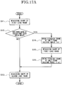
- FIG. 17A is an explanatory flow chart of a control in a case where the slide frames 3, 3 entirely are swung in the direction of an arrow D.
- FIGs. 17B and 17C are specifically explanatory views of the movement of the shape measurement apparatus for eyeglasses by the control illustrated in FIG. 17A .
- a following control is performed by the controlling-calculating circuit 52 (see FIG. 10A ) as a controlling-calculating section.
- the controlling-calculating circuit 52 controls a holder swing mechanism S comprising, the guide rail 403, the supporting rollers 406, 407, the belt 408, the motor 409, the driving roller 410 and the like, and the slide frames 3, 3 which hold the eyeglass frame are in a horizontal state (see FIG. 17B ), and a shape measurement of a first lens frame of the eyeglass frame is performed.
- a step S12 the controlling-calculating circuit 52 judges if a curve amount Wp of the eyeglass frame exceeds a certain value or not.
- the controlling-calculating circuit 52 performs a shape measurement of a second lens frame of the eyeglass frame, while maintaining the slide frames 3, 3 in the horizontal state (see FIG. 17C ).
- the controlling-calculating circuit 52 controls the holder swing mechanism S, and the slide frames 3, 3 are swung in one direction (see FIG. 17D ).
- This swing angle is set to be an amount which negates the curve amount Wp of the eyeglass frame (this is taken as a frame holding angle ( ⁇ )).
- step S 15 the shape measurement of the first lens frame in a state of being swung is performed again (see FIG. 17E ).
- the swing angle this time is stored in the memory 55 (see FIG. 10A ).
- the controlling-calculating circuit 52 controls the holder swing mechanism S and the slide frames 3, 3 are swung in an opposite direction to the one direction described above in order to perform the shape measurement of the second lens frame of the eyeglass frame (see FIG. 17F ).
- the controlling-calculating circuit 52 swings the slide frames 3, 3 based on the swing angle stored in the memory 55.
- the controlling-calculating circuit 52 swings the slide frames 3, 3 at only the frame holding angle (- ⁇ ) so that the second lens frame is in the horizontal state. And the operation of the step S13 is performed. That is, the shape measurement of the second lens frame is performed in this state.
- the frame holding angle ( ⁇ ) is stored in the memory 55, and based on the stored result, the slide frames 3, 3 are swung at only the frame holding angle (- ⁇ ), and thereby the inner circumferential contour shape measurement of the first lens frame and the inner circumferential contour shape measurement of the second lens frame are performed in which each lens frame is approximately in the horizontal state. Therefore, in a case of the shape measurement of the lens frame, an angle deviation of the tip of the measuring element for the lens frame 37 and the groove portion Ym can be small, and thereby a measurement error can be reduced.
- the shape measuring apparatus for eyeglasses not only the inner circumferential contour shape of the lens frame of the eyeglass frame but also the contour shape of the lens for eyeglasses are measured.
- the lens such as the demo lens or the like is held by the lens holder described above, and the lens holder is held between the slide frames 3, 3.
- the side plates of the lens holder disclosed in Japanese patent publication number H10-328992 are sandwiched between the holding bars 3b1 and 3b2 described above, or a flange provided at a side portion of the lens holder disclosed in Japanese patent publication number H08-294855 is sandwiched between the holding bars 3b1 and 3b2 described above.
- the lens held by the lens holder faces its convex surface downward.
- a bridge 201 is mounted between the right and left lenses Lm (MR), Lm (ML) (a space on a nose side), and attachments for temples 202, 203 are respectively mounted in an opposite side (ear side) of the right and left lenses Lm (MR), Lm (ML).
- This bridge 201 has side plate portions 201a, 201b and fixing plate portions 201c, 201d.
- the side plate portions 201a, 201b abut on the nose side of circumferential surface of the lenses Lm(MR), Lm(ML).
- the fixing plate portions 201c, 201d abut on a back surface of the lenses Lm(MR), Lm(ML).
- the attachment for the temple 202 has a side plate portion 202a and a fixing plate portion 202b.
- the side plate portion 202a abuts on an ear side of the circumferential surface of the lenses Lm(MR), Lm (ML).
- the fixing plate portion 202b abuts on the back surface of the lenses Lm (MR), Lm (ML).
- the attachment for the temple 203 has a side plate portion 203a and a fixing plate portion 203b.
- the side plate portion 203a abuts on an ear side of the circumferential surface of the lenses Lm(MR), Lm (ML).
- the fixing plate portion 203b abuts on the back surface of the lenses Lm (MR), Lm (ML).
- the mounting holes 204, 205 are formed in end portions on the nose side (end portions facing each other), and the mounting holes 206, 207 are formed in end portions on the ear side.
- a left fixing plate portion 201c of the bridge 201 is fixed to the lens Lm (ML) by a screw 204s inserted into the mounting hole 204, and a right fixing plate portion 201d of the bridge 201 is fixed to the lens Lm (MR) by a screw 205s inserted into the mounting hole 205.
- the fixing plate portion 202b of the attachment for the temple 202 is fixed to the lens Lm (ML) by a screw 206s inserted into the mounting hole 206
- the fixing plate portion 203b of the attachment for the temple 203 is fixed to the lens Lm (MR) by a screw 207s inserted into the mounting hole 207.
- the lenses Lm (ML), Lm(MR) will be explained simply as the lens Lm.
- the controlling-calculating circuit 52 When the controlling-calculating circuit 52 receives the signal transmitted from the holder detector 53, the controlling-calculating circuit 52 moves the slider 15 from the origin position along the guide rail 14 in a projection direction of the measuring element for the lens frame 37 and places the measuring element 36 outside of the circumference of the lens held by the lens holder described above.
- the controlling-calculating circuit 52 elevates the shaft 51 of the linear actuator 50 the same as described above, so that the measuring element for the lens frame 37 is elevated from the default position (A) in FIG. 7 to the height (B).
- the measuring element 36 is also elevated and the back surface 36c of the upright part 36b of the measuring element 36 is elevated to a height corresponding to the circumference of the lens held by the lens holder.
- the controlling-calculating circuit 52 performs a drive control of the motor 18, so that the slider 15 is moved to a position where the back surface 36c of the measuring element 36 abuts on a circumferential surface of the lens Lm held by the lens holder, as illustrated in FIG. 18 .
- the control described above is performed based on data of shapes of standard lenses calculated by experiments performed beforehand and the like.
- a method in which the measuring element 36 abuts on the circumferential surface of the lens Lm may be a method other than the method described above.
- the shaft 51 of the linear actuator 50 when the shaft 51 of the linear actuator 50 is elevated, the shaft 51 lifts up the free end portion of the elevation position regulating lever 49 from a position in FIG. 7 to a position in FIGs. 15 to 17 , and turns integrally the elevation position regulating lever 49 with the supporting shaft 46.
- this pressing lever 47 turns integrally with the supporting shaft 46, and the free end portion of the pressing lever 47 is elevated by a predetermined distance.
- the engaging pin 44 follows the free end portion of the pressing lever 47 and is elevated by the elastic force of the coil spring 43. Therefore, the measuring element shaft 35 is elevated by only a predetermined distance, the measuring element 36 is elevated, and the measuring element for the lens 38 of the measuring element 36 abuts on the surface of the lens Lm.
- the motor 18 is driven and controlled, the slider 15 is moved along the guide rail 14 at a predetermined speed, the measuring element 36 is moved along the surface of the lens Lm to a circumference portion side, and the measuring element 36 is moved to a position which is greatly diverged from the circumference of the surface of the lens Lm.
- the measuring element for the lens 38 is diverged from the circumference of the surface of the lens Lm and elevated by the elastic force of the coil spring 43, and accordingly the measuring element 36 entirely is elevated.
- a movement speed of the measuring element 36 in a direction along the guide rail 14 is set to be relatively small, so that it is possible to prevent a portion other than the measuring element for the lens 38 of the measuring element 36 from hitting the lens Lm.
- a position where the measuring element 36 is diverged from the surface of the lens Lm, that is, a diverging position, is detected from a drastic increase of the movement distance in the vertical direction of the measuring element 36 measured by the linear scale 40.
- a position in the horizontal direction where the measuring element 36 is at this diverging position is obtained by a signal from the linear scale 24.
- the position where the measuring element 36 is diverged from the surface of the lens Lm is obtained as data of three-dimensional coordinates by a detection signal from the linear scales 24, 40 at the diverging position.
- controlling-calculating circuit 52 performs a drive control of the linear actuator 50 based on the data of three-dimensional coordinates at this diverging position, so that a height of the free end portion of the elevation position regulating lever 49 is adjusted, a height of the free end portion of the pressing lever 47 is adjusted, and a height of the measuring element 36 is adjusted to correspond to a height of the circumference of the lens Lm held by the lens holder.
- the controlling-calculating circuit 52 performs a drive control of the motor 18 to transmit a rotation of the rotating shaft 18a of the motor 18 to the slider 15 by the wire belt 20, and controls the slider 15 to move along the guide rail 14 such that as illustrated in FIG. 18 the measuring element 36 moves until abutting on the circumferential surface of the lens Lm held by the lens holder (not illustrated).
- the measuring element 36 abuts on the circumferential surface of the lens Lm.
- the controlling-calculating circuit 52 performs a drive control of the motor 6 to rotate normally the rotating shaft 6a of the motor 6.
- a rotation of the rotating shaft 6a is transmitted to the gear 5 via the pinion 7 and the belt 8, therefore the rotating base 9 provided integrally with the gear 5 on the gear 5 rotates around a rotating shaft of the gear 5.
- a rotational angle ⁇ i measured from the reference position of the rotation is calculated based on the number of driving pulses of the motor 6 which rotates and drives the rotating base 9, and the radial coordinate ⁇ i corresponding to the rotational angle ⁇ i is obtained, and thereby the contour shape of the lens Lm is obtained in a polar coordinate system.
- a group of coordinate values expressed in the polar coordinate system ( ⁇ i, ⁇ i) is taken as information of the contour shape of the lens ( ⁇ i, ⁇ i).
- FIG. 30A there is such a two-point frame that a notch 301 (see FIG. 30B ) is provided in the circumference of the lens 300 and an attachment 305 for a temple 302 engages with this notch 301 and the temple 302 is mounted.
- a notch 301 see FIG. 30B
- a numeral 206 denotes a mounting hole for the attachment 305
- a numeral 204 denotes a mounting hole for the bridge 201 described above.
- the notch 301 described above is placed at an upper half of the lens. Therefore, concave-and-convex information by a simple measurement error and the information of the concave shape at the part corresponding to the notch 301 are distinguished by approximate information regarding an existence position of the notch 301 described above, so that a position of the notch 301 is detected from this concave position.
- a depth of the notch 301 is measured. This depth is taken as a depth Y (see FIG. 30B ).
- the depth Y of the notch 301 is measured by tracing an inner circumference of the notch 301 by the measuring element for the lens 38 in which a tip is sharp.
- the depth of the notch 301 may be inputted by an external inputting section without performing the measurement.
- a curvature of a surface fb of the lens Lm is measured by tracing the surface fb of the lens Lm by a tip of the measuring element 38, and a position Zbi in the vertical direction of the circumference of the lens Lm in the contour position of the lens ( ⁇ i, ⁇ i) is theoretically obtained from this measured curvature and the information of the two-dimensional contour shape of the lens ( ⁇ i, ⁇ i), and thereby the contour shape of the lens Lm is obtained as a group of three-dimensional coordinate values, ( ⁇ i, ⁇ i, Zbi) (coordinate values of cylindrical polar coordinates).
- this group of the coordinate values expressed in a polar coordinate system ( ⁇ i, ⁇ i, Zbi) is taken as information of the contour shape of the lens.
- a length of the circumference of the lens Lm as a demo lens is also theoretically calculated based on this information of the three-dimensional contour shape of the lens ( ⁇ i, ⁇ i, Zbi).
- a following control is performed by the controlling-calculating circuit 52 (see FIG. 10A ) as a controlling-calculating section based on a main program stored in the memory 55.
- the lens Lm is held by the lens holder (not illustrated) via the suction pad.
- the controlling-calculating circuit 52 obtains the information of the two-dimensional shape of the lens ( ⁇ i, ⁇ i) by the same procedure as the contour shape measurement of the lens Lm described above, and an operation moves to a step S2.
- the controlling-calculating circuit 52 measures the curvature of the surface fb of the lens Lm illustrated in FIG. 19 .
- the controlling-calculating circuit 52 elevates the shaft 51 of the linear actuator 50, so that a top end of the measuring element 38 is abutted on the surface fb of the lens Lm held by the lens holder described above by the elastic force of the coil spring 43.
- the lens Lm is held by the suction pad and this suction pad is detachable from the lens holder described above.
- the suction pad by which the lens Lm is held is mounted to the lens holder, so that the lens Lm is held by the lens holder.
- a center axis (optical axis) of the lens corresponds to a center axis (axis O in FIG. 7 ) of the measuring element 38 when the slider 15 is at the reference position.
- the position of the axis O is taken as an origin P0 in a radial direction of the lens Lm (this is taken as an X direction) at a curvature measurement of the surface of the lens Lm.
- the measuring element 38 when the measuring element for the lens frame 37 is descended at the default position (A), the measuring element 38 is at the lowest position, and a position of the top end (tip) of the measuring element 38 at this time is taken as a default position (C).
- This default position (C) is taken as an origin Z0 in a Z direction (vertical direction) of the measurement in FIGs. 21A and 21B .
- the controlling-calculating circuit 52 performs a drive control of the motor 18 to move the slider 15 along the guide rail 14 by the wire belt 20 which moves with this motor 18, so that the surface of the lens Lm is traced in the X direction by the tip of the measuring element 38, and the tip of the measuring element 38 is moved to measurement points P2, P1 on the surface of the lens Lm one after another.
- the measurement point P2 is a position where only a distance X2 is moved from the origin X0
- the measurement point P1 is a position where only a distance X1(X1 > X2) is moved from the origin X0.
- the controlling-calculating circuit 52 calculates and obtains positions Z2, Z1 in the Z direction of the tip of the measuring element 38 when positions in the X direction of the tip of the measuring element 38 abutting on the surface fb of the lens Lm become positions X2, X1 respectively based on a detection signal from the linear scale 40, and the operation moves to a step S3.
- the controlling-calculating circuit 52 obtains a curvature radius of the surface fb of the lens Lm and a curve value (base curve) from information of coordinate values of the measurement points P2, P1 obtained from the measurement described above.
- a distance from the origin Z0 in the Z direction to a curvature center O1 of the surface fb of the lens Lm is taken as a distance ⁇ Z
- a height measured from a height at the curvature center O1 to a height at the measurement point P2 is Z2+AZ
- a height measured from the height at the curvature center O1 to a height at the measurement point P1 is Z1 + ⁇ Z.
- coordinates of the measurement point P2 are (X2, Z2+ ⁇ Z), and coordinates of the measurement point P1 are (X1, Z1+ ⁇ Z).
- controlling-calculating circuit 52 performs a calculation to obtain a curvature from the coordinates of the measurement point P2 (X2, Z2+ ⁇ Z) and the coordinates of the measurement point P1 (X1, Z1+ ⁇ Z).
- ⁇ Z X 2 2 ⁇ X 1 2 + Z 2 2 ⁇ Z 1 2 2 Z 1 ⁇ Z 2
- the base curve of the lens for eyeglasses is set to be in a range of a base curve of 1 to a base curve of 8 as illustrated in FIGs. 22A and 22B .
- Curvature radiuses corresponding to the base curve of 1 to the base curve of 8 are described in [Table 1].
- Curve value (Base curve) Curvature radius (mm) Deviation in the Z direction Base curve obtained by an approximate curve Difference from a theoretical value 1 R1:523 ⁇ L1:0.287 1.0479465 0.0479465 2 R2:261.5 ⁇ L2:0.575 2.0183625 0.0183625 3 R3:174.3333 ⁇ L3:0.854 2.958453 -0.041547 4 R4:130.75 ⁇ L4:1.156 3.976042 -0.023958 5 R5:104.6 ⁇ L5:1.451 4.9700445 -0.0299555 6 R6:87.16667 ⁇ L6:1.75 5.977525 -0.022475 7 R7:74.71429 ⁇ L7:2.054 7.001853 0.001853 8 R8:53.75 ⁇ L8:2.365 8.0497675 0.0497675
- a curvature radius of the lens Lm as a demo lens is judged to be 523mm of R1 corresponding to a base curve of 1.
- the controlling-calculating circuit 52 obtains position information Zbi in the Z direction of the circumference of the surface fb of the lens Lm from the curvature radius (or the base curve Cv) obtained based on the deviation ⁇ L ( ⁇ L1 to ⁇ L8) in the Z direction and the contour shape information of the lens ( ⁇ i, ⁇ i), and the operation moves to a step S5.
- the controlling-calculating circuit 52 obtains three-dimensional contour shape information of the lens ( ⁇ i, ⁇ i, Zbi) from the two-dimensional contour shape information of the lens ( ⁇ i, ⁇ i) and the position information Zbi in the Z direction of the circumference of the surface fb of the lens Lm obtained in the step S4, and a length of the circumference of the lens Lm based on this three-dimensional contour shape information of the lens Lm ( ⁇ i, ⁇ i, Zbi) is calculated, and then it is finished.
- the obtained three-dimensional contour shape information of the lens ( ⁇ i, ⁇ i, Zbi) is stored in a memory 55 by the controlling-calculating circuit 52.
- the shape measuring apparatus for eyeglasses of the embodiment of the present invention performs not only the measurements of the inner circumferential contour shape of the lens frame of eyeglasses and the contour shape of the lens for eyeglasses but also a measurement of a position of the mounting hole of the lens.
- the measured three-dimensional contour shape information of the lens ( ⁇ i, ⁇ i, Zbi) in (II), (III) described above is, for example, taken as contour shape information of a lens Lm (ML) in FIG. 23B .
- the lens Lm (ML) in FIG. 23B has mounting holes 204, 206 and the lens Lm (MR) in FIG. 23B has mounting holes 205, 207.
- the controlling-calculating circuit 52 sets search areas Sa, Sb for the mounting hole to be inside a contour of the lens Lm (MR), as illustrated in FIG. 24 , based on this three-dimensional contour shape information ( ⁇ i, ⁇ i, Zbi).
- controlling-calculating circuit 52 moves the measuring element for the lens 38 in the search areas Sa, Sb for the mounting hole and detects the mounting holes 206, 204.
- the measuring element for the lens 38 is moved in the search areas Sa, Sb for the mounting hole, if the measuring element for the lens 38 comes outside of the lens Lm and the tip of the measuring element for the lens 38 is displaced from the lens Lm, it may take a time to return an abutting state of the measuring element for the lens 38 and the lens Lm to the state as they were.
- the search areas Sa, Sb for mounting hole are set to be in a predetermined area inside an outer circumference of the lens Lm (for example, 1mm inside) based on the three-dimensional contour shape information of the lens ( ⁇ i, ⁇ i, Zbi).
- the measure of 1mm is an example, and is not limited to 1mm. That is, it is preferable that the measuring element for the lens 38 be not displaced from the lens Lm and detects the mounting hole.
- the controlling-calculating circuit 52 scans (moves) in a zigzag the lens measuring element for the lens 38 in the search areas Sa, Sb for mounting hole as illustrated by arrows A1, A2 in FIG. 24B and detects mounting holes 206, 204.
- the measuring element for the lens 38 is moved in a zigzag from an upper portion to a lower portion of the lens Lm.
- the measuring element for the lens 38 may be moved in a zigzag from both right and left ends to inside of the lens Lm.
- a mechanism which slides the base 2 entirely by a pulse motor (not illustrated) is provided, and a drive of the rotating base 9 by the motor 6 and a drive of the pulse motor are controlled by the controlling-calculating circuit 52, so that a zigzag movement in the horizontal direction of the measuring element for the lens 38 as described above is performed.
- a (zigzag) movement pattern of the measuring element for lens 38 is given by a group of coordinate values ( ⁇ i', ⁇ i) as function data of the rotational angle ⁇ i of the rotation of the rotating base 9 by the motor 6 and a slide movement amount by the pulse motor, that is, a radial coordinate ⁇ '.
- the zigzag movement of the measuring element for the lens 38 may be performed by controlling a drive of the rotating base 9 by the motor 6 and a drive of the slider 15 by the motor 18 by the controlling-calculating circuit 52.
- the measuring element for the lens 38 is moved and the linear scale 40 traces a vertical movement of the measuring element 36, so that a position (height) Zi' in the vertical direction of the measuring element for the lens 38 is obtained.
- the three-dimensional position information of the measuring element for the lens 38 when the measuring element for the lens 38 is moved in a zigzag as described above is obtained as a group of coordinate values ( ⁇ i', ⁇ i, Zi') expressed in the polar coordinate system.
- the measuring element for the lens 38 moves in the vicinity of the mounting hole 206, for example, as illustrated by arrows B1, B2 in FIGs. 25A to 25C , the measuring element for the lens 38 moves smoothly upward along the surface of the lens Lm around passing the mounting hole 206, however the measuring element for the lens 38 is elevated steeply in the vicinity of a position where the mounting hole 206 is formed.
- a position Zi' of the measuring element for the lens 38 is obtained as a Zi'- ⁇ i' curve as illustrated in FIG. 25D from a detection signal of the linear scale 40.
- the position Zi' of the measuring element for the lens 38 changes smoothly upward as illustrated by the arrow B1', and when the tip of the measuring element for the lens 38 enters the mounting hole 206 at a position P, the position Zi' of the measuring element for the lens 38 changes greatly.
- the measurements of the mounting holes 204, 205, 207 are performed the same as the above.
- the above embodiment has a structure such that the bridge 201, as illustrated in FIG. 23B , has the fixing plate portions 201c, 201d which abut on the back surface of the lenses Lm (ML), Lm (MR), and the attachments for temples 202, 203, as illustrated in FIG. 23B , respectively have the fixing plate portions 202b, 203b which abut on the back surface of the lenses Lm (ML), Lm (MR), however the structure is not limited to the above embodiment.
- the variant example 1 may have a structure such that the bridge 201 has fixing plate portions 201c, 201d which abut on a front surface of the lenses Lm (ML), Lm (MR), and the attachments for temples 202, 203 respectively have fixing plate portions 202b, 203b which abut on the front surface of the lenses Lm (ML), Lm (MR).
- a curvature of the front surface and a length of the circumference of the lenses Lm (ML), Lm (MR) are measured in the same manner as the back surface of the lens Lm as described above, and positions of the mounting holes 204 to 206 are measured.
- FIGs. 26A and 26B portions which are the same or approximately the same portions in FIGs. 23A and 23B are denoted by the numerals used in the FIGs. 23A and 23B , and will not be explained.
- search areas Sa, Sb for mounting holes which extend vertically in the right and left portions of the lens Lm are set, however the search areas are not limited to the above embodiment.
- an allowance line 304 for the measurement inside a predetermined amount (for example, 1mm inside) from an outer circumferential surface of the lens Lm is set, and a search area for mounting holes Sc of a predetermined area (for example, 10mm ⁇ 10mm) is set beforehand.
- a number of measurement points Pi for example, 200 measurement points in a vertical and horizontal arrangement
- a shape of the surface of the lens Lm in the vicinity of each of the 200 measurement points Pi in the vertical and horizontal arrangement is traced by the measuring element for the lens 38, so that a position of the mounting hole is obtained from a place where the measuring element for the lens 38 is displaced upward greatly in the search area for mounting holes Sc.
- the obtained position for the mounting hole ( ⁇ i', ⁇ i, Zi') is stored as the three-dimensional position information in the memory 55, and is taken as data of the mounting hole (position data for opening a hole).
- Positions in which the mounting holes 204 to 207 and the like are provided to the shape of the lens Lm as a typical example are positions which are closer to an upper side of right and left end portions of the lens Lm, or positions which are closer to the center portion in the vertical direction of the right and left end portions of the lens Lm.
- a switch for selecting a detection position in right and left upper end portions, or a center portion in the vertical direction or the like of the lens Lm is provided, and based on the selected detection position by this switch and the contour shape information (pi, ⁇ i, Zbi) of the lens, the search area for mounting holes Sc may be set.
- a shape 220 of the lens Lm is displayed on a touch-panel type liquid crystal display monitor 221 and approximate positions of the mounting holes 204-207 and so on are indicated by a touch-panel of the liquid crystal display monitor 221, so that the indicated position, for example, the indicated position is indicated by a cross mark 222, and an area which is in the vicinity centering on this indicated position may be set as the search area for mounting holes Sc.
- FIGs. 31A and 31B are examples where a plurality of rollers are provided in a frame holder and these rollers are rolled on a guide rail, so that the frame holder is swung.
- a plurality of rollers 421 are provided in a frame holder 420 and these rollers 421 are rolled right and left on a guide rail 422 where a top surface is a concave-shape.
- the top surface of the guide rail 422 is formed in a cylinder-side-surface-like shape, and the frame holder 420 is swung in directions of arrows E1 and E2 centering around a virtual axis 423 which is in a position separated from a main body of a measuring apparatus (above the main body of the measuring apparatus).
- a numeral 424 is a measuring element which performs a shape measurement of an eyeglass frame 425 of eyeglasses.
- the eyeglass frame 425 is set in the frame holder 420 and is held at a distance R1 from the virtual axis 423.
- a plurality of rollers 431 are provided in a frame holder 430, and these rollers 431 are rolled right and left on a guide rail 432 where a top surface is a convex-shape.
- the top surface of the guide rail 432 is formed in a cylinder-side-surface-like shape, and the frame holder 430 is swung in directions of arrows F1, F2 centering on a virtual rotational axis 433 which is in a position separated from the main body of the measuring apparatus (above the main body of the measuring apparatus).
- a numeral 434 is a measuring element which performs a shape measurement of an eyeglass frame 435 of eyeglasses.
- the eyeglass frame 435 is set in the frame holder 430 and is held at a distance R1 from the virtual rotational axis 433.
- the flow chart illustrated in FIG. 17 is applicable to a case of the FIG. 31B .
- the shape measuring apparatus for eyeglasses of the embodiment of the present invention comprises a lens holder (not illustrated) which is provided in the main body of the measuring apparatus 1, a measuring element 36 which measures a circumferential shape of a lens Lm held by the lens holder, movement sections (motors 6, 18) which move the measuring element 36 along an outer circumferential surface of the lens Lm, a linear scale 24 which detects a position in a radial coordinate direction of the measuring element 36, a linear scale 40 which detects a position in a vertical direction of the linear scale 24, and a controlling-calculating circuit 52 which obtains contour shape data of a circumferential surface of the lens Lm as three-dimensional information based on a detection signal from the linear scales 24, 40.
- the shape measuring apparatus for eyeglasses of the embodiment of the present invention controls the motors 6, 18 and a tip of a measuring element 38 abuts on the surface of the lens Lm and moves, so that a relationship of a contour shape of the circumference of the lens Lm and a hole position based on a detection signal of the linear scale 40 is detected.
- the shape measuring apparatus for eyeglasses of the embodiment of the present invention detects a notch position of the lens having the notch in the circumference by the measurement of the circumferential shape of the lens.
- a notch is provided in a circumference of a lens and this notch is used for mounting of the attachment of the 2-point eyeglass frame.
- a measuring element for the lens 38 which detects a mounting hole for the lens and a measuring element for a lens frame 37 of the shape measuring apparatus for eyeglasses of the embodiment of the present invention may be structured by different members.
- a holder which is inclined to approximately 40 degrees at most is provided as a holder which holds an eyeglass frame, so that a shape of the eyeglass which exceeds a base curve of 8 is easily and precisely measured.
- the shape measuring apparatus for eyeglasses of the embodiment of the present invention accurately obtains a specific inclination angle of the holder and respectively measures inner circumferential contour shapes of lens frames in a state where each lens frame of right and left is approximately parallel to a sliding direction of the measuring element, so that accurate inner circumferential contour shapes are obtained, and thereby an accurate distance between geometric centers of each lens frame is obtained from these inner circumferential contour shapes.
Landscapes
- Physics & Mathematics (AREA)
- General Physics & Mathematics (AREA)
- A Measuring Device Byusing Mechanical Method (AREA)
- Eyeglasses (AREA)
- Grinding And Polishing Of Tertiary Curved Surfaces And Surfaces With Complex Shapes (AREA)
Description
- This invention relates to a shape measuring apparatus for eyeglasses which measures a lens shape of a lens for eyeglasses or an inner circumferential contour shape of a lens frame of eyeglasses.
- A shape measuring apparatus for eyeglasses for measuring a contour shape of a pair of lens frames comprising an eyeglass frame, for example, is disclosed in Japanese patent publication number
H07-290348 H07-285057 - The shape measuring apparatus for eyeglasses has a holder which holds an eyeglass frame, a turning section which turns the holder around a rotating shaft provided in the shape measuring apparatus for eyeglasses, a measuring element which traces a groove portion formed inside of the pair of lens frames of the eyeglass frame, a driver which drives the measuring element, a position detector which detects a position of the measuring element, and a controlling-calculating section which controls the driver and obtains and processes position information of the measuring element by the position detector.
- In the shape measuring apparatus for eyeglasses, in a state where the eyeglass frame is held by the holder, the controlling-calculating section controls the turning section such that a lens frame which is measured is in approximately a horizontal state when measuring, and controls the driver such that the measuring element slides on the groove portion of the lens frame, and thereby a three-dimensional shape of the lens frame is traced by the measuring element and the three-dimensional shape of the lens frame is obtained based on information of a driving state of the driver and position information of the measuring element by the position detector.
- However, in the above shape measuring apparatuses for eyeglasses, a turning angle by the turning section is approximately 20 degrees at most. Therefore, it is difficult to measure the shape of an eyeglass frame which is highly-curved such as wraparound eyeglasses worn by athletes, for example.
- Moreover, it is difficult for the shape measuring apparatus for eyeglasses to accurately measure a contour shape of the eyeglass frame which exceeds a base curve of 8, therefore a distance between geometric centers of each lens frame of the eyeglass frame is not obtained.
- In addition, an eyeglass frame generally has a first lens frame and a second lens frame at the right and left, and a bridge which connects the first and the second lens frames. The eyeglass frame is manufactured symmetrically centering on the center of the bridge.
- However, actual shapes and sizes of a first lens and a second lens which respectively fit in the first lens frame and the second lens frame are often slightly different from each other. If shape measuring data of one lens (for example, the first lens) is used for a fabrication of the other lens (for example, the second lens), these lenses do not often smoothly fit in the lens frames.
- In a case as described above, an adjustment by hand is needed afterward, that is, an additional fabrication is needed. In some cases where the adjustment does not work properly and so on, there is a possibility that a new fabrication is needed.
-
EP0689900 discloses an apparatus for measuring a lens frame configuration of a lens frame, suitable for use in combination with a lens grinding machine. - An object of the present invention is to provide a shape measuring apparatus for eyeglasses which easily and accurately measures a shape of an eyeglass frame which exceeds a base curve of 8.
- In order to achieve the above object, the present invention provides a shape measuring apparatus for eyeglasses according to
claim 1. - Preferably, the eyeglass element is a pair of lens frames comprising an eyeglass frame, and the measuring element traces respectively each groove portion which is formed inside of each lens frame, so that an inner circumferential contour shape of each lens frame is measured.
- Preferably, the eyeglass frame is highly-curved, and in a state where the eyeglass frame is held by the holder, a curvature center of a curve of the eyeglass frame is set to be a position which is close to the virtual rotational axis.
- Preferably, the controlling-calculating section, in a state where the holder is swung such that one lens frame of the pair of lens frames is in approximately a horizontal state, rotates the measuring element around an axis set in the apparatus which extends in a vertical direction and a groove portion of the one lens frame is traced by the measuring element.
- Preferably, in a case where a curved amount of the one lens frame of the pair of lens frames measured by the measuring element does not exceed a certain amount, after measuring an inner circumferential contour shape of the one lens frame, while maintaining the holder in a horizontal state, the controlling-calculating section measures a shape of another lens frame of the pair of lens frames, and in a case where the curved amount of one lens frame measured by the measuring element exceeds the certain amount, the controlling-calculating section sets a frame holding angle which is an angle capable of negating the curved amount of the one lens frame, and measures the shape of the one lens frame after swinging the holder at only the frame holding angle.
- Preferably, in the case where the curved amount of the one lens frame measured by the measuring element exceeds the certain amount after measuring the shape of the one lens frame, the controlling-calculating section measures a shape of the other lens frame of the pair of lens frames, in a state where the holder is swung at the same angle as the frame holding angle in an opposite direction.
- Preferably, the eyeglass element is a lens for eyeglasses.
- Preferably, the measuring element traces a circumference of the lens for eyeglasses held by the holder, so that a two-dimensional contour shape of the circumference of the lens for eyeglasses is measured.
- Preferably, the measuring element measures positions of at least two points on a surface of the lens for eyeglasses held by the holder, so that a curvature radius of the lens for eyeglasses is calculated.
- Preferably, a three-dimensional contour shape of the lens for eyeglasses is calculated by information of the measured curvature radius of the lens for eyeglasses and information of the two-dimensional contour shape of the circumference measured by tracing the circumference of the lens for eyeglasses by the measuring element.
- Preferably, a length of the circumference of the lens for eyeglasses is calculated by information of the calculated three-dimensional contour shape of the lens for eyeglasses.
- Preferably, a curve value of the lens for eyeglasses is calculated by measuring positions of at least two points on a surface of the lens for eyeglasses held by the holder by the measuring element.
- Preferably, a position of a mounting hole for the eyeglass element is measured by tracing a surface of the lens for eyeglasses held by the holder by the measuring element.
-
-
FIG. 1 is a partial schematic perspective view of a shape measuring apparatus for eyeglasses according to an embodiment of the present invention. -
FIG. 1A is a perspective view of the shape measuring apparatus for eyeglasses according to the embodiment of the present invention. -
FIG. 1B is a perspective view of the shape measuring apparatus for eyeglasses ofFIG. 1A viewed from a different view-point. -
FIG. 1C is a side view of the shape measuring apparatus for eyeglasses ofFIG. 1A viewed from a direction of an arrow C. -
FIG. 1D is a top view of the shape measuring apparatus for eyeglasses ofFIG. 1A . -
FIG. 1E illustrates a mechanism which swings a frame holder. -
FIG. 2 is a perspective view of a measuring mechanism of the shape measuring apparatus for eyeglasses ofFIG. 1 . -
FIG. 3 is a front view of the measuring mechanism ofFIG. 2 . -
FIG. 4 is a back view of the measuring mechanism ofFIG. 2 . -
FIG. 5 is a right side view of the measuring mechanism ofFIG. 4 . -
FIG. 5A is a schematic diagram illustrating a driver of a rotating base of the measuring mechanism ofFIG. 2 . -
FIG. 5B is a schematic diagram explaining a slider drive mechanism ofFIG. 2 . -
FIG. 5C is a top view ofFIG. 5B . -
FIG. 5D is a schematic explanatory view of a slide reference position detector of a slider ofFIG. 2 . -
FIG. 6 is a perspective view of a moving-up-and-down mechanism of a measuring element ofFIG. 2 . -
FIG. 7 is an explanatory view of a measurement of a lens frame by the moving-up-and-down mechanism ofFIG. 6 . -
FIG. 8 is a left side view ofFIG. 7 . -
FIG. 9 is a partially enlarged perspective view of a measuring element illustrated inFIG. 1 . -
FIG. 10 is a side view ofFIG. 9 . -
FIG. 10A is a block diagram of a controller of the shape measuring apparatus for eyeglasses illustrated inFIG. 1 . -
FIG. 11 is a perspective view explaining a function of the moving-up-and-down mechanism of the measuring element ofFIG. 6 . -
FIG. 12 is an explanatory view of a measurement of the lens frame by the moving-up-and-down mechanism ofFIG. 11 . -
FIG. 13 is an explanatory view of a linear scale of the moving-up-and-down mechanism ofFIG. 11 . -
FIG. 14 is a right side view ofFIG. 13 . -
FIG. 15 is a perspective view explaining a function of the moving-up-and-down mechanism of the measuring element ofFIG. 6 . -
FIG. 16 is an explanatory view of a measurement of the lens frame by the moving-up-and-down mechanism ofFIG. 15 . -
FIG. 17 is a left side view ofFIG. 16 . -
FIG. 17A is a flow chart illustrating an operation in a case where an inner circumferential contour shape of each lens frame of an eyeglass frame is measured. -
FIG. 17B specifically illustrates a movement by an operation ofFIG. 17A and illustrates a manner where a first lens frame is measured in a case where the eyeglass frame is in a horizontal state. -
FIG. 17C specifically illustrates a movement by an operation ofFIG. 17A and illustrates a manner where a second lens frame is measured where the eyeglass frame is in a horizontal state. -
FIG. 17D illustrates a sequel movement ofFIG. 17B and illustrates a manner where the eyeglass frame is swung at only a frame holding angle (α). -
FIG. 17E illustrates a sequel movement ofFIG. 17B and illustrates a manner where the first lens frame is measured. -
FIG. 17F illustrates a sequel movement ofFIG. 17B and illustrates a manner where the eyeglass frame is swung at only a frame holding angle (-α). -
FIG. 18 is a movement explanatory view of a moving-up-and-down mechanism ofFIG. 2 . -
FIG. 19 is a movement explanatory view of the moving-up-and-down mechanism ofFIG. 2 . -
FIG. 20 is a flow chart for obtaining contour shape information and a length of a circumference of a lens by the shape measuring apparatus for eyeglasses ofFIGs. 1 to 5 . -
FIG. 21A is an explanatory view regarding a curvature measurement of a lens by the shape measuring apparatus for eyeglasses ofFIGs. 1 to 5 . -
FIG. 21B is a partially enlarged view ofFIG. 21A . -
FIG. 22A is an explanatory view of a curve value (base curve) of a lens for eyeglasses. -
FIG. 22B is a characteristic line which illustrates a relationship of the curve value ofFIG. 22A and a difference of Z coordinates between 2 measurement points on a surface of a lens. -
FIG. 23A is a perspective view of an example of 2-point lens frame eyeglasses. -
FIG. 23B is a cross-sectional view ofFIG. 23A taken along a line C1-C1. -
FIG. 24A is an explanatory view of an example of a position detecting area of a mounting hole of the lens. -
FIG. 24B is a function explanatory view of a position detection of the mounting hole. -
FIG. 24C is a function explanatory view of the position detection of the mounting hole. -
FIG. 25A is a partial cross-sectional view explaining a detection of the mounting hole provided in the lens. -
FIG. 25B is a partial cross-sectional view explaining the detection of the mounting hole provided in the lens. -
FIG. 25C is a partial cross-sectional view explaining the detection of the mounting hole provided in the lens. -
FIG. 25D is an explanatory view explaining the detection of the mounting hole ofFIGs. 25A to 25C . -
FIG. 26A is a perspective view illustrating another example of 2-point lens frame eyeglasses. -
FIG. 26B is a cross-sectional view ofFIG. 26A taken along a line D1-D1. -
FIG. 27 is an explanatory view illustrating another example of the position detection area of the mounting hole of the lens and the lens frame. -
FIG. 28 is an explanatory view illustrating an example of a position of the position detection in the position detection area of the mounting hole of the lens ofFIG. 27 . -
FIG. 29 is an explanatory view of a liquid crystal display used by setting the position detection area of a mounting hole of the lens. -
FIG. 30A is an explanatory view of a variant example. -
FIG. 30B is an explanatory view of a variant example. -
FIG. 31A is a view which illustrates that a frame holder is provided with a plurality of rollers and the frame holder is swung by a rolling movement of the rollers on a guide rail, and illustrates a case where a top surface of the guide rail is concave-shape. -
FIG. 31B is a view which illustrates that a frame holder is provided with a plurality of rollers and the frame holder is swung by a rolling movement of the rollers on a guide rail, and illustrates a case where a top surface of the guide rail is convex-shape. - Hereinafter, an embodiment of the present invention will be explained based on the drawings.
-
FIG. 1 illustrates a structure of a chief part of a shape measuring apparatus for eyeglasses according to the embodiment of the present invention. - The shape measuring apparatus for eyeglasses has a
main body 1 of the measuring apparatus. - The
main body 1 of the measuring apparatus has acase portion 1a for storing a measuring mechanism provided in a lower part, and a lensframe holding mechanism 1b provided in an upper part of thecase portion 1a. At a bottom part in thecase portion 1a ofFIG. 1 , abase 2 illustrated inFIG. 2 is provided. - As described in
FIG. 1 , the lensframe holding mechanism 1b has a pair ofparallel guide rods case portion 1a. - In the
guide rods - The slide frames 3, 3 are urged by a coil spring or the like (not illustrated) in a direction of moving close to each other. The slide frames 3, 3 have
vertical plates lens frame holder 3b which holds the eyeglass frame on thevertical plates - In the
lens frame holder 3b, two pairs of four pairs of holding bars 3b1, 3b2 are respectively provided on thevertical plates - Each holding bar 3b1, 3b2 projects from the
vertical plates vertical plates - A structure which Japanese patent publication number
H10-328992 frame holding mechanism 1b as described above. Therefore, the lensframe holding mechanism 1b will not be explained in detail. -
FIG. 1A is a perspective view of the shape measuring apparatus for eyeglasses according to the embodiment of the present invention.FIG. 1B is a perspective view of the shape measuring apparatus for eyeglasses ofFIG. 1A viewed from a different view point. -
FIG. 1C is a side view of the shape measuring apparatus for eyeglasses viewed from a direction of an arrow C, andFIG. 1D is a top view of the shape measuring apparatus for eyeglasses. - The slide frames 3, 3, as described in
FIGs 1A to 1C , have abottom surface 400 which is a downwardly convex-shape, and in which a shape of a lower surface is polygonal. - In the
bottom surface 400, anopening 400A is formed in the center. - A measuring
element 36 is inserted upwardly in theopening 400A from a lower side toward an upper side. - The measuring
element 36 will be explained later. - The
bottom surface 400 may be a cylindrical surface which is a downwardly rounded-convex-shape. - On both end surfaces 401, 401 outside of the slide frames 3, 3 of the
case portion 1a,guide rails rotational axis 402, are mounted. - On the other hand, in the
main body 1 of the measuring apparatus, acover 404 for a lower case is provided, at both sides of an upper part of thecover 404,brackets - At each
bracket 405, supportingrollers 406 are respectively provided at an upper part of eachbracket 405, and supportingrollers 407 are respectively provided below the supportingrollers 406. Each supportingroller - Each supporting
roller bracket 405 is arranged to sandwich theguide rail 403 of theslide frame 3 between the supportingrollers guide rail 403. - That is, both slide frames 3, 3 are supported on the
cover 404 of themain body 1 of the measuring apparatus. - Therefore, both slide frames 3, 3 are capable of swinging centering on the virtual
rotational axis 402 in a direction of an arrow D. - As described in
FIG. 1E , abelt 408 is abutted on a lower end surface of theguide rail 403. - Both end portions of the
belt 408 are fixed to both end portions of theguide rail 403, and the remaining portion of the belt 408 (a portion except the both end portions of the belt 408) is not fixed to theguide rail 403. - That is, the remaining portion of the
belt 408 is capable of being spaced from the lower end surface of theguide rail 403. - At the
brackets rollers cover 404 for a lower case, a motor 409 (seeFIGs. 1A to 1D ) is provided as a driver. - A driving
roller 410 is mounted at a rotating shaft of themotor 409. - The driving
roller 410 is placed in approximately a middle of the supportingrollers rollers - The
belt 408 fixed to the both end portions of theguide rail 403 is wound on the drivingroller 410 via the supportingrollers - An upper surface (a surface in contact with the lower end surface of the guide rail 403) of the
belt 408 is gear-like, and an outer circumferential surface of the drivingroller 410 is also gear-like. Therefore, a friction coefficient between the upper surface of thebelt 408 and the outer circumferential surface of the drivingroller 410 is large. - Therefore the
belt 408 does not slip on the drivingroller 410, and rotating the drivingroller 410 makes it possible to move theguide rail 403 in a right direction or in a left direction inFIG. 1E . As a result, theslide frame 3 of the lensframe holding mechanism 1b is capable of swinging centering on the virtualrotational axis 402 in the direction of the arrow D (seeFIGs. 1A and1C ). - In the
main body 1 of the measuring apparatus, a swing angle detector which detects an angle (a swing angle) when theslide frame 3 swings is provided, which is not illustrated. - A holder swing mechanism S comprises these
guide rails 403, the supportingrollers belt 408, themotor 409, and the drivingroller 410. - A
measuring mechanism 1d as described inFIGs. 2 to 5 is provided on thebase 2. - The
measuring mechanism 1d has abase supporting member 4 which is fixed on thebase 2. - A
gear 5 having a large diameter is mounted rotatably around a rotating shaft C (a shaft extending in a vertical direction) which extends in a vertical direction of thegear 5 in thebase supporting member 4. - As schematically illustrated in
FIG. 5A , amotor 6 is mounted adjacent to thegear 5 on thebase 2. - A
pinion 7 is fixed to arotating shaft 6a of themotor 6, and abelt 8 is wound on thepinion 7 and thegear 5. - When the
motor 6 works, a rotation of therotating shaft 6a of themotor 6 is transmitted to thegear 5 via thepinion 7 and thebelt 8, and thereby thegear 5 rotates. - A two-phase stepping motor is used as the
motor 6. - As illustrated in
FIG.s 2 to 5 , a rotatingbase 9 is integrally fixed in an upper part of thegear 5. - In the shape measuring apparatus for eyeglasses of the embodiment of the present invention, a rotation reference position detector which detects a reference position regarding a rotation of the
rotating base 9 to thebase 2 is provided. - The rotation reference position detector comprises a light-emitting
marker 9b and aphoto sensor section 9a for indicating a reference position, and the light-emittingmarker 9b is provided on thebase 2 and thephoto sensor section 9a is provided on the rotatingbase 9. - The light-emitting
marker 9b emits light upward through a slit or a circular hole provided on thebase 2, and this light is detected by thephoto sensor section 9a fixed on the rotatingbase 9, and thereby the reference position of the rotation of therotating base 9 is detected. - In addition, well-known techniques such as a transparent type photo sensor, or a reflection type photo sensor, or a proximity sensor or the like is adoptable as the rotation reference position detector.
- Moreover, as illustrated in
FIGs 2 to 4 , at both end portions of therotating base 9,rail mounting plates rail mounting plates - As illustrated in
FIG. 3 , both end portions in a longitudinal direction of aside plate 12 are respectively fixed to one side portion of therail mounting plate 10 and one side portion of therail mounting plate 11, and as illustrated inFIG. 4 , both end portions in the longitudinal direction of aside plate 13 are respectively fixed to the other side portion of therail mounting plate 10 and the other side portion of therail mounting plate 11. - As illustrated in
FIGs. 2 to 4 , a pair of bar-shape guide rails rail mounting plates rail mounting plates - A
slider 15 is held to be slidable in a longitudinal direction on the guide rails 14, 14. - Additionally, as illustrated in
FIGs. 2 and3 , a pulley supportingplate part 12a is integrally formed at an end portion of a side of therail mounting plate 10 of theside plate 12, and abracket 16 for mounting a motor is integrally formed at an end portion of a side of therail mounting plate 11 of theside plate 12. - A
pulley 17 is mounted rotatably in a rotating shaft which extends in a vertical direction in the pulley supportingplate part 12a, and an upper end portion of amotor 18 for a movement of the slider is fixed under thebracket 16. Arotating shaft 18a of thismotor 18 extends upward, apulley 19 is mounted at therotating shaft 18a as illustrated inFIG.s. 5B and 5C . A DC motor is used as themotor 18. - As illustrated in
FIGs. 2 ,5B, and 5C , awire belt 20 is wound on thesepulleys wire belt 20 comprises awire 20A, acoil spring 23 to strain this wire, and a cylindrical-shapewire holding member 21 to hold thewire 20A bybrackets 22, 22' fixed to theslider 15. - The
wire holding member 21, in a state where the wire is inserted into an opening portion of thewire holding member 21, is fixed to thewire 20A, and both end portions of thewire 20A are connected by thecoil spring 23, so that thewire belt 20 is annular. - The
wire holding member 21 is sandwiched by thebrackets 22, 22' of theslider 15, so that thewire belt 20 is fixed to theslider 15. - Therefore, if the
motor 18 is rotated normally or reversely, therotating shaft 18a and thepulley 19 are rotated normally or reversely, theslider 15 moves in a left or a right direction inFIG. 3 . - As illustrated in
FIG. 5D , in the shape measuring apparatus for eyeglasses of the embodiment of the present invention, a slide reference position detector 20a to detect a reference position of a movement position of theslider 15 to therotating base 9 is provided. - The slide reference position detector 20a comprises a reflection plate 20b provided with a reflection surface which extends vertically (not illustrated) and a reflection
type photo sensor 20c provided integrally with a light-emitting element and a light-receiving element. The reflection plate 20b is provided in the bracket 22' and the reflectiontype photo sensor 20c is provided in theside plate 12. - Well-known techniques such as a transparent type photo sensor, a proximity sensor and the like are adoptable as the slide reference position detector 20a.
- As illustrated in
FIG. 4 , between theside plate 13 and theslider 15, a linear scale 24 (position detector) to detect a radial coordinate (a distance in a radial direction) is interposed. Thelinear scale 24 has a lengthymain scale 25, and a detection head forposition information 26 which moves along themain scale 25 and reads position information stored in themain scale 25. Themain scale 25 is fixed parallel to theguide rail 14 on theslider 15, and the detection head forposition information 26 is fixed on the supportingplate part 13a which is integrally formed on theside plate 13. - The detection head for
position information 26 detects movement information in the horizontal direction of theslider 15 from the position information stored in themain scale 25. Well-known magnetic types and optical types of linear scales, for example, are used for thislinear scale 24. - For example, in a magnetic type
linear scale 24, a magnetic pattern where magnetic poles are repeated S, N repeats alternately along its longitudinal direction at small intervals is formed in themain scale 25, and the magnetic pattern is detected by the detection head forposition information 26, so that a movement position of theslider 15 is detected from a signal as information for a position detection of a radial coordinate outputted from the detection head forposition information 26. - And in an optical type
linear scale 24, a number of slits are provided in a plate-shapemain scale 25 along its longitudinal direction at small intervals, and in a detection head forposition information 26, a light-emitting element and a light-receiving element are provided to sandwich themain scale 25 from both sides. And light emitted from the light-emitting element is detected by the light-receiving element via the slits of themain scale 25, and the number of slits are counted so that the movement position of theslider 15 is detected. - In approximately a center portion of the
slider 15, a through-hole 15a as illustrated inFIG. 2 is formed. Aguide cylinder 27 which extends vertically is inserted into the through-hole 15a. Below theslider 15, as illustrated inFIG. 4 , a supportingframe 28 is arranged. The supportingframe 28 has ahorizontal plate 31, andvertical frames horizontal plate 31, and upper end portions of thevertical frames slider 15. - As illustrated in
FIG. 6 , a pair of cylindrical-shape supporting members horizontal plate 31. - On upper end portions of the supporting
members member 33 is fixed. - A
vertical plate 34a in which a side surface is L-shape of aguide supporting member 34 is fixed on the connectingmember 33. - A lower end portion of the
guide cylinder 27 is fixed on ahorizontal plate 34b. - Inside the
guide cylinder 27, a measuringelement shaft 35 which extends vertically (long) is inserted and is fitted and held and capable of up-and-down motion freely, and a measuringelement 36 is integrally provided on an upper end portion of the measuringelement shaft 35. - As illustrated in
FIG. 10 , this measuringelement 36 has anupright part 36b which extends vertically (long), a measuring element for alens frame 37 which is fixed on the upper end portion of theupright part 36b and extends in a horizontal direction, and a measuring element for alens 38 which is fixed on the upper end portion of theupright part 36b and extends upward further from theupright part 36b. - A lower end portion of the measuring
element 36 and an upper end portion of the measuringelement shaft 35 are connected by the connectingmember 36a. - The measuring
element shaft 35, the connectingmember 36a, and the measuringelement 36 connected by the connectingmember 36a are entirely formed to be in a crank-shape. - The measuring element for the
lens frame 37 faces to the same side as the measuringelement shaft 35 of theupright part 36b, and in a part of an opposite side to the measuringelement shaft 35 of theupright part 36b, aback surface 36c which is curved with a certain curvature radius is formed. A part of thisback surface 36c is abutted on a circumference of the lens to be slid on the circumference of the lens, in a case of measuring a contour shape of the lens. - An upper portion of the measuring element for the
lens 38 is formed in a hemisphere-shape. - If the upper portion is a
hemisphere 38b, it is preferable that the curvature radius of thehemisphere 38b (that is, a radius of ashaft part 38a) be larger than a radius of a general mounting hole (a diameter is 2.2 ϕ) in order to correspond to various mounting holes. - It is not necessary for the measuring element for the
lens 38 to be provided integrally with the measuringelement 36 as described above. - For example, as illustrated in
FIG. 9 , a screw hole is provided in an upper end portion of theupright part 36b, ascrew part 36s is provided in a lower end portion of the measuring element for thelens 38, and thescrew part 36s is screwed into the upper end portion of theupright part 36b, so that the measuring element for thelens 38 may be detachable from the upper end portion of theupright part 36b. - As illustrated in
FIGs. 6 to 8 , abracket 39 is provided below the measuringelement shaft 35 and is fixed in a lower end portion of the measuringelement shaft 35. As illustrated inFIG. 13 , between thebracket 39 and theguide supporting member 34, a linear scale 40 (position detector) for detecting a height of the measuringelement 36 is interposed. - This
linear scale 40 has a stick-shapemain scale 41, and a detection head forposition information 42 which moves along themain scale 41 and reads position information of themain scale 41. - The detection head for
position information 42 is fixed to the connectingmember 33, and a lower end portion of themain scale 41 is fixed to thebracket 39 and themain scale 41 is arranged parallel to the measuringelement shaft 35 along a vertical direction. - An upper end portion of the
main scale 41 is not fixed, and this upper edge portion is inserted into holes provided in the connectingmember 33 and thehorizontal plate 34b of theguide supporting member 34, and themain scale 41 is capable of up-and-down motion freely. - In this
linear scale 40, a movement amount of themain scale 41 is detected by the detection head forposition information 42, so that a movement amount in the vertical direction of the measuringelement 36 fixed to themain scale 41 in the vertical direction via thebracket 39 is detected. A magnetic type or an optical type linear scale which is the same as thelinear scale 24 as described above is also adopted in thislinear scale 40. - In addition, as illustrated in
FIGs. 6 to 8 , between thebracket 39 and thehorizontal plate 31, acoil spring 43 is interposed and always urges the measuringelement shaft 35 upward. - In the vicinity of a joining part with the
bracket 39 of the measuringelement shaft 35, an engagingpin 44 is inserted perpendicularly into the measuringelement shaft 35 and is fixed. - As illustrated in
FIG. 6 , on thehorizontal plate 31, abracket 45 which is formed in a U-shape is fixed, and thebracket 45 has facingplates plates shaft 46 are rotatably held. Apressing lever 47 and an elevationposition regulating lever 49 are fixed to this supportingshaft 46, and thesepressing lever 47 and the elevationposition regulating lever 49 extend in the same direction to the supportingshaft 46. Therefore, the pressinglever 47 and the elevationposition regulating lever 49 take the supportingshaft 46 as a rotational axis and are rotatable to thebracket 45 fixed on thehorizontal plate 31. - Additionally, between the
pressing lever 47 and thehorizontal plate 31, acoil spring 48 is interposed, and an elastic force in a compressing direction of thiscoil spring 48 is set to be larger than an elastic force in an extending direction of thecoil spring 43 so that thecoil spring 48 always adds a force in a pulling-down direction to thepressing lever 47. Thepressing lever 47 abuts on an upper portion of the engagingpin 44 from above, and thereby an elevation of the measuringelement shaft 35 by thecoil spring 43 is regulated. - Below the elevation
position regulating lever 49, alinear actuator 50 is provided. Thelinear actuator 50 has amotor part 50a of a body of the actuator fixed on thehorizontal plate 31 and ashaft 51 which projects upward from themotor 50a and is provided parallel to the measuringelement shaft 35. - A pulse motor is used for the
linear actuator 50. By rotating theshaft 51 of thelinear actuator 50 in a normal rotation, theshaft 51 moves upward. By rotating theshaft 51 of thelinear actuator 50 in a reverse rotation, theshaft 51 moves downward. Themotor part 50a is capable of driving by a control of a controlling-calculatingcircuit 52 which is described later. Since the upper end portion of theshaft 51 of thelinear actuator 50 which moves up and down abuts on the elevationposition regulating lever 49 from below, when theshaft 51 is elevated, the pressinglever 47 is elevated with an elevation of theshaft 51, and regulating of the elevation of the measuringelement shaft 35 by the pressinglever 47 is released. - Thus, an up-and-down movement mechanism of the measuring
element 36 is structured by thecoil spring 43, the supportingshaft 46, the pressinglever 47, thecoil spring 48, the elevationposition regulating lever 49, thelinear actuator 50 and the like. - In
FIG. 10A , a numeral 52 is a controlling-calculating circuit (controlling-calculating section). - A detection signal which indicates a rotation reference position from the
photo sensor section 9a, a detection signal which indicates a slide reference position from the reflectiontype photo sensor 20c, a detection signal which indicates a radial coordinate position from the detection head forposition information 26 of thelinear scale 24, and a detection signal which indicates a height position from the detection head forposition information 42 of thelinear scale 40 are transmitted to the controlling-calculating circuit (controlling-calculating section) 52. - The controlling-calculating circuit (controlling-calculating section) 52 performs a drive control of
motors linear actuator 50. - As illustrated in
FIG. 1 , on one of side plates of the slide frames 3, 3, aholder detector 53 is provided. - The
holder detector 53 detects if a lens holder attaches to the slide frames 3, 3, which is described later, or not. - A micro switch or the like is used for the
holder detector 53. - As illustrated in
FIG. 10A , a detection signal from theholder detector 53 which indicates a mounting of the lens holder is transmitted to the controlling-calculatingcircuit 52. - Additionally, in
FIG. 10A , a numeral 54 is a start switch for starting a measurement, and a numeral 55 is a memory. Thestart switch 54 and thememory 55 are connected to the controlling-calculatingcircuit 52. - Hereinafter, a function of the shape measuring apparatus for eyeglasses will be explained.
- Before a shape measurement of a lens frame of eyeglasses or a shape measurement of a lens such as a demo-lens or the like is started by the shape measuring apparatus for eyeglasses, as illustrated in
FIGs. 6 to 8 , theshaft 51 of thelinear actuator 50 is at the lowest position. - In a case where the
shaft 51 is at the lowest position, the measuringelement shaft 35 is pressed down by the pressinglever 47. - Therefore, before the measurement is started by the shape measuring apparatus for eyeglasses, the measuring
element 36 is at the lowest position. - As illustrated in
FIG. 7 , in a case where a shape measurement of a lens frame LF (RF) of an eyeglass frame MF is performed, for example, by the same method as Japanese patent publication numberH10-328992 FIG. 1 (the eyeglass frame MF is not illustrated inFIG. 1 ), and the lens frames LF (RF) are sandwiched between the holding bars 3b1, 3b2 as illustrated inFIG. 7 . - Before the measurement begins, the lens frames LF (RF) held between the holding bars 3b1, 3b2 are set to be placed higher than the measuring element for the
lens frame 37. - That is, the measuring element for the
lens frame 37 is placed at a height of a default position (A) which is lower than the lens frames LF (RF). - In addition, the measuring
element 36 is placed at approximately a center of a default position (i) in front view of one of the lens frames LF, RF. - In a state before beginning of the measurement, it is set to become a state where the
linear scale 24 is detecting a slide reference position of theslider 15 at the same time as a state where the rotation reference position detector described above is detecting a rotation reference position of therotating base 9. - Additionally, if the lens frames are curved-shape, the holding bars 3b1, 3b2 hold a part which is at the lowest position of the lens frames.
- The shape measuring apparatus for eyeglasses of the embodiment of the present invention is configured to start a measurement of a groove position from a groove portion Ym which is at the lowest position of the lens frames LF (RF) in this
lens frame holder 3b. - This starting position of the lens frame measurement is taken as a starting position of a shape measurement B.
- In a state where the measuring
element 36 is at the default position (i), when thestart switch 54 is turned on, the controlling-calculatingcircuit 52 rotates theshaft 51 of thelinear actuator 50 in the normal rotation, and from a position illustrated inFIGs. 6 to 8 to a position illustrated inFIGs. 11 to 14 , elevates theshaft 51 by only a predetermined distance. - In this case, the
shaft 51 lifts up a free end portion of the elevationposition regulating lever 49 by only a predetermined distance against the elastic force of thecoil spring 48, and integrally turns the elevationposition regulating lever 49 with the supportingshaft 46. - With the movement described above, the pressing
lever 47 also integrally turns with the supportingshaft 46, and the free end portion is elevated by only a predetermined distance. - By the elevation of the free end portion of the
pressing lever 47, the engagingpin 44 follows the free end portion of thepressing lever 47 and is elevated by the elastic force of thecoil spring 43, so that the measuringelement 36 is elevated by only a predetermined distance. - The elevated distance of the measuring
element 36, as illustrated inFIG. 7 , is set to be a distance L in which a tip of the measuring element for thelens frame 37 is elevated from the default position (A) to a height (B) of the starting position of the shape measurement B described above. - Next, the controlling-calculating
circuit 52 performs a drive control of themotor 18, and thepulley 19 is rotated, so that theslider 15 is moved along theguide rail 14 by thewire belt 20 ofFIGs. 2 and5B . - In this case, the
slider 15 moves in the direction of an arrow A1 ofFIG. 7 . By the movement of theslider 15, the tip of the measuring element for thelens frame 37, as illustrated inFIG. 12 , abuts on the groove portion Ym at the starting position of the shape measurement B. - As described later, in a case where the tip of the measuring element for the
lens frame 37 traces along the groove portion Ym when measuring, the tip of the measuring element for thelens frame 37 is always pressed by the groove portion Ym by an action of the elastic force of thecoil spring 23. And in this state, themotor 18 is stopped by the controlling-calculatingcircuit 52. - When the tip of the measuring element for the
lens frame 37 abuts on the groove portion Ym, a load which themotor 18 receives increases, and an electric current flowing into themotor 18 increases, therefore, by detecting this change of the electric current, the controlling-calculatingcircuit 52 detects that the tip of the measuring element for thelens frame 37 abuts on the groove Ym so that themotor 18 is stopped. - Next, the controlling-calculating
circuit 52 further rotates theshaft 51 of thelinear actuator 50 in the normal rotation and elevates theshaft 51 by only a predetermined distance from a position illustrated inFIGs. 11 to 14 to a position illustrated inFIGs. 15 to 17 . - In this case, the
shaft 51 lifts up the free end portion of the elevationposition regulating lever 49 by only a predetermined distance against the elastic force of thecoil spring 48, and integrally turns the elevationposition regulating lever 49 with the supportingshaft 46. - With this movement described above, the pressing
lever 47 also integrally turns with the supportingshaft 46, and the free end portion is elevated by only a predetermined distance. - By the elevation of the free end portion of the
pressing lever 47, the pressinglever 47 moves away from the engagingpin 44 by only a predetermined distance. Therefore, the tip of the measuring element for thelens frame 37 traces along the groove portion Ym, and accordingly the measuringelement shaft 35 is capable of an up-and-down motion. - Next, if the controlling-calculating
circuit 52 performs a drive control of themotor 6 and therotating shaft 6a of themotor 6 is rotated in the normal rotation, a rotation of therotating shaft 6a is transmitted to thegear 5 via thepinion 7 and thebelt 8, so that the rotatingbase 9 which is integrally provided with thegear 5 on thegear 5 rotates around a rotating shaft of the gear 5 (seeFIG. 5A ). - When the controlling-calculating
circuit 52 performs a drive control of theslider 15 such that the tip of the measuring element for thelens frame 37 always presses the groove portion Ym, and rotates a rotated part at an upper portion of themeasuring mechanism 1d, the tip of the measuring element for thelens frame 37 moves up and down along the groove Ym and traces the groove Ym. - In this case, the
slider 15 is moved integrally with the measuring element for thelens frame 37 along theguide rail 14, therefore a movement amount from the origin position of theslider 15 becomes the same as the movement amount of the tip of the measuring element for thelens frame 37. - This movement amount is calculated by the controlling-calculating
circuit 52 based on a signal outputted from the detection head forposition information 26 of thelinear scale 24. - Since a length from a position of a center axis of the measuring
element shaft 35 to the tip of the measuring element for thelens frame 37 is known, by setting this length to the shape measuring apparatus for eyeglasses beforehand, this length is added to the movement amount from the origin position of the slider 15 (the rotational center of the rotating base 9) detected by the detection head forposition information 26, so that a radial coordinate ρi from the rotational center of therotating base 9 to the tip of the measuring element for thelens frame 37 is calculated by the controlling-calculatingcircuit 52. - Additionally, if a rotational angle of the
rotating base 9 which is measured from the reference position of the rotation described above is taken as a rotational angle θi, this rotational angle θi is calculated based on the number of driving pulses of the motor 6 (information of a driving state of the driver) which rotates and drives the rotatingbase 9. - With rotating the
rotating base 9, the radial coordinate ρi corresponding to the rotational angle θi is measured, so that an inner circumferential contour shape of the groove portion Ym of the lens frame LF (RF) (this shape is approximately a shape of the lens frame LF (RF)) is obtained in a two-dimensional polar coordinate system. - In the shape measuring apparatus for eyeglasses of the embodiment of the present invention, a group of coordinate values (ρi, θi) expressed in the polar coordinate system is taken as information of the inner circumferential contour shape of the lens frame.
- By the way, in a case where the lens frame LF (RF) is curved in the vertical direction, when the tip of the measuring element for the
lens frame 37 traces along the groove portion Ym, a displacement amount in the vertical direction by this curve in the vertical direction is obtained as the movement amount in the vertical direction of the measuring element for thelens frame 37. - In particular, this movement amount in the vertical direction, in a case where the measuring element for the
lens frame 37 traces, is calculated by the controlling-calculatingcircuit 52 based on a signal outputted by the detection head forposition information 42 of thelinear scale 40. - In the shape measuring apparatus for eyeglasses of the embodiment of the present invention, the displacement amount of the measuring element for the
lens frame 37 in the vertical direction measured from the origin position, that is, a position (height) in the vertical direction is taken as a position Zi. - Therefore, information of the inner circumferential contour shape of the groove portion Ym of the lens frame LF (RF), that is, information of the contour shape of the groove portion Ym of the lens frame LF (RF) is finally obtained as a group of three-dimensional coordinate values (coordinate values of cylindrical polar coordinates), (ρi, θi, Zi).
- This obtained three-dimensional information of the inner circumferential contour shape of the lens frame (ρi, θi, Zi) is stored in the
memory 55 by the controlling-calculatingcircuit 52. - In the shape measuring apparatus for eyeglasses according to the embodiment, in a case of a measurement of the inner circumferential contour shape, a drive control of a
motor 409 is performed, so that a drivingroller 410 illustrated inFIG. 1E is rotated normally or reversely and abelt 408 wound around the drivingroller 410 is moved in the right direction or in the left direction inFIG. 1E . And thereby, as illustrated inFIG. 2 , the slide frames 3, 3 entirely are slidable in a direction indicated by the arrow D, centering on the virtual rotational axis 402 (center of the curvature of a guide rail 403). - In addition, in the shape measuring apparatus for eyeglasses according to the embodiment, for example, even if in a case where an inner circumferential contour shape of the lens frame of eyeglass frame which exceeds a base curve of 8 is measured, in a state where the eyeglass frame is held by the slide frames 3, 3 by the lens
frame holding mechanism 1b, the curvature center of the eyeglass frame is set to be a position close to a virtualrotational axis 402. Moreover, a drive control of the slide frames 3, 3 entirely is performed such that a part of the eyeglass frame which is traced is held to be in approximately a horizontal state, therefore the tip of the measuring element for thelens frame 37 is precisely engaged with the groove portion Ym, and an accurate shape of the lens frame of eyeglasses is measured. - In addition, the tip of the measuring element for the
lens frame 37 traces a deepest part of the groove portion Ym, therefore it prevents the tip of the measuring element for thelens frame 37 from slipping from the groove Ym. And the tip of the measuring element for thelens frame 37 always traces the deepest part of the groove portion Ym, so that the inner circumferential contour shape of lens frame is precisely measured, and thereby a measurement of a distance between centers of each lens frame of the eyeglass frame, that is, a measurement of a frame PD is precisely performed. -
FIG. 17A is an explanatory flow chart of a control in a case where the slide frames 3, 3 entirely are swung in the direction of an arrow D. -
FIGs. 17B and 17C are specifically explanatory views of the movement of the shape measurement apparatus for eyeglasses by the control illustrated inFIG. 17A . - A following control is performed by the controlling-calculating circuit 52 (see
FIG. 10A ) as a controlling-calculating section. - Firstly, in a step S11, the controlling-calculating
circuit 52 controls a holder swing mechanism S comprising, theguide rail 403, the supportingrollers belt 408, themotor 409, the drivingroller 410 and the like, and the slide frames 3, 3 which hold the eyeglass frame are in a horizontal state (seeFIG. 17B ), and a shape measurement of a first lens frame of the eyeglass frame is performed. - In a step S12, the controlling-calculating
circuit 52 judges if a curve amount Wp of the eyeglass frame exceeds a certain value or not. - In a case where the curve amount Wp of the eyeglass frame does not exceed the certain value, an operation of a step S13 is performed, and in a case where the curve amount Wp of the eyeglass frame exceeds the certain value, an operation of a step S14 is performed.
- In the step S13, the controlling-calculating
circuit 52 performs a shape measurement of a second lens frame of the eyeglass frame, while maintaining the slide frames 3, 3 in the horizontal state (seeFIG. 17C ). - In the step S14, the controlling-calculating
circuit 52 controls the holder swing mechanism S, and the slide frames 3, 3 are swung in one direction (seeFIG. 17D ). This swing angle is set to be an amount which negates the curve amount Wp of the eyeglass frame (this is taken as a frame holding angle (α)). - And in a
step S 15, the shape measurement of the first lens frame in a state of being swung is performed again (seeFIG. 17E ). The swing angle this time is stored in the memory 55 (seeFIG. 10A ). - Next, in a step S16, the controlling-calculating
circuit 52 controls the holder swing mechanism S and the slide frames 3, 3 are swung in an opposite direction to the one direction described above in order to perform the shape measurement of the second lens frame of the eyeglass frame (seeFIG. 17F ). - In this case, the controlling-calculating
circuit 52 swings the slide frames 3, 3 based on the swing angle stored in thememory 55. - That is, the controlling-calculating
circuit 52 swings the slide frames 3, 3 at only the frame holding angle (-α) so that the second lens frame is in the horizontal state. And the operation of the step S13 is performed. That is, the shape measurement of the second lens frame is performed in this state. - As described above, the frame holding angle (α) is stored in the
memory 55, and based on the stored result, the slide frames 3, 3 are swung at only the frame holding angle (-α), and thereby the inner circumferential contour shape measurement of the first lens frame and the inner circumferential contour shape measurement of the second lens frame are performed in which each lens frame is approximately in the horizontal state. Therefore, in a case of the shape measurement of the lens frame, an angle deviation of the tip of the measuring element for thelens frame 37 and the groove portion Ym can be small, and thereby a measurement error can be reduced. - In the shape measuring apparatus for eyeglasses according to the embodiment, not only the inner circumferential contour shape of the lens frame of the eyeglass frame but also the contour shape of the lens for eyeglasses are measured.
- In a case where the shape measurement of right and left lenses Lm (MR), Lm (ML) of a two-
point frame eyeglass 200 as illustrated inFIGs. 23A and 23B (demo lenses for the eyeglass) is performed, for example, it is possible to use a lens holder disclosed in Japanese patent publication numberH10-328992 H08-294855 - To hold a lens such as the demo lens or the like by the lens holder disclosed in Japanese patent publication number
H10-328992 H08-294855 - Since a mechanism of this lens holder is not a subject of the present invention, details will not be explained.
- The lens such as the demo lens or the like is held by the lens holder described above, and the lens holder is held between the slide frames 3, 3. The side plates of the lens holder disclosed in Japanese patent publication number
H10-328992 H08-294855 - In the two-
point frame eyeglass 200 illustrated inFIG. 23A , abridge 201 is mounted between the right and left lenses Lm (MR), Lm (ML) (a space on a nose side), and attachments fortemples - This
bridge 201, as illustrated inFIG. 23B , hasside plate portions plate portions side plate portions plate portions - The attachment for the
temple 202, as illustrated inFIG. 23B , has aside plate portion 202a and a fixingplate portion 202b. Theside plate portion 202a abuts on an ear side of the circumferential surface of the lenses Lm(MR), Lm (ML). The fixingplate portion 202b abuts on the back surface of the lenses Lm (MR), Lm (ML). - The attachment for the
temple 203 has aside plate portion 203a and a fixingplate portion 203b. Theside plate portion 203a abuts on an ear side of the circumferential surface of the lenses Lm(MR), Lm (ML). The fixingplate portion 203b abuts on the back surface of the lenses Lm (MR), Lm (ML). - And as illustrated in
FIG. 23B , the mountingholes holes - A left
fixing plate portion 201c of thebridge 201 is fixed to the lens Lm (ML) by ascrew 204s inserted into the mountinghole 204, and a right fixingplate portion 201d of thebridge 201 is fixed to the lens Lm (MR) by ascrew 205s inserted into the mountinghole 205. - In addition, the fixing
plate portion 202b of the attachment for thetemple 202 is fixed to the lens Lm (ML) by ascrew 206s inserted into the mountinghole 206, and the fixingplate portion 203b of the attachment for thetemple 203 is fixed to the lens Lm (MR) by ascrew 207s inserted into the mountinghole 207. - Hereinafter, the lenses Lm (ML), Lm(MR) will be explained simply as the lens Lm.
- When the lens holder described above (not illustrated) is attached to the slide frames 3, 3, an attachment of the lens holder to the slide frames 3, 3 is detected by the
holder detector 53 provided on one of the slide frames 3, 3 and theholder detector 53 outputs a signal to the controlling-calculatingcircuit 52. - When the controlling-calculating
circuit 52 receives the signal transmitted from theholder detector 53, the controlling-calculatingcircuit 52 moves theslider 15 from the origin position along theguide rail 14 in a projection direction of the measuring element for thelens frame 37 and places the measuringelement 36 outside of the circumference of the lens held by the lens holder described above. - Next, the controlling-calculating
circuit 52 elevates theshaft 51 of thelinear actuator 50 the same as described above, so that the measuring element for thelens frame 37 is elevated from the default position (A) inFIG. 7 to the height (B). - With this movement, the measuring
element 36 is also elevated and theback surface 36c of theupright part 36b of the measuringelement 36 is elevated to a height corresponding to the circumference of the lens held by the lens holder. - The controlling-calculating
circuit 52 performs a drive control of themotor 18, so that theslider 15 is moved to a position where theback surface 36c of the measuringelement 36 abuts on a circumferential surface of the lens Lm held by the lens holder, as illustrated inFIG. 18 . - The control described above is performed based on data of shapes of standard lenses calculated by experiments performed beforehand and the like.
- A method in which the measuring
element 36 abuts on the circumferential surface of the lens Lm may be a method other than the method described above. - For example, firstly, when the
shaft 51 of thelinear actuator 50 is elevated, theshaft 51 lifts up the free end portion of the elevationposition regulating lever 49 from a position inFIG. 7 to a position inFIGs. 15 to 17 , and turns integrally the elevationposition regulating lever 49 with the supportingshaft 46. - With this movement, this pressing
lever 47 turns integrally with the supportingshaft 46, and the free end portion of thepressing lever 47 is elevated by a predetermined distance. - By the elevation of the free end portion of the
pressing lever 47, the engagingpin 44 follows the free end portion of thepressing lever 47 and is elevated by the elastic force of thecoil spring 43. Therefore, the measuringelement shaft 35 is elevated by only a predetermined distance, the measuringelement 36 is elevated, and the measuring element for thelens 38 of the measuringelement 36 abuts on the surface of the lens Lm. - Next, the
motor 18 is driven and controlled, theslider 15 is moved along theguide rail 14 at a predetermined speed, the measuringelement 36 is moved along the surface of the lens Lm to a circumference portion side, and the measuringelement 36 is moved to a position which is greatly diverged from the circumference of the surface of the lens Lm. - In this case, the measuring element for the
lens 38 is diverged from the circumference of the surface of the lens Lm and elevated by the elastic force of thecoil spring 43, and accordingly the measuringelement 36 entirely is elevated. - However, the elastic force of the
coil spring 43 is weak and an elevation speed of the measuringelement 36 is small. Therefore, a movement speed of the measuringelement 36 in a direction along theguide rail 14 is set to be relatively small, so that it is possible to prevent a portion other than the measuring element for thelens 38 of the measuringelement 36 from hitting the lens Lm. - A position where the measuring
element 36 is diverged from the surface of the lens Lm, that is, a diverging position, is detected from a drastic increase of the movement distance in the vertical direction of the measuringelement 36 measured by thelinear scale 40. - In addition, a position in the horizontal direction where the measuring
element 36 is at this diverging position is obtained by a signal from thelinear scale 24. - Therefore, the position where the measuring
element 36 is diverged from the surface of the lens Lm is obtained as data of three-dimensional coordinates by a detection signal from thelinear scales - And the controlling-calculating
circuit 52 performs a drive control of thelinear actuator 50 based on the data of three-dimensional coordinates at this diverging position, so that a height of the free end portion of the elevationposition regulating lever 49 is adjusted, a height of the free end portion of thepressing lever 47 is adjusted, and a height of the measuringelement 36 is adjusted to correspond to a height of the circumference of the lens Lm held by the lens holder. - Next, the controlling-calculating
circuit 52 performs a drive control of themotor 18 to transmit a rotation of therotating shaft 18a of themotor 18 to theslider 15 by thewire belt 20, and controls theslider 15 to move along theguide rail 14 such that as illustrated inFIG. 18 the measuringelement 36 moves until abutting on the circumferential surface of the lens Lm held by the lens holder (not illustrated). - And as illustrated in
FIG. 18 , the measuringelement 36 abuts on the circumferential surface of the lens Lm. - Next, the controlling-calculating
circuit 52 performs a drive control of themotor 6 to rotate normally therotating shaft 6a of themotor 6. A rotation of therotating shaft 6a is transmitted to thegear 5 via thepinion 7 and thebelt 8, therefore therotating base 9 provided integrally with thegear 5 on thegear 5 rotates around a rotating shaft of thegear 5. - Therefore, a rotational angle θi measured from the reference position of the rotation is calculated based on the number of driving pulses of the
motor 6 which rotates and drives the rotatingbase 9, and the radial coordinate ρi corresponding to the rotational angle θi is obtained, and thereby the contour shape of the lens Lm is obtained in a polar coordinate system. - In the shape measuring apparatus for eyeglasses of the embodiment of the present invention, a group of coordinate values expressed in the polar coordinate system (ρi, θi) is taken as information of the contour shape of the lens (ρi, θi).
- As illustrated in
FIG. 30A , there is such a two-point frame that a notch 301 (seeFIG. 30B ) is provided in the circumference of thelens 300 and anattachment 305 for atemple 302 engages with thisnotch 301 and thetemple 302 is mounted. - In
FIGs. 30A and 30B , a numeral 206 denotes a mounting hole for theattachment 305, and a numeral 204 denotes a mounting hole for thebridge 201 described above. - When the contour shape of the lens having the
notch 301 described above is measured, information of a concave shape is measured at a part corresponding to thenotch 301 of contour shape data of the lens. - Generally, the
notch 301 described above is placed at an upper half of the lens. Therefore, concave-and-convex information by a simple measurement error and the information of the concave shape at the part corresponding to thenotch 301 are distinguished by approximate information regarding an existence position of thenotch 301 described above, so that a position of thenotch 301 is detected from this concave position. - And next, after the
notch 301 is detected, a depth of thenotch 301 is measured. This depth is taken as a depth Y (seeFIG. 30B ). - The depth Y of the
notch 301 is measured by tracing an inner circumference of thenotch 301 by the measuring element for thelens 38 in which a tip is sharp. - The depth of the
notch 301 may be inputted by an external inputting section without performing the measurement. - In the contour shape measurement of the lens Lm described in (II-d), only information of a two-dimensional contour shape of the lens (ρi, θi) is obtained.
- And as illustrated in
FIG. 19 , a curvature of a surface fb of the lens Lm is measured by tracing the surface fb of the lens Lm by a tip of the measuringelement 38, and a position Zbi in the vertical direction of the circumference of the lens Lm in the contour position of the lens (ρi, θi) is theoretically obtained from this measured curvature and the information of the two-dimensional contour shape of the lens (ρi, θi), and thereby the contour shape of the lens Lm is obtained as a group of three-dimensional coordinate values, (ρi, θi, Zbi) (coordinate values of cylindrical polar coordinates). - In the shape measuring apparatus for eyeglasses of the embodiment of the present invention, this group of the coordinate values expressed in a polar coordinate system (ρi, θi, Zbi) is taken as information of the contour shape of the lens.
- A length of the circumference of the lens Lm as a demo lens is also theoretically calculated based on this information of the three-dimensional contour shape of the lens (ρi, θi, Zbi).
- Hereinafter, a procedure of obtaining the curvature of the surface of the lens Lm will be explained.
- A following control is performed by the controlling-calculating circuit 52 (see
FIG. 10A ) as a controlling-calculating section based on a main program stored in thememory 55. - Here, the lens Lm is held by the lens holder (not illustrated) via the suction pad.
- As illustrated in
FIG. 20 , firstly, in a step S1, the controlling-calculatingcircuit 52 obtains the information of the two-dimensional shape of the lens (ρi, θi) by the same procedure as the contour shape measurement of the lens Lm described above, and an operation moves to a step S2. - In the step S2, the controlling-calculating
circuit 52 measures the curvature of the surface fb of the lens Lm illustrated inFIG. 19 . - Firstly, for this preparation, the same as an abutting movement of the measuring
element 36 on a lens of the lens frame, the controlling-calculatingcircuit 52 elevates theshaft 51 of thelinear actuator 50, so that a top end of the measuringelement 38 is abutted on the surface fb of the lens Lm held by the lens holder described above by the elastic force of thecoil spring 43. - By the way, the lens Lm is held by the suction pad and this suction pad is detachable from the lens holder described above.
- The suction pad by which the lens Lm is held is mounted to the lens holder, so that the lens Lm is held by the lens holder.
- And in a state where the lens holder is held between the slide frames 3, 3, a center axis (optical axis) of the lens corresponds to a center axis (axis O in
FIG. 7 ) of the measuringelement 38 when theslider 15 is at the reference position. - The position of the axis O is taken as an origin P0 in a radial direction of the lens Lm (this is taken as an X direction) at a curvature measurement of the surface of the lens Lm.
- Additionally, as illustrated in
FIG. 7 , when the measuring element for thelens frame 37 is descended at the default position (A), the measuringelement 38 is at the lowest position, and a position of the top end (tip) of the measuringelement 38 at this time is taken as a default position (C). - This default position (C) is taken as an origin Z0 in a Z direction (vertical direction) of the measurement in
FIGs. 21A and 21B . - The controlling-calculating
circuit 52 performs a drive control of themotor 18 to move theslider 15 along theguide rail 14 by thewire belt 20 which moves with thismotor 18, so that the surface of the lens Lm is traced in the X direction by the tip of the measuringelement 38, and the tip of the measuringelement 38 is moved to measurement points P2, P1 on the surface of the lens Lm one after another. - The measurement point P2 is a position where only a distance X2 is moved from the origin X0, and the measurement point P1 is a position where only a distance X1(X1 > X2) is moved from the origin X0. A movement distance in the X direction, (ΔX =) X1- X2, is set to be a predetermined value (5mm) which is described later.
- The controlling-calculating
circuit 52, in a case of a movement of the measuringelement 38, calculates and obtains positions Z2, Z1 in the Z direction of the tip of the measuringelement 38 when positions in the X direction of the tip of the measuringelement 38 abutting on the surface fb of the lens Lm become positions X2, X1 respectively based on a detection signal from thelinear scale 40, and the operation moves to a step S3. - In the step S3, the controlling-calculating
circuit 52, obtains a curvature radius of the surface fb of the lens Lm and a curve value (base curve) from information of coordinate values of the measurement points P2, P1 obtained from the measurement described above. - By the way, when a distance from the origin Z0 in the Z direction to a curvature center O1 of the surface fb of the lens Lm is taken as a distance ΔZ, a height measured from a height at the curvature center O1 to a height at the measurement point P2 is Z2+AZ, and a height measured from the height at the curvature center O1 to a height at the measurement point P1 is Z1 + ΔZ.
- Therefore, in a rectangular coordinate system where the curvature center O1 of the lens Lm is taken as an origin, coordinates of the measurement point P2 are (X2, Z2+ΔZ), and coordinates of the measurement point P1 are (X1, Z1+ΔZ).
- And the controlling-calculating
circuit 52 performs a calculation to obtain a curvature from the coordinates of the measurement point P2 (X2, Z2+ΔZ) and the coordinates of the measurement point P1 (X1, Z1+ΔZ). - A curvature radius of the lens Lm is taken as a curvature radius R, and if a surface of the lens Lm is on a spherical surface of the radius R, an equation of a circle included in a cross-section where the spherical surface of this radius R is cut by an X-Z plane (where the curvature center O1 of the lens Lm is taken as an origin.) is

- An equation of a circle where the measurement point P1 satisfies


- In these equations, (1)-(2) is expressed by

- When the above equation is expanded, it is expressed by


- And when the above equation is simplified by combining ΔZ, it is expressed by

- ΔZ is obtained by use of the above equation.

- ΔZ obtained by the above formula [Number 1] is substituted for the equation (1) or (2), so that the curvature radius R is calculated from the measurement values of Z1, Z2.
- By the way, the base curve of the lens for eyeglasses is set to be in a range of a base curve of 1 to a base curve of 8 as illustrated in
FIGs. 22A and 22B . - Curvature radiuses corresponding to the base curve of 1 to the base curve of 8 are described in [Table 1].
[Table 1] Curve value (Base curve) Curvature radius (mm) Deviation in the Z direction Base curve obtained by an approximate curve Difference from a theoretical value 1 R1:523 ΔL1:0.287 1.0479465 0.0479465 2 R2:261.5 ΔL2:0.575 2.0183625 0.0183625 3 R3:174.3333 ΔL3:0.854 2.958453 -0.041547 4 R4:130.75 ΔL4:1.156 3.976042 -0.023958 5 R5:104.6 ΔL5:1.451 4.9700445 -0.0299555 6 R6:87.16667 ΔL6:1.75 5.977525 -0.022475 7 R7:74.71429 ΔL7:2.054 7.001853 0.001853 8 R8:53.75 ΔL8:2.365 8.0497675 0.0497675 - And when X1, X2 described above are respectively taken as X1=10mm, X2=5mm, as illustrated in Table 1, deviations ΔL1 to ΔL8 (ΔL in
FIGs. 21A and 21B ; ΔL=Z2-Z1) in the Z direction of the measurement points P1, P2 corresponding to the base curve of 1 to the base curve of 8 are obtained. - In other words, for example, in a case where the deviation in the Z direction of the measurement points P1, P2 is approximately 0.287, which is equivalent to ΔL1, a curvature radius of the lens Lm as a demo lens is judged to be 523mm of R1 corresponding to a base curve of 1.
- In addition, a deviation ΔL in the Z direction of the measurement points P1, P2 and a curve value (base curve) Cv are expressed in a linear approximation, and the equation is

- That is, a relationship of the base curve Cv and the deviation ΔL in the Z direction is linearly proportional as illustrated in
FIG. 22B . - When a curvature radius of the surface fb of the lens Lm and a base curve are obtained, the operation moves to a step S4.
- In the step S4, assuming that the surface of the lens Lm is on the spherical surface of the radius R, the controlling-calculating
circuit 52 obtains position information Zbi in the Z direction of the circumference of the surface fb of the lens Lm from the curvature radius (or the base curve Cv) obtained based on the deviation ΔL (ΔL1 to ΔL8) in the Z direction and the contour shape information of the lens (ρi, θi), and the operation moves to a step S5. - In the step S5, the controlling-calculating
circuit 52 obtains three-dimensional contour shape information of the lens (ρi, θi, Zbi) from the two-dimensional contour shape information of the lens (ρi, θi) and the position information Zbi in the Z direction of the circumference of the surface fb of the lens Lm obtained in the step S4, and a length of the circumference of the lens Lm based on this three-dimensional contour shape information of the lens Lm (ρi, θi, Zbi) is calculated, and then it is finished. - The obtained three-dimensional contour shape information of the lens (ρi, θi, Zbi) is stored in a
memory 55 by the controlling-calculatingcircuit 52. - The shape measuring apparatus for eyeglasses of the embodiment of the present invention performs not only the measurements of the inner circumferential contour shape of the lens frame of eyeglasses and the contour shape of the lens for eyeglasses but also a measurement of a position of the mounting hole of the lens.
- The measured three-dimensional contour shape information of the lens (ρi, θi, Zbi) in (II), (III) described above is, for example, taken as contour shape information of a lens Lm (ML) in
FIG. 23B . - The lens Lm (ML) in
FIG. 23B has mountingholes FIG. 23B has mountingholes - In the shape measuring apparatus for eyeglasses of the present embodiment, the controlling-calculating
circuit 52 sets search areas Sa, Sb for the mounting hole to be inside a contour of the lens Lm (MR), as illustrated inFIG. 24 , based on this three-dimensional contour shape information (ρi, θi, Zbi). - And the controlling-calculating
circuit 52 moves the measuring element for thelens 38 in the search areas Sa, Sb for the mounting hole and detects the mountingholes - By the way, in a case where the measuring element for the
lens 38 is moved in the search areas Sa, Sb for the mounting hole, if the measuring element for thelens 38 comes outside of the lens Lm and the tip of the measuring element for thelens 38 is displaced from the lens Lm, it may take a time to return an abutting state of the measuring element for thelens 38 and the lens Lm to the state as they were. - Therefore, in order that the measuring element for the
lens 38 is not displaced from the lens Lm, the search areas Sa, Sb for mounting hole are set to be in a predetermined area inside an outer circumference of the lens Lm (for example, 1mm inside) based on the three-dimensional contour shape information of the lens (ρi, θi, Zbi). - The measure of 1mm is an example, and is not limited to 1mm. That is, it is preferable that the measuring element for the
lens 38 be not displaced from the lens Lm and detects the mounting hole. - Next, in a state where the measuring element for the
lens 38 abuts on the surface of the lens Lm, based on the three-dimensional contour shape information of the lens (ρi, θi, Zbi), the controlling-calculatingcircuit 52 scans (moves) in a zigzag the lens measuring element for thelens 38 in the search areas Sa, Sb for mounting hole as illustrated by arrows A1, A2 inFIG. 24B and detects mountingholes - In an example illustrated in
FIG. 24B , the measuring element for thelens 38 is moved in a zigzag from an upper portion to a lower portion of the lens Lm. - As illustrated by arrows A3, A4 in
FIG. 24C , the measuring element for thelens 38 may be moved in a zigzag from both right and left ends to inside of the lens Lm. - A mechanism (not illustrated) which slides the
base 2 entirely by a pulse motor (not illustrated) is provided, and a drive of therotating base 9 by themotor 6 and a drive of the pulse motor are controlled by the controlling-calculatingcircuit 52, so that a zigzag movement in the horizontal direction of the measuring element for thelens 38 as described above is performed. - In the shape measuring apparatus for the lens of the embodiment of the present invention, a (zigzag) movement pattern of the measuring element for
lens 38 is given by a group of coordinate values (ρi', θi) as function data of the rotational angle θi of the rotation of therotating base 9 by themotor 6 and a slide movement amount by the pulse motor, that is, a radial coordinate ρ'. - The zigzag movement of the measuring element for the
lens 38 may be performed by controlling a drive of therotating base 9 by themotor 6 and a drive of theslider 15 by themotor 18 by the controlling-calculatingcircuit 52. - The measuring element for the
lens 38 is moved and thelinear scale 40 traces a vertical movement of the measuringelement 36, so that a position (height) Zi' in the vertical direction of the measuring element for thelens 38 is obtained. - That is, in the shape measuring apparatus for eyeglasses of the embodiment of the present invention, the three-dimensional position information of the measuring element for the
lens 38 when the measuring element for thelens 38 is moved in a zigzag as described above is obtained as a group of coordinate values (ρi', θi, Zi') expressed in the polar coordinate system. - Thus, in a case where the measuring element for the
lens 38 is moved in the vicinity of the mountinghole 206, for example, as illustrated by arrows B1, B2 inFIGs. 25A to 25C , the measuring element for thelens 38 moves smoothly upward along the surface of the lens Lm around passing the mountinghole 206, however the measuring element for thelens 38 is elevated steeply in the vicinity of a position where the mountinghole 206 is formed. - At this time, a position Zi' of the measuring element for the
lens 38 is obtained as a Zi'-ρi' curve as illustrated inFIG. 25D from a detection signal of thelinear scale 40. - In the Zi'-ρi' curve of
FIG. 25D , at a position where the measuring element for thelens 38 moves toward the mountinghole 206 illustrated by the arrow B1 inFIGs. 25A to 25C , the position Zi' of the measuring element for thelens 38 changes smoothly upward as illustrated by the arrow B1', and when the tip of the measuring element for thelens 38 enters the mountinghole 206 at a position P, the position Zi' of the measuring element for thelens 38 changes greatly. - And at a position where the measuring element for the
lens 38 moves away from the mountinghole 206 illustrated by the arrow B2 inFIGs. 25A to 25C , the position Zi' changes smoothly upward again as illustrated by the arrow B2'. - Thus, from three-dimensional position information (ρi', θi, Zi') when the measuring element for the
lens 38 moves in a zigzag, a position where a height position of the measuring element for thelens 38 changes greatly is detected and the detected data is stored in thememory 55 as data for a mounting hole (position data for opening a hole). - The measurements of the mounting
holes - The above embodiment has a structure such that the
bridge 201, as illustrated inFIG. 23B , has the fixingplate portions temples FIG. 23B , respectively have the fixingplate portions - For example, the variant example 1, as illustrated in
FIGs. 26A and 26B , may have a structure such that thebridge 201 has fixingplate portions temples plate portions - In this case, a curvature of the front surface and a length of the circumference of the lenses Lm (ML), Lm (MR) are measured in the same manner as the back surface of the lens Lm as described above, and positions of the mounting
holes 204 to 206 are measured. - In
FIGs. 26A and 26B , portions which are the same or approximately the same portions inFIGs. 23A and 23B are denoted by the numerals used in theFIGs. 23A and 23B , and will not be explained. - In the above embodiment, the search areas Sa, Sb for mounting holes which extend vertically in the right and left portions of the lens Lm are set, however the search areas are not limited to the above embodiment.
- For example, as illustrated in
FIG. 27 , based on the contour shape information of the lens (ρi, θi, Zbi), anallowance line 304 for the measurement inside a predetermined amount (for example, 1mm inside) from an outer circumferential surface of the lens Lm is set, and a search area for mounting holes Sc of a predetermined area (for example, 10mm×10mm) is set beforehand. - As illustrated in
FIG. 28 , a number of measurement points Pi (for example, 200 measurement points in a vertical and horizontal arrangement) in the search area for mounting holes Sc described above are provided, a shape of the surface of the lens Lm in the vicinity of each of the 200 measurement points Pi in the vertical and horizontal arrangement is traced by the measuring element for thelens 38, so that a position of the mounting hole is obtained from a place where the measuring element for thelens 38 is displaced upward greatly in the search area for mounting holes Sc. - The obtained position for the mounting hole (ρi', θi, Zi') is stored as the three-dimensional position information in the
memory 55, and is taken as data of the mounting hole (position data for opening a hole). - Positions in which the mounting
holes 204 to 207 and the like are provided to the shape of the lens Lm as a typical example are positions which are closer to an upper side of right and left end portions of the lens Lm, or positions which are closer to the center portion in the vertical direction of the right and left end portions of the lens Lm. - Therefore, a switch for selecting a detection position in right and left upper end portions, or a center portion in the vertical direction or the like of the lens Lm is provided, and based on the selected detection position by this switch and the contour shape information (pi, θi, Zbi) of the lens, the search area for mounting holes Sc may be set.
- As illustrated in
FIG. 29 , based on the contour shape information (ρi, θi, Zbi) of the lens Lm, ashape 220 of the lens Lm is displayed on a touch-panel type liquidcrystal display monitor 221 and approximate positions of the mounting holes 204-207 and so on are indicated by a touch-panel of the liquidcrystal display monitor 221, so that the indicated position, for example, the indicated position is indicated by across mark 222, and an area which is in the vicinity centering on this indicated position may be set as the search area for mounting holes Sc. -
FIGs. 31A and 31B are examples where a plurality of rollers are provided in a frame holder and these rollers are rolled on a guide rail, so that the frame holder is swung. - In a variant example illustrated in
FIG. 31A , a plurality ofrollers 421 are provided in aframe holder 420 and theserollers 421 are rolled right and left on aguide rail 422 where a top surface is a concave-shape. - The top surface of the
guide rail 422 is formed in a cylinder-side-surface-like shape, and theframe holder 420 is swung in directions of arrows E1 and E2 centering around avirtual axis 423 which is in a position separated from a main body of a measuring apparatus (above the main body of the measuring apparatus). - A numeral 424 is a measuring element which performs a shape measurement of an
eyeglass frame 425 of eyeglasses. - The
eyeglass frame 425 is set in theframe holder 420 and is held at a distance R1 from thevirtual axis 423. - In
FIG. 31B , a plurality ofrollers 431 are provided in aframe holder 430, and theserollers 431 are rolled right and left on aguide rail 432 where a top surface is a convex-shape. - The top surface of the
guide rail 432 is formed in a cylinder-side-surface-like shape, and theframe holder 430 is swung in directions of arrows F1, F2 centering on a virtualrotational axis 433 which is in a position separated from the main body of the measuring apparatus (above the main body of the measuring apparatus). - A numeral 434 is a measuring element which performs a shape measurement of an
eyeglass frame 435 of eyeglasses. - The
eyeglass frame 435 is set in theframe holder 430 and is held at a distance R1 from the virtualrotational axis 433. - The flow chart illustrated in
FIG. 17 is applicable to a case of theFIG. 31B . - As described above, the shape measuring apparatus for eyeglasses of the embodiment of the present invention, comprises a lens holder (not illustrated) which is provided in the main body of the measuring
apparatus 1, a measuringelement 36 which measures a circumferential shape of a lens Lm held by the lens holder, movement sections (motors 6, 18) which move the measuringelement 36 along an outer circumferential surface of the lens Lm, alinear scale 24 which detects a position in a radial coordinate direction of the measuringelement 36, alinear scale 40 which detects a position in a vertical direction of thelinear scale 24, and a controlling-calculatingcircuit 52 which obtains contour shape data of a circumferential surface of the lens Lm as three-dimensional information based on a detection signal from thelinear scales - Additionally, the shape measuring apparatus for eyeglasses of the embodiment of the present invention controls the
motors element 38 abuts on the surface of the lens Lm and moves, so that a relationship of a contour shape of the circumference of the lens Lm and a hole position based on a detection signal of thelinear scale 40 is detected. - According to this structure, a position of a mounting hole where an attachment of a 2-point eyeglass frame is mounted on a lens is easily and precisely measured.
- The shape measuring apparatus for eyeglasses of the embodiment of the present invention detects a notch position of the lens having the notch in the circumference by the measurement of the circumferential shape of the lens.
- According to this structure, a notch is provided in a circumference of a lens and this notch is used for mounting of the attachment of the 2-point eyeglass frame.
- In addition, a measuring element for the
lens 38 which detects a mounting hole for the lens and a measuring element for alens frame 37 of the shape measuring apparatus for eyeglasses of the embodiment of the present invention may be structured by different members. - By using the above structure, a fabrication of the measuring
element 36 becomes easy. - According to the present invention, a holder which is inclined to approximately 40 degrees at most is provided as a holder which holds an eyeglass frame, so that a shape of the eyeglass which exceeds a base curve of 8 is easily and precisely measured.
- Additionally, the shape measuring apparatus for eyeglasses of the embodiment of the present invention accurately obtains a specific inclination angle of the holder and respectively measures inner circumferential contour shapes of lens frames in a state where each lens frame of right and left is approximately parallel to a sliding direction of the measuring element, so that accurate inner circumferential contour shapes are obtained, and thereby an accurate distance between geometric centers of each lens frame is obtained from these inner circumferential contour shapes.
- Although the present invention has been described in terms of exemplary embodiments, it is not limited thereto. It should be appreciated that variations may be made in the embodiments described by persons skilled in the art without departing from the scope of the present invention as defined by the following claims.
Claims (12)
- A shape measuring apparatus for eyeglasses (1) which is arranged to measure a contour shape of an eyeglass element, comprising:a holder (3) which is arranged to hold the eyeglass element;a holder swing mechanism (S) which is arranged to swing the holder (3) around a virtual rotational axis (402) set outside of the shape measuring apparatus for eyeglasses (1), the holder swing mechanism (5) including a rail member (403), which is fixed to the holder (3) and is formed in an arc-shape centering on the virtual rotational axis (402) and at least a pair of rollers (406, 407), which is arranged to sandwich the rail member (406, 407) from above and below;a measuring element (36) which is arranged to trace a surface of the eyeglass element;a driver (6, 18) which is arranged to drive the measuring element (36);a position detector (24, 40) which is arranged to detect a position of the measuring element (36); anda controlling-calculating section (52) which is arranged to control the driver (6, 18) and to obtain and process position information of the measuring element (36) detected by the position detector (24, 40),wherein, in a state in which the eyeglass element is held by the holder (3), the controlling-calculating section (52) is arranged to control the driver (6, 18) to slide the measuring element (36) on the surface of the eyeglass element, so that the measuring element (36) traces a three-dimensional shape of the eyeglass element and the three-dimensional shape of eyeglass element is obtained based on information of a driving state of the driver (6, 18) and the position information of the measuring element (36) detected by the position detector (24, 40).
- The shape measuring apparatus for eyeglasses (1) according to claim 1, wherein the eyeglass element is an eyeglass frame (MF) including a pair of lens frames (LF(RF))and a groove portion (Ym) being formed inside of each lens frame, and the measuring element (36) is arranged to trace respectively each groove portion (Ym) in order to measure an inner circumferential contour shape of each lens frame.
- The shape measuring apparatus for eyeglasses (1) according to claim 2, wherein in a case where an inner circumferential contour shape of the lens frame of the eyeglass frame (MF) that exceeds a base curve of 8 is measured, a curvature center of a curve of the eyeglass frame (MF) is arranged to be positioned close to the virtual rotational axis (402).
- The shape measuring apparatus for eyeglasses (1) according to claim 2, wherein when the holder (3) is swung such that one lens frame of the pair of lens frames (LF(RF)) is in approximately a horizontal state, the controlling-calculating section (5) is arranged to rotate the measuring element (36) around an axis set in the apparatus (1) which extends in a vertical direction, and the measuring element is arranged to trace a groove portion (Ym) of one lens frame of the pair of lens frames.
- The shape measuring apparatus for eyeglasses (1) according to claim 4, wherein when a curved amount of the one lens frame of the pair of lens frames (LF(RF)) measured by the measuring element (36) does not exceed a certain amount, after measuring an inner circumferential contour shape of the one lens frame, while maintaining the holder (3) in a horizontal state, the controlling-calculating section (5) is arranged to measure a shape of the other lens frame of the pair of lens frames (LF(RF)), and when the curved amount of the one lens frame measured by the measuring element (36) exceeds the certain amount, the controlling-calculating section (52) is arranged to set a frame holding angle (α) which is an angle capable of negating the curved amount of the one lens frame, and is arranged to measure the shape of the one lens frame after swinging the holder (3) at only the frame holding angle (α).
- The shape measuring apparatus for eyeglasses (1) according to claim 5, wherein when the curved amount of the one lens frame measured by the measuring element (36) exceeds the certain amount after measuring the shape of the one lens frame, the controlling-calculating section (52) is arranged to measure a shape of the other lens frame of the pair of lens frames (LF(RF)), in a state where the holder (3) is swung at the same angle as the frame holding angle (α) in an opposite direction.
- The shape measuring apparatus for eyeglasses according to claim 1, wherein the eyeglass element is a lens for eyeglasses (Lm(ML)), and the measuring element (36) is arranged to trace a circumference of the lens for eyeglasses (Lm(ML), Lm(MR)) held by the holder (3) in order to measure a two-dimensional contour shape of the circumference of the lens for eyeglasses (Lm(ML), Lm(MR)).
- The shape measuring apparatus for eyeglasses (1) according to claim 1, wherein the eyeglass element is a lens for eyeglasses (Lm(ML)), and the measuring element (36) is arranged to measure positions of at least two points on a surface of the lens for eyeglasses (Lm(ML), Lm(MR)) held by the holder (3) in order to calculate a curvature radius of the lens for eyeglasses (Lm(ML), Lm(MR)).
- The shape measuring apparatus for eyeglasses (1) according to claim 1, wherein the eyeglass element is a lens for eyeglasses (Lm(ML)), and the controlling calculating section (5) is arranged to calculate a three-dimensional contour shape of the lens for eyeglasses (Lm(ML), Lm(MR)) using information of a two-dimensional contour shape of a circumference of the lens for eyeglasses (Lm(ML), Lm(MR)) held by the holder (3) measured by tracing the circumference of the lens for eyeglasses (Lm(ML), Lm(MR)) by the measuring element (36), and information of a curvature radius of the lens for eyeglasses (Lm(ML), Lm(MR)) calculated by measuring positions of at least two points on a surface of the lens for eyeglasses (Lm(ML), Lm(MR)) held by the holder (3).
- The shape measuring apparatus for eyeglasses according to claim 9, wherein the controlling-calculating section (5) is arranged to calculate a length of the circumference of the lens for eyeglasses (Lm(ML), Lm(MR)) using the calculated three-dimensional contour shape of the lens for eyeglasses (Lm(ML), Lm(MR)).
- The shape measuring apparatus for eyeglasses (1) according to claim 1, wherein the eyeglass element is a lens for eyeglasses (Lm(ML)) and the controlling-calculating section (5) is arranged to calculate a curve value of the lens for eyeglasses (Lm(ML), Lm(MR)) using positions of at least two points on a surface of the lens for eyeglasses (Lm(ML), Lm(MR)) measured by the measuring element (36).
- The shape measuring apparatus for eyeglasses (1) according to claim 1, wherein the eyeglass element is a lens for eyeglasses (Lm(ML)) and the measuring element (36) is arranged to trace a surface of the lens for eyeglasses (Lm(ML), Lm(MR)) held by the holder (3) in order to measure a hole position of a mounting hole for the eyeglass element.
Applications Claiming Priority (1)
| Application Number | Priority Date | Filing Date | Title |
|---|---|---|---|
| JP2008088203A JP5204527B2 (en) | 2008-03-28 | 2008-03-28 | Ball shape measuring device |
Publications (2)
| Publication Number | Publication Date |
|---|---|
| EP2105252A1 EP2105252A1 (en) | 2009-09-30 |
| EP2105252B1 true EP2105252B1 (en) | 2017-09-06 |
Family
ID=40626679
Family Applications (1)
| Application Number | Title | Priority Date | Filing Date |
|---|---|---|---|
| EP09156338.7A Expired - Fee Related EP2105252B1 (en) | 2008-03-28 | 2009-03-26 | Shape Measuring Apparatus for Eyeglasses |
Country Status (4)
| Country | Link |
|---|---|
| US (1) | US7721452B2 (en) |
| EP (1) | EP2105252B1 (en) |
| JP (1) | JP5204527B2 (en) |
| CN (1) | CN101545768B (en) |
Families Citing this family (10)
| Publication number | Priority date | Publication date | Assignee | Title |
|---|---|---|---|---|
| FR2910136B1 (en) * | 2006-12-18 | 2009-02-27 | Essilor Int | METHOD FOR CORRECTING THE GEOMETRY OF A SPINNING LAYER APPROACHING A LONGITUDINAL STRAND OF A GOGGLE MOUNT DRAWER AND METHOD OF ACQUIRING THE GEOMETRY OF A CONTOUR OF SUCH A DRAWER |
| US7874079B2 (en) * | 2007-02-06 | 2011-01-25 | National Optronics, Inc. | Holding mechanism for use with an ophthalmic tracer, and method |
| JP2009300427A (en) * | 2008-05-14 | 2009-12-24 | Topcon Corp | Apparatus and method for measuring shape of eyeglass element |
| JP5435918B2 (en) * | 2008-09-30 | 2014-03-05 | 株式会社トプコン | Target lens shape measuring method and apparatus |
| JP5562624B2 (en) * | 2009-12-09 | 2014-07-30 | 株式会社ニデック | Eyeglass frame shape measuring device |
| WO2012117398A2 (en) * | 2011-03-03 | 2012-09-07 | Visionix Ltd. | Automatic lens mapping system |
| KR101917394B1 (en) * | 2011-09-21 | 2018-11-09 | 가부시키가이샤 니데크 | Device for measuring the shape of eyeglasses frame |
| JP6119455B2 (en) * | 2013-06-24 | 2017-04-26 | 株式会社ニデック | Eyeglass frame shape measuring device |
| DE102014007201B4 (en) * | 2014-05-19 | 2016-03-10 | Luphos Gmbh | Device and method for geometric measurement of an object |
| CN111272337A (en) * | 2020-04-08 | 2020-06-12 | 杭州阳枫商贸有限公司 | Metal spectacle frame leg parallelism detection equipment |
Family Cites Families (27)
| Publication number | Priority date | Publication date | Assignee | Title |
|---|---|---|---|---|
| DE3578898D1 (en) * | 1984-12-25 | 1990-08-30 | Topcon Corp | DEVICE FOR MEASURING THE PROFILE OF GLASSES. |
| FR2640769B1 (en) * | 1988-12-21 | 1991-04-05 | Essilor Int | SUPPORT TABLE, PARTICULARLY FOR EYEGLASSES |
| JP2761592B2 (en) * | 1989-02-07 | 1998-06-04 | 株式会社ニデック | Eyeglass frame tracing apparatus and eyeglass lens grinding machine having the same |
| JP2912642B2 (en) * | 1989-10-20 | 1999-06-28 | 株式会社トプコン | Image display method, device therefor, and glazing machine having the same |
| US5515612A (en) * | 1993-01-08 | 1996-05-14 | Hoya Corporation | Apparatus for measuring the shape of a frame of spectacles |
| DE69511636T2 (en) * | 1994-04-20 | 2000-04-06 | Topcon Corp | Device for measuring an eyeglass frame |
| JPH07290348A (en) * | 1994-04-22 | 1995-11-07 | Topcon Corp | Lens frame shape measuring device |
| JPH07285057A (en) | 1994-04-20 | 1995-10-31 | Topcon Corp | Lens frame form measuring device |
| JPH08294855A (en) | 1995-04-28 | 1996-11-12 | Topcon Corp | Lens shape measuring device for rimless frame and measuring method for distance between geometrical centers of lens shape |
| JP2827996B2 (en) * | 1995-12-28 | 1998-11-25 | 株式会社ニコン | Eyeglass lens processing data creation device |
| EP0844047B1 (en) * | 1996-11-22 | 2002-07-17 | Kabushiki Kaisha Topcon | Apparatus for measuring the contour of a lens-shaped template formed to be fit in a lens frame of an eyeglass frame |
| JPH10253346A (en) * | 1997-01-07 | 1998-09-25 | Nikon Corp | Apparatus for measuring aspheric shape and manufacture of aspheric optical member |
| JP3989593B2 (en) | 1997-05-26 | 2007-10-10 | 株式会社トプコン | Eyeglass shape measuring device for eyeglass frames |
| US6243960B1 (en) * | 1999-03-16 | 2001-06-12 | National Optronics, Incorporated | Tracer, clamp and object engager for holding and tracing a lens mount of an eyeglass frame, a lens, and/or a lens pattern, to reliably detect a shape thereof even when the shape includes high wrap |
| JP3734386B2 (en) * | 1999-08-03 | 2006-01-11 | 株式会社ニデック | Ball shape measuring device |
| JP4194192B2 (en) * | 1999-10-07 | 2008-12-10 | 株式会社ニデック | Ball shape measuring device |
| JP4566372B2 (en) * | 2000-07-19 | 2010-10-20 | 株式会社トプコン | Lens frame shape measuring device |
| JP4429535B2 (en) * | 2001-02-06 | 2010-03-10 | 株式会社トプコン | Lens shape measuring device |
| JP4267228B2 (en) * | 2001-12-03 | 2009-05-27 | 株式会社トプコン | Lens frame shape measuring device |
| JP2004003944A (en) * | 2002-04-08 | 2004-01-08 | Hoya Corp | Instrument for measuring shape of spectacl eframe |
| JP5043013B2 (en) * | 2006-07-31 | 2012-10-10 | Hoya株式会社 | LENS SHAPE MEASURING APPARATUS AND METHOD, AND METHOD FOR PRODUCING GLASSES |
| JP2008088203A (en) | 2006-09-29 | 2008-04-17 | Mitsubishi Rayon Co Ltd | Resin molded article and resin composition |
| US7874079B2 (en) * | 2007-02-06 | 2011-01-25 | National Optronics, Inc. | Holding mechanism for use with an ophthalmic tracer, and method |
| JP5073345B2 (en) * | 2007-03-30 | 2012-11-14 | 株式会社ニデック | Eyeglass lens processing equipment |
| JP5259144B2 (en) * | 2007-09-11 | 2013-08-07 | 株式会社ニデック | Lens frame shape measuring device |
| JP5238322B2 (en) * | 2008-03-28 | 2013-07-17 | 株式会社トプコン | Ball shape measuring device |
| JP2009300427A (en) * | 2008-05-14 | 2009-12-24 | Topcon Corp | Apparatus and method for measuring shape of eyeglass element |
-
2008
- 2008-03-28 JP JP2008088203A patent/JP5204527B2/en active Active
-
2009
- 2009-03-26 CN CN2009101295413A patent/CN101545768B/en not_active Expired - Fee Related
- 2009-03-26 EP EP09156338.7A patent/EP2105252B1/en not_active Expired - Fee Related
- 2009-03-27 US US12/382,960 patent/US7721452B2/en not_active Expired - Fee Related
Non-Patent Citations (1)
| Title |
|---|
| None * |
Also Published As
| Publication number | Publication date |
|---|---|
| US7721452B2 (en) | 2010-05-25 |
| JP2009241176A (en) | 2009-10-22 |
| JP5204527B2 (en) | 2013-06-05 |
| EP2105252A1 (en) | 2009-09-30 |
| US20090241356A1 (en) | 2009-10-01 |
| CN101545768B (en) | 2011-06-15 |
| CN101545768A (en) | 2009-09-30 |
Similar Documents
| Publication | Publication Date | Title |
|---|---|---|
| EP2105252B1 (en) | Shape Measuring Apparatus for Eyeglasses | |
| JP5204597B2 (en) | Eyeglass lens frame shape measuring device | |
| US8042280B2 (en) | Lens shape measurement device | |
| EP2012085B1 (en) | Eyeglass frame shape measuring apparatus | |
| US8359908B2 (en) | Surface texture measuring device | |
| US6263583B1 (en) | Method of measuring eyeglass frame, an apparatus for the method, and eyeglass lens grinding apparatus having the same | |
| KR101917394B1 (en) | Device for measuring the shape of eyeglasses frame | |
| US7845088B2 (en) | Lens shape measuring method and lens shape measuring apparatus | |
| JP2001105293A (en) | Spherical shape measuring device and glass lens working device having the same, and calibration method for spherical shape measuring device | |
| JP5317549B2 (en) | Cam profile measuring device | |
| US7895758B2 (en) | Shape measuring apparatus and method for eyeglass element | |
| JP5500579B2 (en) | Sensor unit for calibration of eyeglass lens processing equipment | |
| JP5489413B2 (en) | Ball shape measuring device | |
| KR101169130B1 (en) | Shape measuring apparatus for eyeglasses | |
| JPH0588402B2 (en) | ||
| US8499468B2 (en) | Lens shape measurement device | |
| JPH0342508A (en) | Measuring instrument |
Legal Events
| Date | Code | Title | Description |
|---|---|---|---|
| PUAI | Public reference made under article 153(3) epc to a published international application that has entered the european phase |
Free format text: ORIGINAL CODE: 0009012 |
|
| AK | Designated contracting states |
Kind code of ref document: A1 Designated state(s): AT BE BG CH CY CZ DE DK EE ES FI FR GB GR HR HU IE IS IT LI LT LU LV MC MK MT NL NO PL PT RO SE SI SK TR |
|
| AX | Request for extension of the european patent |
Extension state: AL BA RS |
|
| AKX | Designation fees paid | ||
| 17P | Request for examination filed |
Effective date: 20100223 |
|
| RBV | Designated contracting states (corrected) |
Designated state(s): FR |
|
| REG | Reference to a national code |
Ref country code: DE Ref legal event code: 8566 |
|
| 17Q | First examination report despatched |
Effective date: 20130326 |
|
| GRAP | Despatch of communication of intention to grant a patent |
Free format text: ORIGINAL CODE: EPIDOSNIGR1 |
|
| STAA | Information on the status of an ep patent application or granted ep patent |
Free format text: STATUS: GRANT OF PATENT IS INTENDED |
|
| INTG | Intention to grant announced |
Effective date: 20170317 |
|
| GRAS | Grant fee paid |
Free format text: ORIGINAL CODE: EPIDOSNIGR3 |
|
| GRAA | (expected) grant |
Free format text: ORIGINAL CODE: 0009210 |
|
| STAA | Information on the status of an ep patent application or granted ep patent |
Free format text: STATUS: THE PATENT HAS BEEN GRANTED |
|
| AK | Designated contracting states |
Kind code of ref document: B1 Designated state(s): FR |
|
| REG | Reference to a national code |
Ref country code: FR Ref legal event code: PLFP Year of fee payment: 10 |
|
| PLBE | No opposition filed within time limit |
Free format text: ORIGINAL CODE: 0009261 |
|
| STAA | Information on the status of an ep patent application or granted ep patent |
Free format text: STATUS: NO OPPOSITION FILED WITHIN TIME LIMIT |
|
| 26N | No opposition filed |
Effective date: 20180607 |
|
| PGFP | Annual fee paid to national office [announced via postgrant information from national office to epo] |
Ref country code: FR Payment date: 20210210 Year of fee payment: 13 |
|
| PG25 | Lapsed in a contracting state [announced via postgrant information from national office to epo] |
Ref country code: FR Free format text: LAPSE BECAUSE OF NON-PAYMENT OF DUE FEES Effective date: 20220331 |