EP2233108A1 - Implant osseux - Google Patents
Implant osseux Download PDFInfo
- Publication number
- EP2233108A1 EP2233108A1 EP09155873A EP09155873A EP2233108A1 EP 2233108 A1 EP2233108 A1 EP 2233108A1 EP 09155873 A EP09155873 A EP 09155873A EP 09155873 A EP09155873 A EP 09155873A EP 2233108 A1 EP2233108 A1 EP 2233108A1
- Authority
- EP
- European Patent Office
- Prior art keywords
- fixture
- channel
- channels
- thread
- core
- Prior art date
- Legal status (The legal status is an assumption and is not a legal conclusion. Google has not performed a legal analysis and makes no representation as to the accuracy of the status listed.)
- Granted
Links
- 210000000988 bone and bone Anatomy 0.000 title claims abstract description 56
- 238000003780 insertion Methods 0.000 claims abstract description 8
- 230000037431 insertion Effects 0.000 claims abstract description 8
- 238000004873 anchoring Methods 0.000 claims description 8
- 239000011324 bead Substances 0.000 claims description 6
- 230000007423 decrease Effects 0.000 claims description 5
- 239000008280 blood Substances 0.000 description 14
- 210000004369 blood Anatomy 0.000 description 14
- 238000005520 cutting process Methods 0.000 description 8
- 230000035876 healing Effects 0.000 description 8
- 230000000694 effects Effects 0.000 description 7
- 239000007943 implant Substances 0.000 description 7
- 238000009826 distribution Methods 0.000 description 6
- 238000000034 method Methods 0.000 description 6
- 230000004936 stimulating effect Effects 0.000 description 6
- 238000009434 installation Methods 0.000 description 4
- 230000008901 benefit Effects 0.000 description 3
- 230000001054 cortical effect Effects 0.000 description 3
- 210000004195 gingiva Anatomy 0.000 description 3
- 210000004373 mandible Anatomy 0.000 description 3
- 210000002050 maxilla Anatomy 0.000 description 3
- 210000001519 tissue Anatomy 0.000 description 3
- 208000006386 Bone Resorption Diseases 0.000 description 2
- 238000005422 blasting Methods 0.000 description 2
- 230000024279 bone resorption Effects 0.000 description 2
- 239000004053 dental implant Substances 0.000 description 2
- 238000005530 etching Methods 0.000 description 2
- 230000008569 process Effects 0.000 description 2
- 238000010079 rubber tapping Methods 0.000 description 2
- 239000011800 void material Substances 0.000 description 2
- 230000015572 biosynthetic process Effects 0.000 description 1
- 230000036770 blood supply Effects 0.000 description 1
- 210000003414 extremity Anatomy 0.000 description 1
- 210000004394 hip joint Anatomy 0.000 description 1
- 238000007373 indentation Methods 0.000 description 1
- 230000003993 interaction Effects 0.000 description 1
- 230000001788 irregular Effects 0.000 description 1
- 238000005304 joining Methods 0.000 description 1
- 230000018984 mastication Effects 0.000 description 1
- 238000010077 mastication Methods 0.000 description 1
- 230000004048 modification Effects 0.000 description 1
- 238000012986 modification Methods 0.000 description 1
- 238000010883 osseointegration Methods 0.000 description 1
- 230000001737 promoting effect Effects 0.000 description 1
- 238000005086 pumping Methods 0.000 description 1
- 125000006850 spacer group Chemical group 0.000 description 1
- 230000000638 stimulation Effects 0.000 description 1
- 230000008467 tissue growth Effects 0.000 description 1
- 230000000007 visual effect Effects 0.000 description 1
Images


Classifications
-
- A—HUMAN NECESSITIES
- A61—MEDICAL OR VETERINARY SCIENCE; HYGIENE
- A61C—DENTISTRY; APPARATUS OR METHODS FOR ORAL OR DENTAL HYGIENE
- A61C8/00—Means to be fixed to the jaw-bone for consolidating natural teeth or for fixing dental prostheses thereon; Dental implants; Implanting tools
- A61C8/0018—Means to be fixed to the jaw-bone for consolidating natural teeth or for fixing dental prostheses thereon; Dental implants; Implanting tools characterised by the shape
- A61C8/0022—Self-screwing
-
- A—HUMAN NECESSITIES
- A61—MEDICAL OR VETERINARY SCIENCE; HYGIENE
- A61C—DENTISTRY; APPARATUS OR METHODS FOR ORAL OR DENTAL HYGIENE
- A61C5/00—Filling or capping teeth
- A61C5/30—Securing inlays, onlays or crowns
- A61C5/35—Pins; Mounting tools or dispensers therefor
-
- A—HUMAN NECESSITIES
- A61—MEDICAL OR VETERINARY SCIENCE; HYGIENE
- A61C—DENTISTRY; APPARATUS OR METHODS FOR ORAL OR DENTAL HYGIENE
- A61C8/00—Means to be fixed to the jaw-bone for consolidating natural teeth or for fixing dental prostheses thereon; Dental implants; Implanting tools
- A61C8/0018—Means to be fixed to the jaw-bone for consolidating natural teeth or for fixing dental prostheses thereon; Dental implants; Implanting tools characterised by the shape
- A61C8/0022—Self-screwing
- A61C8/0025—Self-screwing with multiple threads
-
- A—HUMAN NECESSITIES
- A61—MEDICAL OR VETERINARY SCIENCE; HYGIENE
- A61C—DENTISTRY; APPARATUS OR METHODS FOR ORAL OR DENTAL HYGIENE
- A61C8/00—Means to be fixed to the jaw-bone for consolidating natural teeth or for fixing dental prostheses thereon; Dental implants; Implanting tools
- A61C8/0048—Connecting the upper structure to the implant, e.g. bridging bars
- A61C8/005—Connecting devices for joining an upper structure with an implant member, e.g. spacers
-
- A—HUMAN NECESSITIES
- A61—MEDICAL OR VETERINARY SCIENCE; HYGIENE
- A61F—FILTERS IMPLANTABLE INTO BLOOD VESSELS; PROSTHESES; DEVICES PROVIDING PATENCY TO, OR PREVENTING COLLAPSING OF, TUBULAR STRUCTURES OF THE BODY, e.g. STENTS; ORTHOPAEDIC, NURSING OR CONTRACEPTIVE DEVICES; FOMENTATION; TREATMENT OR PROTECTION OF EYES OR EARS; BANDAGES, DRESSINGS OR ABSORBENT PADS; FIRST-AID KITS
- A61F2/00—Filters implantable into blood vessels; Prostheses, i.e. artificial substitutes or replacements for parts of the body; Appliances for connecting them with the body; Devices providing patency to, or preventing collapsing of, tubular structures of the body, e.g. stents
- A61F2/02—Prostheses implantable into the body
- A61F2/28—Bones
- A61F2/2846—Support means for bone substitute or for bone graft implants, e.g. membranes or plates for covering bone defects
-
- A—HUMAN NECESSITIES
- A61—MEDICAL OR VETERINARY SCIENCE; HYGIENE
- A61F—FILTERS IMPLANTABLE INTO BLOOD VESSELS; PROSTHESES; DEVICES PROVIDING PATENCY TO, OR PREVENTING COLLAPSING OF, TUBULAR STRUCTURES OF THE BODY, e.g. STENTS; ORTHOPAEDIC, NURSING OR CONTRACEPTIVE DEVICES; FOMENTATION; TREATMENT OR PROTECTION OF EYES OR EARS; BANDAGES, DRESSINGS OR ABSORBENT PADS; FIRST-AID KITS
- A61F2/00—Filters implantable into blood vessels; Prostheses, i.e. artificial substitutes or replacements for parts of the body; Appliances for connecting them with the body; Devices providing patency to, or preventing collapsing of, tubular structures of the body, e.g. stents
- A61F2/02—Prostheses implantable into the body
- A61F2/30—Joints
- A61F2/30767—Special external or bone-contacting surface, e.g. coating for improving bone ingrowth
- A61F2/30771—Special external or bone-contacting surface, e.g. coating for improving bone ingrowth applied in original prostheses, e.g. holes or grooves
-
- A—HUMAN NECESSITIES
- A61—MEDICAL OR VETERINARY SCIENCE; HYGIENE
- A61B—DIAGNOSIS; SURGERY; IDENTIFICATION
- A61B17/00—Surgical instruments, devices or methods, e.g. tourniquets
- A61B17/56—Surgical instruments or methods for treatment of bones or joints; Devices specially adapted therefor
- A61B17/58—Surgical instruments or methods for treatment of bones or joints; Devices specially adapted therefor for osteosynthesis, e.g. bone plates, screws, setting implements or the like
- A61B17/68—Internal fixation devices, including fasteners and spinal fixators, even if a part thereof projects from the skin
- A61B17/84—Fasteners therefor or fasteners being internal fixation devices
- A61B17/86—Pins or screws or threaded wires; nuts therefor
- A61B17/8625—Shanks, i.e. parts contacting bone tissue
-
- A—HUMAN NECESSITIES
- A61—MEDICAL OR VETERINARY SCIENCE; HYGIENE
- A61C—DENTISTRY; APPARATUS OR METHODS FOR ORAL OR DENTAL HYGIENE
- A61C8/00—Means to be fixed to the jaw-bone for consolidating natural teeth or for fixing dental prostheses thereon; Dental implants; Implanting tools
- A61C8/0018—Means to be fixed to the jaw-bone for consolidating natural teeth or for fixing dental prostheses thereon; Dental implants; Implanting tools characterised by the shape
- A61C8/0037—Details of the shape
- A61C2008/0046—Textured surface, e.g. roughness, microstructure
-
- A—HUMAN NECESSITIES
- A61—MEDICAL OR VETERINARY SCIENCE; HYGIENE
- A61C—DENTISTRY; APPARATUS OR METHODS FOR ORAL OR DENTAL HYGIENE
- A61C8/00—Means to be fixed to the jaw-bone for consolidating natural teeth or for fixing dental prostheses thereon; Dental implants; Implanting tools
- A61C8/0018—Means to be fixed to the jaw-bone for consolidating natural teeth or for fixing dental prostheses thereon; Dental implants; Implanting tools characterised by the shape
- A61C8/0019—Blade implants
- A61C8/0021—Blade implants with self-incising cutting edge
-
- A—HUMAN NECESSITIES
- A61—MEDICAL OR VETERINARY SCIENCE; HYGIENE
- A61C—DENTISTRY; APPARATUS OR METHODS FOR ORAL OR DENTAL HYGIENE
- A61C8/00—Means to be fixed to the jaw-bone for consolidating natural teeth or for fixing dental prostheses thereon; Dental implants; Implanting tools
- A61C8/0048—Connecting the upper structure to the implant, e.g. bridging bars
- A61C8/005—Connecting devices for joining an upper structure with an implant member, e.g. spacers
- A61C8/006—Connecting devices for joining an upper structure with an implant member, e.g. spacers with polygonal positional means, e.g. hexagonal or octagonal
-
- A—HUMAN NECESSITIES
- A61—MEDICAL OR VETERINARY SCIENCE; HYGIENE
- A61F—FILTERS IMPLANTABLE INTO BLOOD VESSELS; PROSTHESES; DEVICES PROVIDING PATENCY TO, OR PREVENTING COLLAPSING OF, TUBULAR STRUCTURES OF THE BODY, e.g. STENTS; ORTHOPAEDIC, NURSING OR CONTRACEPTIVE DEVICES; FOMENTATION; TREATMENT OR PROTECTION OF EYES OR EARS; BANDAGES, DRESSINGS OR ABSORBENT PADS; FIRST-AID KITS
- A61F2/00—Filters implantable into blood vessels; Prostheses, i.e. artificial substitutes or replacements for parts of the body; Appliances for connecting them with the body; Devices providing patency to, or preventing collapsing of, tubular structures of the body, e.g. stents
- A61F2/02—Prostheses implantable into the body
- A61F2/30—Joints
- A61F2002/30001—Additional features of subject-matter classified in A61F2/28, A61F2/30 and subgroups thereof
- A61F2002/30316—The prosthesis having different structural features at different locations within the same prosthesis; Connections between prosthetic parts; Special structural features of bone or joint prostheses not otherwise provided for
- A61F2002/30535—Special structural features of bone or joint prostheses not otherwise provided for
- A61F2002/30537—Special structural features of bone or joint prostheses not otherwise provided for adjustable
- A61F2002/3055—Special structural features of bone or joint prostheses not otherwise provided for adjustable for adjusting length
-
- A—HUMAN NECESSITIES
- A61—MEDICAL OR VETERINARY SCIENCE; HYGIENE
- A61F—FILTERS IMPLANTABLE INTO BLOOD VESSELS; PROSTHESES; DEVICES PROVIDING PATENCY TO, OR PREVENTING COLLAPSING OF, TUBULAR STRUCTURES OF THE BODY, e.g. STENTS; ORTHOPAEDIC, NURSING OR CONTRACEPTIVE DEVICES; FOMENTATION; TREATMENT OR PROTECTION OF EYES OR EARS; BANDAGES, DRESSINGS OR ABSORBENT PADS; FIRST-AID KITS
- A61F2/00—Filters implantable into blood vessels; Prostheses, i.e. artificial substitutes or replacements for parts of the body; Appliances for connecting them with the body; Devices providing patency to, or preventing collapsing of, tubular structures of the body, e.g. stents
- A61F2/02—Prostheses implantable into the body
- A61F2/30—Joints
- A61F2/30767—Special external or bone-contacting surface, e.g. coating for improving bone ingrowth
- A61F2002/30769—Special external or bone-contacting surface, e.g. coating for improving bone ingrowth madreporic
-
- A—HUMAN NECESSITIES
- A61—MEDICAL OR VETERINARY SCIENCE; HYGIENE
- A61F—FILTERS IMPLANTABLE INTO BLOOD VESSELS; PROSTHESES; DEVICES PROVIDING PATENCY TO, OR PREVENTING COLLAPSING OF, TUBULAR STRUCTURES OF THE BODY, e.g. STENTS; ORTHOPAEDIC, NURSING OR CONTRACEPTIVE DEVICES; FOMENTATION; TREATMENT OR PROTECTION OF EYES OR EARS; BANDAGES, DRESSINGS OR ABSORBENT PADS; FIRST-AID KITS
- A61F2/00—Filters implantable into blood vessels; Prostheses, i.e. artificial substitutes or replacements for parts of the body; Appliances for connecting them with the body; Devices providing patency to, or preventing collapsing of, tubular structures of the body, e.g. stents
- A61F2/02—Prostheses implantable into the body
- A61F2/30—Joints
- A61F2/30767—Special external or bone-contacting surface, e.g. coating for improving bone ingrowth
- A61F2/30771—Special external or bone-contacting surface, e.g. coating for improving bone ingrowth applied in original prostheses, e.g. holes or grooves
- A61F2002/3082—Grooves
-
- A—HUMAN NECESSITIES
- A61—MEDICAL OR VETERINARY SCIENCE; HYGIENE
- A61F—FILTERS IMPLANTABLE INTO BLOOD VESSELS; PROSTHESES; DEVICES PROVIDING PATENCY TO, OR PREVENTING COLLAPSING OF, TUBULAR STRUCTURES OF THE BODY, e.g. STENTS; ORTHOPAEDIC, NURSING OR CONTRACEPTIVE DEVICES; FOMENTATION; TREATMENT OR PROTECTION OF EYES OR EARS; BANDAGES, DRESSINGS OR ABSORBENT PADS; FIRST-AID KITS
- A61F2/00—Filters implantable into blood vessels; Prostheses, i.e. artificial substitutes or replacements for parts of the body; Appliances for connecting them with the body; Devices providing patency to, or preventing collapsing of, tubular structures of the body, e.g. stents
- A61F2/02—Prostheses implantable into the body
- A61F2/30—Joints
- A61F2/30767—Special external or bone-contacting surface, e.g. coating for improving bone ingrowth
- A61F2/30771—Special external or bone-contacting surface, e.g. coating for improving bone ingrowth applied in original prostheses, e.g. holes or grooves
- A61F2002/30838—Microstructures
-
- A—HUMAN NECESSITIES
- A61—MEDICAL OR VETERINARY SCIENCE; HYGIENE
- A61F—FILTERS IMPLANTABLE INTO BLOOD VESSELS; PROSTHESES; DEVICES PROVIDING PATENCY TO, OR PREVENTING COLLAPSING OF, TUBULAR STRUCTURES OF THE BODY, e.g. STENTS; ORTHOPAEDIC, NURSING OR CONTRACEPTIVE DEVICES; FOMENTATION; TREATMENT OR PROTECTION OF EYES OR EARS; BANDAGES, DRESSINGS OR ABSORBENT PADS; FIRST-AID KITS
- A61F2/00—Filters implantable into blood vessels; Prostheses, i.e. artificial substitutes or replacements for parts of the body; Appliances for connecting them with the body; Devices providing patency to, or preventing collapsing of, tubular structures of the body, e.g. stents
- A61F2/02—Prostheses implantable into the body
- A61F2/30—Joints
- A61F2/30767—Special external or bone-contacting surface, e.g. coating for improving bone ingrowth
- A61F2/30771—Special external or bone-contacting surface, e.g. coating for improving bone ingrowth applied in original prostheses, e.g. holes or grooves
- A61F2002/3085—Special external or bone-contacting surface, e.g. coating for improving bone ingrowth applied in original prostheses, e.g. holes or grooves with a threaded, e.g. self-tapping, bone-engaging surface, e.g. external surface
-
- A—HUMAN NECESSITIES
- A61—MEDICAL OR VETERINARY SCIENCE; HYGIENE
- A61F—FILTERS IMPLANTABLE INTO BLOOD VESSELS; PROSTHESES; DEVICES PROVIDING PATENCY TO, OR PREVENTING COLLAPSING OF, TUBULAR STRUCTURES OF THE BODY, e.g. STENTS; ORTHOPAEDIC, NURSING OR CONTRACEPTIVE DEVICES; FOMENTATION; TREATMENT OR PROTECTION OF EYES OR EARS; BANDAGES, DRESSINGS OR ABSORBENT PADS; FIRST-AID KITS
- A61F2/00—Filters implantable into blood vessels; Prostheses, i.e. artificial substitutes or replacements for parts of the body; Appliances for connecting them with the body; Devices providing patency to, or preventing collapsing of, tubular structures of the body, e.g. stents
- A61F2/02—Prostheses implantable into the body
- A61F2/30—Joints
- A61F2/30767—Special external or bone-contacting surface, e.g. coating for improving bone ingrowth
- A61F2/30771—Special external or bone-contacting surface, e.g. coating for improving bone ingrowth applied in original prostheses, e.g. holes or grooves
- A61F2002/30878—Special external or bone-contacting surface, e.g. coating for improving bone ingrowth applied in original prostheses, e.g. holes or grooves with non-sharp protrusions, for instance contacting the bone for anchoring, e.g. keels, pegs, pins, posts, shanks, stems, struts
- A61F2002/30879—Ribs
-
- A—HUMAN NECESSITIES
- A61—MEDICAL OR VETERINARY SCIENCE; HYGIENE
- A61F—FILTERS IMPLANTABLE INTO BLOOD VESSELS; PROSTHESES; DEVICES PROVIDING PATENCY TO, OR PREVENTING COLLAPSING OF, TUBULAR STRUCTURES OF THE BODY, e.g. STENTS; ORTHOPAEDIC, NURSING OR CONTRACEPTIVE DEVICES; FOMENTATION; TREATMENT OR PROTECTION OF EYES OR EARS; BANDAGES, DRESSINGS OR ABSORBENT PADS; FIRST-AID KITS
- A61F2/00—Filters implantable into blood vessels; Prostheses, i.e. artificial substitutes or replacements for parts of the body; Appliances for connecting them with the body; Devices providing patency to, or preventing collapsing of, tubular structures of the body, e.g. stents
- A61F2/02—Prostheses implantable into the body
- A61F2/30—Joints
- A61F2/30767—Special external or bone-contacting surface, e.g. coating for improving bone ingrowth
- A61F2002/3093—Special external or bone-contacting surface, e.g. coating for improving bone ingrowth for promoting ingrowth of bone tissue
Definitions
- the present invention relates to a fixture for insertion into a human bone.
- a frequent way today to restore a damaged limb, such as lost tooth, damaged hip joint or finger is to install a fixture in the adjacent bone tissue and replace the damaged parts.
- the fixture should become fully stable and correctly joined to the bone.
- the term osseointegration is used for this joining effect, the basic meaning of this term being the bone tissue growth into the fixture surface.
- the two major contributors to this joint are a mechanical joint and an organic joint.
- the former being generally influenced by the macro geometry of the bore into which the fixture is installed, and by the macro geometry of the fixture, and is a direct effect of how well these two work together.
- the latter one being a continuously evolving and developing effect, particularly the time immediately after installation, and being generally influenced by how well the micro surface structure of the fixture interacts with the bone tissue.
- the mechanical joint is developed over time since the bone tissue, under ideal conditions, may grow into surface cavities of the fixture, and grow into voids left between the fixture and the bore after installation.
- the projecting surface structure may be in the form of threads, annular ridges, lines or patterns of beads etc. Further a blasted surface of the fixture will provide advantageous conditions for this process.
- the present invention is based on an insight that the time for ingrowth of bone tissue may be positively affected by allowing for a blood distribution in a direction extending from the core of the fixture towards the surrounding bone (or in a direction extending from the surrounding bone towards the core of the fixture).
- the amount of initial bone resorption may be reduced while providing a larger area stimulating ingrowth of bone tissue.
- the projecting surface structure is provided in the form of threads, channels along thread flanks of an installed fixture may be used for transporting blood and thus stimulating the ingrowth of bone tissue.
- the invention is also based on the understanding that a small load on the fixture may give rise to a pumping effect, which normally takes place in bone, and which may be increased when the fixture is subjected to load during the healing period.
- a fixture for insertion into a human bone comprises
- the distance between the channel bottom and the core varies with the extension of the channel along the surface structure. Since the channel will extend over the surface of the surface structure at varying distance from the core of the fixture, it may be designed so that it stimulates bone ingrowth over a large area of the surface of the surface structure. Additionally, the presence of said one or more channels increases the total surface area of the fixture compared to a fixture without channels. The increased surface area enables an increased interlocking effect between the bone and the fixture. Furthermore, the presence of said one or more channels may facilitate/speed up the healing process in low-quality bone tissue.
- the path may be substantially straight or may have a curved extension, it may even twist and turn as it winds its way from the core towards the structure top.
- the channel may extend along part or parts of the path or along the entire path. Furthermore, the channel may continue over and past the structure top and then extend down towards the core again (either towards a different structure bottom location or back towards the same structure bottom location).
- the radial distance between a longitudinal axis of the fixture and the channel bottom increases as the channel passes along said path towards the structure top. Conversely, the radial distance between the longitudinal axis of the fixture and the channel bottom decreases as the channel passes along said path towards the structure bottom or the core of the fixture.
- said at least one channel comprises two or more channels extending in parallel with each other. This allows a large area of the projecting surface structure to be provided with blood-distributing channels. Said two or more channels may suitably be arranged in the form of spirals around the core or a geometrical longitudinal axis of the fixture. Alternatively, they may describe an annular path around the fixture.
- said at least one channel comprises two or more channels extending non-parallelly relative to each other.
- This may also allow a large area of the projecting surface structure to be provided with blood-distributing channels.
- the extensions of the channels may be completely separated from each other. However, they may, as an alternative be converging towards each other. For instance, the channel may emanate from a common point or may even cross each other's paths. In this way, a system of interconnected blood-distributing channels may be provided on the surface of the surface structure.
- a fixture may be provided with one or more of the exemplified extension alternatives.
- two or more non-parallelly extending channels may be combined with parallelly extending channels.
- said at least one channel is a plurality of channels that form a square-like or diamond-like pattern.
- the blood distribution may be further promoted.
- the channel or channels may advantageously describe a path directed along the length of the fixture, according to at least one example embodiment, said at least one channel extends substantially in the circumferential direction of the fixture.
- the at least one channel forms an annular path around the longitudinal axis and the core of the fixture.
- the channel may be regarded as a circle-shape which is projected onto the surface of the core and onto the surface of said surface structure. This is further partly reflected in at least one example embodiment, according to which the channel represents a linear, a circular or a helical shape which has been projected onto the surface of the fixture, i.e. onto the surface of the core and the surface of the projecting surface structure.
- Said at least one channel may be in the form of one or more short discrete channel portions, provided at one or more locations on the fixture.
- the channel portions may be scattered or may form one or more broken lines.
- said at least one channel may be in the form of one or more long continuous channels extending over a plurality of surface structure tops and bottoms, thus describing a roller-coaster path along the fixture surface. This latter alternative is reflected in at least one example embodiment, according to which the radial distance between the core of the fixture (or longitudinal axis of the fixture) and the channel bottom alternatingly increases and decreases along the extension of the channel.
- the depth of the at least one channel is 0.15 mm or less, preferably 0.1 mm or less, more preferably 0.05 mm - 0.1 mm.
- the depth of said at least one channel is smaller than the height of the surface structure, suitably the depth of said at least one channel is 50% or less than 50% of the height of the surface structure, for instance 30% or less than 30% of the height of the surface structure, such as 15%-30% of the height of the surface structure.
- the depth of said at least one channel may even be greater than 50% of the height of the surface structure, e.g. in case of a surface structure projecting no more than 0.2 mm from the core of the fixture, e.g. a surface structure in the form of small threads or circumferentially-oriented ridges or raised strips.
- the fixture comprises an anchoring portion adapted to be fully inserted into the bone, wherein more than 1 % of the total circumferential surface area of the anchoring portion is provided with/constituted by said at least one channel, suitably more than 5%, for instance more than 10%, such as more than 20%.
- the anchoring portion may constitute the entire fixture.
- the fixture would be completely inserted into the bone, while a superstructure may be connectible to the fixture to project from the bone.
- the fixture may in addition to the anchoring portion comprise a projecting portion, which is adapted to project from the bone while the anchoring portion is located in the bone.
- the surface structure projecting from the core may, in at least one example embodiment, be in the form of a non-oriented roughness, such as more or less randomly or evenly distributed bulges, it may according to at least another example embodiment be in the form of an oriented roughness.
- an axially or otherwise oriented roughness is one alternative.
- the oriented roughness is a circumferentially-oriented roughness, i.e. the roughness has a main direction of extention along the circumference of the fixture.
- said circumferentially-oriented roughness is in the form of one or more circumferential lines of beads.
- the beads in each line may be circumferentially spaced-apart.
- the circumferentially-oriented roughness is in the form of circumferentially oriented ridges or raised strips, which may form one or more full ring-shapes (e.g. circles), or one or more parts of a ring-shape. Ridges or raised strips may also be provided in embodiments having non-circumferentially oriented roughness.
- said circumferentially-oriented roughness is in the form of one or more helical threads.
- the fixture may present any combination of the above presented alternatives for projecing surface structures, since the general inventive idea of using blood-distributing channels may be implemented for any one of or any combination of said alternatives.
- the fixture comprises an external thread having a thread profile, wherein said at least one channel is provided in the surface of the thread, wherein the channel bottom substantially follows the variations of the thread profile relative to said core of the fixture.
- the fixture may be considered to have a geometrical longitudinal axis, wherein the external thread, in the axial direction, has alternating thread bottoms and thread tops, wherein at least some of the thread bottoms are located in the surface of the core of the fixture, wherein the distance between the channel bottom and said core varies with the extension of the channel along the thread.
- the channel may, in other example embodiments, follow the profile of, for instance, projecting circumferentially-oriented ridges, or the profile of other surface structures, such as bulges.
- the thread extends in the form of a spiral around the longitudinal axis of the fixture, wherein the extension of the channel is nonparallel with said spiral.
- the channel will describe a path which extends in a direction between thread top(s) and thread bottom(s).
- the channel itself may be in the form of a spiral around the londitudinal axis, however, its lead will then be different from the lead of the thread spiral.
- a plurality of spiral-shaped channels may be provided. Some of the channels may cross each others' paths. The general idea of having more than one channel is also reflected in the following example embodiments.
- the profile of the thread comprises coronally facing flanks and apically facing flanks, wherein the extension of said at least one channel is limited to one of a coronally or apically facing flank.
- the extension of said at least one channel is limited to one of a coronally or apically facing flank of such a ridge.
- the above exemplified and other embodiments take advantage of the radial extent of the thread/ridge flanks away from the fixture body, and provides channel(s) along at least part of the extent of the flanks away from the core of the fixture.
- the fixture is a dental fixture for insertion into a human jawbone.
- the fixture may be a screw-type fixture which is inserted by means of rotation into the bone tissue.
- a dental fixture is for use as the anchoring member of a dental prosthesis.
- the dental fixture according to at least one example embodiment, is insertable (such as by means of rotation) into a bore-hole drilled into the bone tissue of a jawbone (maxilla or mandible) at a site where the dental prosthesis is required.
- the bore-hole may be provided with internal threads in advance or may be left untapped with the fixture provided with a self-tapping capacity, e.g. by the provision of one or more axially-extending cutting recesses, edges or notches, etc in the fixture thread.
- an apical end portion of the fixture may be provided with 2-4 cutting recesses, such as 3 cutting recesses. Other number of cutting recesses are readily conceivable.
- a superstructure for connecting a prosthetic part to the fixture may comprise an abutment, spacer or other transmucosal component which engages to the dental fixture to bridge the gingiva overlying the maxilla or mandible.
- the prosthetic part e.g. a crown, bridge or denture may be secured to the abutment.
- the superstructure may be secured directly to the dental fixture.
- a dental implant may thus comprise an abutment connected to the dental fixture, or just the dental fixture without an abutment.
- coronal is here and throughout this application used to indicate a direction towards a head end or trailing end of the dental implant.
- the coronal direction of the abutment would be a direction towards the part of the abutment being directed away from the fixture.
- the term “apical” indicates a direction towards an insertion end of the component.
- apical and coronal are opposite directions.
- the term “axial direction” or “axially” is used throughout this application to indicate a direction taken from the coronal end to the apical end, or vice versa.
- a blind bore or socket may extend apically into the fixture body from the coronal end to an end surface in-between the apical and coronal ends of the fixture body for a superstructure to be secured to the fixture.
- the socket may comprise an internally-threaded section for screw connection of the superstructure to the fixture.
- a rotational lock for the superstructure may be provided in the socket, such as an internal polygonal side wall, e.g. hexagonal, or alternatively one or more protrusions from or indentation in the wall of the socket.
- a section of the socket, such as the coronal section may be tapered towards the apical end. The tapered section is suitably arranged coronally of the internally-threaded section.
- the dental fixture may be used in a one stage procedure or a two stage procedure.
- a healing or temporary abutment is connected to the fixture to form the gingival tissue, and after a healing period the healing or temporary abutment is replaced by a permanent abutment.
- the fixture is provided with a cover screw and the gingival tissue is sutured over the fixture and cover screw, and after a healing period the tissue is opened up and an abutment is connected to the fixture after removal of the cover screw.
- a conceivable alternative to having an abutment connected to the dental fixture is to have a one-piece implant, wherein a portion of the implant is embedded in bone tissue, while another portion of the implant extends from the bone tissue across the gingiva.
- the dental fixture may have a conically tapering end portion which tapers towards the coronal end.
- the axial extent of this coronal end portion is small compared to the total length of the fixture, as an example no more than 4 % of the total length, such as in the range of 1.5%-3.7%.
- the coronal end portion may suitably be provided without a threaded surface, e.g. having a smooth or a blasted surface.
- the dental fixture may have a substantially flat coronal end surface which is perpendicular to the longitudinal axis of the fixture.
- the coronal end surface may have a sloped contour relative to the longitudinal axis of the fixture, e.g. such that when positioned within the jawbone the length of the fixture is larger on a lingual side and shorter on a buccal side of the fixture.
- Another alternative is a saddle-shaped coronal end surface.
- the length of the dental fixture may, for instance, be in the range of 5-19 mm, depending on the clinical situation.
- the outer diameter of the fixture may suitably be in the range of 2-6 mm, such as 3-5 mm.
- the dental fixture may be substantially cylindrical or slightly tapering from the coronal end towards the apical end. If the fixture has a slight conicity, the core of the fixture and the outer periphery defined by e.g. thread tops may have the same or different angle of taper. Furthermore, the core of the fixture may be cylindrical while the thread tops describe a conicity or, conversely, the core of the fixture may be tapered while the thread tops describe a generally cylindrical geometry. Alternatively, the fixture may comprise a combination of one or more cylindrical and/or one or more tapering portions. Thus, one or more portions of the fixture may have e.g. thread tops lying in a common imaginary cylindrical surface, which cylindrical surface is parallel with the longitudinal axis of the fixture. Alternatively or additionally, one or more portions of the fixture may have thread tops lying in an imaginary conical surface which in the apical direction is tapering towards the longitudinal axis.
- the fixture may comprise one or more thread spirals, i.e. a multi-start thread.
- pitch is used to indicate the axial distance between adjacent tops of a threading.
- lead is used to indicate the distance advanced parallel to the longitudinal axis when the fixture is turned one revolution, i.e. it corresponds to the pitch multiplied with the number of thread spirals. For a single thread spiral having a constant pitch, the lead is equal to the pitch; for a double thread spiral, the lead is twice the pitch.
- microthread is used to indicate a thread having a height which is no greater than 0.2 mm.
- the fixture is provided with microthreads having a height in the range of 0.02-0.2 mm, such as 0.05-.015 mm, for instance 0.1 mm.
- microthread is used to indicate a thread having a height which is greater than 0.2 mm.
- the fixture is provided with macrothreads having a height in the range of 0.25-0.35 mm, such as 0.3 mm.
- microthreads may be located coronally of macrothreads.
- microthreads may be arranged to engage dense cortical bone and macrothreads may be arranged to engage porous spongious/cancellous bone.
- the lead of a microthread suitably corresponds to the lead of a macrothread.
- the macrothread pitch may, as an example, be 2-4 times, such as 3 times, the pitch of the microthreads.
- the pitch (top-to-top spacing) at a fixture portion provided with microthreads may be around 0.20-0.24 mm.
- the pitch (top-to-top spacing) at a fixture portion provided with macrothreads may be around 0.60-0.72 mm.
- the fixture may be provided with annular ridges coronally of the macrothreads.
- Microthreads can be regarded as defined, oriented roughness.
- a non-oriented roughness having smaller dimensions, for instance obtained by blasting, etching, etc. may be superimposed on microthreads as well as on macrothreads.
- Said at least one channel may, optionally, be provided with a modified surface, such as by blasting, etching, or any other suitable type of surface modification.
- a thread profile comprises two flanks, a top radius R, at the apex formed between the intersection of said two flanks, a bottom radius r formed between two adjacent threads, said flanks forming an angle v with a plane which is perpendicular to a cross section of said thread and perpendicular to a plane which is a tangent to the surface of the fixture body, said profile further having a height D.
- R is greater than 0.4 x D and, for 35° ⁇ v ⁇ 55 °, R is greater than 0.2 x D.
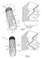
- Fig. 1 illustrates a fixture 10 according to at least a first example embodiment of the present invention.
- the fixture 10 has a coronal portion 12 extending apically from a coronal end 18 of the fixture 10, and an apical portion 16 extending coronally from an apical end 20 of the fixture 10.
- An intermediate portion 14 extends between the coronal portion 12 and the apical portion 16.
- the apical portion 16 has a conicity tapering towards the apical end 20 of the fixture 10 to ease insertion of the fixture 10 into a bore-hole.
- the angle of taper relative to the longitudinal axis X of the fixture 10 may, for instance, be about 10°-20°, such as 15°.
- the apical portion of the fixture may be provided with an external thread. Whether provided with thread or not, the apical portion 16 may optionally, similarly to the coronal and/or the intermediate portion, further be provided with a blasted surface structure.
- the fixture 10 has a core 11 from which a surface structure projects, in the illustrated example being in the form of threads 22, 24.
- the coronal portion 12 is herein illustrated as being at least partly provided with microthreads 22, having three thread spirals, although another number is conceivable, such as 1, 2, 4 or more.
- microthreads have been illustrated, according to at least an alternative example embodiment the coronal portion is at least partly provided with macrothreads 24, similarly to the intermediate portion 14, either as a separate thread spiral or as a continuation of the thread spiral at the intermediate portion 14.
- the coronal portion instead of microthreads, may be provided with a plurality of annular ridges, which to the naked eye could give the same visual appearance as microthreads.
- Other conceivable alternatives are circumferential lines of beads or non-oriented/randomly provided projections such as bulges.
- the macrothreads 24 at the intermediate portion 14 has the same lead as the microthreads 22 at the coronal portion 12.
- the pitch of the macrothreads 24 is three times the pitch of the microthreads 22, since the microthreads 22 comprise three thread spirals.
- the length of the herein illustrated coronal portion 12 may be about 1-2 mm, such as 1.5 mm. However, shorter or longer lengths are readily conceivable.
- the relative length of coronal portion 12 may also be selected from a wide range, such as 5-50% of the total length of the fixture 10, e.g. 10-20%.
- the coronal portion 12 comprises a tapering end portion 26, which tapers towards the coronal end 18 of the fixture 10.
- the tapering end portion 26 is no more than 4% of the total length of the fixture 10.
- the surface of the tapering portion 26 may be non-threaded, either smooth or blasted. Such a tapering portion 26 is more clearly visible in the example embodiment of Fig. 6 (reference numeral 626).
- the intermediate portion 14 comprises macrothreads 24. Although illustrated as having one thread spiral, the intermediate portion 14 may alternatively have two or more thread spirals. Similarly, although illustrated as having a substantially straight cylindrical shape, the intermediate portion 14 may have a slight conicity, i.e. a slightly tapering shape towards the apical portion 16, in which case the angle of taper may e.g. be 3° or less, such as about 1°-2°.
- a cutting recess 28 or groove extends from the apical end 20 into the intermediate portion 14.
- the fixture 10 may have more, such as two, three or four cutting recesses 28, suitably symmetrically positioned about the circumference of the apical end 20 of the fixture 10 for self-tapping of the fixture 10 when being screwed/rotated into the bore-hole provided in the maxilla or mandible.
- the apical portion 16 and the intermediate portion 14 are provided with a plurality of shallow channels 30 at the external fixture surface.
- the channels 30 are herein illustrated as extending in parallel to each other.
- the channels 30 are herein also illustrated as having a main direction of extension somewhat inclined and non-parallel relative to the longitudinal axis X of the fixture 10.
- other inclinations are readily conceivable, and they may or may not be parallel with each other or the longitudinal axis X of the fixture 10.
- the channels 30 may even be inclined to such extent that they form spirals around the longitudinal axis X of the fixture 10.
- the channels 30 form roller-coaster like paths as they go from a coronal flank 34 to an apical flank 36 and continues to the next coronal flank and next apical flank, etc.
- the channels 30 and channel bottoms 32 form paths which extend alternatingly and repeatedly along thread bottoms 38 and thread tops 40.
- the channel bottom 32 extends along a path extending from the core 11 of the fixture 10 towards a structure top (in this example: a thread top 40), wherein the depth of the channel 30 is smaller than the height of the surface structure (in this example: the height of the thread 24).
- the part of the bone tissue which is in contact with the thread is likely to initially be resorbed.
- the channels 30 there will also directly after installation, be small gaps between the thread and the bone tissue. In those gaps between the channel bottom 32 and the surrounding bone blood is allowed to flow and stimulate in-growth of bone tissue.
- the presence of blood is highest near the core of the fixture body, i.e. at the thread bottoms 38, in which case the channels 30 extending along the flanks 34, 36 radially towards the periphery of the threads will advantageously distribute the blood in that direction.
- FIG. 1 illustrates the provision of channels 30 at the apical portion 16 and although the apical portion 16 may be provided with threads, an alternative would be to only have channels 30 at the intermediate portion 14 (see e.g. example embodiment of Fig. 3 ). Furthermore, it would be conceivable to have only part of the length of the intermediate portion 14 provided with channels, such as the part of the intermediate portion extending coronally of the cutting recess 28.
- Fig. 1 also illustrates a cross-sectional view of a channel 30.
- the channel bottom 32 substantially follows the variations of the thread profile relative to the longitudinal axis of the fixture, and thus the depth of the channel 30 is smaller than the depth (height) of the thread.
- the depth of the channel 30 may suitably be about 0.15 mm or less, preferably 0.1 mm or less, more preferably 0.05 mm - 0.1 mm.
- the depth of the channel 30 may suitably be 50% or less than 50% of the thread height, preferably 30% or less than 30% of thread height, more preferably 15%-30% of the thread height.
- a channel 30 may have any one of a number of conceivable shapes, its depth 32, should be understood to imply the maximum depth.
- a channel may have a varying depth along its extension.
- the width of the channel has been illustrated as being constant, it is conceivable to allow its width to vary along the extension of the channel.
- a channel may at one or more points becom bifurcated or branched into several spread channels. For instance, in order to distribute blood over a large area, the "stem" channel may run from a thread bottom and then be divided into a number of "branch” channels on its way towards the thread top.
- Fig. 2 illustrates a fixture 210 according to at least a second example embodiment of the present invention.
- the fixture 210 is also provided with a second set of channels 230b having a main direction of extension which is angled relative to the main direction of extension of the first set.
- the channels 230a in the first set cross the paths of the channels 230b of the second set, thereby forming a diamond-like pattern.
- the thread flanks 234, 236 of a fixture 210 according to Fig. 2 may thus be provided with a larger bone in-growth stimulating area compared to a fixture 10 according to Fig. 1 .
- crossing channels 230a, 230b form a system of blood canals which may further enhance the blood distribution and in-growth stimulation.
- the various alternatives and features discussed in relation to the fixture 10 illustrated in Fig. 1 may readily be implemented also for exemplified fixture 210 of Fig. 2 .
- Fig. 3 illustrates a fixture 310 according to at least a third example embodiment of the invention.
- the coronal thread flanks 334 are provided with relatively short channels 330a, 330b, while the apical thread flanks 336 are void of channels.
- the channels on the coronal flanks 334 have the advantage of enabling blood distribution
- the lack of channels at the apical flank 336 may have the advantage of maintaining the load bearing capability on the apical flanks 336 since the initial load is distributed over a larger area than what would be the case if the apical flanks were provided with channels.
- the apical thread flanks 336 may be provided with relatively short channels, while the coronal thread flanks 334 are void of channels. This may be advantageous from a bone generation promoting perspective.
- the implant When the implant is subjected to an axial load, the implant is pressed in an apical direction, which means that the contact/pressure is reduced on the coronal flanks and increased on the apical flanks.
- the role of the coronal flanks may be reduced, and as an option, channels could be omitted on the coronal flanks.
- a channel on the apical flank would result in that the bone area facing the channel is not subjected to pressure when the implant is axially loaded, and consequently reduce the risk of resorption.
- Yet another alternative is to have some sub-portion provided with channels located only on the coronal flanks and another sub-portion provided with channels only located on the apical flanks.
- the extension of the short channels 330a, 330b on a flank 334 are herein illustrated as being nonparallel, however, parallel channels is a conceivable alternative.
- the channels 330a, 330b have been illustrated as extending all the way from thread bottom 338 to thread top 340, an alternative would be to extend only part of the distance between the thread bottom 338 and the thread top 340.
- the features and alternatives discussed in connection with the embodiment of Fig. 3 may be combined with above-discussed features and alternatives presented in the connection with Figs. 1 and 2 .
- Fig. 4 illustrates a portion of a fixture according to at least a fourth example embodiment of the present invention.
- a shallow channel 430 is located in a plane P which is perpendicular to the longitudinal axis X of the fixture, i.e. the longitudinal axis X forms a normal to the plane P.
- the thread spiral 450 is inclined relative to said plane P, i.e. being non-parallel with the channel 430.
- the thread spiral 450 will be inclined relative to the plane P.
- the thread spiral(s) is/are non-parallel with the extension of the channels. This will have the effect that the channel 430(and channel bottom) will extend from a thread top 440 to a thread bottom 438.
- the channel 430 may extend all the way around the periphery of the fixture, thus forming an annulus, or may alternatively, extend along part of the periphery.
- the number of thread bottoms 438 and tops 440 passed by the channel 430 will depend on the lead of the thread 450, the extent of the channel 430 and the angle of the plane P relative to the longitudinal axis X (since the plane P may be inclined at an angle which is different from what is illustrated in the drawing).
- the fixture may be provided with a plurality of other such channels lying in planes being parallel or non-parallel with the indicated plane P.
- the plurality of channels may describe a full annular path or, alternatively, extend partly around the fixture body.
- a fixture may comprise annular channels 430 as well as a diamond-like channel pattern.
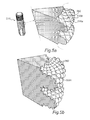
- Fig. 5a illustrates a fixture 510 according to at least a fifth example embodiment of the invention.
- a plurality of channels 530a, 530b are provided in a grid-like tight pattern, such that only pyramidal peaks 560 are formed on the flank surface. This provides for a large area of continuous blood canals/gaps between the bone and the fixture.
- An alternative is illustrated in the enlarged cut-out view shown in Fig. 5b , wherein a plurality of channels 530c are also provided in a grid-like pattern but have varying width, thereby forming bulges 562 on the flank surface.
- a fixture may comprise annular channels as well as the tight grid-like pattern.
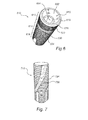
- Fig. 6 illustrates a fixture 610 according to at least a sixth example embodiment of the invention.
- the illustrated fixture 610 is provided with microthreads 622 at the coronal portion 612 of the fixture 610 and provided with macrothreads 624 at the apical 616 and intermediate portions 614 of the fixture 610, and a plurality of channels 630 are provided crossing each other, similarly to the illustration in Fig. 2 , however, here illustrated with a tighter channel pattern.
- Fig. 6 illustrates a socket 660 having an open end in the coronal end 618 of the fixture 610. The socket 660 extends apically into the fixture 610.
- the socket 660 is for receiving an abutment structure (not shown) which will bridge the gingiva overlying the bore-hole and support/present a prosthetic part.
- the socket 660 has a conical coronal section 662, an internally threaded apical section (not shown) and an cylindrical or, as illustrated, hexagonal (or other polygonal) intermediate section 664.
- the conical coronal section 664 may have an angle of taper relative to the longitudinal axis of the fixture of in the range of 7°-15°, such as 10°-12°.
- the abutment structure will have an apical section which is able to be screw-retained in the fixture socket 660 for releasably securing the abutment structure to the fixture 610, and a conical section for providing a conical seal with coronal section 662 of the socket 660.
- Fig. 7 illustrates a fixture 710 according to at least a seventh example embodiment of the invention.
- the fixture 710 is provided with wide channels 730. Their width corresponding to about a sixth of the circumference of the fixture 710.
- the channels 730 are somewhat curved in the apical-to-coronal direction and form a roller-coaster path up and down the thread tops and thread bottoms.
- the channels 730 may, as conceivable alternatives, be provided with more or less curvature than illustrated, or even be substantially linear in the apical-to-coronal direction.
- the wide channels 730 may be provided on macrothreads 724 extending along most of the fixture length, such wide channels may be provided on other previously discussed projecting surface structures, such as microthreads, ridges, beads, etc.
- the features and alternatives discussed in connection with the embodiment of Fig. 7 may be combined with above-discussed features and alternatives presented in the connection with Figs. 1 to 6 .
- Fig. 8 illustrates a fixture 810 according to at least an eighth example embodiment of the invention.
- the fixture 810 is provided with circumferentially extending ridges 823 which are radially projecting from the core of the fixture 810.
- the ridges suitably projects about 0.2 mm or less from the core, i.e. similarly to microthreads, however, other ridge heights are readily conceivable.
- the ridges 823 are intended to be annular, an alternative would be to have one or more ridges forming part or parts of a circle. As illustrated in the enlarged cut-out view of Fig.
- channels 830a, 830b are provided in a criss-cross manner over the ridges 823.
- each ridge 823 lies in a plane which is perpendicular to the longitudinal axis of the fixture 810, i.e. the longitudinal axis X is normal to said plane.
- one or more ridges could extend in a plane which is at another angle to the longitudinal axis or even at a zero angle to the longitudinal axis of the fixture 810.
- Fig. 9 illustrates a fixture 910 according to at least a ninth example embodiment of the invention.
- a coronal portion 912 of the fixture 910 a non-oriented surface structure projecting from the core 911 of the fixture 910 is provided.
- the surface structure is herein represented by randomly provided bulges 925, as illustrated in the enlarged cut-out view of Fig. 9 .
- Channels 930a, 930b run crosswise in a roller-coaster fashion up and down the bulges 925.
- the height of a bulge 925 is suitably 0.2 mm or less, however other heights are conceivable.
- the features and alternatives discussed in connection with the embodiment of Fig. 9 may be combined with above-discussed features and alternatives presented in the connection with Figs. 1 to 8 .
Priority Applications (9)
| Application Number | Priority Date | Filing Date | Title |
|---|---|---|---|
| EP20090155873 EP2233108B1 (fr) | 2009-03-23 | 2009-03-23 | Implant osseux |
| AU2010227669A AU2010227669B2 (en) | 2009-03-23 | 2010-03-12 | Bone fixture |
| CA2755381A CA2755381A1 (fr) | 2009-03-23 | 2010-03-12 | Dispositif de fixation osseuse |
| US12/659,541 US20100240010A1 (en) | 2009-03-23 | 2010-03-12 | Fixture |
| CN201080011966.5A CN102355867B (zh) | 2009-03-23 | 2010-03-12 | 固定装置 |
| PCT/EP2010/053166 WO2010108794A1 (fr) | 2009-03-23 | 2010-03-12 | Dispositif de fixation osseuse |
| JP2012501235A JP2012521232A (ja) | 2009-03-23 | 2010-03-12 | 骨固定具 |
| BRPI1013870-6A BRPI1013870A2 (pt) | 2009-03-23 | 2010-03-12 | implante |
| KR1020117024570A KR20110129965A (ko) | 2009-03-23 | 2010-03-12 | 뼈 고정구 |
Applications Claiming Priority (1)
| Application Number | Priority Date | Filing Date | Title |
|---|---|---|---|
| EP20090155873 EP2233108B1 (fr) | 2009-03-23 | 2009-03-23 | Implant osseux |
Publications (2)
| Publication Number | Publication Date |
|---|---|
| EP2233108A1 true EP2233108A1 (fr) | 2010-09-29 |
| EP2233108B1 EP2233108B1 (fr) | 2015-04-29 |
Family
ID=40984937
Family Applications (1)
| Application Number | Title | Priority Date | Filing Date |
|---|---|---|---|
| EP20090155873 Active EP2233108B1 (fr) | 2009-03-23 | 2009-03-23 | Implant osseux |
Country Status (9)
| Country | Link |
|---|---|
| US (1) | US20100240010A1 (fr) |
| EP (1) | EP2233108B1 (fr) |
| JP (1) | JP2012521232A (fr) |
| KR (1) | KR20110129965A (fr) |
| CN (1) | CN102355867B (fr) |
| AU (1) | AU2010227669B2 (fr) |
| BR (1) | BRPI1013870A2 (fr) |
| CA (1) | CA2755381A1 (fr) |
| WO (1) | WO2010108794A1 (fr) |
Cited By (9)
| Publication number | Priority date | Publication date | Assignee | Title |
|---|---|---|---|---|
| WO2011039162A1 (fr) * | 2009-10-01 | 2011-04-07 | Ornaghi Luigi & C. S.N.C. Di Ornaghi Giuseppe Ed Angelo | Implant dentaire présentant des caractéristiques d'ostéointégration améliorées |
| EP2510900A1 (fr) * | 2011-04-14 | 2012-10-17 | Astra Tech AB | Dispositif de fixation |
| EP2510899A1 (fr) * | 2011-04-14 | 2012-10-17 | Astra Tech AB | Dispositif de fixation |
| WO2013119754A1 (fr) | 2007-11-19 | 2013-08-15 | Medical Facets, Llc | Vis à os et son procédé de fabrication |
| CN104144652A (zh) * | 2012-02-09 | 2014-11-12 | 奥瑟派帝克就医通道有限责任公司 | 接骨螺钉和用于制造其的方法 |
| EP2967582A4 (fr) * | 2013-03-13 | 2016-10-05 | Blackstone Medical Inc | Vis pédiculaire à découpe en spirale inverse et méthodes associées |
| EP3192470A1 (fr) * | 2016-01-12 | 2017-07-19 | Bernd Milbrodt | Implant dentaire comprenant un filetage a filets multiples |
| EP3473188A1 (fr) * | 2012-02-13 | 2019-04-24 | Medical Facets LLC | Vis à os à facettes |
| US11426261B2 (en) | 2011-04-14 | 2022-08-30 | Dentsply Sirona Inc. | Fixture |
Families Citing this family (22)
| Publication number | Priority date | Publication date | Assignee | Title |
|---|---|---|---|---|
| US9173042B2 (en) | 2007-07-20 | 2015-10-27 | Cochlear Limited | Bone anchor fixture for a medical prosthesis |
| US9848927B2 (en) * | 2009-01-27 | 2017-12-26 | Intra-Lock International, Inc. | Self-clearing self-cutting implant |
| ES2687256T3 (es) * | 2009-01-27 | 2018-10-24 | Intra-Lock International Inc. | Implante autorroscante |
| US10064707B2 (en) * | 2011-07-20 | 2018-09-04 | Parsa T. Zadeh | Self-osteotomizing bone implant and related method |
| WO2013025702A1 (fr) | 2011-08-16 | 2013-02-21 | Osteospring Medical, Inc. | Dispositifs de fixation de fracture en forme de coude et procédés d'utilisation associés |
| US9782209B2 (en) | 2012-10-03 | 2017-10-10 | Rtg Scientific | Medical fastener |
| US11240613B2 (en) * | 2014-01-30 | 2022-02-01 | Cochlear Limited | Bone conduction implant |
| GB2523827A (en) | 2014-03-07 | 2015-09-09 | Nobel Biocare Services Ag | Dental implant |
| GB2523828A (en) | 2014-03-07 | 2015-09-09 | Nobel Biocare Services Ag | Dental implant |
| IL237117A (en) * | 2015-02-05 | 2017-07-31 | Alpha Bio Tec Ltd | Dental implant to stabilize and facilitate insertion into the implant site |
| KR101647995B1 (ko) * | 2015-02-10 | 2016-08-17 | (주) 신한씨스텍 | 봉합사 앵커 |
| JP2016214369A (ja) * | 2015-05-15 | 2016-12-22 | 恭久 高橋 | フィクスチャー |
| US11051915B2 (en) * | 2016-11-10 | 2021-07-06 | Nantoh. Co., Ltd. | Biological tissue rootage face, implant, method for forming biological tissue rootage face, and method for producing implant |
| JP6373936B2 (ja) * | 2016-11-16 | 2018-08-15 | 慶達科技股▲ふん▼有限公司 | 歯根インプラント |
| US11382724B2 (en) * | 2017-10-11 | 2022-07-12 | Evollution Ip Holdings, Inc. | Three-dimensional stabilization thread form for dental implants |
| CN110234286B (zh) | 2017-12-06 | 2022-07-01 | 史赛克欧洲运营控股有限责任公司 | 整形用锁定螺钉 |
| US20190374312A1 (en) * | 2018-06-07 | 2019-12-12 | Taiwan Shan Yin International Co., Ltd. | Implant device |
| US20220047359A1 (en) | 2018-10-22 | 2022-02-17 | Huwais IP Holding LLC | Anchor with healing chambers |
| AT522112B1 (de) * | 2019-01-16 | 2021-01-15 | Surgebright Gmbh | Knochentransplantat |
| CN110368114B (zh) * | 2019-08-05 | 2021-06-22 | 四川大学 | 用预成嵌体封闭牙种植上部修复螺丝孔的数字化设计方法 |
| US11559375B2 (en) * | 2020-07-16 | 2023-01-24 | Leszek Aleksander Tomasik | Diamond dental teeth formed by using laser energy |
| US20220015813A1 (en) * | 2020-07-20 | 2022-01-20 | Nicholas Cordaro | Medical Fastener or Device with Dual Surface Topography |
Citations (11)
| Publication number | Priority date | Publication date | Assignee | Title |
|---|---|---|---|---|
| FR2610512A1 (fr) * | 1987-02-06 | 1988-08-12 | Cuilleron J | Procede et moyens d'ancrage d'elements d'implants visses dans les tissus osseux et les elements d'implants obtenus |
| EP0714643A1 (fr) * | 1994-12-02 | 1996-06-05 | JOHNSON & JOHNSON PROFESSIONAL Inc. | Dispositif de fixation des os |
| DE29703296U1 (de) * | 1997-02-11 | 1998-06-04 | Ransmayer A & Rodrian A | Implantat, insbesondere Zahnwurzelimplantat |
| US6419491B1 (en) * | 1993-11-02 | 2002-07-16 | Bio-Lok International, Inc. | Dental implant system with repeating microgeometric surface patterns |
| WO2003055405A1 (fr) * | 2001-12-21 | 2003-07-10 | Nobel Biocare Ab (Publ) | Implant et procede de fabrication d'une structure de surface sur l'implant |
| WO2004058091A1 (fr) * | 2002-12-30 | 2004-07-15 | Nobel Biocare Ab (Publ) | Système d'implant |
| EP1440669A1 (fr) * | 2003-01-23 | 2004-07-28 | Dinkelacker, Wolfgang, Dr. med. dent. | Implant osseux et procédé pour sa fabrication |
| US20040170946A1 (en) * | 2003-02-27 | 2004-09-02 | Lyren Philip S. | Dental implant with porous body |
| WO2004098442A1 (fr) * | 2003-05-03 | 2004-11-18 | Wolfgang Dinkelacker | Implant osseux inserable par vissage |
| US20060204930A1 (en) * | 2003-03-26 | 2006-09-14 | Young-Taek Sul | Helical implant |
| DE102006011629A1 (de) * | 2006-03-08 | 2007-09-13 | Mircoceram Gmbh | Verfahren zur Herstellung von Implantaten |
Family Cites Families (6)
| Publication number | Priority date | Publication date | Assignee | Title |
|---|---|---|---|---|
| US5242253A (en) * | 1992-10-08 | 1993-09-07 | Semblex Corporation | Thread-forming screw |
| US5427527A (en) * | 1993-05-25 | 1995-06-27 | Vent Plant Corporation | Dental implant method of installation |
| US5967783A (en) * | 1998-10-19 | 1999-10-19 | Ura; Robert S. | Threaded dental implant with a core to thread ratio facilitating immediate loading and method of installation |
| ATE197389T1 (de) * | 1998-12-11 | 2000-11-11 | Dinkelacker Wolfgang | Zahnimplantat und verfahren zu seiner herstellung |
| US6413089B1 (en) * | 1999-02-10 | 2002-07-02 | Arthur Ashman | Immediate post-extraction implant |
| EP1911412B1 (fr) * | 2006-10-11 | 2011-04-13 | Astra Tech AB | Implant |
-
2009
- 2009-03-23 EP EP20090155873 patent/EP2233108B1/fr active Active
-
2010
- 2010-03-12 WO PCT/EP2010/053166 patent/WO2010108794A1/fr active Application Filing
- 2010-03-12 BR BRPI1013870-6A patent/BRPI1013870A2/pt not_active Application Discontinuation
- 2010-03-12 JP JP2012501235A patent/JP2012521232A/ja active Pending
- 2010-03-12 US US12/659,541 patent/US20100240010A1/en not_active Abandoned
- 2010-03-12 KR KR1020117024570A patent/KR20110129965A/ko not_active Application Discontinuation
- 2010-03-12 CA CA2755381A patent/CA2755381A1/fr not_active Abandoned
- 2010-03-12 AU AU2010227669A patent/AU2010227669B2/en not_active Ceased
- 2010-03-12 CN CN201080011966.5A patent/CN102355867B/zh active Active
Patent Citations (11)
| Publication number | Priority date | Publication date | Assignee | Title |
|---|---|---|---|---|
| FR2610512A1 (fr) * | 1987-02-06 | 1988-08-12 | Cuilleron J | Procede et moyens d'ancrage d'elements d'implants visses dans les tissus osseux et les elements d'implants obtenus |
| US6419491B1 (en) * | 1993-11-02 | 2002-07-16 | Bio-Lok International, Inc. | Dental implant system with repeating microgeometric surface patterns |
| EP0714643A1 (fr) * | 1994-12-02 | 1996-06-05 | JOHNSON & JOHNSON PROFESSIONAL Inc. | Dispositif de fixation des os |
| DE29703296U1 (de) * | 1997-02-11 | 1998-06-04 | Ransmayer A & Rodrian A | Implantat, insbesondere Zahnwurzelimplantat |
| WO2003055405A1 (fr) * | 2001-12-21 | 2003-07-10 | Nobel Biocare Ab (Publ) | Implant et procede de fabrication d'une structure de surface sur l'implant |
| WO2004058091A1 (fr) * | 2002-12-30 | 2004-07-15 | Nobel Biocare Ab (Publ) | Système d'implant |
| EP1440669A1 (fr) * | 2003-01-23 | 2004-07-28 | Dinkelacker, Wolfgang, Dr. med. dent. | Implant osseux et procédé pour sa fabrication |
| US20040170946A1 (en) * | 2003-02-27 | 2004-09-02 | Lyren Philip S. | Dental implant with porous body |
| US20060204930A1 (en) * | 2003-03-26 | 2006-09-14 | Young-Taek Sul | Helical implant |
| WO2004098442A1 (fr) * | 2003-05-03 | 2004-11-18 | Wolfgang Dinkelacker | Implant osseux inserable par vissage |
| DE102006011629A1 (de) * | 2006-03-08 | 2007-09-13 | Mircoceram Gmbh | Verfahren zur Herstellung von Implantaten |
Cited By (23)
| Publication number | Priority date | Publication date | Assignee | Title |
|---|---|---|---|---|
| WO2013119754A1 (fr) | 2007-11-19 | 2013-08-15 | Medical Facets, Llc | Vis à os et son procédé de fabrication |
| US10052144B2 (en) | 2007-11-19 | 2018-08-21 | Orthopedic Medical Channels, Llc | Bone screw and method for manufacturing the same |
| US9713487B2 (en) | 2007-11-19 | 2017-07-25 | Orthopedic Medical Channels, Llc | Bone screw and method for manufacturing the same |
| WO2011039162A1 (fr) * | 2009-10-01 | 2011-04-07 | Ornaghi Luigi & C. S.N.C. Di Ornaghi Giuseppe Ed Angelo | Implant dentaire présentant des caractéristiques d'ostéointégration améliorées |
| US9226804B2 (en) * | 2011-04-14 | 2016-01-05 | Dentsply International Inc. | Fixture and a fixture set and a method |
| US9782239B2 (en) | 2011-04-14 | 2017-10-10 | Dentsply International Inc | Fixture, a thread maker and a fixture set |
| WO2012140164A1 (fr) * | 2011-04-14 | 2012-10-18 | Astra Tech Ab | Fixation |
| US11426261B2 (en) | 2011-04-14 | 2022-08-30 | Dentsply Sirona Inc. | Fixture |
| EP2510900A1 (fr) * | 2011-04-14 | 2012-10-17 | Astra Tech AB | Dispositif de fixation |
| AU2012241849B2 (en) * | 2011-04-14 | 2015-11-26 | Dentsply Ih Ab | A fixture, a thread maker and a fixture set |
| US20120264083A1 (en) * | 2011-04-14 | 2012-10-18 | Anders Halldin | Fixture and a fixture set and a method |
| WO2012140167A3 (fr) * | 2011-04-14 | 2012-12-06 | Dentsply Ih Ab | Fixation, dispositif de réalisation de filetage, et ensemble de fixation |
| EP2510899A1 (fr) * | 2011-04-14 | 2012-10-17 | Astra Tech AB | Dispositif de fixation |
| RU2626963C2 (ru) * | 2012-02-09 | 2017-08-02 | ОРТОПЕДИК МЕДИКАЛ ЧЕННЕЛС, ЭлЭлСи | Костный винт и способ его изготовления |
| AU2013217063B2 (en) * | 2012-02-09 | 2017-08-03 | Orthopedic Medical Channels, Llc | Bone screw and method for manufacturing the same |
| EP2811926A4 (fr) * | 2012-02-09 | 2015-10-14 | Orthopedic Medical Channels Llc | Vis à os et son procédé de fabrication |
| EP3530226A1 (fr) * | 2012-02-09 | 2019-08-28 | Orthopedic Medical Channels, LLC | Vis osseuse et son procédé de fabrication |
| CN104144652A (zh) * | 2012-02-09 | 2014-11-12 | 奥瑟派帝克就医通道有限责任公司 | 接骨螺钉和用于制造其的方法 |
| EP3473188A1 (fr) * | 2012-02-13 | 2019-04-24 | Medical Facets LLC | Vis à os à facettes |
| US9636158B2 (en) | 2013-03-13 | 2017-05-02 | Blackstone Medical, Inc. | Pedicle screw with reverse spiral cut and methods thereof |
| EP2967582A4 (fr) * | 2013-03-13 | 2016-10-05 | Blackstone Medical Inc | Vis pédiculaire à découpe en spirale inverse et méthodes associées |
| EP3782561A1 (fr) * | 2013-03-13 | 2021-02-24 | Blackstone Medical, Inc. | Vis pédiculaire à découpe en spirale inverse |
| EP3192470A1 (fr) * | 2016-01-12 | 2017-07-19 | Bernd Milbrodt | Implant dentaire comprenant un filetage a filets multiples |
Also Published As
| Publication number | Publication date |
|---|---|
| CN102355867B (zh) | 2014-09-17 |
| AU2010227669A1 (en) | 2011-09-29 |
| US20100240010A1 (en) | 2010-09-23 |
| WO2010108794A1 (fr) | 2010-09-30 |
| EP2233108B1 (fr) | 2015-04-29 |
| CA2755381A1 (fr) | 2010-09-30 |
| BRPI1013870A2 (pt) | 2020-12-01 |
| KR20110129965A (ko) | 2011-12-02 |
| JP2012521232A (ja) | 2012-09-13 |
| CN102355867A (zh) | 2012-02-15 |
| AU2010227669B2 (en) | 2012-12-06 |
Similar Documents
| Publication | Publication Date | Title |
|---|---|---|
| EP2233108B1 (fr) | Implant osseux | |
| US11426261B2 (en) | Fixture | |
| EP1416872B2 (fr) | Implant osseux | |
| US11413119B2 (en) | Fixture and a fixture set | |
| CA2832385C (fr) | Fixation, dispositif de realisation de filetage, et ensemble de fixation | |
| CA2894651C (fr) | Implant condenseur | |
| US20140200620A1 (en) | Implantable fixture | |
| WO2000003656A1 (fr) | Implant dentaire | |
| US9226804B2 (en) | Fixture and a fixture set and a method |
Legal Events
| Date | Code | Title | Description |
|---|---|---|---|
| PUAI | Public reference made under article 153(3) epc to a published international application that has entered the european phase |
Free format text: ORIGINAL CODE: 0009012 |
|
| AK | Designated contracting states |
Kind code of ref document: A1 Designated state(s): AT BE BG CH CY CZ DE DK EE ES FI FR GB GR HR HU IE IS IT LI LT LU LV MC MK MT NL NO PL PT RO SE SI SK TR |
|
| AX | Request for extension of the european patent |
Extension state: AL BA RS |
|
| 17P | Request for examination filed |
Effective date: 20110311 |
|
| 17Q | First examination report despatched |
Effective date: 20110331 |
|
| AKX | Designation fees paid |
Designated state(s): AT BE BG CH CY CZ DE DK EE ES FI FR GB GR HR HU IE IS IT LI LT LU LV MC MK MT NL NO PL PT RO SE SI SK TR |
|
| RAP1 | Party data changed (applicant data changed or rights of an application transferred) |
Owner name: DENTSPLY IH AB |
|
| GRAP | Despatch of communication of intention to grant a patent |
Free format text: ORIGINAL CODE: EPIDOSNIGR1 |
|
| INTG | Intention to grant announced |
Effective date: 20150129 |
|
| GRAS | Grant fee paid |
Free format text: ORIGINAL CODE: EPIDOSNIGR3 |
|
| GRAA | (expected) grant |
Free format text: ORIGINAL CODE: 0009210 |
|
| AK | Designated contracting states |
Kind code of ref document: B1 Designated state(s): AT BE BG CH CY CZ DE DK EE ES FI FR GB GR HR HU IE IS IT LI LT LU LV MC MK MT NL NO PL PT RO SE SI SK TR |
|
| REG | Reference to a national code |
Ref country code: GB Ref legal event code: FG4D |
|
| REG | Reference to a national code |
Ref country code: CH Ref legal event code: EP |
|
| REG | Reference to a national code |
Ref country code: AT Ref legal event code: REF Ref document number: 724014 Country of ref document: AT Kind code of ref document: T Effective date: 20150515 |
|
| REG | Reference to a national code |
Ref country code: IE Ref legal event code: FG4D |
|
| REG | Reference to a national code |
Ref country code: DE Ref legal event code: R096 Ref document number: 602009030914 Country of ref document: DE Effective date: 20150611 |
|
| REG | Reference to a national code |
Ref country code: SE Ref legal event code: TRGR |
|
| REG | Reference to a national code |
Ref country code: NL Ref legal event code: VDEP Effective date: 20150429 |
|
| REG | Reference to a national code |
Ref country code: AT Ref legal event code: MK05 Ref document number: 724014 Country of ref document: AT Kind code of ref document: T Effective date: 20150429 |
|
| REG | Reference to a national code |
Ref country code: LT Ref legal event code: MG4D |
|
| PG25 | Lapsed in a contracting state [announced via postgrant information from national office to epo] |
Ref country code: NL Free format text: LAPSE BECAUSE OF FAILURE TO SUBMIT A TRANSLATION OF THE DESCRIPTION OR TO PAY THE FEE WITHIN THE PRESCRIBED TIME-LIMIT Effective date: 20150429 |
|
| PG25 | Lapsed in a contracting state [announced via postgrant information from national office to epo] |
Ref country code: FI Free format text: LAPSE BECAUSE OF FAILURE TO SUBMIT A TRANSLATION OF THE DESCRIPTION OR TO PAY THE FEE WITHIN THE PRESCRIBED TIME-LIMIT Effective date: 20150429 Ref country code: HR Free format text: LAPSE BECAUSE OF FAILURE TO SUBMIT A TRANSLATION OF THE DESCRIPTION OR TO PAY THE FEE WITHIN THE PRESCRIBED TIME-LIMIT Effective date: 20150429 Ref country code: ES Free format text: LAPSE BECAUSE OF FAILURE TO SUBMIT A TRANSLATION OF THE DESCRIPTION OR TO PAY THE FEE WITHIN THE PRESCRIBED TIME-LIMIT Effective date: 20150429 Ref country code: PT Free format text: LAPSE BECAUSE OF FAILURE TO SUBMIT A TRANSLATION OF THE DESCRIPTION OR TO PAY THE FEE WITHIN THE PRESCRIBED TIME-LIMIT Effective date: 20150831 Ref country code: NO Free format text: LAPSE BECAUSE OF FAILURE TO SUBMIT A TRANSLATION OF THE DESCRIPTION OR TO PAY THE FEE WITHIN THE PRESCRIBED TIME-LIMIT Effective date: 20150729 Ref country code: LT Free format text: LAPSE BECAUSE OF FAILURE TO SUBMIT A TRANSLATION OF THE DESCRIPTION OR TO PAY THE FEE WITHIN THE PRESCRIBED TIME-LIMIT Effective date: 20150429 |
|
| PG25 | Lapsed in a contracting state [announced via postgrant information from national office to epo] |
Ref country code: GR Free format text: LAPSE BECAUSE OF FAILURE TO SUBMIT A TRANSLATION OF THE DESCRIPTION OR TO PAY THE FEE WITHIN THE PRESCRIBED TIME-LIMIT Effective date: 20150730 Ref country code: LV Free format text: LAPSE BECAUSE OF FAILURE TO SUBMIT A TRANSLATION OF THE DESCRIPTION OR TO PAY THE FEE WITHIN THE PRESCRIBED TIME-LIMIT Effective date: 20150429 Ref country code: AT Free format text: LAPSE BECAUSE OF FAILURE TO SUBMIT A TRANSLATION OF THE DESCRIPTION OR TO PAY THE FEE WITHIN THE PRESCRIBED TIME-LIMIT Effective date: 20150429 Ref country code: IS Free format text: LAPSE BECAUSE OF FAILURE TO SUBMIT A TRANSLATION OF THE DESCRIPTION OR TO PAY THE FEE WITHIN THE PRESCRIBED TIME-LIMIT Effective date: 20150829 |
|
| PG25 | Lapsed in a contracting state [announced via postgrant information from national office to epo] |
Ref country code: EE Free format text: LAPSE BECAUSE OF FAILURE TO SUBMIT A TRANSLATION OF THE DESCRIPTION OR TO PAY THE FEE WITHIN THE PRESCRIBED TIME-LIMIT Effective date: 20150429 Ref country code: DK Free format text: LAPSE BECAUSE OF FAILURE TO SUBMIT A TRANSLATION OF THE DESCRIPTION OR TO PAY THE FEE WITHIN THE PRESCRIBED TIME-LIMIT Effective date: 20150429 |
|
| REG | Reference to a national code |
Ref country code: DE Ref legal event code: R097 Ref document number: 602009030914 Country of ref document: DE |
|
| PG25 | Lapsed in a contracting state [announced via postgrant information from national office to epo] |
Ref country code: PL Free format text: LAPSE BECAUSE OF FAILURE TO SUBMIT A TRANSLATION OF THE DESCRIPTION OR TO PAY THE FEE WITHIN THE PRESCRIBED TIME-LIMIT Effective date: 20150429 Ref country code: RO Free format text: LAPSE BECAUSE OF NON-PAYMENT OF DUE FEES Effective date: 20150429 Ref country code: CZ Free format text: LAPSE BECAUSE OF FAILURE TO SUBMIT A TRANSLATION OF THE DESCRIPTION OR TO PAY THE FEE WITHIN THE PRESCRIBED TIME-LIMIT Effective date: 20150429 Ref country code: SK Free format text: LAPSE BECAUSE OF FAILURE TO SUBMIT A TRANSLATION OF THE DESCRIPTION OR TO PAY THE FEE WITHIN THE PRESCRIBED TIME-LIMIT Effective date: 20150429 |
|
| PLBE | No opposition filed within time limit |
Free format text: ORIGINAL CODE: 0009261 |
|
| STAA | Information on the status of an ep patent application or granted ep patent |
Free format text: STATUS: NO OPPOSITION FILED WITHIN TIME LIMIT |
|
| 26N | No opposition filed |
Effective date: 20160201 |
|
| PG25 | Lapsed in a contracting state [announced via postgrant information from national office to epo] |
Ref country code: IT Free format text: LAPSE BECAUSE OF FAILURE TO SUBMIT A TRANSLATION OF THE DESCRIPTION OR TO PAY THE FEE WITHIN THE PRESCRIBED TIME-LIMIT Effective date: 20150429 |
|
| PG25 | Lapsed in a contracting state [announced via postgrant information from national office to epo] |
Ref country code: SI Free format text: LAPSE BECAUSE OF FAILURE TO SUBMIT A TRANSLATION OF THE DESCRIPTION OR TO PAY THE FEE WITHIN THE PRESCRIBED TIME-LIMIT Effective date: 20150429 |
|
| PG25 | Lapsed in a contracting state [announced via postgrant information from national office to epo] |
Ref country code: BE Free format text: LAPSE BECAUSE OF FAILURE TO SUBMIT A TRANSLATION OF THE DESCRIPTION OR TO PAY THE FEE WITHIN THE PRESCRIBED TIME-LIMIT Effective date: 20150429 |
|
| PG25 | Lapsed in a contracting state [announced via postgrant information from national office to epo] |
Ref country code: MC Free format text: LAPSE BECAUSE OF FAILURE TO SUBMIT A TRANSLATION OF THE DESCRIPTION OR TO PAY THE FEE WITHIN THE PRESCRIBED TIME-LIMIT Effective date: 20150429 Ref country code: LU Free format text: LAPSE BECAUSE OF FAILURE TO SUBMIT A TRANSLATION OF THE DESCRIPTION OR TO PAY THE FEE WITHIN THE PRESCRIBED TIME-LIMIT Effective date: 20160323 |
|
| REG | Reference to a national code |
Ref country code: CH Ref legal event code: PL |
|
| GBPC | Gb: european patent ceased through non-payment of renewal fee |
Effective date: 20160323 |
|
| REG | Reference to a national code |
Ref country code: IE Ref legal event code: MM4A |
|
| REG | Reference to a national code |
Ref country code: FR Ref legal event code: ST Effective date: 20161130 |
|
| PG25 | Lapsed in a contracting state [announced via postgrant information from national office to epo] |
Ref country code: IE Free format text: LAPSE BECAUSE OF NON-PAYMENT OF DUE FEES Effective date: 20160323 Ref country code: CH Free format text: LAPSE BECAUSE OF NON-PAYMENT OF DUE FEES Effective date: 20160331 Ref country code: FR Free format text: LAPSE BECAUSE OF NON-PAYMENT OF DUE FEES Effective date: 20160331 Ref country code: LI Free format text: LAPSE BECAUSE OF NON-PAYMENT OF DUE FEES Effective date: 20160331 Ref country code: GB Free format text: LAPSE BECAUSE OF NON-PAYMENT OF DUE FEES Effective date: 20160323 |
|
| PG25 | Lapsed in a contracting state [announced via postgrant information from national office to epo] |
Ref country code: MT Free format text: LAPSE BECAUSE OF FAILURE TO SUBMIT A TRANSLATION OF THE DESCRIPTION OR TO PAY THE FEE WITHIN THE PRESCRIBED TIME-LIMIT Effective date: 20150429 |
|
| PG25 | Lapsed in a contracting state [announced via postgrant information from national office to epo] |
Ref country code: CY Free format text: LAPSE BECAUSE OF FAILURE TO SUBMIT A TRANSLATION OF THE DESCRIPTION OR TO PAY THE FEE WITHIN THE PRESCRIBED TIME-LIMIT Effective date: 20150429 Ref country code: HU Free format text: LAPSE BECAUSE OF FAILURE TO SUBMIT A TRANSLATION OF THE DESCRIPTION OR TO PAY THE FEE WITHIN THE PRESCRIBED TIME-LIMIT; INVALID AB INITIO Effective date: 20090323 |
|
| PG25 | Lapsed in a contracting state [announced via postgrant information from national office to epo] |
Ref country code: MK Free format text: LAPSE BECAUSE OF FAILURE TO SUBMIT A TRANSLATION OF THE DESCRIPTION OR TO PAY THE FEE WITHIN THE PRESCRIBED TIME-LIMIT Effective date: 20150429 Ref country code: MT Free format text: LAPSE BECAUSE OF FAILURE TO SUBMIT A TRANSLATION OF THE DESCRIPTION OR TO PAY THE FEE WITHIN THE PRESCRIBED TIME-LIMIT Effective date: 20160331 Ref country code: TR Free format text: LAPSE BECAUSE OF FAILURE TO SUBMIT A TRANSLATION OF THE DESCRIPTION OR TO PAY THE FEE WITHIN THE PRESCRIBED TIME-LIMIT Effective date: 20150429 |
|
| PG25 | Lapsed in a contracting state [announced via postgrant information from national office to epo] |
Ref country code: BG Free format text: LAPSE BECAUSE OF FAILURE TO SUBMIT A TRANSLATION OF THE DESCRIPTION OR TO PAY THE FEE WITHIN THE PRESCRIBED TIME-LIMIT Effective date: 20150429 |
|
| PGFP | Annual fee paid to national office [announced via postgrant information from national office to epo] |
Ref country code: SE Payment date: 20230210 Year of fee payment: 15 |
|
| PGFP | Annual fee paid to national office [announced via postgrant information from national office to epo] |
Ref country code: DE Payment date: 20240130 Year of fee payment: 16 |