EP2232614B1 - Lithuimzelle - Google Patents
Lithuimzelle Download PDFInfo
- Publication number
- EP2232614B1 EP2232614B1 EP08857978.4A EP08857978A EP2232614B1 EP 2232614 B1 EP2232614 B1 EP 2232614B1 EP 08857978 A EP08857978 A EP 08857978A EP 2232614 B1 EP2232614 B1 EP 2232614B1
- Authority
- EP
- European Patent Office
- Prior art keywords
- cathode
- cell
- anode
- fes
- lithium
- Prior art date
- Legal status (The legal status is an assumption and is not a legal conclusion. Google has not performed a legal analysis and makes no representation as to the accuracy of the status listed.)
- Active
Links
Images


Classifications
-
- H—ELECTRICITY
- H01—ELECTRIC ELEMENTS
- H01M—PROCESSES OR MEANS, e.g. BATTERIES, FOR THE DIRECT CONVERSION OF CHEMICAL ENERGY INTO ELECTRICAL ENERGY
- H01M4/00—Electrodes
- H01M4/02—Electrodes composed of, or comprising, active material
- H01M4/36—Selection of substances as active materials, active masses, active liquids
- H01M4/58—Selection of substances as active materials, active masses, active liquids of inorganic compounds other than oxides or hydroxides, e.g. sulfides, selenides, tellurides, halogenides or LiCoFy; of polyanionic structures, e.g. phosphates, silicates or borates
-
- H—ELECTRICITY
- H01—ELECTRIC ELEMENTS
- H01M—PROCESSES OR MEANS, e.g. BATTERIES, FOR THE DIRECT CONVERSION OF CHEMICAL ENERGY INTO ELECTRICAL ENERGY
- H01M4/00—Electrodes
- H01M4/02—Electrodes composed of, or comprising, active material
- H01M4/06—Electrodes for primary cells
-
- H—ELECTRICITY
- H01—ELECTRIC ELEMENTS
- H01M—PROCESSES OR MEANS, e.g. BATTERIES, FOR THE DIRECT CONVERSION OF CHEMICAL ENERGY INTO ELECTRICAL ENERGY
- H01M4/00—Electrodes
- H01M4/02—Electrodes composed of, or comprising, active material
- H01M4/06—Electrodes for primary cells
- H01M4/08—Processes of manufacture
- H01M4/12—Processes of manufacture of consumable metal or alloy electrodes
-
- H—ELECTRICITY
- H01—ELECTRIC ELEMENTS
- H01M—PROCESSES OR MEANS, e.g. BATTERIES, FOR THE DIRECT CONVERSION OF CHEMICAL ENERGY INTO ELECTRICAL ENERGY
- H01M4/00—Electrodes
- H01M4/02—Electrodes composed of, or comprising, active material
- H01M4/36—Selection of substances as active materials, active masses, active liquids
- H01M4/38—Selection of substances as active materials, active masses, active liquids of elements or alloys
- H01M4/381—Alkaline or alkaline earth metals elements
- H01M4/382—Lithium
-
- H—ELECTRICITY
- H01—ELECTRIC ELEMENTS
- H01M—PROCESSES OR MEANS, e.g. BATTERIES, FOR THE DIRECT CONVERSION OF CHEMICAL ENERGY INTO ELECTRICAL ENERGY
- H01M4/00—Electrodes
- H01M4/02—Electrodes composed of, or comprising, active material
- H01M4/36—Selection of substances as active materials, active masses, active liquids
- H01M4/38—Selection of substances as active materials, active masses, active liquids of elements or alloys
- H01M4/40—Alloys based on alkali metals
-
- H—ELECTRICITY
- H01—ELECTRIC ELEMENTS
- H01M—PROCESSES OR MEANS, e.g. BATTERIES, FOR THE DIRECT CONVERSION OF CHEMICAL ENERGY INTO ELECTRICAL ENERGY
- H01M4/00—Electrodes
- H01M4/02—Electrodes composed of, or comprising, active material
- H01M4/36—Selection of substances as active materials, active masses, active liquids
- H01M4/58—Selection of substances as active materials, active masses, active liquids of inorganic compounds other than oxides or hydroxides, e.g. sulfides, selenides, tellurides, halogenides or LiCoFy; of polyanionic structures, e.g. phosphates, silicates or borates
- H01M4/581—Chalcogenides or intercalation compounds thereof
- H01M4/5815—Sulfides
-
- H—ELECTRICITY
- H01—ELECTRIC ELEMENTS
- H01M—PROCESSES OR MEANS, e.g. BATTERIES, FOR THE DIRECT CONVERSION OF CHEMICAL ENERGY INTO ELECTRICAL ENERGY
- H01M50/00—Constructional details or processes of manufacture of the non-active parts of electrochemical cells other than fuel cells, e.g. hybrid cells
- H01M50/40—Separators; Membranes; Diaphragms; Spacing elements inside cells
- H01M50/409—Separators, membranes or diaphragms characterised by the material
- H01M50/411—Organic material
- H01M50/414—Synthetic resins, e.g. thermoplastics or thermosetting resins
- H01M50/417—Polyolefins
-
- H—ELECTRICITY
- H01—ELECTRIC ELEMENTS
- H01M—PROCESSES OR MEANS, e.g. BATTERIES, FOR THE DIRECT CONVERSION OF CHEMICAL ENERGY INTO ELECTRICAL ENERGY
- H01M50/00—Constructional details or processes of manufacture of the non-active parts of electrochemical cells other than fuel cells, e.g. hybrid cells
- H01M50/40—Separators; Membranes; Diaphragms; Spacing elements inside cells
- H01M50/489—Separators, membranes, diaphragms or spacing elements inside the cells, characterised by their physical properties, e.g. swelling degree, hydrophilicity or shut down properties
- H01M50/491—Porosity
-
- H—ELECTRICITY
- H01—ELECTRIC ELEMENTS
- H01M—PROCESSES OR MEANS, e.g. BATTERIES, FOR THE DIRECT CONVERSION OF CHEMICAL ENERGY INTO ELECTRICAL ENERGY
- H01M6/00—Primary cells; Manufacture thereof
- H01M6/14—Cells with non-aqueous electrolyte
- H01M6/16—Cells with non-aqueous electrolyte with organic electrolyte
- H01M6/162—Cells with non-aqueous electrolyte with organic electrolyte characterised by the electrolyte
- H01M6/168—Cells with non-aqueous electrolyte with organic electrolyte characterised by the electrolyte by additives
-
- H—ELECTRICITY
- H01—ELECTRIC ELEMENTS
- H01M—PROCESSES OR MEANS, e.g. BATTERIES, FOR THE DIRECT CONVERSION OF CHEMICAL ENERGY INTO ELECTRICAL ENERGY
- H01M6/00—Primary cells; Manufacture thereof
- H01M6/50—Methods or arrangements for servicing or maintenance, e.g. for maintaining operating temperature
-
- H—ELECTRICITY
- H01—ELECTRIC ELEMENTS
- H01M—PROCESSES OR MEANS, e.g. BATTERIES, FOR THE DIRECT CONVERSION OF CHEMICAL ENERGY INTO ELECTRICAL ENERGY
- H01M4/00—Electrodes
- H01M4/02—Electrodes composed of, or comprising, active material
- H01M2004/021—Physical characteristics, e.g. porosity, surface area
-
- H—ELECTRICITY
- H01—ELECTRIC ELEMENTS
- H01M—PROCESSES OR MEANS, e.g. BATTERIES, FOR THE DIRECT CONVERSION OF CHEMICAL ENERGY INTO ELECTRICAL ENERGY
- H01M6/00—Primary cells; Manufacture thereof
- H01M6/50—Methods or arrangements for servicing or maintenance, e.g. for maintaining operating temperature
- H01M2006/5094—Aspects relating to capacity ratio of electrolyte/electrodes or anode/cathode
-
- H—ELECTRICITY
- H01—ELECTRIC ELEMENTS
- H01M—PROCESSES OR MEANS, e.g. BATTERIES, FOR THE DIRECT CONVERSION OF CHEMICAL ENERGY INTO ELECTRICAL ENERGY
- H01M2300/00—Electrolytes
- H01M2300/0017—Non-aqueous electrolytes
- H01M2300/0025—Organic electrolyte
- H01M2300/0028—Organic electrolyte characterised by the solvent
- H01M2300/0037—Mixture of solvents
-
- H—ELECTRICITY
- H01—ELECTRIC ELEMENTS
- H01M—PROCESSES OR MEANS, e.g. BATTERIES, FOR THE DIRECT CONVERSION OF CHEMICAL ENERGY INTO ELECTRICAL ENERGY
- H01M4/00—Electrodes
- H01M4/02—Electrodes composed of, or comprising, active material
- H01M4/04—Processes of manufacture in general
- H01M4/043—Processes of manufacture in general involving compressing or compaction
- H01M4/0435—Rolling or calendering
-
- H—ELECTRICITY
- H01—ELECTRIC ELEMENTS
- H01M—PROCESSES OR MEANS, e.g. BATTERIES, FOR THE DIRECT CONVERSION OF CHEMICAL ENERGY INTO ELECTRICAL ENERGY
- H01M50/00—Constructional details or processes of manufacture of the non-active parts of electrochemical cells other than fuel cells, e.g. hybrid cells
- H01M50/10—Primary casings; Jackets or wrappings
- H01M50/102—Primary casings; Jackets or wrappings characterised by their shape or physical structure
- H01M50/107—Primary casings; Jackets or wrappings characterised by their shape or physical structure having curved cross-section, e.g. round or elliptic
-
- H—ELECTRICITY
- H01—ELECTRIC ELEMENTS
- H01M—PROCESSES OR MEANS, e.g. BATTERIES, FOR THE DIRECT CONVERSION OF CHEMICAL ENERGY INTO ELECTRICAL ENERGY
- H01M6/00—Primary cells; Manufacture thereof
- H01M6/04—Cells with aqueous electrolyte
- H01M6/06—Dry cells, i.e. cells wherein the electrolyte is rendered non-fluid
- H01M6/10—Dry cells, i.e. cells wherein the electrolyte is rendered non-fluid with wound or folded electrodes
-
- H—ELECTRICITY
- H01—ELECTRIC ELEMENTS
- H01M—PROCESSES OR MEANS, e.g. BATTERIES, FOR THE DIRECT CONVERSION OF CHEMICAL ENERGY INTO ELECTRICAL ENERGY
- H01M6/00—Primary cells; Manufacture thereof
- H01M6/14—Cells with non-aqueous electrolyte
- H01M6/16—Cells with non-aqueous electrolyte with organic electrolyte
- H01M6/162—Cells with non-aqueous electrolyte with organic electrolyte characterised by the electrolyte
- H01M6/166—Cells with non-aqueous electrolyte with organic electrolyte characterised by the electrolyte by the solute
-
- Y—GENERAL TAGGING OF NEW TECHNOLOGICAL DEVELOPMENTS; GENERAL TAGGING OF CROSS-SECTIONAL TECHNOLOGIES SPANNING OVER SEVERAL SECTIONS OF THE IPC; TECHNICAL SUBJECTS COVERED BY FORMER USPC CROSS-REFERENCE ART COLLECTIONS [XRACs] AND DIGESTS
- Y02—TECHNOLOGIES OR APPLICATIONS FOR MITIGATION OR ADAPTATION AGAINST CLIMATE CHANGE
- Y02E—REDUCTION OF GREENHOUSE GAS [GHG] EMISSIONS, RELATED TO ENERGY GENERATION, TRANSMISSION OR DISTRIBUTION
- Y02E60/00—Enabling technologies; Technologies with a potential or indirect contribution to GHG emissions mitigation
- Y02E60/10—Energy storage using batteries
Definitions
- the invention relates to lithium primary cells having an anode comprising lithium and a cathode comprising iron disulfide, wherein the ratio of the theoretical capacity of the anode to theoretical capacity of the cathode is greater than 1.0.
- Primary (non-rechargeable) electrochemical cells having an anode of lithium are known and are in widespread commercial use.
- the anode is comprised essentially of lithium metal.
- Such cells typically have a cathode comprising manganese dioxide, and electrolyte comprising a lithium salt such as lithium trifluoromethane sulfonate (LiCF 3 SO 3 ) dissolved in a nonaqueous solvent.
- the cells are referenced in the art as primary lithium cells and are generally not intended to be rechargeable.
- a common primary lithium cell has a lithium anode and cathode comprising MnO 2 (Li/MnO 2 cell) used to power 35 mm cameras.
- Alternative primary lithium cells with lithium metal anodes but having different cathodes are also known.
- Such cells for example, have cathodes comprising iron disulfide (FeS 2 ) and are designated Li/FeS 2 cells.
- the iron disulfide (FeS 2 ) is also known as
- the Li/MnO 2 cells or Li/FeS 2 cells are typically in the form of cylindrical cells, typically an AA or AAA size cell or 2/3A size cell having wound electrodes with separator sheet therebetween.
- the Li/MnO 2 cells have a voltage of about 3.0 volts which is twice that of conventional Zn/MnO 2 alkaline cells and also have higher energy density (watt-hrs per cm 3 of cell volume) than that of alkaline cells.
- the Li/FeS 2 cells have a voltage (fresh) of between about 1.2 and 1.8 volts which is about the same as a conventional Zn/MnO 2 alkaline cell.
- the energy density (watt-hrs per cm 3 of cell volume) of the Li/FeS 2 cell is much higher than a comparable size Zn/MnO 2 alkaline cell.
- the theoretical specific capacity of lithium metal is high at 3861.4 mAmp-hr/gram and the theoretical specific capacity of FeS 2 is 893.6 mAmp-hr/gram.
- the FeS 2 theoretical capacity is based on a 4 electron transfer from 4Li per FeS 2 molecule to result in reaction product of elemental iron Fe and 2Li 2 S. That is, 2 of the 4 electrons reduce the valence state of Fe +2 in FeS 2 to Fe and the remaining 2 electrons reduce the valence of sulfur from -1 in FeS 2 to -2 in Li 2 S.
- the lithium ions, Li + produced at the anode must transport through the separator and electrolyte medium and to the cathode.
- Li/FeS 2 cell is much more powerful than the same size Zn/MnO 2 alkaline cell. That is, for a given continuous current drain, particularly for higher current drain over 200 milliAmp, as reflected by the voltage vs. time discharge profile the voltage drops off much less quickly for the Li/FeS 2 cell than the Zn/MnO 2 alkaline cell. This results in a higher energy output obtainable from a Li/FeS 2 cell compared to that obtainable for a same size alkaline cell.
- the higher energy output of the Li/FeS 2 cell is also clearly shown more directly in graphical plots of energy (Watt-hrs) versus continuous discharge at constant power (Watts) wherein fresh cells are discharged to completion at fixed continuous power outputs ranging from as little as 0.01 Watt to 5 Watt. In such tests the power drain is maintained at a constant continuous power output selected between 0.01 Watt and 5 Watt. (As the cell's voltage drops during discharge the load resistance is gradually decreased raising the current drain to maintain a fixed constant power output.)
- the graphical plot Energy (Watt-Hrs) versus Power Output (Watt) for the Li/FeS 2 cell is considerably above that for the same size alkaline cell. This is despite that the starting voltage of both cells (OCV) is about the same, namely, between about 1.2 and 1.8 volt.
- the Li/FeS 2 cell has the advantage over same size alkaline cell, for example, AAAA, AAA, AA, C or D size or any other size in that the Li/FeS 2 may be used interchangeably with the conventional Zn/MnO 2 alkaline cell and will have greater service life, particularly for higher power demands.
- the Li/FeS 2 cell which is primary (nonrechargeable) can be used as a replacement for the same size rechargeable nickel metal hydride cell, which has about the same voltage (fresh) as the Li/FeS 2 cell.
- the electrochemical cell's anode and cathode may be balanced so that the theoretical capacity (mAmp-hr) of either the anode or cathode is in excess.
- Zn/MnO 2 alkaline cells are typically balanced so that the theoretical capacity of the cathode is greater than the theoretical capacity of the anode. See, e.g. U.S 6,585,881 B2 wherein it is stated that the ratio of theoretical capacity of the cathode to the theoretical capacity of the anode is about 1.05 at col. 15, lines 33-36.
- a better definition of the term theoretical capacity of the anode involves computing the ideal capacity (mAmp-hrs) of all the anode active materials therein, and the theoretical capacity of the cathode involves computing the ideal capacity (mAmp-hrs) of all the cathode active materials therein. It shall be understood that the use of such terms theoretical capacity of anode and theoretical capacity of cathode as used in the present application shall be so defined.
- the "anode active" materials and "cathode active” materials are defined as the materials in the anode and cathode, respectively, which are capable of useful electrochemical discharge. That is, the “anode active materials” and “cathode active materials” promote current flow between the cell's negative and positive terminals when an external circuit between these terminals is connected and the cell is used in normal manner.
- the Li/FeS 2 cell requires and electrolyte formed of a lithium salt dissolved in organic electrolyte solvent, since the lithium anode is highly reactive with water.
- One of the difficulties associated with the manufacture of a Li/FeS 2 cell is the need to add good binding material to the cathode formulation to bind the Li/FeS 2 and carbon particles together in the cathode.
- the binding material must also be sufficiently adhesive to cause the cathode coating to adhere uniformly and strongly to the substrate to which the cathode coating is applied and yet must resist chemical attack by the electrolyte.
- the cathode material may be initially prepared in the form of a slurry mixture, which can be readily coated onto the substrate, preferably a metal substrate by conventional coating methods.
- the electrolyte added to the cell must be a suitable electrolyte for the Li/FeS 2 system allowing the necessary electrochemical reactions to occur efficiently over the range of high power output desired.
- the electrolyte must exhibit good ionic conductivity and also be sufficiently stable, that is, non reactive, with the undischarged electrode materials (anode and cathode components) and also non reactive with the discharge products.
- the electrolyte used in Li/FeS 2 cell in addition to promoting the necessary electrochemical reactions, should also be stable to discharged and undischarged electrode materials. Additionally, the electrolyte should enable good ionic mobility and transport of the lithium ion (Li + ) from anode to cathode so that it can engage in the necessary reduction reaction resulting in Li 2 S product in the cathode.
- Primary lithium cells are in use as a power source for digital flash cameras, which require operation at higher pulsed power demands than is supplied by individual alkaline cells.
- Primary lithium cells are conventionally formed of an electrode composite comprising an anode formed of a sheet of lithium or lithium alloy, a cathode formed of a coating of cathode active material comprising MnO 2 or FeS 2 on a conductive metal substrate (cathode substrate) and a sheet of electrolyte permeable separator material therebetween.
- the electrode composite may be spirally wound and inserted into the cell casing, for examples, as shown in U.S. patent 4,707,421 .
- a cathode coating mixture for the Li/FeS 2 cell is described in U.S. 6,849,360 .
- a portion of the anode sheet is typically electrically connected to the cell casing which forms the cell's negative terminal.
- the cell is closed with an end cap which is insulated from the casing.
- the cathode sheet can be electrically connected to the end cap which forms the cell's positive terminal.
- the casing is typically crimped over the peripheral edge of the end cap with insulator disk therebetween to seal the casing's open end.
- the cell may be fitted internally with a PTC (positive thermal coefficient) device or the like to shut down (increase the internal resistance) of the cell in case the cell is exposed to abusive conditions such as short circuit discharge or overheating.
- the anode in a Li/FeS 2 cell can be formed by laminating a layer of lithium on a metallic substrate such as copper.
- the anode may be formed of a sheet of lithium or lithium alloy without any substrate.
- the electrolyte used in primary Li/FeS 2 cells is formed of a "lithium salt" dissolved in an "organic solvent".
- Representative lithium salts which may be used in electrolytes for Li/FeS 2 primary cells are referenced in U.S. patents 5,290,414 and U.S.
- Lithium trifluoromethanesulfonate LiCF 3 SO 3 (LiTFS); lithium bistrifluoromethylsulfonyl imide, Li(CF 3 SO 2 ) 2 N (LiTFSI); lithium iodide, LiI; lithium bromide, LiBr; lithium tetrafluoroborate, LiBF 4 ; lithium hexafluorophosphate, LiPF 6 ; lithium hexafluoroarsenate, LiAsF 6 ; Li(CF 3 SO 2 ) 3 C, and various mixtures.
- lithium salts are not simply interchangeable as specific salts are workable with specific electrolyte solvent mixtures.
- a beneficial electrolyte for FeS 2 cells wherein the electrolyte comprises a lithium salt dissolved in a solvent comprising 1,3-dioxolane in admixture with a second solvent which is an acyclic (non cyclic) ether based solvent.
- the acyclic (non cyclic) ether based solvent as referenced may be dimethoxyethane (DME), ethyl glyme, diglyme and triglyme, with the preferred being 1,2-dimetoxyethane (DME).
- the 1,2-dimethoxyethane (DME) is present in the electrolyte in substantial amount, i.e., at either 40 or 75 vol.% (col. 7, lines 47-54).
- a specific lithium salt ionizable in such solvent mixture(s), as given in the example, is lithium trifluoromethane sulfonate, LiCF 3 SO 3 .
- a third solvent may optionally be added selected from 3,5-dimethlyisoxazole (DMI), 3-methyl-2-oxazolidone, propylene carbonate (PC), ethylene carbonate (EC), butylene carbonate (BC), tetrahydrofuran (THF), diethyl carbonate (DEC), ethylene glycol sulfite (EGS), dioxane, dimethyl sulfate (DMS), and sulfolane (claim 19) with the preferred being 3,5-dimethylisoxazole.
- DMI 3,5-dimethlyisoxazole
- PC propylene carbonate
- EC ethylene carbonate
- BC butylene carbonate
- THF tetrahydrofuran
- DEC diethyl carbonate
- EGS ethylene glycol sulfite
- dioxane dimethyl sulfate
- DMS dimethyl sulfate
- sulfolane claim 19
- US2005/277023 A1 discusses in its table 3 a comparative example Lot F that is a lithium/iron disulfide FR6 type cylindrical cell.
- Non rechargeable Li/MnO 2 or Li/FeS 2 cells or rechargeable lithium or lithium ion cells reveals that just any combination of lithium salt and organic solvent cannot be expected to result in a good cell, that is, exhibiting good, reliable performance.
- references which merely provide long lists of possible organic solvents for Li/FeS 2 cells do not necessarily teach combinations of solvents or combination of specific lithium salts in specific solvent mixtures, which exhibit particular or unexpected benefit.
- the invention provides a primary electrochemical cell in accordance with the claims.
- the invention is directed to lithium primary cells wherein the anode comprises lithium metal.
- the lithium may be alloyed with small amounts of other metal, for example aluminum, which typically comprises less than about 1 or 2 wt.% of the lithium alloy.
- the lithium which forms the anode active material is preferably in the form of a thin foil.
- the cell has a cathode comprising the cathode active material iron disulfide (FeS 2 ), commonly known as "pyrite”.
- FeS 2 iron disulfide
- the cell may be in the form of a spirally wound cell comprising an anode sheet and a cathode composite sheet spirally wound with separator therebetween.
- the cathode sheet is produced using a slurry process to coat a cathode mixture comprising iron disulfide (FeS 2 ) and carbon particles onto a substrate, preferably a conductive metal substrate.
- FeS 2 and carbon particles are bound to the substrate using desirably an elastomeric, preferably, a styrene-ethylene /butylene-styrene (SEBS) block copolymer such as Kraton G1651 elastomer (Kraton Polymers, Houston, Texas).
- SEBS styrene-ethylene /butylene-styrene
- This polymer is a film-former, and possesses good affinity and cohesive properties for the FeS 2 particles as well as for conductive carbon particle additives in the cathode mixture. The polymer resists chemical attack by the electrolyte.
- the cathode is formed of a cathode slurry comprising iron disulfide (FeS 2 ) powder, conductive carbon particles, binder material, and solvent.
- FeS 2 iron disulfide
- conductive carbon particles conductive carbon particles
- binder material binder material
- solvent solvent
- the wet cathode slurry is coated onto a substrate which is preferably conductive such as a sheet of aluminum or stainless steel.
- the substrate functions as a cathode current collector.
- the solvent is then evaporated leaving dry cathode coating mixture comprising the iron disulfide material and carbon particles preferably including carbon black adhesively bound to each other and with the dry coating bound to the substrate.
- the preferred carbon black is acetylene black.
- the carbon may optionally include graphite particles blended therein.
- the coated substrate is placed in an oven and heated at elevated temperatures until the solvent evaporates, as disclosed in commonly assigned U.S. patent application 11/516534, filed Sept. 6, 2006 .
- the resulting product is a dry cathode coating comprising iron disulfide and carbon particles bound to the conductive substrate.
- the cathode preferably contains no more than 4% by weight binder, and between 85 and 95% by weight of FeS 2 .
- the solids content, that is, the FeS 2 particles and conductive carbon particles in the wet cathode slurry is typically between 55 and 70 percent by weight.
- the risk of discontinuities developing on the surface of lithium anode of a Li/FeS 2 cell is reduced by balancing the cell so that the theoretical capacity (mAmp-hrs) of the anode is greater than the theoretical capacity (mAmp-hrs) of the cathode. This reduces the chance that the lithium anode will develop discontinuities in its surface or will become severed from electrical contact with the anode current collector as the lithium anode becomes thinner during cell discharge.
- the Li/FeS 2 cell is balanced so that the anode to cathode theoretical capacity ratio is between 1.05 and 1.15.
- the cell is balanced so that the anode is in theoretical capacity excess as compared to the theoretical capacity of the cathode.
- the Li/FeS 2 cell size is AA cylindrical size. It shall be understood that the theoretical capacity of the anode and theoretical capacity of the cathode is based on those portions of anode and cathode with separator therebetween so that said anode and cathode portions are dischargeable.
- the above indicated Li/FeS 2 cell balance is made in conjunction with increasing the interfacial surface area for a wound cell AA cylindrical cell.
- the interfacial area is the largest facing surface area between anode and cathode with separator therebetween, so that said anode and cathode are dischargeable.
- Area designations (cm 2 ) as recited herein shall be understood to apply to the interfacial area between anode and cathode unless otherwise indicated.
- the interfacial area between anode and cathode is increased to a level between 250 and 400 cm 2 , desirably at about 300 cm 2 .
- the ratio of theoretical cathode capacity to interfacial area for Li/FeS 2 wound cells, in particular AA size cells is between about 11 and 15 mAmp-hrs/cm 2 . If each side of the substrate is coated with cathode material then the preceding ratios between 11 and 15 mAmp-hrs/cm 2 are applied to each side. (Commercial AA size Li/FeS 2 wound cells presently have ratio of theoretical cathode capacity to interfacial area of about 17 per side of substrate.)
- the separator is desirably of microporous polyethylene or microporous polypropylene which is somewhat thinner than conventionally employed in lithium cells.
- the separator as applied to the Li/FeS 2 wound cells herein have a thickness between about 0.008 and 0.025, for example, about 0.016 mm.
- the Li/FeS 2 cell of the invention is desirably in the form of a spirally wound cell as shown in Figs. 1-5 .
- a desirable wound cell 10 configuration comprising a lithium anode 40 and a cathode composite 62 comprising iron disulfide (FeS 2 ) with separator sheet 50 therebetween is shown in the figures.
- the anode may comprise a sheet of lithium or lithium alloy 40.
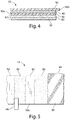
- the cathode composite may comprise a coating of cathode material 60 comprising iron disulfide (FeS 2 ) which is coated on at least one side of a substrate 65 as shown best in Figs. 4 and 5 .
- the cathode material 60 may also be coated on both sides of substrate 65.
- the cathode coating 60 is first coated as a wet cathode slurry onto at least one side of substrate 65 and then dried.
- the wet cathode slurry is coated on one side of substrate 65, dried.
- the same wet cathode slurry composition is then also coated on the opposite side of substrate 65 and subsequently dried, thus forming dry cathode coating 60 on both sides of substrate 65.
- the substrate or grid 65 is preferably an electrically conductive substrate, such as a sheet of aluminum, or stainless steel foil.
- the substrate 65 may be a continuous solid sheet without apertures or may be a sheet with apertures therein, for example, formed from expanded stainless steel foil or expanded aluminum foil.
- the anode 40 can be prepared from a solid sheet of lithium metal.
- the anode 40 is desirably formed of a continuous sheet of lithium metal (99.8 % pure).
- the anode 40 can be an alloy of lithium and an alloy metal, for example, an alloy of lithium and aluminum or lithium and calcium. In such case the alloy metal, is present in very small quantity, preferably less than 1 or 2 percent by weight of the lithium alloy. Upon cell discharge the lithium in the alloy thus functions electrochemically as pure lithium.
- the term "lithium or lithium metal” as used herein and in the claims is intended to include in its meaning such lithium alloy.
- the lithium sheet forming anode 40 does not require a substrate.
- the lithium anode 40 can be advantageously formed from an extruded sheet of lithium metal having a thickness of desirably between about 0.10 and 0.20 mm desirably between about 0.12 and 0.19 mm.
- the Li/FeS 2 wound cell is designed to have a balance of anode to cathode so that the anode active material is in excess.
- anode active material or “cathode active material” as used herein means the material in the anode or cathode, respectively, which engages in useful electrochemical discharge.
- the cell 10, representative of a wound Li/FeS 2 cylindrical cell configuration is balanced so that the theoretical capacity (mAmp-hrs) of the anode is greater than the theoretical capacity of the cathode.
- the ratio of the theoretical capacity of the anode to the theoretical capacity of the cathode is between 1.05 and 1.15.
- the theoretical capacity of the anode is the sum of the theoretical capacity (mAmp-hrs) of all the anode active materials in the anode.
- the theoretical capacity of the cathode is the sum of the theoretical capacity (mAmp-hrs) of all the cathode active materials in the cathode. It will be understood that the theoretical capacity of anode and cathode applies to only that portion of the anode and cathode layers which are facing each other with separator therebetween so that the active materials therein are capable of discharging.
- the theoretical capacity (mAmp-hrs) of the anode and theoretical capacity (mAmp-hrs) of the cathode, respectively are based on all the “anode active materials” and all the “cathode active materials”, respectively, usefully discharging. That is, it is based on 100 percent utilization of the anode active materials and 100 percent utilization of the cathode active materials, respectively, according to the normal discharge reactions occurring in the cell with respect to those active materials.
- the above indicated Li/FeS 2 cell balance (theoretical capacity (mAmp-hrs) of the anode greater than the theoretical capacity (mAmp-hrs) of the cathode) is made in conjunction with increasing the interfacial surface area for a wound cell AA size cell.
- the interfacial surface area between anode and cathode is increased to between 250 and 400 cm 2 , desirably at about 300 cm 2 .
- the interfacial area is the facing area between the anode and cathode with separator therebetween.
- the ratio of theoretical cathode capacity to interfacial area for Li/FeS 2 wound AA size cells is between about 9 and 17 mAmp-hrs/cm 2 preferably between about 11 and 15 mAmp-hrs/cm 2 . If each side of the substrate 65 is coated with cathode material 60 then the preceding ratios of between 11 and 15 mAmp-hrs/cm 2 are applied to each side.
- the Li/FeS 2 cell as in cell 10 has the following basic discharge reactions (one step mechanism):
- the Li/FeS 2 cylindrical cell 10 may be in the form of a primary (nonrechargeable) cell.
- the theoretical specific capacity (mAmp-hr/g) of FeS 2 can be calculated as follows based on a 4 electron transfer per molecule, wherein 2 electrons reduce Fe +2 to elemental iron Fe and 2 electrons reduce S -1 to 2S -2 forming Fe + 2Li 2 S.
- the molecular weight (M.W.) of FeS 2 is 119.97 and the M.W. of Li is 6.941.
- the charge q o of an electron is 1.602 x 10 -19 coulomb/electron.
- 1 coul 1 Amp-sec.
- Avogadro's number A 0 is 6.023 x 10 23 molecules per mol.
- a preferred cathode slurry mixture is presented in Table 1: Table I Cathode Composition Wet Slurry (wt.%) Binder 2.0 (Kraton G1651) Hydorcarbon Solvent 13.4 (ShellSol A100) (ShellSol OMS) 20.2 FeS 2 Powder 58.9 (Pyrox Red 325) Graphite 4.0 (Timrex KS6) Acetylene Carbon Black(Super P) 1.5 Total 100.0
- the Li/FeS 2 cell 10 internal configuration, apart from the difference in cathode composition, may be similar to the spirally wound configuration shown and described in U.S. patent 6,443,999 .
- the anode sheet 40 as shown in the figures comprises lithium metal and the cathode sheet 60 comprises iron disulfide (FeS 2 ) commonly known as "pyrite”.
- the cell is cylindrical as shown in the figures and is of AA (50 x 14 mm) size.
- a preferred shape of the cell casing (housing) 20 is cylindrical as shown in Fig. 1 .
- Casing 20 is preferably formed of nickel plated steel.
- the cell casing 20 ( Fig. 1 ) has a continuous cylindrical surface.
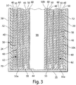
- the spiral wound electrode assembly 70 ( Fig. 3 ) comprising anode 40 and cathode composite 62 with separator 50 therebetween can be prepared by spirally winding a flat electrode composite 13 ( Figs. 4 and 5 ).
- Cathode composite 62 comprises a layer of cathode 60 comprising iron disulfide (FeS 2 ) coated onto metallic substrate 65 ( Fig. 4 ).
- the electrode composite 13 ( Figs. 4 and 5 ) can be made in the following manner:
- the cathode 60 comprising iron disulfide (FeS 2 ) powder dispersed therein can be initially prepared in the form of a wet slurry which is coated onto a side of conductive substrate sheet 65, preferably a sheet of aluminum or stainless steel which may a solid sheet with or without apertures therethrough, to form a cathode composite sheet 62 ( Fig. 4 ).
- Conventional roll coating techniques may be used to coat the wet slurry onto a side of conductive substrate 65 ( Figs. 4 and 5 ).
- an aluminum sheet 65 may be a solid sheet of aluminum without openings therethrough or may be a sheet of expanded or perforated aluminum foil with openings therethrough thus forming a grid or screen.
- the apertures in substrate sheet 65 may be the result of punching or piercing holes therein.
- the wet cathode slurry mixture having the composition shown above in Table 1 comprising iron disulfide (FeS 2 ), binder, conductive carbon and solvents is prepared by mixing the components shown in Table 1 until a homogeneous mixture is obtained.
- the above quantities of components can be scaled proportionally so that small or large batches of cathode slurry can be prepared.
- the wet cathode slurry thus preferably has the following composition: FeS 2 powder (58.9 wt.%); Binder, Kraton G1651 (2 wt.%); Graphite, Timrex KS6 (4.0 wt%), Acetylene Black, Super P (1.5 wt%), Hydrocarbon Solvents, ShellSol A100 (13.4 wt%) and ShellSol OMS (20.2 wt%).
- the wet slurry is then coated onto a side of the conductive substrate 65.
- the conductive substrate 65 with wet cathode slurry coated thereon is then dried in conventional convective oven (or in inert gas) to evaporate the solvents in the slurry, thereby forming a dry cathode coating 60 on one side of conductive substrate 65 ( Figs. 4 and 5 ).
- the process is repeated, if desired, to also coat the opposite side of conductive substrate 65 with the wet cathode slurry (Table 1).
- the wet cathode slurry on the opposite side of conductive substrate 65 can then be subjected to drying in a convective oven to evaporate solvents, thereby forming a dry cathode coating 60 also on the opposite side of conductive substrate 65.
- the drying of the wet cathode slurry coated on the metal substrate 65 is accomplished preferably by gradually adjusting or ramping up the oven temperature (to avoid cracking the coating) from an initial temperature of 40° C to a final temperature not to exceed 130° C for about 7-8 minutes or until the solvent has substantially all evaporated.
- the dry cathode coating 60 (whether applied to only one side or both sides of conductive substrate 65) is then subjected to calendering to compress the thickness of said dry cathode 60, thus forming the completed cathode composite 62 ( Figs. 4 and 5 ).
- the anode 40 can be prepared from a solid sheet of lithium metal.
- the anode 40 is desirably formed of a continuous sheet of lithium metal (99.8 % pure).
- the lithium metal in anode 40 may be alloyed with small amounts of other metal, for example aluminum, or calcium which typically comprises less than about 1 or 2 wt.%, and even up to about 5 wt.% of the lithium alloy.
- the lithium which forms the anode active material is preferably in the form of a thin foil. Upon cell discharge the lithium in the alloy thus functions electrochemically as pure lithium.
- the term "lithium or lithium metal" as used herein and in the claims is intended to include in its meaning such lithium alloy.
- the lithium sheet forming anode 40 does not require a substrate.
- the lithium anode 40 can be advantageously formed from an extruded sheet of lithium metal having a thickness of between about 0.09 and 0.20 mm desirably between about 0.09 and 0.19 mm for the spirally wound cell.
- Individual sheets of electrolyte permeable separator material 50 preferably of microporous polypropylene or polyethylene having a thickness of about 0.025 mm or less is inserted on each side of the lithium anode sheet 40 ( Figs. 4 and 5 ).
- the separator sheet may be microporous polyethylene or polypropylene of thickness about 0.016 mm.
- the microporous polypropylene desirably has a pore size between about 0.001 and 5 micron.
- the first (top) separator sheet 50 ( Fig. 4 ) can be designated the outer separator sheet and the second sheet 50 ( Fig. 4 ) can be designated the inner separator sheet.
- the cathode composite sheet 62 comprising cathode coating 60 on conductive substrate 65 is then placed against the inner separator sheet 50 to form the flat electrode composite 13 shown in Fig. 4 .
- the flat composite 13 ( Fig. 4 ) is spirally wound to form electrode spiral assembly 70 ( Fig. 3 ).
- the winding can be accomplished using a mandrel to grip an extended separator edge 50b ( Fig. 4 ) of electrode composite 13 and then spirally winding composite 13 clockwise to form wound electrode assembly 70 ( Fig.3 ).
- separator portion 50b appears within the core 98 of the wound electrode assembly 70 as shown in Figs. 2 and 3 .
- the bottom edges 50a of each revolution of the separator may be heat formed into a continuous membrane 55 as shown in Fig. 3 and taught in U.S. patent 6,443,999 .
- the electrode spiral 70 has separator material 50 between anode sheet 40 and cathode composite 62.
- the spirally wound electrode assembly 70 has a configuration ( Fig. 3 ) conforming to the shape of the casing body.
- the spirally wound electrode assembly 70 is inserted into the open end 30 of casing 20.
- the outer layer of the electrode spiral 70 comprises separator material 50 shown in Figs.
- An additional insulating layer 72 for example, a plastic film such as polyester tape, can desirably be placed over a of the outer separator layer 50, before the electrode composite 13 is wound.
- the spirally wound electrode 70 will have insulating layer 72 in contact with the inside surface of casing 20 ( Figs. 2 and 3 ) when the wound electrode composite is inserted into the casing.
- the inside surface of the casing 20 can be coated with electrically insulating material 72 before the wound electrode spiral 70 is inserted into the casing.
- a nonaqueous electrolyte mixture can then be added to the wound electrode spiral 70 after it is inserted into the cell casing 20.
- the desired nonaqueous electrolyte comprises a lithium salt LiCF 3 SO 3 (LiTFS) or Li(CF 3 SO 2 ) 2 N (LiTFSI) dissolved in an organic nonaqueous solvent.
- LiTFS lithium salt LiCF 3 SO 3
- LiTFSI Li(CF 3 SO 2 ) 2 N
- Such electrolyte may comprise a solution comprising 0.8 molar (0.8 mol/liter) concentration of LiTFSI salt dissolved in an organic solvent mixture comprising about 75 vol.% methyl acetate (MA), 20 vol.% propylene carbonate (PC), and 5 vol.% ethylene carbonate (EC). Elemental iodine in the amount comprising about 0.5 wt% of the electrolyte is desirably added to the electrolyte, as in commonly assigned U.S. patent application Ser. 11/516,534 . The electrolyte mixture is desirably added on the basis of about 0.4 gram electrolyte solution per gram FeS 2 for the spirally wound cell ( Fig. 2 ).
- Another desirable electrolyte is comprised of a mixture of Li(CF 3 SO 2 ) 2 N (LiTFSI) salt dissolved in a solvent mixture of 1,3 dioxolane (75 vol%) and sulfolane (25 vol %), as in commonly assigned U.S. patent application Ser. 11/494,244 .
- An end cap 18 forming the cell's positive terminal 17 may have a metal tab 25 (cathode tab) which can be welded on one of its sides to inside surface of end cap 18.
- Metal tab 25 is preferably of aluminum or aluminum alloy.
- a portion of the cathode substrate 65 may be flared along its top edge forming an extended portion 64 extending from the top of the wound spiral as shown in figure 2 .
- the flared cathode substrate portion 64 can be welded to the exposed side of metal tab 25 before the casing peripheral edge 22 is crimped around the end cap 18 with peripheral edge 85 of insulating disk 80 therebetween to close the cell's open end 30.
- End cap 18 desirably has a vent 19 which can contain a rupturable membrane designed to rupture and allow gas to escape if the gas pressure within the cell exceeds a predetermined level.
- Positive terminal 17 is desirably an integral portion of end cap 18.
- terminal 17 can be formed as the top of an end cap assembly of the type described in U.S. patent 5,879,832 , which assembly can be inserted into an opening in the surface of end cap 18 and then welded thereto.
- a metal tab 44 (anode tab), preferably of nickel, or nickel plated steel, can be pressed into a portion of the lithium metal anode 40.
- Anode tab 44 can be pressed into the lithium metal at any point within the spiral, for example, it can be pressed into the lithium metal at the outermost layer of the spiral as shown in Fig. 5 .
- Anode tab 44 can be embossed on one side forming a plurality of raised portions on the side of the tab to be pressed into the lithium.
- the opposite side of tab 44 can be welded to the inside surface of the casing either to the inside surface of the casing side wall 24 or more preferably to the inside surface of closed end 35 of casing 20 as shown in Fig. 3 .
- anode tab 44 it is preferable to weld anode tab 44 to the inside surface of the casing closed end 35, since this is readily accomplished by inserting an electrical spot welding probe (an elongated resistance welding electrode) into the cell core 98. Care should be taken to avoid contacting the welding probe to the separator starter tab 50b which is present along a portion of the outer boundary of cell core 98.
- an electrical spot welding probe an elongated resistance welding electrode
- the primary lithium cell 10 may optionally also be provided with a PTC (positive thermal coefficient) device 95 located under the end cap 18 and connected in series between the cathode 60 and end cap 18 ( Fig. 2 ).
- PTC positive thermal coefficient
- Such device protects the cell from discharge at a current drain higher than a predetermined level.
- an abnormally high current e.g., higher than about 6 to 8 Amp in a AA size cell for a prolonged period
- the resistance of the PTC device increases dramatically, thus shutting down the abnormally high drain.
- devices other than vent 19 and PTC device 95 may be employed to protect the cell from abusive use or discharge.
- the cathode capacity utilization in a Li/FeS 2 cell, such as representative wound cell 10, the cathode capacity utilization, particularly at high rate discharge, can be improved if the cathode is designed so that the ratio of cathode theoretical capacity (mAmp-hrs) to electrode interfacial area is reduced.
- the electrode interfacial area is the facing area between the anode 40 and cathode 60 with separator sheet 50 therebetween.
- the cathode utilization is the cathode efficiency as measured by the actual cathode capacity (mAmp-hrs) divided by the theoretical cathode capacity.
- the cathode in effect can be made thinner. This improves cathode utilization and increases cell voltage, particularly at high rate discharge conditions, for example, simulating use of the cell in powering digital cameras.
- a benefit of the improved Li/FeS 2 cell design resulting in higher cathode utilization and higher load voltage is that it becomes possible to employ lithium metal in the anode in amount so that the ratio of anode theoretical capacity (mAmp-hrs) to cathode theoretical capacity is greater than 1.0.
- the cell an AA size cell, is designed so that the ratio of cathode theoretical capacity to interfacial area is between about 9 and 17 mAmp-hrs/cm 2 , preferably between about 11 and 15 mAmp-hrs/cm 2 per side of substrate 65 onto which cathode 60 is coated. This in turn results in improved cathode utilization.
- Cathode theoretical capacity to interfacial area of between about 11 and 15 mAmp-hrs/cm 2 per side of substrate 65 corresponds to a loading of FeS 2 actives in the cathode of between about 0.0123 g/cm 2 /side and 0.0168 g/cm 2 /side, if FeS 2 is the only cathode active material in the cathode.
- the term "side” as used herein means each major side of substrate 65 onto which cathode 60 is coated.
- Designing the AA size cylindrical cell in this manner allows for inclusion of lithium metal in the anode in excess amount, that is, so that the ratio of anode theoretical capacity (mAmp-hrs) to cathode theoretical capacity is between 1.05 and 1.15.
- the total interfacial area (cm 2 ) for the cell can be increased compared to conventional cells, since at least the cathode layer 60 is made thinner because of the reduced cathode loading. That is, the cathode loading of cathode actives is desirably reduced to a theoretical cathode capacity to interfacial area ratio desirably between about 11 and 15 mAmp-hrs/cm 2 per side of substrate 65.
- a thinner separator sheet 50 is thus also desired in order not to reduce overall cell capacity.
- the inclusion of a thinner separator 50 in the cell design allows volume for the overall larger size separator area and greater amount of cathode foil substrate 65 needed because of the increased anode/cathode interfacial area. This enables use of thinner cathode and anode, without reducing the overall capacity of the cell.
- Test AA size cylindrical cells were made in accordance with the preceding description and are reference examples for background information. The test AA cells were all identical and made according to the following specifications.
- the cathode was coated in the form of a wet cathode slurry as earlier described herein onto both sides of an aluminum foil substrate 65.
- the aluminum foil had a thickness of about 15 micron.
- the wet cathode slurry was coated first on one side of foil substrate 65 and then dried as described herein.
- the wet cathode slurry was then coated onto the opposite side of substrate 65 and then dried.
- the dried cathode coatings 60 were then calendered to compress the coating thickness, thus forming a dry coating 60 on both sides of substrate 65 resulting in cathode composite 62.
- the cathode composite 62 had a total thickness of about 0.124 mm, which includes the thickness of substrate 65 (15 micron) and dry cathode coating 60 on both sides of substrate 65.
- the dry cathode coating 60 had the following composition: FeS 2 powder (Pyrox Red 325) 88.7 wt.%, acetylene black (Super P from Timcal Co.) 2.3 wt.%, graphite (Timrex KS6 from Timcal Co.) 6.0 wt.%, binder (Kraton G1651 from Kraton Polymers) 3.0 wt.%.
- the FeS 2 powder in the cathode had a loading of about 0.0144 g/cm 2 per side, which is equivalent to a theoretical capacity of about 12.86 mAmp-Hr/cm 2 per side.
- the cells had a total anode/cathode interfacial area of about 150 cm 2 per side of substrate 65 or 300 cm 2 total.
- the total FeS 2 loading capable of discharge in this example is the total weight of FeS 2 in both sides of substrate 65 facing the anode sheet 40 with separator sheet 50 therebetween.
- the anode 40 was formed from a sheet of lithium metal having sufficient thickness that the anode to cathode interfacial theoretical capacity ratio was about 1.02.
- the separator was formed of a sheet of microporous polyethylene having a thickness of about 0.016 mm.
- the electrolyte added to the cell comprised a mixture of Li(CF 3 SO 2 ) 2 N (LiTFSI) salt (0.8 mols/liter) dissolved in a solvent mixture of 1,3 dioxolane (75 vol%) and sulfolane (25 vol %), as in commonly assigned U.S. patent application Ser. 11/494,244 .
- Test AA cells After the Test AA cells were filled, they were predischarged slightly to a depth of discharge of about 3 percent of the cell's capacity and then stored at room temperature for 3 days. The cells were then subjected to the Digicam test described below.
- Test AA cells were discharged to a cutoff voltage of about 1.05 Volts using a digital camera discharge test (Digicam test).
- the digital camera test (Digicam test) consists of the following pulse test protocol wherein each test cell was drained by applying pulsed discharge cycles to the cell: Each cycle consists of both a 1.5 Watt pulse for 2 seconds followed immediately by a 0.65 Watt pulse for 28 seconds. These cycles are repeated 10 times followed by 55 minutes rest. Then the cycles are repeated until the cutoff voltage is reached. (The first pulse mimics the power of the digital camera required to take a picture and the second pulse mimics the power to view the picture taken.) The cycles are continued until a cutoff voltage of 1.05V is reached. The total number of the 1.5 Watt pulses required to reach these cutoff voltages were recorded. The average number of these pulses for the Test cells to a cutoff voltage of about 1.05V were about 644. This is considered to represent excellent performance for these Li/FeS 2 cells which were made in accordance with the invention. The discharge of the cell occurred smoothly without unintended delay or interruption. This indicated that there was no discontinuities developing on the lithium layer surface.
Landscapes
- Chemical & Material Sciences (AREA)
- Chemical Kinetics & Catalysis (AREA)
- Electrochemistry (AREA)
- General Chemical & Material Sciences (AREA)
- Engineering & Computer Science (AREA)
- Manufacturing & Machinery (AREA)
- Inorganic Chemistry (AREA)
- Materials Engineering (AREA)
- Battery Electrode And Active Subsutance (AREA)
- Primary Cells (AREA)
- Cell Separators (AREA)
Claims (4)
- Primäre elektrochemische Zelle, die umfasstein Gehäuse;einen positiven und einen negativen Anschluss;eine Anode, die mindestens eines von einem Lithiummetall und einer Lithiumlegierung als aktives Anodenmaterial umfasst;eine Kathode, die eine Beschichtung umfasst, die Eisen-Disulfid-Teilchen umfasst, die auf beiden Seiten eines Substrats aufgetragen sind, und wobei die Kathode ferner leitfähigen Kohlenstoff umfasst;wobei die Zelle ferner eine Trennfolie zwischen der Anode und der Kathode umfasst;wobei die Zelle so ausgeglichen ist, dass das Verhältnis, das durch die theoretische Kapazität (mAh) der Anode dividiert durch die theoretische Kapazität der Kathode (mAh) bestimmt ist, zwischen 1,05 und 1,15 liegt,wobei die Zelle eine zylindrische Zelle der Größe AA ist,wobei das Verhältnis der theoretischen Kapazität der Kathode zu der Grenzfläche zwischen der Anode und der Kathode zwischen 9 und 17 mAh pro cm2 pro Seite des Substrats ist, dadurch gekennzeichnet, dass:die Grenzfläche zwischen der Anode und der Kathode zwischen 250 und 400 cm2, vorzugsweise etwa 300 cm2, ist.
- Zelle nach Anspruch 1, wobei die Anode und die Kathode in gewickelter Konfiguration mit dem Separator dazwischen angeordnet sind.
- Zelle nach Anspruch 1, wobei das Verhältnis der theoretischen Kapazität der Kathode zur Grenzfläche zwischen der Anode und der Kathode zwischen 11 und 15 mAh pro cm2 pro Seite des Substrats ist.
- Zelle nach Anspruch 1, wobei der Separator aus mikroporösem Material gebildet ist, das Polyethylen oder Polypropylen umfasst, das eine Dicke zwischen 0,008 und 0,025 mm hat.
Priority Applications (2)
| Application Number | Priority Date | Filing Date | Title |
|---|---|---|---|
| EP16207601.2A EP3188284B1 (de) | 2007-12-05 | 2008-12-03 | Lithuimzelle |
| EP11181043A EP2398094A1 (de) | 2007-12-05 | 2008-12-03 | Lithiumzelle |
Applications Claiming Priority (2)
| Application Number | Priority Date | Filing Date | Title |
|---|---|---|---|
| US11/999,308 US8617743B2 (en) | 2007-12-05 | 2007-12-05 | Anode balanced lithium-iron disulfide primary cell |
| PCT/IB2008/055069 WO2009072066A1 (en) | 2007-12-05 | 2008-12-03 | Lithium cell |
Related Child Applications (3)
| Application Number | Title | Priority Date | Filing Date |
|---|---|---|---|
| EP11181043A Division-Into EP2398094A1 (de) | 2007-12-05 | 2008-12-03 | Lithiumzelle |
| EP16207601.2A Division EP3188284B1 (de) | 2007-12-05 | 2008-12-03 | Lithuimzelle |
| EP16207601.2A Division-Into EP3188284B1 (de) | 2007-12-05 | 2008-12-03 | Lithuimzelle |
Publications (2)
| Publication Number | Publication Date |
|---|---|
| EP2232614A1 EP2232614A1 (de) | 2010-09-29 |
| EP2232614B1 true EP2232614B1 (de) | 2017-02-22 |
Family
ID=40347910
Family Applications (3)
| Application Number | Title | Priority Date | Filing Date |
|---|---|---|---|
| EP08857978.4A Active EP2232614B1 (de) | 2007-12-05 | 2008-12-03 | Lithuimzelle |
| EP11181043A Withdrawn EP2398094A1 (de) | 2007-12-05 | 2008-12-03 | Lithiumzelle |
| EP16207601.2A Active EP3188284B1 (de) | 2007-12-05 | 2008-12-03 | Lithuimzelle |
Family Applications After (2)
| Application Number | Title | Priority Date | Filing Date |
|---|---|---|---|
| EP11181043A Withdrawn EP2398094A1 (de) | 2007-12-05 | 2008-12-03 | Lithiumzelle |
| EP16207601.2A Active EP3188284B1 (de) | 2007-12-05 | 2008-12-03 | Lithuimzelle |
Country Status (6)
| Country | Link |
|---|---|
| US (2) | US8617743B2 (de) |
| EP (3) | EP2232614B1 (de) |
| JP (1) | JP2011507154A (de) |
| CN (1) | CN101889362A (de) |
| BR (1) | BRPI0821042A2 (de) |
| WO (1) | WO2009072066A1 (de) |
Families Citing this family (30)
| Publication number | Priority date | Publication date | Assignee | Title |
|---|---|---|---|---|
| US8460826B2 (en) * | 2009-06-08 | 2013-06-11 | Eveready Battery Companym Inc. | Lithium-iron disulfide cell design |
| JP5730877B2 (ja) * | 2009-08-27 | 2015-06-10 | エバレデイ バツテリ カンパニー インコーポレーテツド | 高パイライト含有量及び低導電性添加剤を有するリチウム−二硫化鉄カソード調製 |
| US11081721B2 (en) | 2009-11-24 | 2021-08-03 | Duracell U.S. Operations, Inc. | Secondary electrochemical cells with separator and electrolyte combination |
| US8349493B2 (en) * | 2009-11-24 | 2013-01-08 | The Gillette Company | Electrochemical cells with improved separator and electrolyte |
| US20120315523A1 (en) * | 2011-06-09 | 2012-12-13 | Michael Pozin | Electrochemical cells with improved spiral-wound electrode assembly |
| CN102738418B (zh) * | 2012-06-30 | 2015-08-12 | 惠州亿纬锂能股份有限公司 | 方形锂-二硫化亚铁电池及其制备方法 |
| US8920969B2 (en) | 2012-12-05 | 2014-12-30 | The Gillette Company | Alkaline electrochemical cells with separator and electrolyte combination |
| US10008748B2 (en) | 2012-12-05 | 2018-06-26 | Duracell U.S. Operations, Inc. | Alkaline electrochemical cells with separator and electrolyte combination |
| US9551758B2 (en) | 2012-12-27 | 2017-01-24 | Duracell U.S. Operations, Inc. | Remote sensing of remaining battery capacity using on-battery circuitry |
| US9478850B2 (en) | 2013-05-23 | 2016-10-25 | Duracell U.S. Operations, Inc. | Omni-directional antenna for a cylindrical body |
| US9726763B2 (en) | 2013-06-21 | 2017-08-08 | Duracell U.S. Operations, Inc. | Systems and methods for remotely determining a battery characteristic |
| US9882250B2 (en) | 2014-05-30 | 2018-01-30 | Duracell U.S. Operations, Inc. | Indicator circuit decoupled from a ground plane |
| US10297875B2 (en) | 2015-09-01 | 2019-05-21 | Duracell U.S. Operations, Inc. | Battery including an on-cell indicator |
| US20170173439A1 (en) * | 2015-12-18 | 2017-06-22 | Gridiron Innovations LLC | Football Training, Animation Techniques, and Statistical Analysis |
| USD899355S1 (en) | 2016-08-15 | 2020-10-20 | Milwaukee Electric Tool Corporation | Battery |
| US10847780B2 (en) * | 2016-09-16 | 2020-11-24 | Pacesetter, Inc. | Battery electrode and methods of making |
| PL3526827T3 (pl) | 2016-10-14 | 2022-11-28 | Milwaukee Electric Tool Corporation | Pakiet akumulatorów |
| US10483634B2 (en) | 2016-11-01 | 2019-11-19 | Duracell U.S. Operations, Inc. | Positive battery terminal antenna ground plane |
| US10608293B2 (en) | 2016-11-01 | 2020-03-31 | Duracell U.S. Operations, Inc. | Dual sided reusable battery indicator |
| US11024891B2 (en) | 2016-11-01 | 2021-06-01 | Duracell U.S. Operations, Inc. | Reusable battery indicator with lock and key mechanism |
| US10818979B2 (en) | 2016-11-01 | 2020-10-27 | Duracell U.S. Operations, Inc. | Single sided reusable battery indicator |
| US10151802B2 (en) | 2016-11-01 | 2018-12-11 | Duracell U.S. Operations, Inc. | Reusable battery indicator with electrical lock and key |
| JP6986710B2 (ja) * | 2018-07-23 | 2021-12-22 | パナソニックIpマネジメント株式会社 | リチウム一次電池およびスマートメータ |
| US12087975B2 (en) | 2018-11-07 | 2024-09-10 | Panasonic Intellectual Property Management Co., Ltd. | Lithium primary battery |
| USD911926S1 (en) * | 2019-03-13 | 2021-03-02 | Ningbo Roca Superior Products E-Commerce Co., Ltd | Rechargeable battery |
| USD929315S1 (en) * | 2019-03-15 | 2021-08-31 | The Coleman Company, Inc. | Interchangeable battery |
| JP7211246B2 (ja) * | 2019-04-22 | 2023-01-24 | トヨタ自動車株式会社 | 電池の製造方法および電池 |
| US11837754B2 (en) | 2020-12-30 | 2023-12-05 | Duracell U.S. Operations, Inc. | Magnetic battery cell connection mechanism |
| JP7364605B2 (ja) * | 2021-01-04 | 2023-10-18 | プライムアースEvエナジー株式会社 | 電池状態判定方法及び電池状態判定装置 |
| CN113745751B (zh) * | 2021-08-31 | 2023-07-25 | 远景动力技术(江苏)有限公司 | 锂离子电池隔膜及其制备方法与应用 |
Citations (1)
| Publication number | Priority date | Publication date | Assignee | Title |
|---|---|---|---|---|
| US8859145B2 (en) * | 2008-05-23 | 2014-10-14 | The Gillette Company | Method of preparing cathode containing iron disulfide for a lithium cell |
Family Cites Families (33)
| Publication number | Priority date | Publication date | Assignee | Title |
|---|---|---|---|---|
| US4163829A (en) * | 1977-11-14 | 1979-08-07 | Union Carbide Corporation | Metallic reducing additives for solid cathodes for use in nonaqueous cells |
| JPS61227365A (ja) * | 1985-03-30 | 1986-10-09 | Sony Ebaredei Kk | 有機電解質電池 |
| US4707421A (en) | 1985-05-02 | 1987-11-17 | Duracell Inc. | Spirally wound electrochemical cells |
| JPS63168973A (ja) * | 1986-12-29 | 1988-07-12 | Kuraray Co Ltd | 電池 |
| JP2674793B2 (ja) * | 1988-08-31 | 1997-11-12 | ソニー 株式会社 | 非水電解液電池 |
| US4952330A (en) * | 1989-05-25 | 1990-08-28 | Eveready Battery Company, Inc. | Nonaqueous electrolyte |
| CA2072488C (en) * | 1991-08-13 | 2002-10-01 | Andrew Webber | Nonaqueous electrolytes |
| US5290414A (en) * | 1992-05-15 | 1994-03-01 | Eveready Battery Company, Inc. | Separator/electrolyte combination for a nonaqueous cell |
| US5229227A (en) * | 1992-07-23 | 1993-07-20 | Eveready Battery Company Inc. | Low flammability nonaqueous electrolytes |
| US5514491A (en) | 1993-12-02 | 1996-05-07 | Eveready Battery Company, Inc. | Nonaqueous cell having a lithium iodide-ether electrolyte |
| US5432030A (en) * | 1993-12-02 | 1995-07-11 | Eveready Battery Company, Inc. | Li/FeS2 cell employing a solvent mixture of diox, DME and 3ME20X with a lithium-based solute |
| US5698176A (en) * | 1995-06-07 | 1997-12-16 | Duracell, Inc. | Manganese dioxide for lithium batteries |
| US5879832A (en) | 1996-10-02 | 1999-03-09 | Duracell Inc. | Current interrupter for electrochemical cells |
| US6443999B1 (en) | 2000-03-16 | 2002-09-03 | The Gillette Company | Lithium cell with heat formed separator |
| KR100388906B1 (ko) * | 2000-09-29 | 2003-06-25 | 삼성에스디아이 주식회사 | 리튬 2차 전지 |
| US6585881B2 (en) | 2001-02-20 | 2003-07-01 | The Gillette Company | Process for manufacture and improved manganese dioxide for electrochemical cells |
| US20050112462A1 (en) * | 2003-11-21 | 2005-05-26 | Marple Jack W. | High discharge capacity lithium battery |
| US7314681B2 (en) * | 2002-02-15 | 2008-01-01 | Eveready Battery Company, Inc. | Cylindrical alkaline cells with increased discharge performance |
| US6849360B2 (en) * | 2002-06-05 | 2005-02-01 | Eveready Battery Company, Inc. | Nonaqueous electrochemical cell with improved energy density |
| TWI251951B (en) * | 2003-09-19 | 2006-03-21 | Lg Chemical Ltd | Nonaqueous lithium secondary battery with cyclability and/or high temperature safety improved |
| US8124274B2 (en) | 2003-11-21 | 2012-02-28 | Eveready Battery Company, Inc. | High discharge capacity lithium battery |
| US20050233214A1 (en) | 2003-11-21 | 2005-10-20 | Marple Jack W | High discharge capacity lithium battery |
| US7833647B2 (en) | 2004-04-28 | 2010-11-16 | Eveready Battery Company, Inc. | Closure vent seal and assembly |
| US7687189B2 (en) | 2004-04-28 | 2010-03-30 | Eveready Battery Company, Inc. | Housing for a sealed electrochemical battery cell |
| US20060046154A1 (en) | 2004-08-27 | 2006-03-02 | Eveready Battery Company, Inc. | Low temperature Li/FeS2 battery |
| US7510808B2 (en) * | 2004-08-27 | 2009-03-31 | Eveready Battery Company, Inc. | Low temperature Li/FeS2 battery |
| US20060046153A1 (en) | 2004-08-27 | 2006-03-02 | Andrew Webber | Low temperature Li/FeS2 battery |
| KR100777126B1 (ko) * | 2005-07-13 | 2007-11-29 | 주식회사 엘지화학 | 첨가제 담지 서방성 캡슐을 포함하고 있는 리튬 이차전지 |
| JP4962755B2 (ja) | 2005-11-30 | 2012-06-27 | ソニー株式会社 | 電池 |
| JP4539584B2 (ja) | 2006-02-24 | 2010-09-08 | ソニー株式会社 | リチウム/二硫化鉄一次電池 |
| US7595133B2 (en) * | 2006-07-01 | 2009-09-29 | The Gillette Company | Lithium cell |
| US20080057403A1 (en) * | 2006-09-06 | 2008-03-06 | Issaev Nikolai N | Lithium cell |
| US7981550B2 (en) * | 2007-03-19 | 2011-07-19 | The Gillette Company | Lithium cell |
-
2007
- 2007-12-05 US US11/999,308 patent/US8617743B2/en active Active
-
2008
- 2008-12-03 EP EP08857978.4A patent/EP2232614B1/de active Active
- 2008-12-03 EP EP11181043A patent/EP2398094A1/de not_active Withdrawn
- 2008-12-03 CN CN200880119412XA patent/CN101889362A/zh active Pending
- 2008-12-03 BR BRPI0821042-0A patent/BRPI0821042A2/pt not_active IP Right Cessation
- 2008-12-03 WO PCT/IB2008/055069 patent/WO2009072066A1/en not_active Ceased
- 2008-12-03 EP EP16207601.2A patent/EP3188284B1/de active Active
- 2008-12-03 JP JP2010536570A patent/JP2011507154A/ja not_active Withdrawn
-
2013
- 2013-10-31 US US14/068,129 patent/US8790828B2/en active Active
Patent Citations (1)
| Publication number | Priority date | Publication date | Assignee | Title |
|---|---|---|---|---|
| US8859145B2 (en) * | 2008-05-23 | 2014-10-14 | The Gillette Company | Method of preparing cathode containing iron disulfide for a lithium cell |
Also Published As
| Publication number | Publication date |
|---|---|
| US8790828B2 (en) | 2014-07-29 |
| WO2009072066A1 (en) | 2009-06-11 |
| EP3188284A1 (de) | 2017-07-05 |
| US20140079972A1 (en) | 2014-03-20 |
| US8617743B2 (en) | 2013-12-31 |
| BRPI0821042A2 (pt) | 2015-06-16 |
| JP2011507154A (ja) | 2011-03-03 |
| CN101889362A (zh) | 2010-11-17 |
| EP2398094A1 (de) | 2011-12-21 |
| US20090148756A1 (en) | 2009-06-11 |
| EP2232614A1 (de) | 2010-09-29 |
| EP3188284B1 (de) | 2018-09-12 |
Similar Documents
| Publication | Publication Date | Title |
|---|---|---|
| EP2232614B1 (de) | Lithuimzelle | |
| US8062788B2 (en) | Lithium cell | |
| EP2232615B1 (de) | Lithiumzelle | |
| US8197973B2 (en) | Lithium cell | |
| US20090214950A1 (en) | Lithium cell | |
| US20100203370A1 (en) | Lithium cell with iron disulfide cathode | |
| EP2243180B1 (de) | Lithiumzelle | |
| WO2009129213A1 (en) | Lithium cell with cathode including iron disulfide and iron sulfide | |
| EP2074673A2 (de) | Lithiumzelle | |
| WO2009012291A1 (en) | Lithium cell | |
| US20090074953A1 (en) | Lithium cell cathode | |
| US20090317725A1 (en) | Lithium cell with cathode containing iron disulfide | |
| US20080318123A1 (en) | Lithium cell |
Legal Events
| Date | Code | Title | Description |
|---|---|---|---|
| PUAI | Public reference made under article 153(3) epc to a published international application that has entered the european phase |
Free format text: ORIGINAL CODE: 0009012 |
|
| 17P | Request for examination filed |
Effective date: 20100615 |
|
| AK | Designated contracting states |
Kind code of ref document: A1 Designated state(s): AT BE BG CH CY CZ DE DK EE ES FI FR GB GR HR HU IE IS IT LI LT LU LV MC MT NL NO PL PT RO SE SI SK TR |
|
| AX | Request for extension of the european patent |
Extension state: AL BA MK RS |
|
| DAX | Request for extension of the european patent (deleted) | ||
| 17Q | First examination report despatched |
Effective date: 20110318 |
|
| RAP1 | Party data changed (applicant data changed or rights of an application transferred) |
Owner name: THE GILLETTE COMPANY |
|
| RAP1 | Party data changed (applicant data changed or rights of an application transferred) |
Owner name: DURACELL U.S. OPERATIONS, INC. |
|
| GRAP | Despatch of communication of intention to grant a patent |
Free format text: ORIGINAL CODE: EPIDOSNIGR1 |
|
| RIC1 | Information provided on ipc code assigned before grant |
Ipc: H01M 6/50 20060101ALI20160822BHEP Ipc: H01M 2/16 20060101ALN20160822BHEP Ipc: H01M 2/02 20060101ALN20160822BHEP Ipc: H01M 4/38 20060101ALI20160822BHEP Ipc: H01M 4/02 20060101ALN20160822BHEP Ipc: H01M 6/10 20060101ALN20160822BHEP Ipc: H01M 4/04 20060101ALN20160822BHEP Ipc: H01M 6/16 20060101ALI20160822BHEP Ipc: H01M 4/12 20060101AFI20160822BHEP Ipc: H01M 4/58 20060101ALI20160822BHEP |
|
| RIC1 | Information provided on ipc code assigned before grant |
Ipc: H01M 4/38 20060101ALI20160906BHEP Ipc: H01M 2/16 20060101AFI20160906BHEP Ipc: H01M 4/06 20060101ALI20160906BHEP Ipc: H01M 6/16 20060101ALI20160906BHEP Ipc: H01M 4/04 20060101ALN20160906BHEP Ipc: H01M 4/58 20060101ALI20160906BHEP Ipc: H01M 2/02 20060101ALN20160906BHEP Ipc: H01M 4/40 20060101ALI20160906BHEP Ipc: H01M 6/50 20060101ALI20160906BHEP Ipc: H01M 4/02 20060101ALN20160906BHEP |
|
| INTG | Intention to grant announced |
Effective date: 20160920 |
|
| GRAS | Grant fee paid |
Free format text: ORIGINAL CODE: EPIDOSNIGR3 |
|
| STAA | Information on the status of an ep patent application or granted ep patent |
Free format text: STATUS: GRANT OF PATENT IS INTENDED |
|
| GRAJ | Information related to disapproval of communication of intention to grant by the applicant or resumption of examination proceedings by the epo deleted |
Free format text: ORIGINAL CODE: EPIDOSDIGR1 |
|
| GRAL | Information related to payment of fee for publishing/printing deleted |
Free format text: ORIGINAL CODE: EPIDOSDIGR3 |
|
| REG | Reference to a national code |
Ref country code: DE Ref legal event code: R079 Ref document number: 602008048864 Country of ref document: DE Free format text: PREVIOUS MAIN CLASS: H01M0004120000 Ipc: H01M0002160000 |
|
| STAA | Information on the status of an ep patent application or granted ep patent |
Free format text: STATUS: EXAMINATION IS IN PROGRESS |
|
| GRAR | Information related to intention to grant a patent recorded |
Free format text: ORIGINAL CODE: EPIDOSNIGR71 |
|
| STAA | Information on the status of an ep patent application or granted ep patent |
Free format text: STATUS: GRANT OF PATENT IS INTENDED |
|
| GRAA | (expected) grant |
Free format text: ORIGINAL CODE: 0009210 |
|
| STAA | Information on the status of an ep patent application or granted ep patent |
Free format text: STATUS: THE PATENT HAS BEEN GRANTED |
|
| INTC | Intention to grant announced (deleted) | ||
| INTG | Intention to grant announced |
Effective date: 20170112 |
|
| RIC1 | Information provided on ipc code assigned before grant |
Ipc: H01M 4/04 20060101ALN20170106BHEP Ipc: H01M 4/06 20060101ALI20170106BHEP Ipc: H01M 4/38 20060101ALI20170106BHEP Ipc: H01M 2/16 20060101AFI20170106BHEP Ipc: H01M 6/16 20060101ALI20170106BHEP Ipc: H01M 4/40 20060101ALI20170106BHEP Ipc: H01M 6/50 20060101ALI20170106BHEP Ipc: H01M 4/02 20060101ALN20170106BHEP Ipc: H01M 2/02 20060101ALN20170106BHEP Ipc: H01M 4/58 20100101ALI20170106BHEP |
|
| AK | Designated contracting states |
Kind code of ref document: B1 Designated state(s): AT BE BG CH CY CZ DE DK EE ES FI FR GB GR HR HU IE IS IT LI LT LU LV MC MT NL NO PL PT RO SE SI SK TR |
|
| REG | Reference to a national code |
Ref country code: GB Ref legal event code: FG4D |
|
| REG | Reference to a national code |
Ref country code: CH Ref legal event code: EP |
|
| REG | Reference to a national code |
Ref country code: AT Ref legal event code: REF Ref document number: 869899 Country of ref document: AT Kind code of ref document: T Effective date: 20170315 |
|
| REG | Reference to a national code |
Ref country code: IE Ref legal event code: FG4D |
|
| REG | Reference to a national code |
Ref country code: DE Ref legal event code: R096 Ref document number: 602008048864 Country of ref document: DE |
|
| REG | Reference to a national code |
Ref country code: LT Ref legal event code: MG4D |
|
| REG | Reference to a national code |
Ref country code: NL Ref legal event code: MP Effective date: 20170222 |
|
| REG | Reference to a national code |
Ref country code: AT Ref legal event code: MK05 Ref document number: 869899 Country of ref document: AT Kind code of ref document: T Effective date: 20170222 |
|
| PG25 | Lapsed in a contracting state [announced via postgrant information from national office to epo] |
Ref country code: HR Free format text: LAPSE BECAUSE OF FAILURE TO SUBMIT A TRANSLATION OF THE DESCRIPTION OR TO PAY THE FEE WITHIN THE PRESCRIBED TIME-LIMIT Effective date: 20170222 Ref country code: FI Free format text: LAPSE BECAUSE OF FAILURE TO SUBMIT A TRANSLATION OF THE DESCRIPTION OR TO PAY THE FEE WITHIN THE PRESCRIBED TIME-LIMIT Effective date: 20170222 Ref country code: GR Free format text: LAPSE BECAUSE OF FAILURE TO SUBMIT A TRANSLATION OF THE DESCRIPTION OR TO PAY THE FEE WITHIN THE PRESCRIBED TIME-LIMIT Effective date: 20170523 Ref country code: LT Free format text: LAPSE BECAUSE OF FAILURE TO SUBMIT A TRANSLATION OF THE DESCRIPTION OR TO PAY THE FEE WITHIN THE PRESCRIBED TIME-LIMIT Effective date: 20170222 Ref country code: NO Free format text: LAPSE BECAUSE OF FAILURE TO SUBMIT A TRANSLATION OF THE DESCRIPTION OR TO PAY THE FEE WITHIN THE PRESCRIBED TIME-LIMIT Effective date: 20170522 |
|
| PG25 | Lapsed in a contracting state [announced via postgrant information from national office to epo] |
Ref country code: AT Free format text: LAPSE BECAUSE OF FAILURE TO SUBMIT A TRANSLATION OF THE DESCRIPTION OR TO PAY THE FEE WITHIN THE PRESCRIBED TIME-LIMIT Effective date: 20170222 Ref country code: SE Free format text: LAPSE BECAUSE OF FAILURE TO SUBMIT A TRANSLATION OF THE DESCRIPTION OR TO PAY THE FEE WITHIN THE PRESCRIBED TIME-LIMIT Effective date: 20170222 Ref country code: PT Free format text: LAPSE BECAUSE OF FAILURE TO SUBMIT A TRANSLATION OF THE DESCRIPTION OR TO PAY THE FEE WITHIN THE PRESCRIBED TIME-LIMIT Effective date: 20170622 Ref country code: NL Free format text: LAPSE BECAUSE OF FAILURE TO SUBMIT A TRANSLATION OF THE DESCRIPTION OR TO PAY THE FEE WITHIN THE PRESCRIBED TIME-LIMIT Effective date: 20170222 Ref country code: LV Free format text: LAPSE BECAUSE OF FAILURE TO SUBMIT A TRANSLATION OF THE DESCRIPTION OR TO PAY THE FEE WITHIN THE PRESCRIBED TIME-LIMIT Effective date: 20170222 Ref country code: BG Free format text: LAPSE BECAUSE OF FAILURE TO SUBMIT A TRANSLATION OF THE DESCRIPTION OR TO PAY THE FEE WITHIN THE PRESCRIBED TIME-LIMIT Effective date: 20170522 Ref country code: ES Free format text: LAPSE BECAUSE OF FAILURE TO SUBMIT A TRANSLATION OF THE DESCRIPTION OR TO PAY THE FEE WITHIN THE PRESCRIBED TIME-LIMIT Effective date: 20170222 |
|
| REG | Reference to a national code |
Ref country code: FR Ref legal event code: PLFP Year of fee payment: 10 |
|
| PG25 | Lapsed in a contracting state [announced via postgrant information from national office to epo] |
Ref country code: RO Free format text: LAPSE BECAUSE OF FAILURE TO SUBMIT A TRANSLATION OF THE DESCRIPTION OR TO PAY THE FEE WITHIN THE PRESCRIBED TIME-LIMIT Effective date: 20170222 Ref country code: CZ Free format text: LAPSE BECAUSE OF FAILURE TO SUBMIT A TRANSLATION OF THE DESCRIPTION OR TO PAY THE FEE WITHIN THE PRESCRIBED TIME-LIMIT Effective date: 20170222 Ref country code: SK Free format text: LAPSE BECAUSE OF FAILURE TO SUBMIT A TRANSLATION OF THE DESCRIPTION OR TO PAY THE FEE WITHIN THE PRESCRIBED TIME-LIMIT Effective date: 20170222 Ref country code: IT Free format text: LAPSE BECAUSE OF FAILURE TO SUBMIT A TRANSLATION OF THE DESCRIPTION OR TO PAY THE FEE WITHIN THE PRESCRIBED TIME-LIMIT Effective date: 20170222 Ref country code: EE Free format text: LAPSE BECAUSE OF FAILURE TO SUBMIT A TRANSLATION OF THE DESCRIPTION OR TO PAY THE FEE WITHIN THE PRESCRIBED TIME-LIMIT Effective date: 20170222 |
|
| REG | Reference to a national code |
Ref country code: DE Ref legal event code: R097 Ref document number: 602008048864 Country of ref document: DE |
|
| PG25 | Lapsed in a contracting state [announced via postgrant information from national office to epo] |
Ref country code: DK Free format text: LAPSE BECAUSE OF FAILURE TO SUBMIT A TRANSLATION OF THE DESCRIPTION OR TO PAY THE FEE WITHIN THE PRESCRIBED TIME-LIMIT Effective date: 20170222 Ref country code: PL Free format text: LAPSE BECAUSE OF FAILURE TO SUBMIT A TRANSLATION OF THE DESCRIPTION OR TO PAY THE FEE WITHIN THE PRESCRIBED TIME-LIMIT Effective date: 20170222 |
|
| PLBE | No opposition filed within time limit |
Free format text: ORIGINAL CODE: 0009261 |
|
| STAA | Information on the status of an ep patent application or granted ep patent |
Free format text: STATUS: NO OPPOSITION FILED WITHIN TIME LIMIT |
|
| 26N | No opposition filed |
Effective date: 20171123 |
|
| PG25 | Lapsed in a contracting state [announced via postgrant information from national office to epo] |
Ref country code: SI Free format text: LAPSE BECAUSE OF FAILURE TO SUBMIT A TRANSLATION OF THE DESCRIPTION OR TO PAY THE FEE WITHIN THE PRESCRIBED TIME-LIMIT Effective date: 20170222 |
|
| REG | Reference to a national code |
Ref country code: CH Ref legal event code: PL |
|
| REG | Reference to a national code |
Ref country code: IE Ref legal event code: MM4A |
|
| PG25 | Lapsed in a contracting state [announced via postgrant information from national office to epo] |
Ref country code: MT Free format text: LAPSE BECAUSE OF NON-PAYMENT OF DUE FEES Effective date: 20171203 Ref country code: LU Free format text: LAPSE BECAUSE OF NON-PAYMENT OF DUE FEES Effective date: 20171203 |
|
| REG | Reference to a national code |
Ref country code: FR Ref legal event code: PLFP Year of fee payment: 11 |
|
| PG25 | Lapsed in a contracting state [announced via postgrant information from national office to epo] |
Ref country code: IE Free format text: LAPSE BECAUSE OF NON-PAYMENT OF DUE FEES Effective date: 20171203 |
|
| PG25 | Lapsed in a contracting state [announced via postgrant information from national office to epo] |
Ref country code: CH Free format text: LAPSE BECAUSE OF NON-PAYMENT OF DUE FEES Effective date: 20171231 Ref country code: LI Free format text: LAPSE BECAUSE OF NON-PAYMENT OF DUE FEES Effective date: 20171231 |
|
| PG25 | Lapsed in a contracting state [announced via postgrant information from national office to epo] |
Ref country code: MC Free format text: LAPSE BECAUSE OF FAILURE TO SUBMIT A TRANSLATION OF THE DESCRIPTION OR TO PAY THE FEE WITHIN THE PRESCRIBED TIME-LIMIT Effective date: 20170222 Ref country code: HU Free format text: LAPSE BECAUSE OF FAILURE TO SUBMIT A TRANSLATION OF THE DESCRIPTION OR TO PAY THE FEE WITHIN THE PRESCRIBED TIME-LIMIT; INVALID AB INITIO Effective date: 20081203 |
|
| PG25 | Lapsed in a contracting state [announced via postgrant information from national office to epo] |
Ref country code: CY Free format text: LAPSE BECAUSE OF NON-PAYMENT OF DUE FEES Effective date: 20170222 |
|
| PGFP | Annual fee paid to national office [announced via postgrant information from national office to epo] |
Ref country code: FR Payment date: 20191014 Year of fee payment: 12 Ref country code: BE Payment date: 20191118 Year of fee payment: 12 |
|
| PG25 | Lapsed in a contracting state [announced via postgrant information from national office to epo] |
Ref country code: TR Free format text: LAPSE BECAUSE OF FAILURE TO SUBMIT A TRANSLATION OF THE DESCRIPTION OR TO PAY THE FEE WITHIN THE PRESCRIBED TIME-LIMIT Effective date: 20170222 |
|
| PG25 | Lapsed in a contracting state [announced via postgrant information from national office to epo] |
Ref country code: IS Free format text: LAPSE BECAUSE OF FAILURE TO SUBMIT A TRANSLATION OF THE DESCRIPTION OR TO PAY THE FEE WITHIN THE PRESCRIBED TIME-LIMIT Effective date: 20170622 |
|
| REG | Reference to a national code |
Ref country code: DE Ref legal event code: R079 Ref document number: 602008048864 Country of ref document: DE Free format text: PREVIOUS MAIN CLASS: H01M0002160000 Ipc: H01M0050409000 |
|
| REG | Reference to a national code |
Ref country code: BE Ref legal event code: MM Effective date: 20201231 |
|
| PG25 | Lapsed in a contracting state [announced via postgrant information from national office to epo] |
Ref country code: FR Free format text: LAPSE BECAUSE OF NON-PAYMENT OF DUE FEES Effective date: 20201231 |
|
| PG25 | Lapsed in a contracting state [announced via postgrant information from national office to epo] |
Ref country code: BE Free format text: LAPSE BECAUSE OF NON-PAYMENT OF DUE FEES Effective date: 20201231 |
|
| P01 | Opt-out of the competence of the unified patent court (upc) registered |
Effective date: 20230526 |
|
| PGFP | Annual fee paid to national office [announced via postgrant information from national office to epo] |
Ref country code: DE Payment date: 20250930 Year of fee payment: 18 |
|
| PGFP | Annual fee paid to national office [announced via postgrant information from national office to epo] |
Ref country code: GB Payment date: 20251001 Year of fee payment: 18 |