EP2232004B1 - SammelVORRICHTUNG UND VERFAHREN ZU IHRER ANWENDUNG - Google Patents
SammelVORRICHTUNG UND VERFAHREN ZU IHRER ANWENDUNG Download PDFInfo
- Publication number
- EP2232004B1 EP2232004B1 EP08861254A EP08861254A EP2232004B1 EP 2232004 B1 EP2232004 B1 EP 2232004B1 EP 08861254 A EP08861254 A EP 08861254A EP 08861254 A EP08861254 A EP 08861254A EP 2232004 B1 EP2232004 B1 EP 2232004B1
- Authority
- EP
- European Patent Office
- Prior art keywords
- collecting device
- fluid
- accordance
- solids material
- inlet portion
- Prior art date
- Legal status (The legal status is an assumption and is not a legal conclusion. Google has not performed a legal analysis and makes no representation as to the accuracy of the status listed.)
- Not-in-force
Links
- 238000000034 method Methods 0.000 title claims abstract description 13
- 239000012530 fluid Substances 0.000 claims abstract description 40
- 239000000463 material Substances 0.000 claims abstract description 39
- 239000007787 solid Substances 0.000 claims abstract description 30
- 238000009434 installation Methods 0.000 claims abstract description 6
- 230000035699 permeability Effects 0.000 claims description 12
- 239000011230 binding agent Substances 0.000 claims description 8
- 239000003795 chemical substances by application Substances 0.000 claims description 5
- 238000005086 pumping Methods 0.000 claims description 4
- 230000001376 precipitating effect Effects 0.000 claims description 3
- 238000001556 precipitation Methods 0.000 claims description 2
- 239000002245 particle Substances 0.000 description 9
- 239000011236 particulate material Substances 0.000 description 6
- XLYOFNOQVPJJNP-UHFFFAOYSA-N water Substances O XLYOFNOQVPJJNP-UHFFFAOYSA-N 0.000 description 6
- 238000005520 cutting process Methods 0.000 description 4
- 238000009826 distribution Methods 0.000 description 3
- 238000005553 drilling Methods 0.000 description 3
- 239000002699 waste material Substances 0.000 description 3
- 238000004891 communication Methods 0.000 description 2
- 230000000694 effects Effects 0.000 description 2
- 239000004744 fabric Substances 0.000 description 2
- 238000007667 floating Methods 0.000 description 2
- 239000007788 liquid Substances 0.000 description 2
- 239000004576 sand Substances 0.000 description 2
- 238000004062 sedimentation Methods 0.000 description 2
- 239000000126 substance Substances 0.000 description 2
- 238000004140 cleaning Methods 0.000 description 1
- 238000010276 construction Methods 0.000 description 1
- 230000004069 differentiation Effects 0.000 description 1
- 239000007791 liquid phase Substances 0.000 description 1
- 238000004519 manufacturing process Methods 0.000 description 1
- 238000005065 mining Methods 0.000 description 1
- 239000003208 petroleum Substances 0.000 description 1
- 239000011148 porous material Substances 0.000 description 1
- 230000003014 reinforcing effect Effects 0.000 description 1
- 230000000717 retained effect Effects 0.000 description 1
- 238000000926 separation method Methods 0.000 description 1
- 238000003892 spreading Methods 0.000 description 1
- 238000011144 upstream manufacturing Methods 0.000 description 1
Images


Classifications
-
- E—FIXED CONSTRUCTIONS
- E21—EARTH OR ROCK DRILLING; MINING
- E21B—EARTH OR ROCK DRILLING; OBTAINING OIL, GAS, WATER, SOLUBLE OR MELTABLE MATERIALS OR A SLURRY OF MINERALS FROM WELLS
- E21B21/00—Methods or apparatus for flushing boreholes, e.g. by use of exhaust air from motor
- E21B21/06—Arrangements for treating drilling fluids outside the borehole
- E21B21/063—Arrangements for treating drilling fluids outside the borehole by separating components
- E21B21/065—Separating solids from drilling fluids
- E21B21/066—Separating solids from drilling fluids with further treatment of the solids, e.g. for disposal
-
- E—FIXED CONSTRUCTIONS
- E02—HYDRAULIC ENGINEERING; FOUNDATIONS; SOIL SHIFTING
- E02F—DREDGING; SOIL-SHIFTING
- E02F7/00—Equipment for conveying or separating excavated material
-
- E—FIXED CONSTRUCTIONS
- E02—HYDRAULIC ENGINEERING; FOUNDATIONS; SOIL SHIFTING
- E02F—DREDGING; SOIL-SHIFTING
- E02F7/00—Equipment for conveying or separating excavated material
- E02F7/005—Equipment for conveying or separating excavated material conveying material from the underwater bottom
-
- E—FIXED CONSTRUCTIONS
- E21—EARTH OR ROCK DRILLING; MINING
- E21B—EARTH OR ROCK DRILLING; OBTAINING OIL, GAS, WATER, SOLUBLE OR MELTABLE MATERIALS OR A SLURRY OF MINERALS FROM WELLS
- E21B21/00—Methods or apparatus for flushing boreholes, e.g. by use of exhaust air from motor
- E21B21/001—Methods or apparatus for flushing boreholes, e.g. by use of exhaust air from motor specially adapted for underwater drilling
-
- E—FIXED CONSTRUCTIONS
- E21—EARTH OR ROCK DRILLING; MINING
- E21B—EARTH OR ROCK DRILLING; OBTAINING OIL, GAS, WATER, SOLUBLE OR MELTABLE MATERIALS OR A SLURRY OF MINERALS FROM WELLS
- E21B43/00—Methods or apparatus for obtaining oil, gas, water, soluble or meltable materials or a slurry of minerals from wells
- E21B43/34—Arrangements for separating materials produced by the well
- E21B43/35—Arrangements for separating materials produced by the well specially adapted for separating solids
-
- E—FIXED CONSTRUCTIONS
- E21—EARTH OR ROCK DRILLING; MINING
- E21B—EARTH OR ROCK DRILLING; OBTAINING OIL, GAS, WATER, SOLUBLE OR MELTABLE MATERIALS OR A SLURRY OF MINERALS FROM WELLS
- E21B43/00—Methods or apparatus for obtaining oil, gas, water, soluble or meltable materials or a slurry of minerals from wells
- E21B43/34—Arrangements for separating materials produced by the well
- E21B43/36—Underwater separating arrangements
Definitions
- the present invention relates to a collecting device and a method of using same. More particularly, it relates to a collecting device for solids material which is moved by means of a fluid from a first location on a seabed, on an offshore installation or on land to a second location, the fluid carrying the solids in through an inlet portion of the collecting device.
- non-degradable waste When disposing of non-degradable waste from the mining or processing industry, it is known to place it at open disposal sites on land or in the sea. In the cases in which such non-degradable waste includes fines particles it has turned out to be problematic to prevent spreading of the non-degradable waste to surrounding areas. The problem is particularly large while the mass is being moving.
- the invention has for its object to remedy or reduce at least one of the drawbacks of the prior art.
- a collecting device for solids material which is moved by means of a fluid in a supply conduit from a first location on a seabed, on an offshore installation or on land to a second location, the fluid carrying the solids material in through an inlet portion of the collecting device, and the collecting device being provided with one or more permeable portions arranged to retain the solids material exceeding a predetermined size, wherein the supply conduit is provided with a further conduit for enabling addition of a binder or precipitation agent to the fluid slowing into the collection device.
- an offshore installation is meant herein a fixed or floating installation such as a rig, or a floating vehicle such as a ship or a barge.
- the collecting device is constituted by a container.
- the container is preferably closed, at least initially, in the sense that it provides a room which separates the solids material over a predetermined size from the surroundings outside the container.
- the at least one permeable portion has an increasing degree of permeability in a direction from the inlet portion towards one or more portions at a distance from the inlet portion of the collecting device.
- the increasing degree of permeability is provided in one embodiment by means of altering the size of openings in the wall portion of the collecting device. As an alternative or addition to said altered sizes, the increasing degree of permeability may be provided by increasing the size of the permeable wall portions.
- the at least one permeable portion of the collecting device is provided with openings of a first size, there being placed at a distance from the inlet portion at least one outlet opening which has an opening of a second size, the first size being smaller than the second size.
- the outlet opening is formed by an open portion which is arranged to evacuate fluid at substantially the same rate as that at which fluid is pumped into the collecting device.
- At least one of the at least one permeable portion is provided with openings which are 100 ⁇ m or smaller, preferably 50 ⁇ m or smaller.
- the above-mentioned increasing degree of permeability and/or increased size of the outlet opening(s) has/have the effect that the fluid carrying the solids material in through the inlet portion of the collecting device will meet increasingly less resistance to evacuation from the collecting device the further away from the inlet portion the fluid is.
- the fluid carrying the solids particles into the collecting device may flow a longest possible distance inside the collecting device before being evacuated. Consequently, the major part of the fines too may be deposited in the collecting device before the fluid is evacuated from it.
- the collecting device may be placed in position in a packed-up state, for example folded or rolled up, at the site where it is to receive the solids material.
- a packed-up state is conditional on the collecting device being manufactured from, for example, a cloth-like material or being of such construction that it can be unfolded from a packed-up state into a fully unfolded state.
- the fluid which is carried into the above-mentioned collecting device manufactured from, for example, a cloth-like material may initially evacuate out through the permeable portion or portions located nearest to the inlet portion. Some of the solids particles retained by the permeable portion will gradually clog the openings in it. Consequently, the fluid will move further away from the most adjacent, but now clogged, permeable portion or portions. The result will be that the fluid will cause an inflation or expansion of the collecting device as the fluid and solids particles are carried in through the inlet portion.
- the collecting device is provided with at least one internal flow-restricting device.
- the at least one flow-restricting device contributes to, among other things, reducing the flow rate of the fluid inside the collecting device and thereby to an increased degree of sedimentation of the solids particles of the fluid.
- the at least one flow restriction could also contribute to increased form stability and to increasing the mechanical strength of the collecting device.
- At least portions of the collecting device are produced from a biologically degradable material. The effect of this is that, after some time, the mass which has been carried into the collecting device will be uncovered and a natural fauna on a seabed or on land may develop.
- a method of collecting a solids material which is moved from a first location on a seabed or on land to a second location, the method including the steps of:
- the reference numeral 1 indicates a collecting device in accordance with the present invention, a conduit 2, 3 extending between an inlet portion 7, placed at an upper portion of the collecting device 1, and a dredger 5 known per se.
- the dredger 5 is provided with a suction conduit 5' which sucks mud mass and water, the mud mass and water being pumped via the conduit 3, 2 into the collecting device 1.
- a suction conduit 5' which sucks mud mass and water, the mud mass and water being pumped via the conduit 3, 2 into the collecting device 1.
- pump devices (not shown) can be connected to the conduit 3.
- the collecting device 1 shown is manufactured from a cloth-like material, the collecting device 1 being formed by the same type of material with the same permeability properties.
- FIG. 1 two collecting devices 1, 1' are placed side by side.
- One collecting device 1 is partly filled with mud mass, whereas the other collecting device 1' is in a packed-up position.
- Both collecting devices 1; 1' are connected to a distribution frame 9, but only the conduit 2 from the collecting device 1 is in fluid communication with the dredger 5.
- the conduit 2' extending between the packed-up collecting device 1' and distribution frame 9 is not in fluid communication with the conduit 3.
- the water driving the mud mass may be evacuated out through the permeable wall portions of the collecting device 1.
- the wall portions will have the same permeability as, in the embodiment shown, the collecting device is made of a homogenous material. But, as the permeability is reduced in consequence of the open pores of the wall portions being clogged up by particulate material, the differential pressure between the inside and outside of the collecting device 1 will increase, whereby the pressure inside the collecting device will increase.
- the collecting device 1 is still supplied with fluid from the dredger 5.
- the major part of the bottom portion of the collecting device 1 will now be covered with particulate material, but with the most material below the inlet portion 7 where coarse material will settle first.
- the collecting device 1 At an end portion distal to, or at a distance from, the inlet portion 7, the collecting device 1 is provided with an outlet opening 11 which is shown in an embodiment in which a portion of the wall of the collecting device 1 is provided with an aperture.
- the outlet opening may be formed by one or more portions with greater permeability than all or parts of the rest of the collecting device 1.
- a collecting device 1 according to the invention may, according to need, material strength and possible statutory restrictions, such as a height restriction for so-called over-trawlability, be produced in a great many different sizes.
- material strength and possible statutory restrictions such as a height restriction for so-called over-trawlability
- said flow channel may be very big, whereby fluid supplied to the inlet portion 7 may have a dwell time in the collecting device 1 of several hours. In the course of the dweJ.J. time substantially all of the particulate material of the fluid will sink to the bottom within the collecting device 1, whereas water which is thereby practically free of particles will flow out through the outlet 11 and/or through open portions of the walls of the collecting device 1.
- the coarsest material settles under or close to the inlet portion 7 of the collecting device 1, whereas the material which is carried in said flow channel inside the collecting device 1 will become finer and finer towards the outlet opening 11.
- the collecting device 1 is therefore subjected to the greatest load at an inlet section located at the inlet portion 7, and the least load at portions located at a distance from the inlet portion 7, such as the outlet opening 11-
- the collecting device 1 is therefore manufactured from two or more materials of different strengths, and then with the most strength at the inlet portion and the least strength at one or more end portions located at a distance from the inlet portion.
- Such a differentiation may, among other things, reduce the material costs of a collecting device 1 according to the invention.
- the composition of the collecting device 1 with respect to strength could be affected also by other criteria, such as the need to be able to move the collecting device after the filling with particulate material has been started or completed.
- the conduit 2 is removed from the inlet portion 7.
- the top portion of the collecting device 1, which has been expanded by the fluid that was supplied through the inlet portion 7, will then collapse and sink down to the top of the mass present in the collecting device 1.
- New collecting devices 1 may be laid on top of such a packed-up collecting device 1.
- the conduit 2' is connected to the conduit 3 in the distribution frame 9, possibly by means of a valve (not shown). This may be done, for example, by means of an ROV known per se.
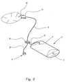
- FIG 3 is shown an embodiment of a collecting device 1 in accordance with the invention, in which two transverse walls 13, 13' are placed inside the collecting device 1 and transversally to its longitudinal direction between the inlet portion 7 and the outlet portion 11.
- the transverse wall 13 located nearest to the inlet portion 7 projects from the bottom portion of the collecting device 1 and approximately halfway up towards the top portion.
- the transverse wall 13' nearest to the outlet opening 11 covers the entire internal cross section of the collecting device 1.
- transverse walls 13, 13' may be placed inside the collecting device, even though two are shown in figure 3 . Further, it will be understood that the transverse walls 13, 13' may be placed at any desired angle to said longitudinal direction.
- the transverse walls 13, 13' have two purposes. Firstly, the transverse walls 13, 13' will function as bracing elements reinforcing the wall portions of the collecting device 1. Secondly, depending on their permeability, the transverse walls 13, 13' may function as a flow restriction, thereby defining chambers 15 in the collecting device 1. The chambers 15 may facilitate the inflation of the collecting device 1 and, at the same time, bring about a reduced flow rate of the fluid. A reduced flow rate will result in yet longer dwell time for the fluid in the collecting device 1 and thereby settling of fines nearer to the inlet opening 7 as compared with a collecting device 1 without transverse walls 13, 13'.
- transverse walls 13, 13' may cover all or only portions of a sectional area of the collecting device 1.
- FIG 3 is also shown a further conduit 17 which is connected to the supply conduit 2 upstream of the inlet opening 7.
- the purpose of the conduit 17 is to enable the addition of a binder or precipitating agent which helps to make the particulate substance occurring in a dispersed state in the liquid phase flocculate so that the particles will gather into larger and heavier particles and thereby bring about a faster and more efficient separation and sedimentation of the solids material.
- the binder is preferably an environmentally friendly chemical of a kind known per se-
- the binder is an organic binder.
- the collecting device 1 could be connected to systems (not shown) already existing, arranged to separate sand from well production, a so-called “subsea sand separator"
- the collecting device 1 is therefore provided with devices enabling movement of the collecting device 1 along the seabed or in the water masses.
- the devices may be lifting lugs for the connection of lifting devices such as a crane on a surface vessel and/or inflatable buoyancy elements.
Landscapes
- Engineering & Computer Science (AREA)
- Mining & Mineral Resources (AREA)
- Geology (AREA)
- Life Sciences & Earth Sciences (AREA)
- Fluid Mechanics (AREA)
- Geochemistry & Mineralogy (AREA)
- General Life Sciences & Earth Sciences (AREA)
- Physics & Mathematics (AREA)
- Environmental & Geological Engineering (AREA)
- Mechanical Engineering (AREA)
- Structural Engineering (AREA)
- General Engineering & Computer Science (AREA)
- Civil Engineering (AREA)
- Processing Of Solid Wastes (AREA)
- Treatment Of Sludge (AREA)
- Electrical Discharge Machining, Electrochemical Machining, And Combined Machining (AREA)
- Transition And Organic Metals Composition Catalysts For Addition Polymerization (AREA)
- Telephone Function (AREA)
- Electrotherapy Devices (AREA)
- Supplying Of Containers To The Packaging Station (AREA)
- Revetment (AREA)
- Drilling And Exploitation, And Mining Machines And Methods (AREA)
Claims (13)
- Sammelvorrichtung (1) für Festkörpermaterial, umfassend eine Zuführungsleitung (2), die durch das Mittel eines Fluids in der Zuführungsleitung (2) von einem ersten Ort auf einem Meeresboden, auf einer Offshore-Installation oder auf Land zu einem zweiten Ort transportiert wird, wobei das Fluid das Festkörpermaterial durch einen Einlassabschnitt (7) der Sammelvorrichtung (1) hinein transportiert, wobei die Sammelvorrichtung (1) mit einem oder mehreren permeablen Abschnitten versehen ist, die ausgestaltet sind, um Festkörpermaterial zurückzuhalten, welches eine vorbestimmte Grösse überschreitet, dadurch gekennzeichnet, dass die Zuführungsleitung (2) mit einer weiteren Leitung (17) versehen ist, um die Hinzufügung eines Bindemittels oder Fällungsmittels zu dem Fluid zu ermöglichen, welches in die Sammelvorrichtung (1) fliesst.
- Sammelvorrichtung in Übereinstimmung mit Anspruch 1, bei der die Sammelvorrichtung (1) durch einen Behälter gebildet ist.
- Sammelvorrichtung in Übereinstimmung mit Anspruch 1, bei der der mindestens eine permeable Abschnitt einen ansteigenden Grad an Permeabilität in Richtung von dem Einlassabschnitt (7) in Richtung von einem oder mehreren Abschnitten in einem Abstand von dem Einlassabschnitt (7) der Sammelvorrichtung (1) aufweist,.
- Sammelvorrichtung in Übereinstimmung mit Anspruch 3, bei der der ansteigende Grad der Permeabilität durch das Mittel von grösseren Öffnungen in dem Wandabschnitt der Sammelvorrichtung (1) bereitgestellt ist.
- Sammelvorrichtung in Übereinstimmung mit Anspruch 1, bei der der mindestens eine permeable Abschnitt mit Öffnungen einer ersten Grösse versehen ist, und bei der in einem Abstand von dem Einlassabschnitt (7) mindestens eine Auslassöffnung (11) angeordnet ist, welche eine Öffnung einer zweiten Grösse aufweist, wobei die erste Grösse kleiner als die zweite Grösse ist.
- Sammelvorrichtung in Übereinstimmung mit Anspruch 5, bei der die Auslassöffnung (1) durch einen offenen Abschnitt ausgebildet ist, welcher angeordnet ist, um Fluid im Wesentlichen in derselben Rate herauszulassen, wie die, zu welcher das Fluid in die Sammelvorrichtung (1) eingebracht wird.
- Sammelvorrichtung in Übereinstimmung mit irgendeinem der vorstehenden Ansprüche, bei der die Sammelvorrichtung (1) mit mindestens einer inneren den Fluss begrenzenden Vorrichtung (13, 13') versehen ist.
- Vorrichtung in Übereinstimmung mit irgendeinem der vorstehenden Ansprüche, bei der die Sammelvorrichtung (1) mit dem Mittel von mindestens zwei Materialen mit unterschiedlichen mechanischen Eigenschaften versehen ist.
- Sammelvorrichtung in Übereinstimmung mit Anspruch 8, bei der die Sammelvorrichtung (1) eine grössere mechanische Stärke an einem Einlassabschnitt aufweist als an einer oder mehreren Abschnitten, die in einem Abstand von dem Einlassabschnitt vorgesehen sind.
- Sammelvorrichtung in Übereinstimmung mit irgendeinem der vorstehenden Ansprüche, bei der mindestens Abschnitte der Sammelvorrichtung (1) aus einem biologisch abbaubaren Material hergestellt sind.
- Sammelvorrichtung in Übereinstimmung mit Anspruch 1, bei der das Fluid in die Sammelvorrichtung (1) durch das Mittel einer Pumpe (5) eingebracht wird.
- Verfahren zum Sammeln eines Festkörpermaterials, welcher von einem ersten Ort auf einem Meeresgrund oder auf Land zu einem zweiten Ort bewegt wird, wobei das Verfahren die Schritte umfasst:- Anordnen einer Sammelvorrichtung (1), welche mit einer oder mehreren permeablen Abschnitten versehen ist, die angeordnet sind, um Festkörpermaterial über eine vorbestimmte Grösse hinaus zurückzuhalten, an diesem zweiten Ort;- Bewegen des Festkörpermaterials durch das Mittel eines Fluids, welches durch einen Einlassabschnitt (7) der Sammelvorrichtung (1) eingebracht wird; und- Aufgeben der gefüllten Sammelvorrichtung nachdem das Einbringen des Festkörpermaterials abgeschlossen oder nachdem die Sammelvorrichtung (1) mit einer vorbestimmten Menge von Festkörpermaterial gefüllt ist,dadurch gekennzeichnet, dass das Verfahren weiterhin das Einzufügen eines Bindemittels oder eines Fällungsmittels zu dem Fluid umfasst, welches in die Sammelvorrichtung (1) fliesst.
- Verfahren in Übereinstimmung mit Anspruch 12, bei dem das Fluid in die Sammelvorrichtung (1) durch das Mittel einer Pumpe (5) eingebracht wird.
Applications Claiming Priority (2)
| Application Number | Priority Date | Filing Date | Title |
|---|---|---|---|
| NO20076546A NO327759B1 (no) | 2007-12-19 | 2007-12-19 | Oppsamlingsanordning og framgangsmate ved bruk av samme |
| PCT/NO2008/000447 WO2009078731A2 (en) | 2007-12-19 | 2008-12-15 | A collecting device and a method of using same |
Publications (2)
| Publication Number | Publication Date |
|---|---|
| EP2232004A2 EP2232004A2 (de) | 2010-09-29 |
| EP2232004B1 true EP2232004B1 (de) | 2011-06-08 |
Family
ID=40651325
Family Applications (1)
| Application Number | Title | Priority Date | Filing Date |
|---|---|---|---|
| EP08861254A Not-in-force EP2232004B1 (de) | 2007-12-19 | 2008-12-15 | SammelVORRICHTUNG UND VERFAHREN ZU IHRER ANWENDUNG |
Country Status (9)
| Country | Link |
|---|---|
| US (1) | US8550568B2 (de) |
| EP (1) | EP2232004B1 (de) |
| AT (1) | ATE512279T1 (de) |
| BR (1) | BRPI0821030A2 (de) |
| CA (1) | CA2709124C (de) |
| DK (1) | DK2232004T3 (de) |
| ES (1) | ES2369839T3 (de) |
| NO (1) | NO327759B1 (de) |
| WO (1) | WO2009078731A2 (de) |
Families Citing this family (8)
| Publication number | Priority date | Publication date | Assignee | Title |
|---|---|---|---|---|
| NO329529B1 (no) | 2008-03-28 | 2010-11-08 | Ott Subsea Bag Technology As | Oppsamlingsanordning og framgangsmate ved bruk av samme |
| NO334829B1 (no) | 2009-06-18 | 2014-06-10 | Ott Subsea Bag Technology As | Framgangsmåte for deponering av boreavfall, forurensete sedimenter og restavfall og et deponi for samme |
| JP2014522923A (ja) * | 2011-06-17 | 2014-09-08 | ノーチラス・ミネラルズ・パシフイツク・プロプライエタリー・リミテツド | 海底貯鉱のための装置および方法 |
| KR101930377B1 (ko) * | 2011-06-17 | 2018-12-18 | 노틸러스 미네랄즈 퍼시픽 피티 리미티드 | 해저 비축 시스템 및 방법 |
| US9679157B2 (en) | 2015-01-07 | 2017-06-13 | International Business Machines Corporation | Limiting exposure to compliance and risk in a cloud environment |
| NO340143B1 (en) * | 2015-06-17 | 2017-03-13 | Kongsberg Oil & Gas Tech As | Method and system for subsea separation of produced water |
| EP4471217A3 (de) * | 2020-05-25 | 2025-03-19 | Wing Marine LLC | Materialhandhabungssysteme und -verfahren |
| US12320087B2 (en) * | 2021-07-14 | 2025-06-03 | The United States Of America As Represented By The Secretary Of Agriculture | Submerged liquid intake strainers |
Family Cites Families (13)
| Publication number | Priority date | Publication date | Assignee | Title |
|---|---|---|---|---|
| US3817383A (en) * | 1972-07-26 | 1974-06-18 | B Michel | Apparatus for removing particulate matter |
| FR2238035B1 (de) * | 1973-07-18 | 1981-04-17 | Commissariat Energie Atomique | |
| US4133761A (en) * | 1977-04-25 | 1979-01-09 | Posgate Edward S | Submerged settler for suspended solids |
| US5004051A (en) * | 1989-09-12 | 1991-04-02 | Norwegian Contracts A/S | Method and means for cleansing and storing drill cuttings from drilling operations in the sea bottom |
| US5232475A (en) * | 1992-08-24 | 1993-08-03 | Ohio University | Slug flow eliminator and separator |
| US6062313A (en) * | 1998-03-09 | 2000-05-16 | Moore; Boyd B. | Expandable tank for separating particulate material from drilling fluid and storing production fluids, and method |
| GB9920819D0 (en) * | 1999-09-04 | 1999-11-10 | Martin Andrew | Drilling waste handling |
| BR0308522B1 (pt) * | 2002-03-18 | 2013-04-16 | sistema e mÉtodo para a recuperaÇço de um fluido de retorno de furos de poÇos submarinos. | |
| NO320113B1 (no) | 2003-12-03 | 2005-10-24 | Incoronato Arne | Anordning og fremgangsmate ved oppsamling av vannholdig borekaks fra en bronn |
| US7261164B2 (en) * | 2004-01-23 | 2007-08-28 | Baker Hughes Incorporated | Floatable drill cuttings bag and method and system for use in cuttings disposal |
| US8757389B2 (en) * | 2004-12-23 | 2014-06-24 | Georgia-Pacific Chemicals Llc | Amine-aldehyde resins and uses thereof in separation processes |
| US7086472B1 (en) * | 2005-04-08 | 2006-08-08 | Arne Incoronato | Device and method of collecting solids from a well |
| EP2070874A1 (de) * | 2007-12-13 | 2009-06-17 | Creaholic SA | Wasseraufbereitungsvorrichtung |
-
2007
- 2007-12-19 NO NO20076546A patent/NO327759B1/no not_active IP Right Cessation
-
2008
- 2008-12-15 CA CA2709124A patent/CA2709124C/en not_active Expired - Fee Related
- 2008-12-15 ES ES08861254T patent/ES2369839T3/es active Active
- 2008-12-15 AT AT08861254T patent/ATE512279T1/de not_active IP Right Cessation
- 2008-12-15 BR BRPI0821030-6A patent/BRPI0821030A2/pt active Search and Examination
- 2008-12-15 US US12/808,514 patent/US8550568B2/en not_active Expired - Fee Related
- 2008-12-15 WO PCT/NO2008/000447 patent/WO2009078731A2/en not_active Ceased
- 2008-12-15 DK DK08861254.4T patent/DK2232004T3/da active
- 2008-12-15 EP EP08861254A patent/EP2232004B1/de not_active Not-in-force
Also Published As
| Publication number | Publication date |
|---|---|
| US8550568B2 (en) | 2013-10-08 |
| WO2009078731A3 (en) | 2009-09-17 |
| ES2369839T3 (es) | 2011-12-07 |
| NO327759B1 (no) | 2009-09-21 |
| US20100303558A1 (en) | 2010-12-02 |
| EP2232004A2 (de) | 2010-09-29 |
| ATE512279T1 (de) | 2011-06-15 |
| BRPI0821030A2 (pt) | 2015-06-16 |
| CA2709124C (en) | 2016-05-17 |
| DK2232004T3 (da) | 2011-09-26 |
| CA2709124A1 (en) | 2009-06-25 |
| NO20076546L (no) | 2009-06-22 |
| WO2009078731A2 (en) | 2009-06-25 |
Similar Documents
| Publication | Publication Date | Title |
|---|---|---|
| EP2232004B1 (de) | SammelVORRICHTUNG UND VERFAHREN ZU IHRER ANWENDUNG | |
| JP6106165B2 (ja) | 海底ストックパイルシステム及び方法 | |
| CN103717835B (zh) | 用于海底堆存的设备及方法 | |
| AU2012247461B2 (en) | Device for extracting solid material on the bed of a body of water, and associated method | |
| US8888671B2 (en) | Method for disposal of drilling waste, contaminated sediments and residual waste and a disposal facility for same | |
| EP0438683B1 (de) | Verfahren und Vorrichtung zum Aufbringen von Feinstmaterial auf den Grund und die Böschungen des Nasstagebaus | |
| EP2268889B1 (de) | Sammelvorrichtung und diese verwendendes verfahren | |
| WO2002057551A1 (en) | Method for hydraulic subsea dredging | |
| CN212405291U (zh) | 一种多功能挖掘机清淤船 | |
| KR101550363B1 (ko) | 준설장치 | |
| ES2221771B1 (es) | Procedimiento y equipo de dragado. | |
| Land | Dredging and disposal of contaminated | |
| Land | Dredging and disposal of contaminated sediments | |
| CZ9902946A3 (cs) | Způsob těžby vodárenských sedimentů a zařízení pro provádění tohoto způsobu | |
| HK1086049B (en) | Method for removal of sand | |
| HK1086049A1 (en) | Method for removal of sand |
Legal Events
| Date | Code | Title | Description |
|---|---|---|---|
| PUAI | Public reference made under article 153(3) epc to a published international application that has entered the european phase |
Free format text: ORIGINAL CODE: 0009012 |
|
| 17P | Request for examination filed |
Effective date: 20100609 |
|
| AK | Designated contracting states |
Kind code of ref document: A2 Designated state(s): AT BE BG CH CY CZ DE DK EE ES FI FR GB GR HR HU IE IS IT LI LT LU LV MC MT NL NO PL PT RO SE SI SK TR |
|
| AX | Request for extension of the european patent |
Extension state: AL BA MK RS |
|
| GRAP | Despatch of communication of intention to grant a patent |
Free format text: ORIGINAL CODE: EPIDOSNIGR1 |
|
| DAX | Request for extension of the european patent (deleted) | ||
| GRAS | Grant fee paid |
Free format text: ORIGINAL CODE: EPIDOSNIGR3 |
|
| GRAA | (expected) grant |
Free format text: ORIGINAL CODE: 0009210 |
|
| AK | Designated contracting states |
Kind code of ref document: B1 Designated state(s): AT BE BG CH CY CZ DE DK EE ES FI FR GB GR HR HU IE IS IT LI LT LU LV MC MT NL NO PL PT RO SE SI SK TR |
|
| REG | Reference to a national code |
Ref country code: GB Ref legal event code: FG4D |
|
| REG | Reference to a national code |
Ref country code: CH Ref legal event code: EP |
|
| REG | Reference to a national code |
Ref country code: IE Ref legal event code: FG4D |
|
| REG | Reference to a national code |
Ref country code: DE Ref legal event code: R096 Ref document number: 602008007517 Country of ref document: DE Effective date: 20110721 |
|
| REG | Reference to a national code |
Ref country code: NL Ref legal event code: T3 |
|
| REG | Reference to a national code |
Ref country code: DK Ref legal event code: T3 |
|
| PG25 | Lapsed in a contracting state [announced via postgrant information from national office to epo] |
Ref country code: NO Free format text: LAPSE BECAUSE OF FAILURE TO SUBMIT A TRANSLATION OF THE DESCRIPTION OR TO PAY THE FEE WITHIN THE PRESCRIBED TIME-LIMIT Effective date: 20110908 Ref country code: SE Free format text: LAPSE BECAUSE OF FAILURE TO SUBMIT A TRANSLATION OF THE DESCRIPTION OR TO PAY THE FEE WITHIN THE PRESCRIBED TIME-LIMIT Effective date: 20110608 Ref country code: HR Free format text: LAPSE BECAUSE OF FAILURE TO SUBMIT A TRANSLATION OF THE DESCRIPTION OR TO PAY THE FEE WITHIN THE PRESCRIBED TIME-LIMIT Effective date: 20110608 Ref country code: LT Free format text: LAPSE BECAUSE OF FAILURE TO SUBMIT A TRANSLATION OF THE DESCRIPTION OR TO PAY THE FEE WITHIN THE PRESCRIBED TIME-LIMIT Effective date: 20110608 |
|
| PG25 | Lapsed in a contracting state [announced via postgrant information from national office to epo] |
Ref country code: SI Free format text: LAPSE BECAUSE OF FAILURE TO SUBMIT A TRANSLATION OF THE DESCRIPTION OR TO PAY THE FEE WITHIN THE PRESCRIBED TIME-LIMIT Effective date: 20110608 Ref country code: LV Free format text: LAPSE BECAUSE OF FAILURE TO SUBMIT A TRANSLATION OF THE DESCRIPTION OR TO PAY THE FEE WITHIN THE PRESCRIBED TIME-LIMIT Effective date: 20110608 Ref country code: CY Free format text: LAPSE BECAUSE OF FAILURE TO SUBMIT A TRANSLATION OF THE DESCRIPTION OR TO PAY THE FEE WITHIN THE PRESCRIBED TIME-LIMIT Effective date: 20110608 Ref country code: GR Free format text: LAPSE BECAUSE OF FAILURE TO SUBMIT A TRANSLATION OF THE DESCRIPTION OR TO PAY THE FEE WITHIN THE PRESCRIBED TIME-LIMIT Effective date: 20110909 Ref country code: FI Free format text: LAPSE BECAUSE OF FAILURE TO SUBMIT A TRANSLATION OF THE DESCRIPTION OR TO PAY THE FEE WITHIN THE PRESCRIBED TIME-LIMIT Effective date: 20110608 Ref country code: AT Free format text: LAPSE BECAUSE OF FAILURE TO SUBMIT A TRANSLATION OF THE DESCRIPTION OR TO PAY THE FEE WITHIN THE PRESCRIBED TIME-LIMIT Effective date: 20110608 |
|
| REG | Reference to a national code |
Ref country code: CH Ref legal event code: NV Representative=s name: ISLER & PEDRAZZINI AG |
|
| REG | Reference to a national code |
Ref country code: ES Ref legal event code: FG2A Ref document number: 2369839 Country of ref document: ES Kind code of ref document: T3 Effective date: 20111207 |
|
| PG25 | Lapsed in a contracting state [announced via postgrant information from national office to epo] |
Ref country code: BE Free format text: LAPSE BECAUSE OF FAILURE TO SUBMIT A TRANSLATION OF THE DESCRIPTION OR TO PAY THE FEE WITHIN THE PRESCRIBED TIME-LIMIT Effective date: 20110608 |
|
| PG25 | Lapsed in a contracting state [announced via postgrant information from national office to epo] |
Ref country code: PT Free format text: LAPSE BECAUSE OF FAILURE TO SUBMIT A TRANSLATION OF THE DESCRIPTION OR TO PAY THE FEE WITHIN THE PRESCRIBED TIME-LIMIT Effective date: 20111010 Ref country code: CZ Free format text: LAPSE BECAUSE OF FAILURE TO SUBMIT A TRANSLATION OF THE DESCRIPTION OR TO PAY THE FEE WITHIN THE PRESCRIBED TIME-LIMIT Effective date: 20110608 Ref country code: EE Free format text: LAPSE BECAUSE OF FAILURE TO SUBMIT A TRANSLATION OF THE DESCRIPTION OR TO PAY THE FEE WITHIN THE PRESCRIBED TIME-LIMIT Effective date: 20110608 |
|
| PG25 | Lapsed in a contracting state [announced via postgrant information from national office to epo] |
Ref country code: SK Free format text: LAPSE BECAUSE OF FAILURE TO SUBMIT A TRANSLATION OF THE DESCRIPTION OR TO PAY THE FEE WITHIN THE PRESCRIBED TIME-LIMIT Effective date: 20110608 Ref country code: PL Free format text: LAPSE BECAUSE OF FAILURE TO SUBMIT A TRANSLATION OF THE DESCRIPTION OR TO PAY THE FEE WITHIN THE PRESCRIBED TIME-LIMIT Effective date: 20110608 Ref country code: RO Free format text: LAPSE BECAUSE OF FAILURE TO SUBMIT A TRANSLATION OF THE DESCRIPTION OR TO PAY THE FEE WITHIN THE PRESCRIBED TIME-LIMIT Effective date: 20110608 |
|
| PLBE | No opposition filed within time limit |
Free format text: ORIGINAL CODE: 0009261 |
|
| STAA | Information on the status of an ep patent application or granted ep patent |
Free format text: STATUS: NO OPPOSITION FILED WITHIN TIME LIMIT |
|
| 26N | No opposition filed |
Effective date: 20120309 |
|
| PG25 | Lapsed in a contracting state [announced via postgrant information from national office to epo] |
Ref country code: IT Free format text: LAPSE BECAUSE OF FAILURE TO SUBMIT A TRANSLATION OF THE DESCRIPTION OR TO PAY THE FEE WITHIN THE PRESCRIBED TIME-LIMIT Effective date: 20110608 |
|
| REG | Reference to a national code |
Ref country code: DE Ref legal event code: R097 Ref document number: 602008007517 Country of ref document: DE Effective date: 20120309 |
|
| PG25 | Lapsed in a contracting state [announced via postgrant information from national office to epo] |
Ref country code: MT Free format text: LAPSE BECAUSE OF FAILURE TO SUBMIT A TRANSLATION OF THE DESCRIPTION OR TO PAY THE FEE WITHIN THE PRESCRIBED TIME-LIMIT Effective date: 20110608 |
|
| PG25 | Lapsed in a contracting state [announced via postgrant information from national office to epo] |
Ref country code: BG Free format text: LAPSE BECAUSE OF FAILURE TO SUBMIT A TRANSLATION OF THE DESCRIPTION OR TO PAY THE FEE WITHIN THE PRESCRIBED TIME-LIMIT Effective date: 20110908 |
|
| PG25 | Lapsed in a contracting state [announced via postgrant information from national office to epo] |
Ref country code: TR Free format text: LAPSE BECAUSE OF FAILURE TO SUBMIT A TRANSLATION OF THE DESCRIPTION OR TO PAY THE FEE WITHIN THE PRESCRIBED TIME-LIMIT Effective date: 20110608 |
|
| PG25 | Lapsed in a contracting state [announced via postgrant information from national office to epo] |
Ref country code: HU Free format text: LAPSE BECAUSE OF FAILURE TO SUBMIT A TRANSLATION OF THE DESCRIPTION OR TO PAY THE FEE WITHIN THE PRESCRIBED TIME-LIMIT Effective date: 20110608 |
|
| PGFP | Annual fee paid to national office [announced via postgrant information from national office to epo] |
Ref country code: DK Payment date: 20141215 Year of fee payment: 7 |
|
| PGFP | Annual fee paid to national office [announced via postgrant information from national office to epo] |
Ref country code: MC Payment date: 20141125 Year of fee payment: 7 Ref country code: GB Payment date: 20141124 Year of fee payment: 7 Ref country code: IE Payment date: 20141202 Year of fee payment: 7 Ref country code: ES Payment date: 20141118 Year of fee payment: 7 |
|
| PGFP | Annual fee paid to national office [announced via postgrant information from national office to epo] |
Ref country code: IS Payment date: 20141222 Year of fee payment: 7 Ref country code: NL Payment date: 20141219 Year of fee payment: 7 |
|
| PGFP | Annual fee paid to national office [announced via postgrant information from national office to epo] |
Ref country code: DE Payment date: 20150211 Year of fee payment: 7 |
|
| PGFP | Annual fee paid to national office [announced via postgrant information from national office to epo] |
Ref country code: FR Payment date: 20141211 Year of fee payment: 7 |
|
| PGFP | Annual fee paid to national office [announced via postgrant information from national office to epo] |
Ref country code: CH Payment date: 20151211 Year of fee payment: 8 |
|
| PGFP | Annual fee paid to national office [announced via postgrant information from national office to epo] |
Ref country code: LU Payment date: 20151224 Year of fee payment: 8 |
|
| REG | Reference to a national code |
Ref country code: DE Ref legal event code: R119 Ref document number: 602008007517 Country of ref document: DE |
|
| REG | Reference to a national code |
Ref country code: DK Ref legal event code: EBP Effective date: 20151231 |
|
| PG25 | Lapsed in a contracting state [announced via postgrant information from national office to epo] |
Ref country code: MC Free format text: LAPSE BECAUSE OF NON-PAYMENT OF DUE FEES Effective date: 20151231 |
|
| GBPC | Gb: european patent ceased through non-payment of renewal fee |
Effective date: 20151215 |
|
| REG | Reference to a national code |
Ref country code: NL Ref legal event code: MM Effective date: 20160101 |
|
| REG | Reference to a national code |
Ref country code: IE Ref legal event code: MM4A |
|
| REG | Reference to a national code |
Ref country code: FR Ref legal event code: ST Effective date: 20160831 |
|
| PG25 | Lapsed in a contracting state [announced via postgrant information from national office to epo] |
Ref country code: GB Free format text: LAPSE BECAUSE OF NON-PAYMENT OF DUE FEES Effective date: 20151215 Ref country code: NL Free format text: LAPSE BECAUSE OF NON-PAYMENT OF DUE FEES Effective date: 20160101 Ref country code: DE Free format text: LAPSE BECAUSE OF NON-PAYMENT OF DUE FEES Effective date: 20160701 Ref country code: IE Free format text: LAPSE BECAUSE OF NON-PAYMENT OF DUE FEES Effective date: 20151215 |
|
| PG25 | Lapsed in a contracting state [announced via postgrant information from national office to epo] |
Ref country code: FR Free format text: LAPSE BECAUSE OF NON-PAYMENT OF DUE FEES Effective date: 20151231 |
|
| REG | Reference to a national code |
Ref country code: ES Ref legal event code: FD2A Effective date: 20170127 |
|
| PG25 | Lapsed in a contracting state [announced via postgrant information from national office to epo] |
Ref country code: DK Free format text: LAPSE BECAUSE OF NON-PAYMENT OF DUE FEES Effective date: 20151231 |
|
| PG25 | Lapsed in a contracting state [announced via postgrant information from national office to epo] |
Ref country code: ES Free format text: LAPSE BECAUSE OF NON-PAYMENT OF DUE FEES Effective date: 20151216 |
|
| PG25 | Lapsed in a contracting state [announced via postgrant information from national office to epo] |
Ref country code: IS Free format text: LAPSE BECAUSE OF NON-PAYMENT OF DUE FEES Effective date: 20160630 |
|
| REG | Reference to a national code |
Ref country code: CH Ref legal event code: PL |
|
| PG25 | Lapsed in a contracting state [announced via postgrant information from national office to epo] |
Ref country code: LI Free format text: LAPSE BECAUSE OF NON-PAYMENT OF DUE FEES Effective date: 20161231 Ref country code: CH Free format text: LAPSE BECAUSE OF NON-PAYMENT OF DUE FEES Effective date: 20161231 Ref country code: LU Free format text: LAPSE BECAUSE OF NON-PAYMENT OF DUE FEES Effective date: 20161215 |