EP2231985B1 - Fresh air valve - Google Patents
Fresh air valve Download PDFInfo
- Publication number
- EP2231985B1 EP2231985B1 EP08856611.2A EP08856611A EP2231985B1 EP 2231985 B1 EP2231985 B1 EP 2231985B1 EP 08856611 A EP08856611 A EP 08856611A EP 2231985 B1 EP2231985 B1 EP 2231985B1
- Authority
- EP
- European Patent Office
- Prior art keywords
- fresh
- air valve
- track
- ventilation flap
- flow opening
- Prior art date
- Legal status (The legal status is an assumption and is not a legal conclusion. Google has not performed a legal analysis and makes no representation as to the accuracy of the status listed.)
- Active
Links
- 238000009423 ventilation Methods 0.000 claims description 58
- 230000008878 coupling Effects 0.000 claims description 46
- 238000010168 coupling process Methods 0.000 claims description 46
- 238000005859 coupling reaction Methods 0.000 claims description 46
- 238000007789 sealing Methods 0.000 claims description 16
- 230000000694 effects Effects 0.000 claims description 8
- 230000006835 compression Effects 0.000 claims description 7
- 238000007906 compression Methods 0.000 claims description 7
- 230000003247 decreasing effect Effects 0.000 claims description 5
- 238000006073 displacement reaction Methods 0.000 claims description 3
- 238000001746 injection moulding Methods 0.000 claims description 2
- 210000002105 tongue Anatomy 0.000 description 10
- 229910052751 metal Inorganic materials 0.000 description 6
- 239000002184 metal Substances 0.000 description 6
- 238000010276 construction Methods 0.000 description 5
- 239000000463 material Substances 0.000 description 5
- XLYOFNOQVPJJNP-UHFFFAOYSA-N water Substances O XLYOFNOQVPJJNP-UHFFFAOYSA-N 0.000 description 5
- 239000004411 aluminium Substances 0.000 description 3
- 229910052782 aluminium Inorganic materials 0.000 description 3
- XAGFODPZIPBFFR-UHFFFAOYSA-N aluminium Chemical compound [Al] XAGFODPZIPBFFR-UHFFFAOYSA-N 0.000 description 3
- 238000003825 pressing Methods 0.000 description 3
- 239000000243 solution Substances 0.000 description 3
- 230000015572 biosynthetic process Effects 0.000 description 2
- 238000003780 insertion Methods 0.000 description 2
- 230000037431 insertion Effects 0.000 description 2
- 239000011810 insulating material Substances 0.000 description 2
- 238000009413 insulation Methods 0.000 description 2
- 239000004033 plastic Substances 0.000 description 2
- 230000003019 stabilising effect Effects 0.000 description 2
- 238000005728 strengthening Methods 0.000 description 2
- 230000004308 accommodation Effects 0.000 description 1
- 239000004020 conductor Substances 0.000 description 1
- 238000001816 cooling Methods 0.000 description 1
- 239000000428 dust Substances 0.000 description 1
- 238000002347 injection Methods 0.000 description 1
- 239000007924 injection Substances 0.000 description 1
- 238000012423 maintenance Methods 0.000 description 1
- 230000014759 maintenance of location Effects 0.000 description 1
- 238000004519 manufacturing process Methods 0.000 description 1
- 239000002991 molded plastic Substances 0.000 description 1
- 238000000465 moulding Methods 0.000 description 1
- 239000012858 resilient material Substances 0.000 description 1
- 230000000717 retained effect Effects 0.000 description 1
- 239000007787 solid Substances 0.000 description 1
- 230000003068 static effect Effects 0.000 description 1
Images


Classifications
-
- F—MECHANICAL ENGINEERING; LIGHTING; HEATING; WEAPONS; BLASTING
- F24—HEATING; RANGES; VENTILATING
- F24F—AIR-CONDITIONING; AIR-HUMIDIFICATION; VENTILATION; USE OF AIR CURRENTS FOR SCREENING
- F24F13/00—Details common to, or for air-conditioning, air-humidification, ventilation or use of air currents for screening
- F24F13/08—Air-flow control members, e.g. louvres, grilles, flaps or guide plates
- F24F13/18—Air-flow control members, e.g. louvres, grilles, flaps or guide plates specially adapted for insertion in flat panels, e.g. in door or window-pane
-
- E—FIXED CONSTRUCTIONS
- E04—BUILDING
- E04D—ROOF COVERINGS; SKY-LIGHTS; GUTTERS; ROOF-WORKING TOOLS
- E04D13/00—Special arrangements or devices in connection with roof coverings; Protection against birds; Roof drainage ; Sky-lights
- E04D13/03—Sky-lights; Domes; Ventilating sky-lights
- E04D13/0325—Sky-lights; Domes; Ventilating sky-lights provided with ventilating means
Definitions
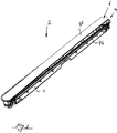
- the present invention relates to a fresh-air valve of the kind which comprises a housing for building into a slot-shaped opening in walls or frames, for example a window frame, and comprising an elongated ventilation flap with ends which are connected with pressure-releasable snap couplings disposed at the ends of the housing, and which can be activated between an open and a closed position for the ventilation flap.
- the valve can appear completely without operating elements, and since the ventilation flap/plate is in longitudinal tipping connection with the snap couplings, it is without significance whether it is tipped obliquely during the movement inwards or outwards.
- the ventilation flap/plate consists of a hollow metal profile, typically of aluminium, in the open ends of which protruding tongues on the pressure-operated snap couplings can be engaged by being pressed in, which has led to the metal look on the surface of the valve, which is desired by the purchasers.
- the construction of the fresh-air valve disclosed in WO 2006/131125 A1 further makes possible a relatively small building-in depth, which is preferred by many manufacturers of doors and windows into which the fresh-air valve is built.
- Another solution of the problem could be to manufacture the flap/plate in a non metallic, insulating material, but this would eliminate the desired genuine metal look preferred by the purchasers.
- a fresh-air valve of the kind which comprises an elongated channel bush with a substantially slot-shaped through-flow opening for building into a slot.-shaped opening in walls or frames, for example a window frame, and further comprising an elongated ventilation flap with ends which are connected with pressure-releasable snap couplings disposed in wells near each end of the housing, outside the through-flow opening, where said pressure-releasable snap couplings can be activated between an open and a closed position for the ventilation flap, where the upper side of this is on a level with the facing side of the channel bush, and where between the channel bush and the ventilation flap there is a sealing strip disposed in an annular recess along the edge of the through-flow opening of the channel bush, which is characterised in that oriented towards the through-flow opening the ventilation flap comprises an insulating casing, the side limits of which comprise parallel-extending, upstanding lobes on the side facing away from the channel bush, and oriented in the longitudinal axis of the cas
- the flap/plate of the fresh air valve consists of an assembled two-part body comprising an insulating casing closest to the flow through opening of the channel bush of the fresh air valve which is affected by colder air from the outride, and the preferred metal plate on the inside of the fresh air valve. Further, that between the insulating casing and the cover plate there is formed a space with static air, due to the protruding lobes on the side facing the cover plate, which creates a distance between the insulating casing and the cover plate.
- the construction makes it possible to use any kind of material for the configuration of the cover plate, whether be it metal/aluminium, plastic or other material which for aesthetic reasons is desired to be used out of regard for the overall impression of the door or window frame in which the fresh-air valve according to the invention is incorporated.
- a further advantage of this construction of the fresh-air valve is that its insulating properties are improved in comparison with the known valves with a solid cover plate or ventilation flap e.g. as the one disclosed in WO 2006/131125 A1 .
- the insulating casing is configured in at least a poor heat-conducting material. However, it is preferred that the insulating casing is made of a plastic material.
- the problem of forming of condensate water known from the fresh air valve disclosed in WO 2006/131125 A1 is by the fresh air valve according to the invention with an assembled two-part flap/cover of which the one is made of insulating material, solved in an manner which should not considered to be obvious for a skilled person, as the solution meets more requirements than just adding an insulating layer on the side og the flap/cover plate adjacent to the flow through opening of the fresh air valve, which would reduce the size of the free opening of the fresh air valve. Further the fresh air valve according to the invention also allows for the election of a lot of different materials for the inside part of the flap/cover.
- the insulating casing can at the ends comprise a protruding part oriented in the direction of the through-flow opening, said protruding parts forming a part of the pressure-releasable snap couplings.
- the number of individual parts of which the fresh-air valve consists is hereby reduced by a single part in relation to the fresh-air valve disclosed in WO 2006 131125 .
- the fresh-air valve's ventilation flap is supported substantially by the pressure-operated snap couplings, which are vulnerable to transversely-directed pressure forces, which means that these can be ruined by excessive operation with an obliquely transverse pressure force, with subsequent costs of repair.
- this can comprise an end stop for the ventilation flap in its open position.
- the ventilation flap is hereby stabilised so that it can better withstand transversely-directed pressure forces, which is achieved by the end stops to some degree absorbing the effect of said pressure forces, together with the load on the snap couplings being correspondingly reduced.
- the wedge-shaped side surfaces opposite the plane sides of the barbs enable an easy and trouble-free assembly of the fresh-air valve, where with the insertion of the insulating casing in the channel bush, the barbs yield slightly towards each other during the contact of the wedge-shaped surfaces against the standing-out parts in the channel bush, and thereafter during continued insertion of the insulating casing are displaced to the start position, whereby the plane surfaces are locked behind the channel bush's standing-out parts.
- the pressure-operated snap couplings are arranged so that the protruding parts are cooperating with and displaceable in the coupling wells, in that the extending parts comprise protruding guide lugs which cooperate with guide tracks in at least in two opposing and facing towards the end parts sides of respectively the first and the second coupling well, and that extending parts further comprise a space for receiving a compression spring in which there is housed the first leg of a substantially U-shaped snap element, so that the compression spring rests against the bottom of the U-profile, and said U-shaped snap element in extension of the bottom of the U-profile further comprises a protruding retaining lug for engagement in a cooperating recess/hole in the sides of the coupling wells, and where the U-shaped snap element's second leg comprises a protruding retaining lug element which is oriented towards and accommodated in a track system in the extending parts
- the extending parts can comprise end-protection caps which extent between the cover plate and are oriented towards the coupling wells, at least to a level with the retaining lug element, said end-protection caps covering at least the upstanding parts which comprise the track system which at any time extend out over the edge or the channel bush.
- the track system of the pressure-operated snap couplings is hereby safeguarded against soiling, which results in long operational reliability and in practice eliminates all maintenance of the pressure-operated snap couplings.
- the lip ring can with advantage be moulded together with the channel bush by two-component injection moulding.
- the necessary open height is reduced with the height of the sealing strip, in that the sealing strip is disposed in the recess in the channel bush.
- the two-component moulding there is also achieved the advantage that one hereby saves the operation which is connected with the adhering/mounting of the sealing strip.
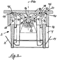
- the insulating casing can have a double concave cross-section between the longitudinal axis and the side edges of the casing.
- the sides of the coupling wells facing towards the through-flow opening can have an extent which corresponds to the facing side of the insulating casing, and over which extent the sealing strip extends.
- the channel bush in the fresh-air valve is typically made of injection moulded plastic, and is a relatively thin-walled construction which, during the pressing into a window frame or windowsill, can break. With the object of providing the channel bush with adequate stability, a number of transverse bridges can be provided in the through-flow opening.
- the end parts of the bridges facing towards the ventilation flap can be formed with an extent which corresponds to the facing side of the insulating casing.
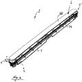
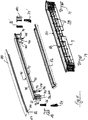
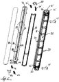
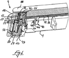
- the fresh-air valve 2 consists of a channel bush 4, a ventilation flap 6 which comprises an insulating casing 76, and a cover plate 88.
- the insulating casing 76 comprises a track 82 with protruding lugs 84 intended for engagement, pressing-in and locking of protruding side edges 83, 85 on protruding locking tongues 86 along the centre axis 87 of the cover plate 88, see also fig. 8 and fig. 9 .
- the cover plate 88 can consist of a suitably stiff material, for example aluminium.
- the insulation casing 76 also comprises upstanding lobes 95 along with the parallel side edges 94 on the side facing the cover plate 88.
- the depth of the track 82 is slightly deeper than the extent of the locking tongue 86 on the cover plate 88, which means that there is air between the locking tongue 86 and the insulation casing 76, which is thus only in contact with the locking tongue's protruding side edges 83, 85 at contact points at the spaced lugs 84.
- the effect of the presence of the protruding lobes 95 on the parallel side edges 94 of the insulating casing is that the side of the cover plate 88 facing towards the insulating casing 76 is only in contact with the protruding lobes 95, and further that there is space between the cover plate 88 and the remaining part of the insulating casing 76.
- the insulating casing 76 comprises extending parts 42, 42' which constitute a part of the pressure-releasable snap couplings 9, 9', which connect the ventilation flap 6 and the channel bush, with the extending parts 42, 42' being disposed in coupling wells 10, 10' at the ends of the channel, bush 4.
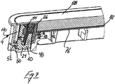
- the fresh-air valve 2 comprises two end stops 97 for the ventilation flap in its open position, as will appear most clearly in fig. 6 and fig. 9 .
- the end stops 97 consist of a number of pairs of spaced, bluntly extending elements 96 which are oriented in the direction of the through-flow opening 22.
- the free ends 98 of the bluntly extending elements have barbs in the form of transversely-directed projections 102 on the sides 100 facing away from each other.
- the projections 102 have a plane side 104 facing towards the insulating casing 76, and an opposing wedge-shaped side surface 106.
- the bluntly extending elements 96 cooperate with extending part 108 in the channel bush's through-flow opening 22 for locking and stabilising of the ventilation flap 6 in the open position.
- the wedge-shaped side surface 106 serves to ease assembly of the fresh-air valve 2 during the placing of the ventilation flap 6, by pressing the insulating casing 76 into the channel bush 4, where the extending parts 42, 42'are inserted in the coupling wells 10, 10, at the same time that the bluntly extending elements are led into the through-flow opening 22.
- the effect of the wedge-shaped side surfaces will be that the projections 102 can more easily pass the protruding parts 108 in the channel bush 4, so that the plane sides hereof can cooperate with facing side surfaces of the protruding parts 108 for locking and stabilising of the ventilation flap 6 in its open position.
- the channel bush 4 also comprises toothed locking lobes 14 for the retention of the fresh-air valve 2 in the walls of a relevant slot-shaped opening (not shown) in which the fresh-air valve is placed.
- the locking lobes 14 are formed by a piece of resilient material, which is secured to the channel bush 4, oriented transversely to the through-flow opening 22, as will appear more clearly from fig. 8 and fig. 9 .
- the fresh-air valve 2 also consists of an annular sealing strip 16 comprising a lip ring which is placed in a recess 18 along the edge 20 of the through-flow opening 22.
- annular sealing strip 16 comprising a lip ring which is placed in a recess 18 along the edge 20 of the through-flow opening 22.
- cooperating with the protruding parts 42, 42'the fresh-air valve also comprises substantially U-shaped snap elements 24, 24', and cooperating with these spring elements 26, 26'in the form of coil springs.
- the insulating casing 76 has a double concave cross-section between the longitudinal axis 80 of the casing and its side edges 94.
- the side edges of the coupling wells 10, 10' facing towards the through-flow opening 22 have a concave extent which corresponds approximately to the double concave cross-section of the insulating casing, and where the sealing strip 16 extends.
- the insulating casing 76 comprises extending parts 42, 42'which constitute a part of the pressure-releasable snap couplings for the ventilation flap 6.
- the extending parts 42, 42' can be displaced inwards and cooperate with the coupling wells 10, 10,' and the extending parts 42, 42' comprise protruding guide lugs 44 which cooperate with guide tracks 46, 46' (cf. fig. 5 ) in two opposing and towards the end parts facing sides of the first and the second coupling well 10, 10' respectively.
- the extending parts 42, 42'further comprise a space 43 for the accommodation of the compression spring (26) and the first leg 47 of the U-shaped snap elements 24, 24', so that the one end of the spring rests against the bottom 48 of the U.-shaped snap elements 24, 24'.
- a protruding retaining lug intended for engagement in a herewith cooperating hole 52 in the side of the coupling wells 10, 10'.
- the second leg 49 of the U-shaped snap elements 24, 24'further comprises a holding element 54 which is oriented towards and accommodated in a track system 56 in the side 58 of the extending parts 42, 42'facing towards the walls of the coupling wells, cf. fig. 6 and 7 .
- the track system 56 comprises a track 60 which opens out in a labyrinth 62 with a V-shaped track switch point 64, the first track 66 of which is deeper than the second 68, and in the middle of said labyrinth there is an upstanding holding part 77 with a pointed extent oriented towards the track 60.
- the opposite end of the holding part 70 comprises a stepped seating 72 cooperating with the holding element 54, where the track depth is decreasing between the pointed extent and the stepped seating 72, and in which the holding element 54, by pressing-in of the parts 42, 42'to a bottom position, is guided in to the stepped seating 72, whereby the holding element 54 is locked, as will appear from fig.
- the fresh-air valve 2 comprises end protection caps 110 on the protruding parts 42, 42' which extend between the cover plate 88 and are oriented towards the coupling wells 10, 10', at least to a level with the holding element 54, said end protection caps 110 at least covering upstanding parts of the extending parts 42, 42' which comprise the track system 56 which at any time protrude out over the edge 20 of the channel bush.
- the end protection caps 110 serve to protect the track system 56 on the extending parts 42, 42'against soiling with dirt and dust, which results in good operational stability of the pressure releasable snap couplings 9, 9'.
- the assembly of the fresh-air valve 2 according to the invention takes place by pressing the locking tongue 86 into the track 82 in the insulating casing 76, so that the protruding side edges 83, 85 of the locking tongue are locked behind the protruding lugs 84 in the track 82.
- the end protection caps 110 are mounted, after which a spring element 26, 26' is placed on the first leg 47 of each of the U-shaped snap elements 24, 24', which are then inserted into the spaces provided for this purpose in the extending parts 42, 42 on the insulating casing 76, at the same time that the holding element 54 on the second leg 49 of the U-shaped snap element 24 is placed in the track system 56 on the outer side of the extending parts 42, 42', after which the end parts are introduced into the coupling wells 10, 10' until the holding elements 50 on the U-shaped snap element 24 are engaged in the holes 53 in the coupling wells, at the same time that the transversely-directed projections 102 on the bluntly extending elements 96 on the insulating casing 76 are pressed in for locking behind the protruding parts 108 in the through-flow opening 22 of the channel bush, after which the fresh-air valve is assembled.
- a fresh-air valve which with its construction counteracts the formation of condensate water on the internal side of the ventilation flap 6 by the introduction of an insulating casing 76 between the ventilation flap's cover plate 88 and the through-flow opening 22 of the fresh-air valve. Moreover, there is provided a fresh-air valve which comprises fewer individual parts than the earlier known fresh-air valves, which means that it becomes easier to assemble.
- a fresh-air valve 2 which continues to permit a reduced building-in depth. Furthermore, there is provided a fresh-air valve which is considerably cheaper to produce, and which has pressure releasable snap couplings which are considerably easier to assemble.
Landscapes
- Engineering & Computer Science (AREA)
- Chemical & Material Sciences (AREA)
- Combustion & Propulsion (AREA)
- Mechanical Engineering (AREA)
- General Engineering & Computer Science (AREA)
- Architecture (AREA)
- Civil Engineering (AREA)
- Structural Engineering (AREA)
- Specific Sealing Or Ventilating Devices For Doors And Windows (AREA)
- Air-Flow Control Members (AREA)
Priority Applications (1)
| Application Number | Priority Date | Filing Date | Title |
|---|---|---|---|
| PL08856611T PL2231985T3 (pl) | 2007-12-03 | 2008-12-03 | Zawór świeżego powietrza |
Applications Claiming Priority (2)
| Application Number | Priority Date | Filing Date | Title |
|---|---|---|---|
| DKPA200701723A DK176947B1 (da) | 2007-12-03 | 2007-12-03 | Friskluftventil |
| PCT/DK2008/050285 WO2009071087A1 (en) | 2007-12-03 | 2008-12-03 | Fresh air valve |
Publications (3)
| Publication Number | Publication Date |
|---|---|
| EP2231985A1 EP2231985A1 (en) | 2010-09-29 |
| EP2231985A4 EP2231985A4 (en) | 2018-04-11 |
| EP2231985B1 true EP2231985B1 (en) | 2019-03-13 |
Family
ID=40717313
Family Applications (1)
| Application Number | Title | Priority Date | Filing Date |
|---|---|---|---|
| EP08856611.2A Active EP2231985B1 (en) | 2007-12-03 | 2008-12-03 | Fresh air valve |
Country Status (6)
| Country | Link |
|---|---|
| EP (1) | EP2231985B1 (pl) |
| DK (1) | DK176947B1 (pl) |
| HU (1) | HUE044949T2 (pl) |
| LT (1) | LT2231985T (pl) |
| PL (1) | PL2231985T3 (pl) |
| WO (1) | WO2009071087A1 (pl) |
Cited By (1)
| Publication number | Priority date | Publication date | Assignee | Title |
|---|---|---|---|---|
| EP4187102A1 (de) * | 2021-11-25 | 2023-05-31 | MAICO Elektroapparate-Fabrik GmbH | Stellventil, insbesondere für eine lüftungseinrichtung, verfahren zum betreiben eines stellventils sowie lüftungseinrichtung mit einem stellventil |
Families Citing this family (9)
| Publication number | Priority date | Publication date | Assignee | Title |
|---|---|---|---|---|
| SG189597A1 (en) * | 2011-11-04 | 2013-05-31 | Glazen Singapore Pte Ltd R | Anti-condensation air diffusion equipment |
| EP2757222B1 (en) * | 2013-01-18 | 2018-05-30 | VKR Holding A/S | A fresh air valve with a locking mechanism for a cover plate |
| PL2757223T3 (pl) | 2013-01-18 | 2020-01-31 | Vkr Holding A/S | Zawór świeżego powietrza z płytką zakrywającą umieszczoną z możliwością przemieszczania |
| DK179084B1 (en) | 2013-03-12 | 2017-10-16 | Vkr Holding As | A roof window system comprising a ventilation assembly and method of operating such a ventilation assembly |
| DE202016100906U1 (de) | 2016-02-19 | 2016-07-05 | Vkr Holding A/S | Dachfenstersystem mit einem Dachfenster und einem Belüftungsaufbau |
| CN106052069A (zh) * | 2016-07-11 | 2016-10-26 | 青岛海尔空调器有限总公司 | 一种用于空调的摆叶及空调 |
| DK180278B1 (en) | 2016-10-14 | 2020-09-25 | Vkr Holding As | A roof window system comprising a ventilation assembly with an exhaust device |
| DK180433B1 (en) * | 2018-06-06 | 2021-04-23 | Vkr Holding As | Roof window with ventilation |
| WO2024158295A1 (en) | 2023-01-25 | 2024-08-02 | La Leif Arvidsson Ab | Fresh air valve |
Family Cites Families (5)
| Publication number | Priority date | Publication date | Assignee | Title |
|---|---|---|---|---|
| SE419127B (sv) * | 1979-11-26 | 1981-07-13 | Gemla Plast Ab | Luftdon for tillforsel av obehandlad uteluft till ett rum |
| GB2204122B (en) * | 1987-03-20 | 1990-12-05 | Titon Hardware | Ventilator |
| DK119189A (da) * | 1989-03-13 | 1990-09-14 | Mogens Madsen | Spalteventil til spalteaabninger i vaegge eller vinduesrammer |
| GB2374920A (en) * | 2001-04-27 | 2002-10-30 | Greenwood Air Man Ltd | A vent |
| DK176163B1 (da) * | 2005-06-06 | 2006-10-23 | Form & Plast As | Friskluftventil |
-
2007
- 2007-12-03 DK DKPA200701723A patent/DK176947B1/da active
-
2008
- 2008-12-03 EP EP08856611.2A patent/EP2231985B1/en active Active
- 2008-12-03 PL PL08856611T patent/PL2231985T3/pl unknown
- 2008-12-03 WO PCT/DK2008/050285 patent/WO2009071087A1/en not_active Ceased
- 2008-12-03 HU HUE08856611 patent/HUE044949T2/hu unknown
- 2008-12-03 LT LTEP08856611.2T patent/LT2231985T/lt unknown
Non-Patent Citations (1)
| Title |
|---|
| None * |
Cited By (1)
| Publication number | Priority date | Publication date | Assignee | Title |
|---|---|---|---|---|
| EP4187102A1 (de) * | 2021-11-25 | 2023-05-31 | MAICO Elektroapparate-Fabrik GmbH | Stellventil, insbesondere für eine lüftungseinrichtung, verfahren zum betreiben eines stellventils sowie lüftungseinrichtung mit einem stellventil |
Also Published As
| Publication number | Publication date |
|---|---|
| WO2009071087A1 (en) | 2009-06-11 |
| DK176947B1 (da) | 2010-06-21 |
| DK200701723A (da) | 2009-06-04 |
| HUE044949T2 (hu) | 2019-11-28 |
| LT2231985T (lt) | 2019-06-25 |
| EP2231985A4 (en) | 2018-04-11 |
| EP2231985A1 (en) | 2010-09-29 |
| PL2231985T3 (pl) | 2019-09-30 |
Similar Documents
| Publication | Publication Date | Title |
|---|---|---|
| EP2231985B1 (en) | Fresh air valve | |
| CN102341555B (zh) | 易于施工的门窗装置 | |
| CA2043030C (en) | Self draining door threshold | |
| KR100901994B1 (ko) | 레일 은폐 구조를 갖는 창호장치 | |
| US5121951A (en) | Window frame design with correspoding window latch & vent sealing device | |
| US9316045B2 (en) | Window and door system having easily changeable structure | |
| KR101588288B1 (ko) | 단열성과 기밀성이 우수한 미닫이 창호 | |
| KR101508484B1 (ko) | 기밀성이 향상된 레일 은폐형 미서기창 | |
| KR20130030188A (ko) | 창호의 틈새 밀폐구 | |
| KR20100120867A (ko) | 커튼월 샷시조립체 | |
| KR100907602B1 (ko) | 침입 및 결로 방지용 현관문 및 문틀 | |
| KR101584618B1 (ko) | 이탈방지 스톱퍼부를 갖는 미닫이 창문 | |
| DK3165701T3 (en) | Ventilation element for window with flap that acts as harassment | |
| KR101484723B1 (ko) | 단열성 및 기밀성이 우수한 창호용 프레임 | |
| KR100937691B1 (ko) | 창호용 자연환기장치 | |
| KR102075380B1 (ko) | 창호 시스템 | |
| KR101917584B1 (ko) | 난간 | |
| CA2036939C (en) | Window frame design with corresponding window latch and vent sealing device | |
| KR100721937B1 (ko) | 도어용 그래스어셈블리 | |
| KR20220151282A (ko) | 기밀성과 방풍기능 향상 및 이물질 유입 방지를 위한 창틀하부프레임 구조 | |
| KR102275274B1 (ko) | 기밀성을 갖는 창호 | |
| KR200345035Y1 (ko) | 슬라이딩 창호의 기밀 유지용 피스 | |
| JPS5938632Y2 (ja) | 障子の縦框 | |
| KR200394727Y1 (ko) | 폐 합성수지 폼을 이용한 방화문 | |
| KR101792495B1 (ko) | 바닥 설치용 방풍 조립체 및 그 설치구조 |
Legal Events
| Date | Code | Title | Description |
|---|---|---|---|
| PUAI | Public reference made under article 153(3) epc to a published international application that has entered the european phase |
Free format text: ORIGINAL CODE: 0009012 |
|
| 17P | Request for examination filed |
Effective date: 20100705 |
|
| AK | Designated contracting states |
Kind code of ref document: A1 Designated state(s): AT BE BG CH CY CZ DE DK EE ES FI FR GB GR HR HU IE IS IT LI LT LU LV MC MT NL NO PL PT RO SE SI SK TR |
|
| AX | Request for extension of the european patent |
Extension state: AL BA MK RS |
|
| RA4 | Supplementary search report drawn up and despatched (corrected) |
Effective date: 20180309 |
|
| RIC1 | Information provided on ipc code assigned before grant |
Ipc: F24F 13/18 20060101ALI20180306BHEP Ipc: E06B 7/02 20060101AFI20180306BHEP Ipc: E06B 7/06 20060101ALI20180306BHEP |
|
| GRAP | Despatch of communication of intention to grant a patent |
Free format text: ORIGINAL CODE: EPIDOSNIGR1 |
|
| STAA | Information on the status of an ep patent application or granted ep patent |
Free format text: STATUS: GRANT OF PATENT IS INTENDED |
|
| INTG | Intention to grant announced |
Effective date: 20181120 |
|
| GRAS | Grant fee paid |
Free format text: ORIGINAL CODE: EPIDOSNIGR3 |
|
| GRAA | (expected) grant |
Free format text: ORIGINAL CODE: 0009210 |
|
| STAA | Information on the status of an ep patent application or granted ep patent |
Free format text: STATUS: THE PATENT HAS BEEN GRANTED |
|
| AK | Designated contracting states |
Kind code of ref document: B1 Designated state(s): AT BE BG CH CY CZ DE DK EE ES FI FR GB GR HR HU IE IS IT LI LT LU LV MC MT NL NO PL PT RO SE SI SK TR |
|
| AX | Request for extension of the european patent |
Extension state: AL BA MK RS |
|
| REG | Reference to a national code |
Ref country code: GB Ref legal event code: FG4D |
|
| REG | Reference to a national code |
Ref country code: CH Ref legal event code: EP Ref country code: AT Ref legal event code: REF Ref document number: 1107891 Country of ref document: AT Kind code of ref document: T Effective date: 20190315 |
|
| REG | Reference to a national code |
Ref country code: IE Ref legal event code: FG4D |
|
| REG | Reference to a national code |
Ref country code: DE Ref legal event code: R096 Ref document number: 602008059373 Country of ref document: DE |
|
| REG | Reference to a national code |
Ref country code: NL Ref legal event code: FP |
|
| REG | Reference to a national code |
Ref country code: SE Ref legal event code: TRGR |
|
| REG | Reference to a national code |
Ref country code: EE Ref legal event code: FG4A Ref document number: E017494 Country of ref document: EE Effective date: 20190530 |
|
| PG25 | Lapsed in a contracting state [announced via postgrant information from national office to epo] |
Ref country code: LV Free format text: LAPSE BECAUSE OF FAILURE TO SUBMIT A TRANSLATION OF THE DESCRIPTION OR TO PAY THE FEE WITHIN THE PRESCRIBED TIME-LIMIT Effective date: 20190313 Ref country code: BG Free format text: LAPSE BECAUSE OF FAILURE TO SUBMIT A TRANSLATION OF THE DESCRIPTION OR TO PAY THE FEE WITHIN THE PRESCRIBED TIME-LIMIT Effective date: 20190613 Ref country code: GR Free format text: LAPSE BECAUSE OF FAILURE TO SUBMIT A TRANSLATION OF THE DESCRIPTION OR TO PAY THE FEE WITHIN THE PRESCRIBED TIME-LIMIT Effective date: 20190614 Ref country code: HR Free format text: LAPSE BECAUSE OF FAILURE TO SUBMIT A TRANSLATION OF THE DESCRIPTION OR TO PAY THE FEE WITHIN THE PRESCRIBED TIME-LIMIT Effective date: 20190313 |
|
| REG | Reference to a national code |
Ref country code: NO Ref legal event code: T2 Effective date: 20190313 |
|
| REG | Reference to a national code |
Ref country code: SK Ref legal event code: T3 Ref document number: E 31216 Country of ref document: SK |
|
| REG | Reference to a national code |
Ref country code: AT Ref legal event code: MK05 Ref document number: 1107891 Country of ref document: AT Kind code of ref document: T Effective date: 20190313 |
|
| PG25 | Lapsed in a contracting state [announced via postgrant information from national office to epo] |
Ref country code: ES Free format text: LAPSE BECAUSE OF FAILURE TO SUBMIT A TRANSLATION OF THE DESCRIPTION OR TO PAY THE FEE WITHIN THE PRESCRIBED TIME-LIMIT Effective date: 20190313 Ref country code: PT Free format text: LAPSE BECAUSE OF FAILURE TO SUBMIT A TRANSLATION OF THE DESCRIPTION OR TO PAY THE FEE WITHIN THE PRESCRIBED TIME-LIMIT Effective date: 20190713 Ref country code: RO Free format text: LAPSE BECAUSE OF FAILURE TO SUBMIT A TRANSLATION OF THE DESCRIPTION OR TO PAY THE FEE WITHIN THE PRESCRIBED TIME-LIMIT Effective date: 20190313 Ref country code: IT Free format text: LAPSE BECAUSE OF FAILURE TO SUBMIT A TRANSLATION OF THE DESCRIPTION OR TO PAY THE FEE WITHIN THE PRESCRIBED TIME-LIMIT Effective date: 20190313 Ref country code: CZ Free format text: LAPSE BECAUSE OF FAILURE TO SUBMIT A TRANSLATION OF THE DESCRIPTION OR TO PAY THE FEE WITHIN THE PRESCRIBED TIME-LIMIT Effective date: 20190313 |
|
| REG | Reference to a national code |
Ref country code: HU Ref legal event code: AG4A Ref document number: E044949 Country of ref document: HU |
|
| REG | Reference to a national code |
Ref country code: DE Ref legal event code: R097 Ref document number: 602008059373 Country of ref document: DE |
|
| PG25 | Lapsed in a contracting state [announced via postgrant information from national office to epo] |
Ref country code: IS Free format text: LAPSE BECAUSE OF FAILURE TO SUBMIT A TRANSLATION OF THE DESCRIPTION OR TO PAY THE FEE WITHIN THE PRESCRIBED TIME-LIMIT Effective date: 20190713 Ref country code: AT Free format text: LAPSE BECAUSE OF FAILURE TO SUBMIT A TRANSLATION OF THE DESCRIPTION OR TO PAY THE FEE WITHIN THE PRESCRIBED TIME-LIMIT Effective date: 20190313 |
|
| PLBE | No opposition filed within time limit |
Free format text: ORIGINAL CODE: 0009261 |
|
| STAA | Information on the status of an ep patent application or granted ep patent |
Free format text: STATUS: NO OPPOSITION FILED WITHIN TIME LIMIT |
|
| PG25 | Lapsed in a contracting state [announced via postgrant information from national office to epo] |
Ref country code: DK Free format text: LAPSE BECAUSE OF FAILURE TO SUBMIT A TRANSLATION OF THE DESCRIPTION OR TO PAY THE FEE WITHIN THE PRESCRIBED TIME-LIMIT Effective date: 20190313 |
|
| 26N | No opposition filed |
Effective date: 20191216 |
|
| PG25 | Lapsed in a contracting state [announced via postgrant information from national office to epo] |
Ref country code: SI Free format text: LAPSE BECAUSE OF FAILURE TO SUBMIT A TRANSLATION OF THE DESCRIPTION OR TO PAY THE FEE WITHIN THE PRESCRIBED TIME-LIMIT Effective date: 20190313 |
|
| PG25 | Lapsed in a contracting state [announced via postgrant information from national office to epo] |
Ref country code: TR Free format text: LAPSE BECAUSE OF FAILURE TO SUBMIT A TRANSLATION OF THE DESCRIPTION OR TO PAY THE FEE WITHIN THE PRESCRIBED TIME-LIMIT Effective date: 20190313 |
|
| REG | Reference to a national code |
Ref country code: CH Ref legal event code: PL |
|
| REG | Reference to a national code |
Ref country code: BE Ref legal event code: MM Effective date: 20191231 |
|
| PG25 | Lapsed in a contracting state [announced via postgrant information from national office to epo] |
Ref country code: MC Free format text: LAPSE BECAUSE OF FAILURE TO SUBMIT A TRANSLATION OF THE DESCRIPTION OR TO PAY THE FEE WITHIN THE PRESCRIBED TIME-LIMIT Effective date: 20190313 |
|
| PG25 | Lapsed in a contracting state [announced via postgrant information from national office to epo] |
Ref country code: LU Free format text: LAPSE BECAUSE OF NON-PAYMENT OF DUE FEES Effective date: 20191203 |
|
| PG25 | Lapsed in a contracting state [announced via postgrant information from national office to epo] |
Ref country code: LI Free format text: LAPSE BECAUSE OF NON-PAYMENT OF DUE FEES Effective date: 20191231 Ref country code: BE Free format text: LAPSE BECAUSE OF NON-PAYMENT OF DUE FEES Effective date: 20191231 Ref country code: CH Free format text: LAPSE BECAUSE OF NON-PAYMENT OF DUE FEES Effective date: 20191231 |
|
| PG25 | Lapsed in a contracting state [announced via postgrant information from national office to epo] |
Ref country code: CY Free format text: LAPSE BECAUSE OF FAILURE TO SUBMIT A TRANSLATION OF THE DESCRIPTION OR TO PAY THE FEE WITHIN THE PRESCRIBED TIME-LIMIT Effective date: 20190313 |
|
| PG25 | Lapsed in a contracting state [announced via postgrant information from national office to epo] |
Ref country code: MT Free format text: LAPSE BECAUSE OF FAILURE TO SUBMIT A TRANSLATION OF THE DESCRIPTION OR TO PAY THE FEE WITHIN THE PRESCRIBED TIME-LIMIT Effective date: 20190313 |
|
| P01 | Opt-out of the competence of the unified patent court (upc) registered |
Effective date: 20230529 |
|
| PGFP | Annual fee paid to national office [announced via postgrant information from national office to epo] |
Ref country code: LT Payment date: 20241122 Year of fee payment: 17 |
|
| PGFP | Annual fee paid to national office [announced via postgrant information from national office to epo] |
Ref country code: DE Payment date: 20241210 Year of fee payment: 17 |
|
| PGFP | Annual fee paid to national office [announced via postgrant information from national office to epo] |
Ref country code: NO Payment date: 20241227 Year of fee payment: 17 |
|
| PGFP | Annual fee paid to national office [announced via postgrant information from national office to epo] |
Ref country code: NL Payment date: 20241219 Year of fee payment: 17 Ref country code: FI Payment date: 20241219 Year of fee payment: 17 Ref country code: PL Payment date: 20241125 Year of fee payment: 17 |
|
| PGFP | Annual fee paid to national office [announced via postgrant information from national office to epo] |
Ref country code: GB Payment date: 20241224 Year of fee payment: 17 |
|
| PGFP | Annual fee paid to national office [announced via postgrant information from national office to epo] |
Ref country code: FR Payment date: 20241223 Year of fee payment: 17 |
|
| PGFP | Annual fee paid to national office [announced via postgrant information from national office to epo] |
Ref country code: EE Payment date: 20241213 Year of fee payment: 17 |
|
| PGFP | Annual fee paid to national office [announced via postgrant information from national office to epo] |
Ref country code: HU Payment date: 20241223 Year of fee payment: 17 |
|
| PGFP | Annual fee paid to national office [announced via postgrant information from national office to epo] |
Ref country code: IE Payment date: 20241223 Year of fee payment: 17 |
|
| PGFP | Annual fee paid to national office [announced via postgrant information from national office to epo] |
Ref country code: SK Payment date: 20241126 Year of fee payment: 17 |
|
| PGFP | Annual fee paid to national office [announced via postgrant information from national office to epo] |
Ref country code: SE Payment date: 20241219 Year of fee payment: 17 |
|
| REG | Reference to a national code |
Ref country code: DE Ref legal event code: R082 Ref document number: 602008059373 Country of ref document: DE Representative=s name: MEISSNER BOLTE PATENTANWAELTE RECHTSANWAELTE P, DE |