EP2231935B1 - Method for raising a building structure - Google Patents
Method for raising a building structure Download PDFInfo
- Publication number
- EP2231935B1 EP2231935B1 EP08869988.9A EP08869988A EP2231935B1 EP 2231935 B1 EP2231935 B1 EP 2231935B1 EP 08869988 A EP08869988 A EP 08869988A EP 2231935 B1 EP2231935 B1 EP 2231935B1
- Authority
- EP
- European Patent Office
- Prior art keywords
- guide tube
- tube
- foundation pile
- mat
- slide
- Prior art date
- Legal status (The legal status is an assumption and is not a legal conclusion. Google has not performed a legal analysis and makes no representation as to the accuracy of the status listed.)
- Active
Links
- 238000000034 method Methods 0.000 title claims description 32
- 238000004873 anchoring Methods 0.000 claims description 30
- 230000000284 resting effect Effects 0.000 claims description 14
- 238000007789 sealing Methods 0.000 claims description 9
- 239000004567 concrete Substances 0.000 description 24
- 238000006243 chemical reaction Methods 0.000 description 12
- 239000002184 metal Substances 0.000 description 12
- 239000000463 material Substances 0.000 description 11
- 239000004568 cement Substances 0.000 description 9
- 238000002347 injection Methods 0.000 description 9
- 239000007924 injection Substances 0.000 description 9
- XLYOFNOQVPJJNP-UHFFFAOYSA-N water Substances O XLYOFNOQVPJJNP-UHFFFAOYSA-N 0.000 description 8
- 239000003673 groundwater Substances 0.000 description 6
- 230000003068 static effect Effects 0.000 description 6
- 239000012530 fluid Substances 0.000 description 5
- 229920003023 plastic Polymers 0.000 description 5
- 239000004033 plastic Substances 0.000 description 5
- 239000013013 elastic material Substances 0.000 description 4
- 238000003466 welding Methods 0.000 description 3
- 239000000654 additive Substances 0.000 description 2
- 229910000278 bentonite Inorganic materials 0.000 description 2
- 239000000440 bentonite Substances 0.000 description 2
- SVPXDRXYRYOSEX-UHFFFAOYSA-N bentoquatam Chemical compound O.O=[Si]=O.O=[Al]O[Al]=O SVPXDRXYRYOSEX-UHFFFAOYSA-N 0.000 description 2
- 230000015572 biosynthetic process Effects 0.000 description 2
- 230000015556 catabolic process Effects 0.000 description 2
- 230000006835 compression Effects 0.000 description 2
- 238000007906 compression Methods 0.000 description 2
- 239000012535 impurity Substances 0.000 description 2
- 230000001788 irregular Effects 0.000 description 2
- 230000003287 optical effect Effects 0.000 description 2
- 239000003415 peat Substances 0.000 description 2
- 229920001084 poly(chloroprene) Polymers 0.000 description 2
- 239000011150 reinforced concrete Substances 0.000 description 2
- 230000003014 reinforcing effect Effects 0.000 description 2
- 239000011347 resin Substances 0.000 description 2
- 229920005989 resin Polymers 0.000 description 2
- 239000007787 solid Substances 0.000 description 2
- 239000000126 substance Substances 0.000 description 2
- 238000004078 waterproofing Methods 0.000 description 2
- 229920005830 Polyurethane Foam Polymers 0.000 description 1
- 229910000831 Steel Inorganic materials 0.000 description 1
- 230000003213 activating effect Effects 0.000 description 1
- 239000011449 brick Substances 0.000 description 1
- 230000001427 coherent effect Effects 0.000 description 1
- 238000007596 consolidation process Methods 0.000 description 1
- 238000010276 construction Methods 0.000 description 1
- 238000006073 displacement reaction Methods 0.000 description 1
- 239000000428 dust Substances 0.000 description 1
- 230000000694 effects Effects 0.000 description 1
- 229920001821 foam rubber Polymers 0.000 description 1
- 238000009434 installation Methods 0.000 description 1
- 239000007788 liquid Substances 0.000 description 1
- 230000007774 longterm Effects 0.000 description 1
- 239000004570 mortar (masonry) Substances 0.000 description 1
- 239000011496 polyurethane foam Substances 0.000 description 1
- KNVAYBMMCPLDOZ-UHFFFAOYSA-N propan-2-yl 12-hydroxyoctadecanoate Chemical compound CCCCCCC(O)CCCCCCCCCCC(=O)OC(C)C KNVAYBMMCPLDOZ-UHFFFAOYSA-N 0.000 description 1
- 230000001681 protective effect Effects 0.000 description 1
- 239000000243 solution Substances 0.000 description 1
- 239000010959 steel Substances 0.000 description 1
- 238000009966 trimming Methods 0.000 description 1
Images


Classifications
-
- E—FIXED CONSTRUCTIONS
- E02—HYDRAULIC ENGINEERING; FOUNDATIONS; SOIL SHIFTING
- E02D—FOUNDATIONS; EXCAVATIONS; EMBANKMENTS; UNDERGROUND OR UNDERWATER STRUCTURES
- E02D35/00—Straightening, lifting, or lowering of foundation structures or of constructions erected on foundations
-
- E—FIXED CONSTRUCTIONS
- E02—HYDRAULIC ENGINEERING; FOUNDATIONS; SOIL SHIFTING
- E02D—FOUNDATIONS; EXCAVATIONS; EMBANKMENTS; UNDERGROUND OR UNDERWATER STRUCTURES
- E02D7/00—Methods or apparatus for placing sheet pile bulkheads, piles, mouldpipes, or other moulds
- E02D7/20—Placing by pressure or pulling power
Definitions
- the present invention relates to a method and system for raising a building structure.
- a building may be raised to build a basement underneath, in situations in which excavating underneath the building is undesirable or impossible, or to increase the height, to make full use, of a floor.
- Patent IT1303956B proposes a method of raising a building structure, whereby a new foundation for the building structure is constructed with a number of through holes and, for each through hole, a connecting member projecting at least partly upwards and fixed to the foundation, next to the hole; next, a pile is inserted through each hole, and a first thrust is exerted statically on the pile to drive it into the ground (the first thrust is applied by a thrust device. located over and cooperating with a top end of the pile, and connected to the projecting part of the connecting member, which acts as a reaction member for the thrust device when driving in the pile). Once all the piles are driven into the ground, a second thrust is applied statically between each pile and the foundation to raise the building structure with respect to ground; and, after the lift, each pile is fixed axially to the foundation.
- Patent Application WO2006016277A1 proposes a method of raising a building structure resting on a supporting body in turn resting on the ground, whereby a new foundation of the building structure is constructed with a number of through holes and a number of connecting members, each fixed to the foundation close to a hole; next, a pile is inserted through each hole, so that the bottom end of the pile rests on the supporting body, and the top end projects from the hole.
- each pile is attached to a thrust device resting on the top end of the pile on one side, and connected to the corresponding connecting member on the other side; and thrust is applied statically to the piles by means of the thrust devices to raise the building structure with respect to the supporting body.
- each pile is fixed axially to the foundation.
- the main difference between the methods described in Patent IT1303956B and Patent Application WO2006016277A1 lies in Patent IT1303956B driving each pile into the ground individually before commencing the lift, whereas, in Patent Application WO2006016277A1 , given the existing supporting body between the building structure and the ground, lifting is performed without driving the piles into the ground first.
- Patent Application WO2007138427A2 proposes dividing the lifting devices into three equal, symmetrical, independent work groups. During the lift, the lifting devices of only one work group at a time are operated simultaneously, while those of the other two groups are left idle, so the building structure is raised isostatically.
- the three work groups must be as equal as possible, i.e. comprise roughly the same number of lifting devices and be as symmetrical as possible, i.e. the thrust barycentres of the three work groups must correspond as closely as possible to the vertices of a preferably equilateral triangle with its centre at the barycentre of the weight of the building structure and the mat to be lifted.
- the barycentre of the weight of the building structure to be lifted must therefore be determined accurately.
- each through hole in the new mat is lined with a metal guide tube having an annular anchoring flange to which the stays are fixed.
- the shaft of the foundation pile slides axially with respect to the guide tube integral with the mat, and likewise when raising the building structure. It has been observed, however, that whereas, when driving in the foundation pile, the shaft of the foundation pile slides freely with no problems along the guide tube, even severe sliding friction may occur between the shaft of the foundation pile and the guide tube when raising the building structure.
- This sliding friction is particularly harmful by producing random, unpredictable, localized irregularities in the lifting process, in turn resulting in even severe stress within the mat. It may even result in damage (i.e. uncontrollable deformation) of the foundation pile shaft, thus impairing performance of the pile.
- the main reason for this sliding friction between the foundation pile and the guide tube is that, when driving in the pile, plastic concrete is pressure-injected beneath the mat to fill the tubular channel formed by the wider foot of the pile as it sinks into the ground, and may leak into the gap between the foundation pile shaft and the guide tube.
- the concrete is still fresh, i.e. highly liquid, and so produces no significant friction as the shaft slides along the guide tube.
- the concrete between the shaft and the guide tube has set and may produce even severe friction as the shaft slides along the guide tube.
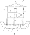
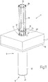
- Number 1 in Figure 1 indicates as a whole a building resting on the ground 2 on a foundation structure 3, and to be raised with respect to ground 2.
- Building 1 comprises a number of supporting walls 4, each of which rests on foundation structure 3, extends up to a roof 5, and supports three floors 6.
- Building 1 also comprises a number of non-supporting walls not shown in the drawings.
- a survey is made of building 1 to determine the distribution of the masses it is composed of. This consists of a graphic representation of the plan at various levels, and of all the masonry structures, including door and window openings and any damage to the masonry. Given the thickness and density of the masonry structures, it is possible to determine their weight and distribution.
- Building 1 is also analysed statically to make sure it can withstand minor stress induced by the lift, and may be consolidated and reinforced, if necessary, before the actual lift.
- ground 2 under building 1 is then examined to determine exactly what can be expected down to a depth of at least 5 m below level zero. Knowing the nature of ground 2 under building 1 is necessary to choose the type of foundation to construct (e.g. long piles, short piles or even footings).
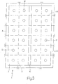
- a reinforcing mat 7 (or, more generally speaking, another type of foundation structure) is first constructed, and which forms part of a new foundation structure of building 1, extends over at least the whole base of building 1, and is made of post-tensioned reinforced concrete.
- reinforcing mat 7 is made of normal (i.e. non-prestressed) reinforced concrete.
- ground 2 is normally excavated to a depth at least equal to the thickness of mat 7; and mat 7 is designed rigid and strong enough to absorb the stress produced by eccentricity of the bottom reactions and the distribution of the loads transmitted by supporting walls 4.
- Mat 7 is typically constructed in portions extending between the walls. To achieve structural continuity between the various portions of mat 7 and supporting walls 4, mat 7 is post-tensioned by means of a number of metal post-tensioning cables 8 (shown by dash lines in Figures 2 and 3 ), each of which is embedded in mat 7 and inserted through respective through holes (not shown) in supporting walls 4. By virtue of post-tensioning cables 8, the various portions of mat 7 tighten supporting walls 4 to one another to achieve substantial structural continuity, so that flexural and shear continuity are established by the supporting walls 4 themselves interposed between adjacent portions of mat 7. In a different embodiment not shown, post-tensioning cables 8 are replaced by similar high-tensile steel bars or sections.
- foundation piles 9 shown for example in Figures 4 and 5
- anchoring pile-driving devices 10 one of which is shown in Figure 5
- anchoring lifting devices 11 one of which is shown in Figure 9 .
- Foundation piles 9 are distributed over the area of building 1 to balance as best as possible the weight of building 1 and mat 7.
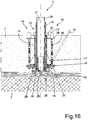
- mat 7 comprises a vertical hole 12 (of cylindrical or other section) lined with a metal guide tube 13, which is fixed to mat 7 by at least one metal fastening ring 14 embedded in mat 7, and has a top portion projecting upwards from mat 7.
- a layer 15 of relatively so-called lean concrete is preferably interposed between mat 7 and ground 2.
- Fastening ring 14 is normally located close to ground 2, i.e. at the bottom of mat 7.
- One fastening ring 14 is normally enough, though a number of fastening rings 14 may be provided at different levels.
- Each hole 12 is surrounded with a number of threaded anchoring ties 16, each of which is connected to fastening ring 14, extends through mat 7, and projects vertically outwards of mat 7.
- a connector 17 ( Figures 8 and 11 ) is screwed to the top portion of each anchoring tie 16 projecting outwards of mat 7, and may be screwed, on the opposite side, with an extension of anchoring tie 16.
- Anchoring ties 16 are equally spaced about hole 12, and normally number from 6 to 12 for each hole 12. It should be pointed out, however, that, in certain situations, two anchoring ties 16 for each hole 12 may be sufficient.
- each foundation pile 9 is a metal pile, and comprises a substantially constant-section shaft 18 normally defined by a number of tubular segments of equal length joined end to end (normally by a cold-force-fitted connecting sleeve or welded with a connecting sleeve in between); and a wide bottom foot 19 defining the bottom end of foundation pile 9.
- Shaft 18 may obviously be other than circular in section, and may be solid, e.g. may be defined by an I-beam.
- Each shaft 18 is tubular, has a through inner conduit 20, and is smaller crosswise than relative hole 12 to fit relatively easily through hole 12.
- Each foot 19 is defined by a flat, substantially circular plate 21 with a jagged outer edge, but may obviously be defined by a flat plate 21 of a different shape, e.g. oval, square or rectangular, with a jagged or smooth edge.
- Each foot 19 is larger than or the same size crosswise as relative hole 12, is initially separate from shaft 18, and, when constructing mat 7, is placed substantially contacting ground 2 beneath mat 7 and coaxial with hole 12. Each shaft 18 therefore only engages foot 19 to form foundation pile 9 when shaft 18 is inserted through hole 12.
- each connecting member 22 is defined by a cylindrical tubular member, which extends perpendicularly upwards from plate 21, and is sized to relatively loosely engage a bottom portion of inner conduit 20 of shaft 18.
- connecting member 22 may be formed differently.
- each guide tube 13 is fitted with at least one sealing ring 23 made of elastic material, and which engages the outer cylindrical surface of shaft 18 of foundation pile 9, when foundation pile 9 is fitted through corresponding hole 12.
- At least one injection conduit 24 is formed at each hole 12, is defined by a metal tube extending through mat 7, and has a top end projecting from mat 7, and a bottom end terminating adjacent to hole 12 and contacting a top surface of plate 21 of foot 19.
- a foundation pile 9 is driven into ground 2 through each hole 12. More specifically, one foundation pile 9 is driven at a time, or at any rate a small number of foundation piles 9 are driven simultaneously, to minimize stress on mat 7.
- each foundation pile 9 is assigned a rated load, i.e. a weight that must be supported by foundation pile 9 without yielding, i.e. without breaking and/or sinking further into ground 2.
- a rated load i.e. a weight that must be supported by foundation pile 9 without yielding, i.e. without breaking and/or sinking further into ground 2.
- each foundation pile 9 is normally driven until it is unable to withstand thrust by pile-driving device 10 greater than the rated load without sinking further into ground 2.
- This operating mode is made possible by driving one foundation pile 9 at a time into ground 2, so that, when driving in foundation pile 9, practically the whole weight of mat 7 and building 1 can be used as a reaction force to the thrust of pile-driving device 10.
- each foundation pile 9 is driven with a force equal to 1.5-3 times the rated load of foundation pile 9, thus ensuring maximum safety of building 1 both during and at the end of the lift.
- the load of each foundation pile 9 is tested before the lift, by subjecting it to 1.5-3 times the rated load, to allow foundation pile 9 to mature.
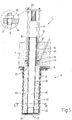
- pile-driving device 10 is set up over foundation pile 9, cooperates with the top end of foundation pile 9, and is connected to ties 16.
- pile-driving device 10 may be connected to guide tube 13.
- pile-driving device 10 comprises a hydraulic jack 25 located between the top end of foundation pile 9 and a top plate 26, which is fitted through with ties 16, and has a number of through holes 27 to slide freely along ties 16. Upward slide of top plate 26 is arrested by a number of nuts 28 screwed to ties 16 over top plate 26 using a torque wrench, so nuts 28 are all tightened equally and so act symmetrically and in balanced manner.
- pile-driving device 10 is operated to expand and exert static thrust on foundation pile 9 to drive foundation pile 9 into ground 2.
- the reaction force to the thrust exerted by pile-driving device 10 is provided by the weight of mat 7 and building 1, and is transmitted by ties 16, which act as reaction members by maintaining a fixed distance between top plate 26 and mat 7 as hydraulic jack 25 expands, thus driving in foundation pile 9.
- pile-driving device 10 may be formed differently, providing it exerts static thrust on foundation pile 9 to drive foundation pile 9 into ground 2.
- pile-driving device 10 may be of the type described in Patent Application IT2004B000792 , which is included herein by way of reference.
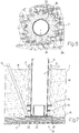
- foot 19 forms in ground 2 a channel 29 of substantially the same transverse shape and size as foot 19, and which comprises an inner cylindrical portion engaged by shaft 18, and a substantially clear outer tubular portion.
- substantially plastic cement material 30 is pressure-injected along injection conduit 24 into the outer tubular portion of channel 29. More specifically, cement material 30 is substantially defined by microconcrete for fluidity and smooth pressure-injection along injection conduit 24. Sealing ring 23 prevents the pressure-injected cement material 30 from leaking upwards through the gap between the outer surface of shaft 18 and the inner surface of guide tube 13.
- ground 2 has a tendency to shrink (as in the case of peat layers)
- substances e.g. bentonite
- cement material 30 may be added to cement material 30 to reduce friction (and therefore adhesion) of ground 2 with respect to cement material 30 as it dries, and so allow ground 2 to shrink freely and naturally with time.
- Waterproofing substances may also be added to cement material 30 to make it substantially waterproof even prior to curing. This is necessary when foundation pile 9 is sunk through groundwater, particularly high-pressure and/or relatively fast-flowing groundwater, and prevents cement material 30 from being washed away and so degraded. Tests also show that, when working through groundwater, it is important to inject cement material 30 at higher than the water pressure, to avoid the formation of breaks in cement material 30.
- each shaft 18 is divided into segments, which are driven successively, as described above, through hole 12 and joined to one another. More specifically, once a first segment of shaft 18 is driven, pile-driving device 10 is detached from the top end of the first segment to insert a second segment, which is joined end to end to the first (typically using a cold-force-fitted connecting sleeve, or welded with a connecting sleeve in between); and pile-driving device 10 is then connected to the top end of the second segment to continue the driving cycle.
- the segments forming each shaft 18 are normally identical, but, in certain situations, may differ in length, shape or thickness.
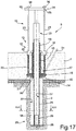
- each foundation pile 9 is fitted with a lifting device 11 resting on the top end of foundation pile 9 on one side, and connected to ties 16 on the other side.
- each lifting device 11 is operated to produce, between foundation pile 9 and mat 7, static thrust which is transmitted to mat 7 by ties 16.
- each lifting device 11 comprises a hydraulic jack 31 in turn comprising a cylinder 32, from the top end of which extends a movable rod 33.
- Each hydraulic jack 31 is located between a bottom plate 35 - which rests on the top end of foundation pile 9, is fitted through with ties 16, and has a number of through holes 36 to slide freely along ties 16 - and top plate 26, which is fitted through with ties 16 and has a number of through holes 27 to slide freely along ties 16.
- Upward slide of top plate 26 is arrested by a number of nuts 28 screwed to ties 16 over top plate 26.
- At least one Belleville washer 34 is preferably interposed between each nut 28 and top plate 26, and deforms elastically to allow top plate 26 to tilt slightly with respect to ties 16.
- each hydraulic jack 31 is operated to expand and so exert thrust, between foundation pile 9 and mat 7, which is transmitted to mat 7 by ties 16, which act as reaction members by maintaining a fixed distance between top plate 26 and mat 7 as hydraulic jack 31 expands.
- ties 16 are fitted with safety nuts 37 located over and kept close to bottom plate 35 to limit downward travel of mat 7 in the event of a breakdown (hydraulic failure, resulting in loss of pressure, or mechanical failure) of hydraulic jack 31.
- Safety nuts 37 are preferably tightened using a torque wrench, so they are all tightened equally and so function symmetrically and in balanced manner.
- each foundation pile 9 may be either a one-piece body, or comprise a number of connected tubular segments, which are inserted successively through hole 12 and joined to one another as building 1 is raised with respect to ground 2.
- lifting device 11 is detached from the top end of the first segment to insert a second segment, which is butt welded to the first (possibly with a connecting piece in between); and lifting device 11 is then connected to the top end of the second segment to continue the lift cycle.
- foundation piles 9 and lifting devices 11 are divided into three equal, symmetrical, independent work groups (shown by dash lines in Figure 12 and indicated by Roman numerals I, II, III).
- the work groups should be as equal as possible, i.e. should comprise roughly the same number of lifting devices 11, and be as symmetrical as possible, i.e. the thrust barycentres A of the three work groups should correspond to the vertices of a preferably equilateral triangle with its centre at the barycentre B of the weight of building 1 and mat 7.
- the above requirements in terms of equality and symmetry of the three work groups are not strictly mandatory, but should be complied with as closely as possible to minimize mechanical stress of building 1.
- Lifting devices 11 of each work group are connected to a respective hydraulic central control unit 38, which supplies all the hydraulic jacks 31 and can cut of pressurized-oil supply to each hydraulic jack 31 individually.
- each hydraulic central control unit 38 supplies all the hydraulic jacks 31 in its own group with pressurized oil pumped by an oil pump (not shown), and can also cut off pressurized-oil supply to one or more hydraulic jacks 31 by closing respective on-off solenoid valves (not shown). It is important to note that hydraulic central control unit 38 of one work group is independent of hydraulic central control units 38 of the other work groups.
- Each hydraulic jack 31 is connected to a respective linear position sensor 39 (typically a linear encoder) shown schematically in Figure 10 , and which measures the relative position (i.e. distance) between the top surface of mat 7 and bottom plate 35 to real-time measure the actual lift of mat 7.
- Each linear position sensor 39 may, for example, be located between a tie 16 and bottom plate 35.
- each linear position sensor 39 measures the position of rod 33 with respect to cylinder 32 of respective hydraulic jack 31 to real-time measure the actual expansion of hydraulic jack 31, which is related to the actual lift of mat 7.
- a common linear position sensor 39 may be connected to a close group of hydraulic jacks 31 to reduce the number of linear position sensors 39 required and so reduce cost and simplify the system.
- building 1, reinforced with mat 7, must be thought of as resting on three points (thrust barycentres A) having a spherical hinge (simulated by Belleville washers 34), so that lifting can be performed by activating one work group at a time, and the whole building 1 rotates about the axis through thrust barycentres A of the other two idle work groups, without producing any hyperstatic constraints.
- Building 1 is normally raised at a very slow speed (calculated at thrust barycentres A of the three work groups) to maintain isostatic conditions.
- Working at slow speed ensures a wide margin of safety during the lift, in that, by totally eliminating dynamic forces, reference can be made to static-condition standards.
- the lift can be interrupted at any time to monitor, calibrate or make changes to the electric control system or hydraulic system.
- building 1 normally tilts by fractions of a degree with respect to the vertical.
- the building 1 weight force component along the tilt plane is very small, and can easily be balanced (if necessary) by means of ties activated by hydraulic compensating jacks.
- the system is monitored constantly by a control unit 40 connected to pressure sensors 41 for measuring the actual pressure of hydraulic central control units 38, to position sensors 39 to measure the actual extension of each hydraulic jack 31, and to a number of wide-base strain gauges 42 fitted to supporting walls 4 of building 1 to measure the stress induced by the lift on supporting walls 4.
- a control unit 40 connected to pressure sensors 41 for measuring the actual pressure of hydraulic central control units 38, to position sensors 39 to measure the actual extension of each hydraulic jack 31, and to a number of wide-base strain gauges 42 fitted to supporting walls 4 of building 1 to measure the stress induced by the lift on supporting walls 4.
- flat measuring jacks may be inserted inside supporting walls 4 (e.g. by temporarily removing the mortar between two superimposed bricks in the walls to form a gap in which to insert the flat measuring jacks).
- pressure sensors record the fluid pressure in the flat measuring jacks to accurately determine instantaneous compression on supporting walls 4, and so detect any unusual or excessive increase in compression on each supporting wall 4 when raising building 1.
- control unit 40 monitors flexural deformation of mat 7 by means of a main system defined by the inclinometers, and by means of a redundant secondary system defined by the precision optical device.
- flexural deformation of mat 7 must be maintained within a very small range and, above all, absolutely stable throughout the lift, on account of it depending substantially on the inevitable distances (which remain constant at all times) between the weight distribution of building 1 and the thrust of lifting devices 11. If a predetermined maximum flexural deformation of mat 7 is exceeded during the lift, the thrust of lifting devices 11 must be balanced better.
- Further trimming of mat 7 may be achieved by adjusting opposite posttensioning cables 8 capable of producing predetermined reactions.
- control unit 40 controls respective hydraulic central control unit 38 to operate one group of lifting devices 11 at a time.
- control unit 40 establishes a lift value (normally 0.5-50 mm) for each lift step, and controls hydraulic central control unit 38 so that each hydraulic jack 31 in the group expands by exactly the predetermined lift step value.
- control unit 40 controls hydraulic central control unit 38 to cut off oil supply to and stop expansion of hydraulic jack 31.
- control unit 40 feedback controls each hydraulic jack 31 using the actual lift step value as a feedback variable.
- the same predetermined lift step value is determined for all the hydraulic jacks 31, and expansion of each hydraulic jack 31 is stopped when the actual lift step value (measured by respective position sensor 39) equals the predetermined value.
- each hydraulic jack 31 By controlling each hydraulic jack 31 to expand by exactly the predetermined lift step value, it is not essential (though preferable to reduce mechanical stress on building 1) that the three work groups be as equal as possible, i.e. comprise roughly the same number of lifting devices 11, and be as symmetrical as possible, i.e. that the thrust barycentres A of the three work groups correspond to the vertices of a triangle with its centre at the barycentre B of the weight of building 1 and mat 7.
- lifting devices 11 are divided into a different number of groups, each comprising at least one lifting device 11.
- lifting devices 11 are operated individually (i.e. each group comprises one lifting device 11) or in small groups, each comprising a small number of (3-7) closely grouped lifting devices 11, so that each expands by exactly the predetermined lift step value at each lift step.
- the lift of building 1 is divided into a number of successive lift steps, during each of which, hydraulic jacks 31 are all controlled to expand by exactly the predetermined lift step value as described above.
- a small group i.e.
- each lift step provides for a very small amount of lift, normally, ranging between 0.5 and 50 mm, to ensure very little stress on building 1 during the lift.
- each lifting device 11 is running, the hydraulic pressure of the corresponding hydraulic jack 31 is recorded, and pressurized-fluid supply to hydraulic jack 31 of the currently operating lifting device 11 is cut off if the hydraulic pressure of hydraulic jack 31 exceeds a predetermined maximum threshold value, so as to avoid overloading lifting device 11 and the structures acted on by lifting device 11 during the lift.
- One embodiment not shown also employs external position sensors independent of lifting devices 11 to accurately measure the actual lift of building 1.
- These position sensors measure the absolute displacement of mat 7 with respect to ground 2, and comprise a first part integral with ground 2, and a second part integral with mat 7.
- the lift measured by the external position sensors is exact, and may differ from the lift recorded by position sensors 39 fitted to hydraulic jacks 31, in that expansion of each hydraulic jack 31 may partly lift mat 7 and partly produce further sinking and/or deformation of foundation pile 9.
- each foundation pile 9 is filled with substantially plastic "concrete" 43.
- foundation pile 9 is fixed axially to mat 7 by securing (normally welding) to the top wall of slide tube 13 a circular or annular fastening plate 44 which is placed on top, to engage the top end, of foundation pile 9, so that the top end of foundation pile 9 rests against fastening plate 44 which is integral with slide tube 13.
- each foundation pile 9 may be filled with concrete 43 before commencing the lift, so that, when raising the building, each pile 9 is capable of supporting a greater load without yielding and/or deforming.
- a body of elastic material e.g. neoprene
- slide tube 15 between the top end of foundation pile 9 and fastening plate 47, normally to enhance the antiseismic characteristics of mat 7.
- Each foundation pile 9 may also be fixed axially to mat 7 removably, to permit further lift of building 1 in the future.
- each foundation pile 9 is driven so that the top end is below the top surface of mat 7, and fastening plate 47 is substantially flush with the top surface of mat 7 when fixed to the top wall of slide tube 15, so the whole top surface of mat 7 can be walked on.
- foundation pile 9 Before being fixed axially to mat 7, foundation pile 9 can be preloaded with a downward thrust of given intensity for as long as necessary to weld fastening plate 44 to guide tube 13. In other words, when welding fastening plate 44 to guide tube 13, downward thrust of given intensity is applied to foundation pile 9. Preloading foundation pile 9 when fixing it to mat 7 allows any yield of foundation pile 9 to emerge immediately as opposed to over the long term; the reason obviously being that correcting yield of one or more foundation piles 9 during installation is relatively cheap and straightforward, whereas doing it at the end of the job is much more complicated and expensive.
- mat 7 rests on a further foundation mat 45 having a large number of piles 46 driven into ground 2 beneath a stream or basin of water (e.g. a lagoon) 47.
- a stream or basin of water e.g. a lagoon
- This solution is typical of a building 1 built on water, wherein piles 46 are driven into ground 2 beneath, and support building 1 above, the level of water 47.
- the feet 19 of at least some of foundation piles 9 obviously rest on further mat 45; in which case, the foundation piles 9 resting on further mat 45 are obviously not driven into ground 2.
- foundation piles 9 (and hence mat 7) rest on further foundation piles driven beforehand, or on any other type of existing support under foundation mat 7.
- feet 26 of at least some of foundation piles 9 rest on further foundation piles driven beforehand, or on any other type of existing support under foundation mat 7.
- ground 2 and any existing foundation structures underneath mat 7 are removed, so that mat 7 and the whole of building 1 above the underside of mat 7 are supported solely by foundation piles 9.
- everything mat 7 rests on (ground 2 and any existing foundation structures), i.e. everything beneath mat 7, is removed before raising building 1 with respect to ground 2, so that, before raising building 1 with respect to ground 2, mat 7 and the whole of building 1 above the underside of mat 7 are supported solely by foundation piles 9.
- FIG. 15 As shown in Figure 15 , once the building is raised, continuity between the old foundation structure 3 and supporting walls 4 of building 1 may be restored by additional masonry 48.
- This ensures greater safety and endurance, by providing building 1 with two foundation systems, each capable of supporting building 1 on its own.
- flat jacks 49 are interposed between additional masonry 48 and supporting walls 4 of building 1, and are expanded to at least partly load the old foundation structure 3.
- Each flat jack 49 comprises two metal sheets welded to each other to form a pocket in between, which is filled with pressurized fluid to expand flat jack 49.
- the fluid used to fill the pocket of flat jack 49 is preferably a resin that tends to set with time to stabilize the situation regardless of the endurance of the pocket.
- mat 7 is constructed entirely just before the lift. In an alternative embodiment, at least part of mat 7 may already be built; in which case, holes 12 are core-drilled.
- building 1 has only supporting walls 4.
- building 1 may also have other supporting members (typically, supporting pillars) together with or instead of supporting walls 4.
- the lifting method described above may obviously be used to advantage to raise any type of building structure other than a building, e.g. a bridge.
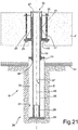
- mat 7 comprises a vertical hole 12 (of cylindrical or other section) lined with a metal guide tube 13, which has a top portion projecting upwards from mat 7, and an anchoring flange 14 embedded in a bottom portion of mat 7 and fixed (typically welded) centrally to an outer surface of guide tube 13.
- Each guide tube 13 is housed inside a slide tube 15 which is coaxial with and surrounds guide tube 13, and is axially slidable with respect to guide tube 13 to slide axially with respect to guide tube 13 and integrally with mat 7 when raising mat 7 with respect to ground 2 (as described in detail below). It is important to note that whereas a top portion of each guide tube 13 projects upwards from mat 7, each slide tube 15 is flush with mat 7; and each guide tube 13 extends downwards to a bottom wall of mat 7, whereas the bottom of each slide tube 15 stops short of the bottom wall of mat 7.
- Each slide tube 15 has an annular bottom anchoring flange 16 embedded in mat 7, above anchoring flange 14 of guide tube 13, and fixed (normally welded) centrally to an outer surface of slide tube 15.
- anchoring flange 14 of each guide tube 13 is located beneath slide tube 15, and rests on a bottom wall of slide tube 15.
- anchoring flange 14 also provides for sealing off the bottom of the annular gap between the outer surface of guide tube 13 and the inner surface of slide tube; 15, and so keeping out impurities (such as water, concrete, etc.).
- Each bottom anchoring flange 16 preferably has a number of (e.g. six) braces 17, which are arranged radially and symmetrically about slide tube 15, are right-triangular in shape, and are fixed (normally welded) to an outer surface of slide tube 15 and to a top surface of bottom anchoring flange 16.
- braces 17 which are arranged radially and symmetrically about slide tube 15, are right-triangular in shape, and are fixed (normally welded) to an outer surface of slide tube 15 and to a top surface of bottom anchoring flange 16.
- Each slide tube 15 also has an annular top locating flange 18 embedded in mat 7 and fixed (normally welded) centrally to an outer surface of slide tube 15.
- at least one intermediate anchoring flange may be provided between bottom anchoring flange 16 and top locating flange 18.
- Each through hole 12 is surrounded by a number of (e.g. six) anchors 19 arranged axially and symmetrically about slide tube 15 (i.e. about guide tube 13), projecting upwards from mat 7, and fastened to slide tube 15.
- Anchors 19 are defined by respective threaded metal bars 20 fitted through top locating flange 18 of slide tube 15 and fastened to bottom anchoring flange 16 of slide tube 15.
- bottom anchoring flange 16 has a through hole through which bar 20 is fitted; and a bottom end of bar 20 has a nut 21 which is screwed to bar 20 to prevent it sliding upwards.
- top locating flange 18 has a through hole through which bar 20 is fitted; and to the top portion of each bar 20 above top locating flange 18 is screwed a connecting sleeve 22 by which to fasten stays 23 ( Figure 17 ) to'bars 20, i.e. to anchors 19.
- each anchor 19 i.e. connecting sleeve 22
- a protective cover e.g. a tubular member of foam rubber or similar, to prevent the concrete pour of mat 7 from fouling the top end of each anchor 19.
- Each slide tube 15 preferably has a sealing ring 24 which is fixed (normally welded) to slide tube 15, is located at the top of slide tube 15 (i.e. contacting a top wall of slide tube 15), and rests internally on an outer surface of guide tube 13 to seal the top of the annular gap between the outer surface of guide tube 13 and the inner surface of slide tube 15 and so keep out any impurities (such as dust, water, concrete, etc.).
- a sealing ring 24 which is fixed (normally welded) to slide tube 15, is located at the top of slide tube 15 (i.e. contacting a top wall of slide tube 15), and rests internally on an outer surface of guide tube 13 to seal the top of the annular gap between the outer surface of guide tube 13 and the inner surface of slide tube 15 and so keep out any impurities (such as dust, water, concrete, etc.).
- Each foundation pile 9 is a metal pile, and comprises a substantially constant-section shaft 25 normally defined by a number of tubular segments of equal length connected end to end (normally using cold-force-fitted connecting sleeves, or welded with connecting sleeves in between); and a wide bottom foot 26 defining the bottom end of foundation pile 9.
- Shaft 25 may obviously be other than circular in section, and may be solid, e.g. defined by an I-beam.
- Each shaft 25 is tubular, has a through inner conduit 27, and is smaller across (in diameter) than the inside hole of relative guide tube 13 to fit relatively easily through, guide tube 13.
- Each foot 26 is defined by a flat, substantially circular plate 28 with a preferably jagged outer edge. Flat plate 28, however, may obviously be shaped differently, e.g. oval, square or rectangular, with a jagged or smooth edge.
- Each foot 26 is larger across (in diameter) than shaft 25, is normally larger across (in diameter) than the inside hole of relative guide tube 13, is initially separate from shaft 25, and, when constructing mat 7, is placed substantially contacting ground 2 beneath mat 7 and coaxial with through hole 12, so that shaft 25 only engages foot 26 to form foundation pile 9 when shaft 25 is inserted through hole 12.
- each connecting member 29 is defined by a cylindrical tubular member, which extends perpendicularly upwards from plate 28, and is sized to relatively loosely engage a bottom portion of inner conduit 27 of shaft 25.
- each guide tube 13 is fitted with at least one sealing ring 30 made of elastic material, and which is fixed to an inner wall of guide tube 13, is located, between an inner wall of guide tube 13 and an outer wall of foundation pile 9, and presses against an outer surface of shaft 25 of foundation pile 9, as foundation pile 9 is driven in, to prevent extraneous material from working its way up inside the annular gap between the inner wall of guide tube 13 and the outer wall of foundation pile 9.
- sealing ring 30 may be eliminated.
- At least one injection conduit 31 is formed at each hole 12, is defined by a metal tube extending through mat 7, and has a top end projecting from mat 7, and a bottom end terminating adjacent to hole 12 and contacting a top surface of plate 28 of foot 26 of foundation pile 9.
- a layer 32 of relatively poor, so-called “lean”, concrete is preferably interposed between mat 7 and ground 2, so plate 28 of foot 26 of foundation pile 9 rests on "lean” concrete layer 32.
- a foundation pile 9 is driven into ground 2 through each hole 12. More specifically, one foundation pile 9 is driven at a time, or at any rate a small number of foundation piles 9 are driven simultaneously, to minimize stress on mat 7.
- each foundation pile 9 is assigned a rated load, i.e. a weight foundation pile 9 must be capable of supporting without yielding, i.e. without breaking and/or sinking further into ground 2.
- a rated load i.e. a weight foundation pile 9 must be capable of supporting without yielding, i.e. without breaking and/or sinking further into ground 2.
- each foundation pile 9 is normally driven until it is unable to withstand, thrust by pile-driving device 10 greater than the rated load without sinking further into ground 2.
- This operating mode is made possible by driving one foundation pile 9 at a time into ground 2, so that, when driving in foundation pile 9, practically the whole weight of mat 7 and building 1 can be used as a reaction force to the thrust of pile-driving device 10.
- pile-driving device 10 is set up over foundation pile 9, cooperates with the top end of foundation pile 9, and is anchored to stays 23 to make it integral with mat 7.
- pile-driving device 10 may be anchored to guide tube 13 to make it integral with mat 7.
- pile-driving device 10 comprises a hydraulic jack 33 located between the top end of foundation pile 9 and a top plate 34, whichi is fitted through with stays 23, and has a number of through holes 35 to slide freely along stays 23. Upward slide of top plate 34 is arrested by a number of nuts 36 screwed using a torque wrench to stays 23 over top plate 34, so nuts 36 are all tightened equally and so act symmetrically and in balanced manner.
- pile-driving device 10 is operated to expand and exert static thrust on foundation pile 9 to drive it into ground :2.
- the reaction force to the thrust exerted by pile-driving device 10 is provided by the weight of mat 7 and building 1, and is transmitted by stays 23, which act as reaction members by maintaining a fixed distance between top plate 34 and mat 7 as hydraulic jack 33 expands, thus driving in foundation pile 9.
- pile-driving device 10 may be formed differently, providing it exerts static thrust on foundation pile 9 to drive it into ground 2.
- pile-driving device 10 may be of the type described in Patent Application WO2007071783A1 , which is included herein by way of reference.
- foot 26 forms in ground 2 a channel 37 of substantially the same shape and transverse size as foot 26.
- substantially plastic concrete 38 is pressure-injected along injection conduit 31 into channel 37. More specifically, concrete 38 is substantially defined by microconcrete for fluidity and smooth pressure-injection along injection conduit 31. Sealing ring 30 prevents pressure-injected concrete 38 from leaking upwards inside the gap between the outer surface of shaft 25 and the inner surface of guide tube 13.
- additives may be added to concrete 38 to reduce friction (and therefore adhesion) of ground 2 with respect to concrete 38 after it sets, and so allow ground 2 to shrink freely and naturally with time.
- Waterproofing additives may be added to concrete 38 to make it substantially waterproof even prior to curing. This is necessary when foundation pile 9 is sunk through groundwater, particularly high-pressure and/or relatively fast-flowing groundwater, and prevents concrete 38 from being washed away and so degraded. Tests show that, when working through high-pressure groundwater, it is important to inject concrete 38 at higher than the water pressure, to avoid the formation of breaks in concrete 38.
- each shaft 25 is divided into segments, which are driven successively, as described above, through hole 12 in mat 7, and are joined together using cold-force-fitted connecting sleeves or welded with connecting sleeves in between. More specifically, once a first segment of shaft 25 is driven, pile-driving device 10 is detached from the top end of the first segment to insert a second segment, which is joined to the first segment using a cold-force-fitted connecting sleeve or butt welded with a connecting, sleeve in between; and pile-driving device 10 is then connected to the top end of the second segment to continue the driving cycle.
- the segments of each' shaft 25 are normally identical, but, in certain situations, may differ in length, shape or thickness.
- each foundation pile 9 comprises at least one further, lead-in, foot coaxial with and beneath foot 26, which has a central opening; and the lead-in foot comprises an elongated body extending upwards through the central opening in the main foot to engage the bottom end of shaft 25.
- each foundation pile 9 is fitted with a lifting device 11 resting on the top end of foundation pile 9 on one side, and connected to stays 23 on the other side.
- each lifting device 11 is operated to produce, between foundation pile 9 and mat 7, static thrust which is transmitted to mat 7 by stays 23 acting as reaction members.
- drive-in thrust is only applied to shaft 25 of foundation pile 9
- lift thrust is applied to both shaft 25 of foundation pile 9 and the corresponding guide tube 13, until guide tube 13 projects from the top of mat 7.
- this therefore slides axially with respect to guide tube 13, which remains stationary and integral with mat 7; whereas, when raising (or at least initially raising) the building, guide tube 13 slides axially with respect to slide tube 15, which remains stationary and integral with mat 7.
- each lifting device 11 comprises a hydraulic jack 39 in turn comprising a cylinder 40, from the top end of which extends a movable rod 41.
- Each hydraulic jack 39 is located between a bottom plate 43 - which rests on the top end of foundation pile 9, is fitted through with stays 23, and has a number of through holes 44 to slide freely along stays 23 - and top plate 34, which is fitted through with stays 23, and has a number of through holes 35 to slide freely along stays 23.
- Upward slide of top plate 34 is arrested by a number of nuts 36 screwed to stays 23 over top plate 34.
- At least one Belleville washer 42 is preferably interposed between each nut 36 and top plate 34, and, as it deforms elastically, allows top plate 34 to tilt slightly with respect to stays 23.
- each hydraulic jack 39 is operated to expand and so exert thrust, between foundation pile 9 and mat 7, which is transmitted to mat 7 by stays 23, which act as reaction members by maintaining a fixed distance between top plate 34 and mat 7 as hydraulic jack 39 expands.
- stays 23 are fitted with safety nuts 45 located over and kept close to bottom plate 43 to limit downward travel of mat 7 in the event of a breakdown (hydraulic failure, resulting in loss of pressure, or mechanical failure) of hydraulic jack 39.
- Safety nuts 45 are preferably tightened using a torque wrench, so safety nuts 45 are all tightened equally and, when necessary, act symmetrically and in balanced manner.
- hydraulic jacks 39 can be operated to commence raising building 1.
- shaft 25 of each foundation pile 9 may be fitted with one or more additional tubular segments, which are gradually inserted through hole 12 as building 1 is raised with respect to ground 2, and are joined end to end as described previously.
- lifting device 11 is detached from the top end of the first segment to insert a second segment, which is butt welded to the first segment (possibly with a connecting piece in between); after which, lifting device 11 is connected to the top end of the second segment to continue the lift cycle.
- each foundation pile 9 is filled with substantially plastic "concrete" 46.
- foundation pile 9 is fixed axially to mat 7 by securing (normally welding) to the top wall of slide tube 15 a circular or annular fastening plate 47 which is placed on top, to engage the top end, of foundation pile 9, so that the top end of foundation pile 9 rests against fastening plate 47 which is integral with slide tube 15.
- each foundation pile 9 may be filled with concrete 46 before commencing the lift, so that, when raising the building, each pile 9 is capable of supporting a greater load without yielding and/or deforming.
- a body of elastic material e.g. neoprene
- slide tube 15 between the top end of foundation pile 9 and fastening plate 47, normally to enhance the antiseismic characteristics of mat 7.
Applications Claiming Priority (3)
| Application Number | Priority Date | Filing Date | Title |
|---|---|---|---|
| IT000857A ITBO20070857A1 (it) | 2007-12-31 | 2007-12-31 | Metodo per sollevare un manufatto edilizio |
| ITBO2008A000537A IT1397314B1 (it) | 2008-09-03 | 2008-09-03 | Metodo ed impianto di sollevamento per sollevare un manufatto edilizio |
| PCT/IB2008/003653 WO2009087469A2 (en) | 2007-12-31 | 2008-12-30 | Method and system for raising a building structure |
Publications (2)
| Publication Number | Publication Date |
|---|---|
| EP2231935A2 EP2231935A2 (en) | 2010-09-29 |
| EP2231935B1 true EP2231935B1 (en) | 2019-09-04 |
Family
ID=40585589
Family Applications (1)
| Application Number | Title | Priority Date | Filing Date |
|---|---|---|---|
| EP08869988.9A Active EP2231935B1 (en) | 2007-12-31 | 2008-12-30 | Method for raising a building structure |
Country Status (5)
| Country | Link |
|---|---|
| US (1) | US8926227B2 (zh) |
| EP (1) | EP2231935B1 (zh) |
| CN (1) | CN101939493B (zh) |
| BR (1) | BRPI0819592A2 (zh) |
| WO (1) | WO2009087469A2 (zh) |
Families Citing this family (22)
| Publication number | Priority date | Publication date | Assignee | Title |
|---|---|---|---|---|
| US8458984B2 (en) * | 2009-07-28 | 2013-06-11 | Frederick S. Marshall | System and method for forming a movable slab foundation |
| CN102275593B (zh) * | 2010-06-11 | 2015-03-04 | 北京铁道工程机电技术研究所有限公司 | 一种高速动车组的地坑式架车机 |
| CZ304254B6 (cs) * | 2012-05-20 | 2014-01-29 | Eismann | Dřevostavba do povodňových a záplavových oblastí se systémem protipovodňové ochrany |
| ITMI20120916A1 (it) * | 2012-05-28 | 2013-11-29 | Setten Genesio S P A | Metodo per la sospensione temporanea di edifici esistenti per la realizzazione di sottofondazioni/sottocostruzioni di detti edifici. |
| CN102733615B (zh) | 2012-07-12 | 2014-10-15 | 广州建筑股份有限公司 | 非对称整体提升施工方法 |
| CN103046576B (zh) * | 2013-01-18 | 2015-01-07 | 上海建筑设计研究院有限公司 | 高精密设备的桩基及其基础底板微变形和振动控制方法 |
| US9238920B1 (en) * | 2013-03-15 | 2016-01-19 | Flood Lift System Corporation | Liftable structure system |
| US9605404B2 (en) * | 2013-05-29 | 2017-03-28 | Glen G. Hale | High strain dynamic load testing procedure |
| CN104763005A (zh) * | 2015-03-18 | 2015-07-08 | 山东省水利科学研究院 | 大型钢制球罐纠倾方法 |
| US10508406B1 (en) | 2016-08-09 | 2019-12-17 | Tella Firma, Llc | Systems and methods for installing and stabilizing a pier |
| CN106193140A (zh) * | 2016-08-23 | 2016-12-07 | 上海长凯岩土工程有限公司 | 一种高层建筑物纠偏加固方法 |
| US10081925B2 (en) * | 2016-12-30 | 2018-09-25 | Edvard Amirian | Method for constructing building through gravity and weight of the building structure |
| NL2020037B1 (en) * | 2017-12-07 | 2019-06-19 | Ihc Holland Ie Bv | A coupling system, an assembly of a vessel and a coupling system, and an assembly of a coupling system, jacket pile and foundation pile |
| US10683659B2 (en) * | 2018-03-08 | 2020-06-16 | Raul S. Nieves | Method for raising a framed structure |
| US11313117B2 (en) | 2018-03-08 | 2022-04-26 | Raul S. Nieves | Method for raising a framed structure |
| US10422102B1 (en) * | 2018-03-22 | 2019-09-24 | Tella Firma, Llc | Systems and methods using expendable fluid drive actuators for foundation lifting |
| US10294628B1 (en) * | 2018-03-26 | 2019-05-21 | Tella Firma, Llc | Systems and methods for lifted foundation retention with locking cap |
| US11346099B2 (en) | 2018-12-31 | 2022-05-31 | Independence Materials Group, Llc | Apparatus and method for lifting a concrete slab |
| US10947694B2 (en) * | 2019-07-04 | 2021-03-16 | Korea Institute Of Civil Engineering And Building Technology | Preloading apparatus for adjusting load and method of reinforcing foundation using the same |
| US11060947B2 (en) | 2019-10-02 | 2021-07-13 | Grl Engineers, Inc. | Top loaded bidirectional testing system and method of using the same |
| CN111608203B (zh) * | 2020-06-02 | 2021-08-17 | 中国建筑工程(香港)有限公司 | 可进行缓冲的沉管沉放装置 |
| CN116290006B (zh) * | 2023-05-18 | 2023-09-08 | 中铁二十三局集团有限公司 | 一种复合防护材料基坑支护体系及施工方法 |
Family Cites Families (5)
| Publication number | Priority date | Publication date | Assignee | Title |
|---|---|---|---|---|
| CN1068085C (zh) * | 1997-07-23 | 2001-07-04 | 夏强 | 预加反力封桩施工方法及预加反力封桩加荷装置 |
| CN1262365A (zh) * | 1999-01-22 | 2000-08-09 | 高继良 | 建筑物抬升的方法及其使用装置 |
| US6923599B2 (en) * | 2002-06-24 | 2005-08-02 | Kenneth J. Kelso | In-ground lifting system and method |
| ITBO20040514A1 (it) | 2004-08-06 | 2004-11-06 | Mattioli Spa | Metodo per sollevare un manufatto edilizio ed in particolare per sollevare un manufatto edilizio soggetto ad allagamenti |
| ITBO20060414A1 (it) | 2006-05-26 | 2007-11-27 | Soles Societa Lavori Edili E Serbatoi Spa | Metodo per sollevare un manufatto edilizio. |
-
2008
- 2008-12-30 CN CN200880125742XA patent/CN101939493B/zh not_active Expired - Fee Related
- 2008-12-30 WO PCT/IB2008/003653 patent/WO2009087469A2/en active Application Filing
- 2008-12-30 EP EP08869988.9A patent/EP2231935B1/en active Active
- 2008-12-30 US US12/735,296 patent/US8926227B2/en active Active
- 2008-12-30 BR BRPI0819592A patent/BRPI0819592A2/pt not_active IP Right Cessation
Non-Patent Citations (1)
| Title |
|---|
| None * |
Also Published As
| Publication number | Publication date |
|---|---|
| CN101939493A (zh) | 2011-01-05 |
| US20120114423A1 (en) | 2012-05-10 |
| EP2231935A2 (en) | 2010-09-29 |
| US8926227B2 (en) | 2015-01-06 |
| CN101939493B (zh) | 2013-07-31 |
| BRPI0819592A2 (pt) | 2017-05-30 |
| WO2009087469A2 (en) | 2009-07-16 |
| WO2009087469A9 (en) | 2009-09-17 |
Similar Documents
| Publication | Publication Date | Title |
|---|---|---|
| EP2231935B1 (en) | Method for raising a building structure | |
| EP2021549B1 (en) | Method of raising a building | |
| US3852970A (en) | Building raising and underpinning system | |
| US7108458B1 (en) | Interlocking slab leveling system | |
| JP5277174B2 (ja) | リングセルを使用して荷重負担能力を試験する方法および装置 | |
| CN109356210B (zh) | 一种桩基建筑物纠倾截桩托换限位结构及其施工方法 | |
| US7909541B1 (en) | Apparatus and method for improved grout containment in post-grouting applications | |
| KR101882373B1 (ko) | 하중 지지력 시험 방법 및 장치 | |
| CN108842798B (zh) | 一种预制后浇筑式沉井的静压下沉施工方法 | |
| KR20120100052A (ko) | 유압잭을 이용한 측방유동교각 보정방법 및 세굴 보강구조 | |
| US11629473B2 (en) | Multiple friction joint pile system | |
| Edens et al. | Foundation retrofit of three structures utilizing micropiles | |
| CN108951684B (zh) | 周转型型钢混凝土施工电梯基础施工方法 | |
| EP1792019B1 (en) | Method of raising a building structure, in particular a building structure subject to flooding | |
| RU116516U1 (ru) | Конструкция усиления фундамента | |
| CN218911104U (zh) | 一种防止高架桥墩塌陷的平台结构 | |
| AU2019101315A4 (en) | A method and apparatus | |
| CN110823706B (zh) | 一种检测上下层预制构件竖向连接质量的装置及方法 | |
| CN115478548B (zh) | 膨胀土路堑边坡减胀抗震防灾组合支挡结构及施工方法 | |
| JP3930088B2 (ja) | スクリュージャッキと水圧ジャッキを併用した建築土木工事におけるジャッキ制御装置 | |
| CN109706848B (zh) | 一种利用穿心式千斤顶顶进桥涵的施工方法 | |
| Kolm et al. | Capacity of Hydraulically Jacked Piles | |
| CN116988457A (zh) | 既有建筑增设多层地下室钢管桩托换施工方法及结构 | |
| JPH08144255A (ja) | 杭の加力装置 | |
| CN116988480A (zh) | 软土地层超宽超深基坑施工方法 |
Legal Events
| Date | Code | Title | Description |
|---|---|---|---|
| PUAI | Public reference made under article 153(3) epc to a published international application that has entered the european phase |
Free format text: ORIGINAL CODE: 0009012 |
|
| 17P | Request for examination filed |
Effective date: 20100630 |
|
| AK | Designated contracting states |
Kind code of ref document: A2 Designated state(s): AT BE BG CH CY CZ DE DK EE ES FI FR GB GR HR HU IE IS IT LI LT LU LV MC MT NL NO PL PT RO SE SI SK TR |
|
| AX | Request for extension of the european patent |
Extension state: AL BA MK RS |
|
| DAX | Request for extension of the european patent (deleted) | ||
| RAP1 | Party data changed (applicant data changed or rights of an application transferred) |
Owner name: CONSTA S.P.A |
|
| RIN1 | Information on inventor provided before grant (corrected) |
Inventor name: ZAGO, ROBERTO Inventor name: MARABELLO, GIOACCHINO Inventor name: SCUTTARI, STEFANO Inventor name: ZAMBIANCHI, LAMBERTO |
|
| STAA | Information on the status of an ep patent application or granted ep patent |
Free format text: STATUS: EXAMINATION IS IN PROGRESS |
|
| 17Q | First examination report despatched |
Effective date: 20180227 |
|
| GRAP | Despatch of communication of intention to grant a patent |
Free format text: ORIGINAL CODE: EPIDOSNIGR1 |
|
| STAA | Information on the status of an ep patent application or granted ep patent |
Free format text: STATUS: GRANT OF PATENT IS INTENDED |
|
| INTG | Intention to grant announced |
Effective date: 20190325 |
|
| RIN1 | Information on inventor provided before grant (corrected) |
Inventor name: MARABELLO, GIOACCHINO Inventor name: ZAMBIANCHI, LAMBERTO Inventor name: SCUTTARI, STEFANO Inventor name: ZAGO, ROBERTO |
|
| RAP1 | Party data changed (applicant data changed or rights of an application transferred) |
Owner name: SOLES TECH. SOCIETA COOPERATIVA |
|
| RAP1 | Party data changed (applicant data changed or rights of an application transferred) |
Owner name: SOLES TECH. SOCIETA COOPERATIVA |
|
| GRAS | Grant fee paid |
Free format text: ORIGINAL CODE: EPIDOSNIGR3 |
|
| GRAA | (expected) grant |
Free format text: ORIGINAL CODE: 0009210 |
|
| STAA | Information on the status of an ep patent application or granted ep patent |
Free format text: STATUS: THE PATENT HAS BEEN GRANTED |
|
| AK | Designated contracting states |
Kind code of ref document: B1 Designated state(s): AT BE BG CH CY CZ DE DK EE ES FI FR GB GR HR HU IE IS IT LI LT LU LV MC MT NL NO PL PT RO SE SI SK TR |
|
| REG | Reference to a national code |
Ref country code: GB Ref legal event code: FG4D |
|
| REG | Reference to a national code |
Ref country code: CH Ref legal event code: EP |
|
| REG | Reference to a national code |
Ref country code: AT Ref legal event code: REF Ref document number: 1175515 Country of ref document: AT Kind code of ref document: T Effective date: 20190915 |
|
| REG | Reference to a national code |
Ref country code: DE Ref legal event code: R096 Ref document number: 602008061135 Country of ref document: DE |
|
| REG | Reference to a national code |
Ref country code: IE Ref legal event code: FG4D |
|
| REG | Reference to a national code |
Ref country code: NL Ref legal event code: FP |
|
| REG | Reference to a national code |
Ref country code: CH Ref legal event code: NV Representative=s name: TROESCH SCHEIDEGGER WERNER AG, CH |
|
| REG | Reference to a national code |
Ref country code: LT Ref legal event code: MG4D |
|
| PG25 | Lapsed in a contracting state [announced via postgrant information from national office to epo] |
Ref country code: BG Free format text: LAPSE BECAUSE OF FAILURE TO SUBMIT A TRANSLATION OF THE DESCRIPTION OR TO PAY THE FEE WITHIN THE PRESCRIBED TIME-LIMIT Effective date: 20191204 Ref country code: SE Free format text: LAPSE BECAUSE OF FAILURE TO SUBMIT A TRANSLATION OF THE DESCRIPTION OR TO PAY THE FEE WITHIN THE PRESCRIBED TIME-LIMIT Effective date: 20190904 Ref country code: HR Free format text: LAPSE BECAUSE OF FAILURE TO SUBMIT A TRANSLATION OF THE DESCRIPTION OR TO PAY THE FEE WITHIN THE PRESCRIBED TIME-LIMIT Effective date: 20190904 Ref country code: LT Free format text: LAPSE BECAUSE OF FAILURE TO SUBMIT A TRANSLATION OF THE DESCRIPTION OR TO PAY THE FEE WITHIN THE PRESCRIBED TIME-LIMIT Effective date: 20190904 Ref country code: FI Free format text: LAPSE BECAUSE OF FAILURE TO SUBMIT A TRANSLATION OF THE DESCRIPTION OR TO PAY THE FEE WITHIN THE PRESCRIBED TIME-LIMIT Effective date: 20190904 Ref country code: NO Free format text: LAPSE BECAUSE OF FAILURE TO SUBMIT A TRANSLATION OF THE DESCRIPTION OR TO PAY THE FEE WITHIN THE PRESCRIBED TIME-LIMIT Effective date: 20191204 |
|
| PG25 | Lapsed in a contracting state [announced via postgrant information from national office to epo] |
Ref country code: ES Free format text: LAPSE BECAUSE OF FAILURE TO SUBMIT A TRANSLATION OF THE DESCRIPTION OR TO PAY THE FEE WITHIN THE PRESCRIBED TIME-LIMIT Effective date: 20190904 Ref country code: GR Free format text: LAPSE BECAUSE OF FAILURE TO SUBMIT A TRANSLATION OF THE DESCRIPTION OR TO PAY THE FEE WITHIN THE PRESCRIBED TIME-LIMIT Effective date: 20191205 Ref country code: LV Free format text: LAPSE BECAUSE OF FAILURE TO SUBMIT A TRANSLATION OF THE DESCRIPTION OR TO PAY THE FEE WITHIN THE PRESCRIBED TIME-LIMIT Effective date: 20190904 |
|
| REG | Reference to a national code |
Ref country code: AT Ref legal event code: MK05 Ref document number: 1175515 Country of ref document: AT Kind code of ref document: T Effective date: 20190904 |
|
| PG25 | Lapsed in a contracting state [announced via postgrant information from national office to epo] |
Ref country code: PT Free format text: LAPSE BECAUSE OF FAILURE TO SUBMIT A TRANSLATION OF THE DESCRIPTION OR TO PAY THE FEE WITHIN THE PRESCRIBED TIME-LIMIT Effective date: 20200106 Ref country code: RO Free format text: LAPSE BECAUSE OF FAILURE TO SUBMIT A TRANSLATION OF THE DESCRIPTION OR TO PAY THE FEE WITHIN THE PRESCRIBED TIME-LIMIT Effective date: 20190904 Ref country code: AT Free format text: LAPSE BECAUSE OF FAILURE TO SUBMIT A TRANSLATION OF THE DESCRIPTION OR TO PAY THE FEE WITHIN THE PRESCRIBED TIME-LIMIT Effective date: 20190904 Ref country code: EE Free format text: LAPSE BECAUSE OF FAILURE TO SUBMIT A TRANSLATION OF THE DESCRIPTION OR TO PAY THE FEE WITHIN THE PRESCRIBED TIME-LIMIT Effective date: 20190904 Ref country code: PL Free format text: LAPSE BECAUSE OF FAILURE TO SUBMIT A TRANSLATION OF THE DESCRIPTION OR TO PAY THE FEE WITHIN THE PRESCRIBED TIME-LIMIT Effective date: 20190904 |
|
| PG25 | Lapsed in a contracting state [announced via postgrant information from national office to epo] |
Ref country code: IS Free format text: LAPSE BECAUSE OF FAILURE TO SUBMIT A TRANSLATION OF THE DESCRIPTION OR TO PAY THE FEE WITHIN THE PRESCRIBED TIME-LIMIT Effective date: 20200224 Ref country code: SK Free format text: LAPSE BECAUSE OF FAILURE TO SUBMIT A TRANSLATION OF THE DESCRIPTION OR TO PAY THE FEE WITHIN THE PRESCRIBED TIME-LIMIT Effective date: 20190904 Ref country code: CZ Free format text: LAPSE BECAUSE OF FAILURE TO SUBMIT A TRANSLATION OF THE DESCRIPTION OR TO PAY THE FEE WITHIN THE PRESCRIBED TIME-LIMIT Effective date: 20190904 |
|
| REG | Reference to a national code |
Ref country code: DE Ref legal event code: R097 Ref document number: 602008061135 Country of ref document: DE |
|
| REG | Reference to a national code |
Ref country code: DE Ref legal event code: R119 Ref document number: 602008061135 Country of ref document: DE |
|
| PLBE | No opposition filed within time limit |
Free format text: ORIGINAL CODE: 0009261 |
|
| STAA | Information on the status of an ep patent application or granted ep patent |
Free format text: STATUS: NO OPPOSITION FILED WITHIN TIME LIMIT |
|
| PG2D | Information on lapse in contracting state deleted |
Ref country code: IS |
|
| PG25 | Lapsed in a contracting state [announced via postgrant information from national office to epo] |
Ref country code: DK Free format text: LAPSE BECAUSE OF FAILURE TO SUBMIT A TRANSLATION OF THE DESCRIPTION OR TO PAY THE FEE WITHIN THE PRESCRIBED TIME-LIMIT Effective date: 20190904 Ref country code: IS Free format text: LAPSE BECAUSE OF FAILURE TO SUBMIT A TRANSLATION OF THE DESCRIPTION OR TO PAY THE FEE WITHIN THE PRESCRIBED TIME-LIMIT Effective date: 20200105 |
|
| 26N | No opposition filed |
Effective date: 20200605 |
|
| REG | Reference to a national code |
Ref country code: BE Ref legal event code: MM Effective date: 20191231 |
|
| PG25 | Lapsed in a contracting state [announced via postgrant information from national office to epo] |
Ref country code: SI Free format text: LAPSE BECAUSE OF FAILURE TO SUBMIT A TRANSLATION OF THE DESCRIPTION OR TO PAY THE FEE WITHIN THE PRESCRIBED TIME-LIMIT Effective date: 20190904 Ref country code: MC Free format text: LAPSE BECAUSE OF FAILURE TO SUBMIT A TRANSLATION OF THE DESCRIPTION OR TO PAY THE FEE WITHIN THE PRESCRIBED TIME-LIMIT Effective date: 20190904 |
|
| PG25 | Lapsed in a contracting state [announced via postgrant information from national office to epo] |
Ref country code: LU Free format text: LAPSE BECAUSE OF NON-PAYMENT OF DUE FEES Effective date: 20191230 Ref country code: DE Free format text: LAPSE BECAUSE OF NON-PAYMENT OF DUE FEES Effective date: 20200701 Ref country code: IE Free format text: LAPSE BECAUSE OF NON-PAYMENT OF DUE FEES Effective date: 20191230 |
|
| PG25 | Lapsed in a contracting state [announced via postgrant information from national office to epo] |
Ref country code: BE Free format text: LAPSE BECAUSE OF NON-PAYMENT OF DUE FEES Effective date: 20191231 |
|
| PG25 | Lapsed in a contracting state [announced via postgrant information from national office to epo] |
Ref country code: CY Free format text: LAPSE BECAUSE OF FAILURE TO SUBMIT A TRANSLATION OF THE DESCRIPTION OR TO PAY THE FEE WITHIN THE PRESCRIBED TIME-LIMIT Effective date: 20190904 |
|
| PG25 | Lapsed in a contracting state [announced via postgrant information from national office to epo] |
Ref country code: MT Free format text: LAPSE BECAUSE OF FAILURE TO SUBMIT A TRANSLATION OF THE DESCRIPTION OR TO PAY THE FEE WITHIN THE PRESCRIBED TIME-LIMIT Effective date: 20190904 Ref country code: HU Free format text: LAPSE BECAUSE OF FAILURE TO SUBMIT A TRANSLATION OF THE DESCRIPTION OR TO PAY THE FEE WITHIN THE PRESCRIBED TIME-LIMIT; INVALID AB INITIO Effective date: 20081230 |
|
| PGFP | Annual fee paid to national office [announced via postgrant information from national office to epo] |
Ref country code: CH Payment date: 20221228 Year of fee payment: 15 |
|
| PGFP | Annual fee paid to national office [announced via postgrant information from national office to epo] |
Ref country code: GB Payment date: 20231219 Year of fee payment: 16 |
|
| PGFP | Annual fee paid to national office [announced via postgrant information from national office to epo] |
Ref country code: TR Payment date: 20231212 Year of fee payment: 16 Ref country code: NL Payment date: 20231226 Year of fee payment: 16 Ref country code: IT Payment date: 20231108 Year of fee payment: 16 Ref country code: FR Payment date: 20231226 Year of fee payment: 16 |
|
| PGFP | Annual fee paid to national office [announced via postgrant information from national office to epo] |
Ref country code: CH Payment date: 20240102 Year of fee payment: 16 |