EP2230746A2 - Système de refroidissement d`un stator d`une machine électrique tournante sans carcasse - Google Patents
Système de refroidissement d`un stator d`une machine électrique tournante sans carcasse Download PDFInfo
- Publication number
- EP2230746A2 EP2230746A2 EP09401037A EP09401037A EP2230746A2 EP 2230746 A2 EP2230746 A2 EP 2230746A2 EP 09401037 A EP09401037 A EP 09401037A EP 09401037 A EP09401037 A EP 09401037A EP 2230746 A2 EP2230746 A2 EP 2230746A2
- Authority
- EP
- European Patent Office
- Prior art keywords
- cooling air
- cooling
- axial
- recesses
- umlenktaschen
- Prior art date
- Legal status (The legal status is an assumption and is not a legal conclusion. Google has not performed a legal analysis and makes no representation as to the accuracy of the status listed.)
- Granted
Links
- 238000001816 cooling Methods 0.000 title claims abstract description 242
- 238000003825 pressing Methods 0.000 claims abstract description 10
- 238000003475 lamination Methods 0.000 claims description 16
- 239000007787 solid Substances 0.000 claims description 12
- 125000006850 spacer group Chemical group 0.000 claims description 5
- 239000000463 material Substances 0.000 claims description 4
- 239000011295 pitch Substances 0.000 claims description 2
- 239000007769 metal material Substances 0.000 claims 1
- 238000010276 construction Methods 0.000 description 10
- 238000004804 winding Methods 0.000 description 10
- 239000002826 coolant Substances 0.000 description 8
- 238000009826 distribution Methods 0.000 description 7
- 239000007788 liquid Substances 0.000 description 5
- 239000002184 metal Substances 0.000 description 5
- 230000000694 effects Effects 0.000 description 3
- 238000004519 manufacturing process Methods 0.000 description 3
- 238000000926 separation method Methods 0.000 description 3
- 239000011149 active material Substances 0.000 description 2
- 230000015572 biosynthetic process Effects 0.000 description 1
- 238000005266 casting Methods 0.000 description 1
- 230000001419 dependent effect Effects 0.000 description 1
- 230000009977 dual effect Effects 0.000 description 1
- 238000009434 installation Methods 0.000 description 1
- 238000009413 insulation Methods 0.000 description 1
- 239000003507 refrigerant Substances 0.000 description 1
- 238000007789 sealing Methods 0.000 description 1
- 238000003860 storage Methods 0.000 description 1
- 238000010792 warming Methods 0.000 description 1
Images

Classifications
-
- H—ELECTRICITY
- H02—GENERATION; CONVERSION OR DISTRIBUTION OF ELECTRIC POWER
- H02K—DYNAMO-ELECTRIC MACHINES
- H02K1/00—Details of the magnetic circuit
- H02K1/06—Details of the magnetic circuit characterised by the shape, form or construction
- H02K1/12—Stationary parts of the magnetic circuit
- H02K1/20—Stationary parts of the magnetic circuit with channels or ducts for flow of cooling medium
-
- H—ELECTRICITY
- H02—GENERATION; CONVERSION OR DISTRIBUTION OF ELECTRIC POWER
- H02K—DYNAMO-ELECTRIC MACHINES
- H02K1/00—Details of the magnetic circuit
- H02K1/06—Details of the magnetic circuit characterised by the shape, form or construction
- H02K1/22—Rotating parts of the magnetic circuit
- H02K1/32—Rotating parts of the magnetic circuit with channels or ducts for flow of cooling medium
-
- H—ELECTRICITY
- H02—GENERATION; CONVERSION OR DISTRIBUTION OF ELECTRIC POWER
- H02K—DYNAMO-ELECTRIC MACHINES
- H02K9/00—Arrangements for cooling or ventilating
- H02K9/02—Arrangements for cooling or ventilating by ambient air flowing through the machine
- H02K9/04—Arrangements for cooling or ventilating by ambient air flowing through the machine having means for generating a flow of cooling medium
Definitions
- the invention relates to a stator cooling system for a housing-less rotating electric machine, with draft cooling with a stator and Läufererblechong consisting of partial laminated cores, the partial laminated cores with Leit respondeds- and spacer segments are spaced from each other and the stator core is provided with solid pressing frame, wherein distributed axially over the circumference Inlet and outlet channels are formed as axial cooling channels are arranged on both sides with external fans, especially for three-phase machines.
- An intensive cooling system for low-inertia rotating electrical machines especially for three-phase machines with external or internal cooling is in the DE 100 54 338 C2 demonstrated. It is both the rotor and the square stator core each composed of several partial laminated cores. On the outer contour of a square stator lamination package close to the outside over the entire length axially on one side closed inlet and outlet chambers distributed over the circumference with approximately the same axial cross-section. From an inflow chamber lead radial cooling passages through the stator core, which are axially bounded by the end plates of the stator sub-laminations axially and Leit Vintages- and spacer segments in the back region of the stator core.
- the winding with the slot insulation represents the radial boundary.
- the cooling air can flow to the rotor surface and into the rotor.
- the cooling air is additionally swirled by the rotation of the rotor, so that an intensive cooling is achieved.
- the heated air is forced into the radially outflowing running cooling channels of the stator core.
- These cooling channels are formed in the same manner as the cooling channels through which the air flows, and are connected to the outflow chambers. This air cools the stator core pretty intense.
- the cooling air is thereby deflected and flows through openings in the press frame of the square stator core in the winding head space and cools, among other things, even the winding heads of this rotating electric machine.
- this technical solution involves a relatively expensive sheet metal section.
- the magnetically non-active but thermally sensitive structural parts, in particular, the machine bearings are additionally heated.
- a structure of an electric machine, where both the stator and the rotor laminations can be cooled intensively, is in the DE 103 17 593 A1 described.
- This machine consists of an embodiment of centrally divided stator and rotor laminations and centric axial air discharge.
- the runner can not be formed particularly low in inertia and highly exploitable, since it is equipped with axially continuous cooling channels, which unnecessarily weakens the electromagnetically active rotor cross-section.
- the invention has for its object to provide an intense stator cooling system for a housing-less rotating electrical machine, especially for a three-phase machine with external cooling, which dissipates the heated cooling medium as quickly as possible from the machine, a constant temperature distribution over the entire length of the stator core itself ensures extremely high speeds, the magnetically non-active, but thermally sensitive construction parts, in particular the two machine bearings should not be heated in addition and defies housing-less design a mechanically very rigid stator construction is achieved.
- Claim 1 describes the general inventive solution for a stator cooling system for a caseless rotary electric machine. This version is for foreign cooling as draft cooling, namely for three-phase machines with extremely high speeds with a stator and Läufererblechpers consisting of partial laminated cores TP feasible.
- a separate cooling here two blowers G1 and G2 are arranged, which provide the cooling medium, here preferably cooling air, as purely axial cooling air supply respectively on both sides of the machine.
- the blowers G1 and G2 can be arranged laterally or above the machine.
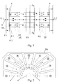
- the partial laminated cores TP are, as is known, arranged with separating and deflecting plates TB spaced from each other, so that between two juxtaposed partial laminated cores TP a radially outwardly closed gap is formed, ie it is formed by radial cooling channels RK, through which the respectively used Cooling medium can flow inward in the direction of rotor laminations 5.
- the outer shape of the stator core 4, ie the sheet metal section can be either square, rectangular or even polygonal. Outside on the stator core 4 solid, material thick, stable press frame 1 are arranged on both sides, which compress the individual stator plates of the stator core 4 and provide the mechanically rigid construction.
- stator core 4 In the stator core 4 are distributed axially over the circumference, in function as inflow and outflow arranged axial cooling channels AK.
- the stator core 4 is held together in a variant of the solution according to the invention by two-sided, one-piece, massive press frame 1 and mechanically stiffened.
- the two pressing frames 1 are bolted to each other with the individual sheets of stator core 4 by means of pressing bolts against each other.
- the stator core 4 is also made in addition welded over its length.
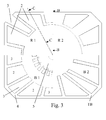
- this one-piece solid pressing frame 1 are provided distributed on a circular disc recesses 2 for cooling air supply. These recesses 2 can be both radially inwardly toward the machine axis 6 out open or axially open, ie then axially straight or obliquely formed continuously.
- deflecting pockets 3 which are distributed on a circular disk in the solid pressing frame 1, are arranged so as to be open radially to the cooling air discharge.
- these can also be arranged for the partial or complete cooling air discharge axially open to the outside and that is when the recesses 2 are arranged open to the cooling air supply radially inwardly toward the machine axis 6 and formed.
- the press frames 1 on both sides consist of at least two individual frames R1 and R2. These are then either bolted together or welded.
- a frame R1 distributed on a circular disk the open recesses 2 for cooling air supply and the open Umlenktaschen 3 arranged for cooling air discharge radially outward, while the other frame 2 closes these recesses 2 and Umlenktaschen 3 and seals.
- the holes for mounting the end shields with the associated machine bearings are introduced to this frame 2. Again, depending on the direction in which the recesses 2 are open, the possibility of partial or complete cooling air discharge axially outward.
- This two-part design of the press frame is particularly advantageous for manufacturing reasons, because the two frames R1 and R2 can be produced with mechanical manufacturing methods easier and faster and thus more cost-effective and after assembly of the two frames R1 and R2 to the press frame still the required high rigidity of the entire Allow construction of the electrical machine.
- separating and deflecting plates TB which act radially inwardly between the partial laminated cores TP are arranged, which provide for the deflection of the cooling air flows to the rotor laminations 5 and also back from the rotor surfaces in these radial cooling ducts RK between the individual partial laminations TP ,
- the partial laminated cores TP are defined by the separating and deflecting plates TB spaced from each other, so that depending on the size of the machine and the thermal load, the partial cooling streams can be divided defined within the rotating electrical machine and their flow direction can be controlled.
- the Umlenktaschen 3 are formed radially fully closed to the machine axis 6, so that no heated, the stator core 4 leaving cooling air can get into the machine interior.
- the recesses 2 for cooling air supply and the deflection pockets 3 for cooling air discharge are optionally designed to be large enough to include one or, if necessary, a plurality of axial cooling channels AK.
- the recesses 2 for cooling air supply and the Umlenktaschen 3 for cooling air discharge are distributed in the press frame 1 is arranged.
- a smooth, simple, continuous intermediate plate ZB is arranged here for separating the two cooling air streams. The stand cooling system is thus practically divided in the middle of the machine. Ideally exactly half in two equal parts.
- the heated cooling medium ie here preferably the warm cooling air very quickly discharged from the interior of the machine in the direction of the two machine ends.
- both the active material of the stator laminated core 4 and also that of the rotor core 5 in which the heat is generated are cooled very intensively.
- the cooling air guide according to the invention allows a very constant temperature distribution over the entire length of the entire rotating electrical machine within the axial cooling channels in a kind of dual countercurrent principle.
- stator cooling system causes a mechanically very rigid stator construction, which makes it possible to use such a housing-less rotating electrical machines for high-dynamic high-speed engine test benches.
- stator cooling system in the solid two-sided solid press frame 1 or in the other variant in a multi-part design of the press frame 1 from at least two frames R1 and R2 only radially inwardly open recesses 2 for cooling air supply.
- the distributed Umlenktaschen 3 for cooling air discharge are in turn also designed to be open only radially outward.
- the Umlenktaschen 3 are formed radially closed to the machine axis 6.
- the other construction of the stator core 4 and the cooling air guide is, as already described above, also identical.
- the axially fed in the middle of the machine cooling air is pressed outwards into the recesses 2.
- the cooling air flow is guided to the rotor surface, cools the Läufererblechumb 5 and flows back radially outward within the channels of the radial cooling channels RK, which open into the axial cooling channels AK, which are designed as discharge channels for the heated cooling air.
- the heated cooling air flow from the individual radial cooling channels collects and is pressed outward in the direction of the machine ends in the Umlenktaschen 3 for cooling air discharge.
- the Umlenktaschen 3 are arranged open to the cooling air discharge radially outward. Ie.
- the now-warm cooling air after having passed through the electric machine, is led away radially outward from the surface of the housing-less rotating electric machine, without being able to flow in the direction of the end shields and the machine bearing.
- press frame 1 can be used in the stator cooling system, in which only one or both frames 1 or 2 of one or both pressing frames 1 of correspondingly shaped two or more identical or different thicker individual sheets are layered.
- the advantage of this embodiment is that this press frame 1 is inexpensive to manufacture in a very simple manner, while in a one-piece Pressrahm 1, this is to produce as a casting or only with complex mechanical processing.
- the stator cooling system can also be designed so that the cross sections of the axial cooling channels AK are arranged symmetrically on a region of an outer radius of the stator core 1 distributed with approximately the same axial cross section.
- a particularly uniform flow guidance of the cooling air can be achieved and, moreover, the noise behavior of this construction is improved.
- This also sets a largely uniform temperature distribution in the interior of the electric machine.
- the recesses 2 for cooling air supply in the press frame 1 are dimensioned and formed so large that they comprise a plurality of adjacent axial cooling channels AK of the stator core 4.
- the deflection pockets 3 for cooling air discharge may comprise fewer or the same number or more axial cooling channels than those which enclose recesses 2.
- a regulation or a very accurate distribution of the cooling air flows over the length of the stator core 4 is possible if the thickness of the arranged between the individual partial plate stacks TP of the stator core 4 separation and deflection plates TB increases from the machine ends towards the machine center in the stator cooling system ,
- the amount of the over the radial cooling channels RK flowing in the spaces between the partial laminated cores TP cooling air flow can be adjusted so that in the middle of the machine, ie where the machine is warmest and even the worst can be cooled, still a sufficient amount of cooling air for cooling available inside the machine ie ultimately arrives at the intermediate plate.
- the separation and deflection plates TB in the spaces between the partial laminated cores TP consist of one or more punched spacer plates or a single wider molded part.
- the thickness of the separating and deflecting plates TB can be set and varied the easiest.
- the stator cooling system Similar to the dimensioning of the recesses 2 and the Umlenktaschen 3, in which these comprise a plurality of axial cooling air ducts, it is also possible in another embodiment of the stator cooling system according to the invention, if the recesses 2 are formed to the cooling air supply in the press frame 1 and the Umlenktaschen 3 in cross-section of different sizes in that the recesses 2, through which the cooling air flows, extend over a different number of plural groove or tooth pitches than the deflecting pockets (3) through which the cooling air flows.
- the cooling air duct in the middle of the machine can be optimized if the intermediate sheet ZB is dimensioned so thick that additional deflection grooves for cooling air reversal are arranged in the axial cooling ducts AK in the intermediate sheet ZB.
- the stator cooling system can also be designed so that the intermediate plate ZB is dimensioned so thick that in the intermediate plate ZB additional radial openings are arranged outward to the machine casing towards the cooling air discharge.
- the additional radial openings in the left and right of the intermediate plate arranged partial laminated core TP, d. H. be arranged in the active sheet material outwards to the machine casing towards the cooling air discharge.
- the stator cooling system according to the invention allows a very intensive cooling of the rotor, although it is a housing-less rotating electrical machine.
- the heated cooling medium can be removed from the machine as quickly as possible and a constant temperature distribution over the entire length of the stator lamination stack arises even at extremely high speeds.
- the result is a mechanically very rigid stator construction with optimum cooling of the two machine bearings.
- FIG. 4 is again for the sake of clarity a radial view through a machine end (section BB and section CC) shown, which illustrates the course of the cooling air flow in the stator core 4 between two partial plate packages TP.
- Down in the FIG. 4 is the cooling air supply through an axial cooling channels AK via a feed channel and the top is the cooling air discharge via an immediately adjacent axial cooling channel which acts as a discharge channel 3 shown.
- stator cooling system in addition to the very intensive cooling of the rotor and its winding and optimum cooling of the two not shown in the figures highly stressed machine bearings, since they are first flows around each of the axially supplied cooling air and cooled.
- a very constant and uniform temperature over the entire machine length forms in active load operation.
- the machine can be made particularly long by this half cooling in this novel construction.
- This stator cooling system according to the invention is applicable to housingless rotary electric three-phase machines with very high speeds and very low moment of inertia of the rotor.
Applications Claiming Priority (2)
| Application Number | Priority Date | Filing Date | Title |
|---|---|---|---|
| DE102008037546 | 2008-11-10 | ||
| DE102009043959A DE102009043959A1 (de) | 2008-11-10 | 2009-09-08 | Ständerkühlsystem für eine gehäuselose rotierende elektrische Maschine |
Publications (3)
| Publication Number | Publication Date |
|---|---|
| EP2230746A2 true EP2230746A2 (fr) | 2010-09-22 |
| EP2230746A3 EP2230746A3 (fr) | 2016-12-21 |
| EP2230746B1 EP2230746B1 (fr) | 2020-09-30 |
Family
ID=42105335
Family Applications (1)
| Application Number | Title | Priority Date | Filing Date |
|---|---|---|---|
| EP09401037.8A Active EP2230746B1 (fr) | 2008-11-10 | 2009-11-10 | Système de refroidissement d`un stator d`une machine électrique tournante sans carcasse |
Country Status (2)
| Country | Link |
|---|---|
| EP (1) | EP2230746B1 (fr) |
| DE (1) | DE102009043959A1 (fr) |
Families Citing this family (1)
| Publication number | Priority date | Publication date | Assignee | Title |
|---|---|---|---|---|
| DE102011053299A1 (de) * | 2011-09-06 | 2013-03-07 | Antriebstechnik Katt Hessen Gmbh | Kühlsystem für eine hochausgenutzte hochtourige rotierende elektrische Synchronmaschine |
Citations (11)
| Publication number | Priority date | Publication date | Assignee | Title |
|---|---|---|---|---|
| US3171996A (en) | 1960-01-07 | 1965-03-02 | Gen Electric | Stator air duct design |
| DE2318090B2 (de) | 1973-04-07 | 1977-06-16 | Licentia Patent-Verwaltungs-Gmbh, 6000 Frankfurt | Kuehlsystem fuer eine gasgekuehlte elektrische maschine |
| EP0118802A1 (fr) | 1983-03-10 | 1984-09-19 | BBC Aktiengesellschaft Brown, Boveri & Cie. | Machine à courant alternatif refroidie par un gaz |
| DE2953800C2 (de) | 1979-08-30 | 1986-02-13 | Šurygin, Sergej Jakovlevič | Elektrische Maschine mit Gaskühlung |
| EP0522210A1 (fr) | 1991-07-12 | 1993-01-13 | Siemens Aktiengesellschaft | Système de refroidissement pour une machine électrique à rotation et machine électrique pour réaliser un tel système |
| DE4320559A1 (de) | 1993-06-21 | 1994-12-22 | Siemens Ag | Elektrische Maschine mit einem innengekühlten Läufer |
| EP0824287A1 (fr) | 1996-08-12 | 1998-02-18 | Siemens Aktiengesellschaft | Machine électrique avec rotor interne refroidi par liquide |
| DE19824202C1 (de) | 1998-05-29 | 1999-09-30 | Siemens Ag | Flüssigkeitsgekühlte elektrische Innenläufermaschine |
| DE10054338C2 (de) | 2000-11-02 | 2003-11-27 | Antriebstechnik Katt Hessen Gm | Kühlsystem für trägheitsarme rotierende elektrische Maschine |
| DE10317593A1 (de) | 2003-04-16 | 2004-11-18 | Siemens Ag | Elektrische Maschine mit gekühlten Ständer- und Läuferblechpaketen und Wicklungen |
| DE102004013133A1 (de) | 2004-03-17 | 2005-10-13 | Siemens Ag | Elektrische Maschine mit verbesserter Kühlung und entsprechendes Kühlverfahren |
Family Cites Families (3)
| Publication number | Priority date | Publication date | Assignee | Title |
|---|---|---|---|---|
| FR626107A (fr) * | 1925-12-10 | 1927-08-30 | Aeg | Dispositif de refroidissement de machines électriques au moyen d'un agent de refroidissement gazeux |
| GB0118565D0 (en) * | 2001-07-31 | 2001-09-19 | Alstom | Electric machine component cooling |
| DE102006049188B3 (de) * | 2006-10-14 | 2008-03-27 | Antriebstechnik Katt Hessen Gmbh | Kühlsystem für hochausgenutzte elektrische Maschinen |
-
2009
- 2009-09-08 DE DE102009043959A patent/DE102009043959A1/de not_active Withdrawn
- 2009-11-10 EP EP09401037.8A patent/EP2230746B1/fr active Active
Patent Citations (11)
| Publication number | Priority date | Publication date | Assignee | Title |
|---|---|---|---|---|
| US3171996A (en) | 1960-01-07 | 1965-03-02 | Gen Electric | Stator air duct design |
| DE2318090B2 (de) | 1973-04-07 | 1977-06-16 | Licentia Patent-Verwaltungs-Gmbh, 6000 Frankfurt | Kuehlsystem fuer eine gasgekuehlte elektrische maschine |
| DE2953800C2 (de) | 1979-08-30 | 1986-02-13 | Šurygin, Sergej Jakovlevič | Elektrische Maschine mit Gaskühlung |
| EP0118802A1 (fr) | 1983-03-10 | 1984-09-19 | BBC Aktiengesellschaft Brown, Boveri & Cie. | Machine à courant alternatif refroidie par un gaz |
| EP0522210A1 (fr) | 1991-07-12 | 1993-01-13 | Siemens Aktiengesellschaft | Système de refroidissement pour une machine électrique à rotation et machine électrique pour réaliser un tel système |
| DE4320559A1 (de) | 1993-06-21 | 1994-12-22 | Siemens Ag | Elektrische Maschine mit einem innengekühlten Läufer |
| EP0824287A1 (fr) | 1996-08-12 | 1998-02-18 | Siemens Aktiengesellschaft | Machine électrique avec rotor interne refroidi par liquide |
| DE19824202C1 (de) | 1998-05-29 | 1999-09-30 | Siemens Ag | Flüssigkeitsgekühlte elektrische Innenläufermaschine |
| DE10054338C2 (de) | 2000-11-02 | 2003-11-27 | Antriebstechnik Katt Hessen Gm | Kühlsystem für trägheitsarme rotierende elektrische Maschine |
| DE10317593A1 (de) | 2003-04-16 | 2004-11-18 | Siemens Ag | Elektrische Maschine mit gekühlten Ständer- und Läuferblechpaketen und Wicklungen |
| DE102004013133A1 (de) | 2004-03-17 | 2005-10-13 | Siemens Ag | Elektrische Maschine mit verbesserter Kühlung und entsprechendes Kühlverfahren |
Also Published As
| Publication number | Publication date |
|---|---|
| EP2230746A3 (fr) | 2016-12-21 |
| EP2230746B1 (fr) | 2020-09-30 |
| DE102009043959A1 (de) | 2010-05-20 |
Similar Documents
| Publication | Publication Date | Title |
|---|---|---|
| DE102008064495B3 (de) | Elektrische Maschine mit mehreren Kühlströmen und Kühlverfahren | |
| EP2368308B1 (fr) | Machine électrique à courant de refroidissement axial et déplacé radialement, et procédé correspondant | |
| EP2568576A2 (fr) | Système de refroidissement pour une machine synchrone électrique rotative ultrarapide à très haute utilisation | |
| EP3433919B1 (fr) | Segment de rotor d'une machine électrique | |
| DE102008022105A1 (de) | Flüssigkeitsgekühlte elektrische Maschine sowie Verfahren zur Kühlung einer solchen elektrischen Maschine | |
| EP2918000B1 (fr) | Machine électrique à refroidissement à air intérieur | |
| EP1248349A2 (fr) | Moteur électrique asynchrone | |
| EP2076956B1 (fr) | Système de refroidissement pour machines électriques tournantes à haut degré d'utilisation | |
| WO2004027960A1 (fr) | Machine electrique comprenant un stator a demi-bobines refroidies | |
| DE112013006949T5 (de) | Elektrische Rotationsmaschine | |
| DE102004013133A1 (de) | Elektrische Maschine mit verbesserter Kühlung und entsprechendes Kühlverfahren | |
| DE2608291A1 (de) | Gasgekuehlter generator-rotor mit erhoehter ventilation | |
| DE102016210930A1 (de) | Rotorblechpaket für eine elektrische Maschine | |
| EP1241772A1 (fr) | Machine électrique rotative refroidie par air | |
| WO2021018343A1 (fr) | Unité d'entraînement électrique, module hybride et ensemble d'entraînement pour véhicule automobile | |
| DE3504782A1 (de) | Laeufer- und/oder staenderblechpaket fuer elektrische maschinen | |
| EP2230746B1 (fr) | Système de refroidissement d`un stator d`une machine électrique tournante sans carcasse | |
| DE102017202801A1 (de) | Rotorblechpaket für einen Rotor | |
| EP1204193B1 (fr) | Système de refroidissement d'une machine électrique tournante à faible inertie | |
| DE102008002299A1 (de) | Rotor mit innengekühlter Rotorwicklung | |
| EP0120279B1 (fr) | Machine à courant alternatif | |
| EP0889572A2 (fr) | Machine Eléctrique | |
| WO2021209086A1 (fr) | Rotor de machine électrique tournante et machine électrique tournante | |
| DE102009048265A1 (de) | Schleifringanordnung für eine rotierende elektrische Maschine | |
| DE4337463C2 (de) | Ständer mit Belüftungseinrichtung für gehäuselose elektrische Maschine |
Legal Events
| Date | Code | Title | Description |
|---|---|---|---|
| PUAI | Public reference made under article 153(3) epc to a published international application that has entered the european phase |
Free format text: ORIGINAL CODE: 0009012 |
|
| AK | Designated contracting states |
Kind code of ref document: A2 Designated state(s): AT BE BG CH CY CZ DE DK EE ES FI FR GB GR HR HU IE IS IT LI LT LU LV MC MK MT NL NO PL PT RO SE SI SK SM TR |
|
| AX | Request for extension of the european patent |
Extension state: AL BA RS |
|
| PUAL | Search report despatched |
Free format text: ORIGINAL CODE: 0009013 |
|
| AK | Designated contracting states |
Kind code of ref document: A3 Designated state(s): AT BE BG CH CY CZ DE DK EE ES FI FR GB GR HR HU IE IS IT LI LT LU LV MC MK MT NL NO PL PT RO SE SI SK SM TR |
|
| AX | Request for extension of the european patent |
Extension state: AL BA RS |
|
| RIC1 | Information provided on ipc code assigned before grant |
Ipc: H02K 9/04 20060101ALN20161117BHEP Ipc: H02K 1/20 20060101AFI20161117BHEP Ipc: H02K 1/32 20060101ALN20161117BHEP |
|
| STAA | Information on the status of an ep patent application or granted ep patent |
Free format text: STATUS: REQUEST FOR EXAMINATION WAS MADE |
|
| 17P | Request for examination filed |
Effective date: 20170426 |
|
| STAA | Information on the status of an ep patent application or granted ep patent |
Free format text: STATUS: EXAMINATION IS IN PROGRESS |
|
| 17Q | First examination report despatched |
Effective date: 20180918 |
|
| GRAP | Despatch of communication of intention to grant a patent |
Free format text: ORIGINAL CODE: EPIDOSNIGR1 |
|
| STAA | Information on the status of an ep patent application or granted ep patent |
Free format text: STATUS: GRANT OF PATENT IS INTENDED |
|
| RIC1 | Information provided on ipc code assigned before grant |
Ipc: H02K 9/04 20060101ALN20200122BHEP Ipc: H02K 1/20 20060101AFI20200122BHEP Ipc: H02K 1/32 20060101ALN20200122BHEP |
|
| INTG | Intention to grant announced |
Effective date: 20200217 |
|
| GRAJ | Information related to disapproval of communication of intention to grant by the applicant or resumption of examination proceedings by the epo deleted |
Free format text: ORIGINAL CODE: EPIDOSDIGR1 |
|
| STAA | Information on the status of an ep patent application or granted ep patent |
Free format text: STATUS: EXAMINATION IS IN PROGRESS |
|
| INTC | Intention to grant announced (deleted) | ||
| GRAS | Grant fee paid |
Free format text: ORIGINAL CODE: EPIDOSNIGR3 |
|
| STAA | Information on the status of an ep patent application or granted ep patent |
Free format text: STATUS: GRANT OF PATENT IS INTENDED |
|
| GRAP | Despatch of communication of intention to grant a patent |
Free format text: ORIGINAL CODE: EPIDOSNIGR1 |
|
| RIC1 | Information provided on ipc code assigned before grant |
Ipc: H02K 9/04 20060101ALN20200709BHEP Ipc: H02K 1/20 20060101AFI20200709BHEP Ipc: H02K 1/32 20060101ALN20200709BHEP |
|
| INTG | Intention to grant announced |
Effective date: 20200724 |
|
| GRAA | (expected) grant |
Free format text: ORIGINAL CODE: 0009210 |
|
| STAA | Information on the status of an ep patent application or granted ep patent |
Free format text: STATUS: THE PATENT HAS BEEN GRANTED |
|
| AK | Designated contracting states |
Kind code of ref document: B1 Designated state(s): AT BE BG CH CY CZ DE DK EE ES FI FR GB GR HR HU IE IS IT LI LT LU LV MC MK MT NL NO PL PT RO SE SI SK SM TR |
|
| REG | Reference to a national code |
Ref country code: CH Ref legal event code: EP Ref country code: GB Ref legal event code: FG4D Free format text: NOT ENGLISH |
|
| REG | Reference to a national code |
Ref country code: DE Ref legal event code: R096 Ref document number: 502009016279 Country of ref document: DE Ref country code: AT Ref legal event code: REF Ref document number: 1319801 Country of ref document: AT Kind code of ref document: T Effective date: 20201015 |
|
| REG | Reference to a national code |
Ref country code: IE Ref legal event code: FG4D Free format text: LANGUAGE OF EP DOCUMENT: GERMAN |
|
| PG25 | Lapsed in a contracting state [announced via postgrant information from national office to epo] |
Ref country code: GR Free format text: LAPSE BECAUSE OF FAILURE TO SUBMIT A TRANSLATION OF THE DESCRIPTION OR TO PAY THE FEE WITHIN THE PRESCRIBED TIME-LIMIT Effective date: 20201231 Ref country code: NO Free format text: LAPSE BECAUSE OF FAILURE TO SUBMIT A TRANSLATION OF THE DESCRIPTION OR TO PAY THE FEE WITHIN THE PRESCRIBED TIME-LIMIT Effective date: 20201230 Ref country code: HR Free format text: LAPSE BECAUSE OF FAILURE TO SUBMIT A TRANSLATION OF THE DESCRIPTION OR TO PAY THE FEE WITHIN THE PRESCRIBED TIME-LIMIT Effective date: 20200930 Ref country code: SE Free format text: LAPSE BECAUSE OF FAILURE TO SUBMIT A TRANSLATION OF THE DESCRIPTION OR TO PAY THE FEE WITHIN THE PRESCRIBED TIME-LIMIT Effective date: 20200930 Ref country code: FI Free format text: LAPSE BECAUSE OF FAILURE TO SUBMIT A TRANSLATION OF THE DESCRIPTION OR TO PAY THE FEE WITHIN THE PRESCRIBED TIME-LIMIT Effective date: 20200930 Ref country code: BG Free format text: LAPSE BECAUSE OF FAILURE TO SUBMIT A TRANSLATION OF THE DESCRIPTION OR TO PAY THE FEE WITHIN THE PRESCRIBED TIME-LIMIT Effective date: 20201230 |
|
| PG25 | Lapsed in a contracting state [announced via postgrant information from national office to epo] |
Ref country code: LV Free format text: LAPSE BECAUSE OF FAILURE TO SUBMIT A TRANSLATION OF THE DESCRIPTION OR TO PAY THE FEE WITHIN THE PRESCRIBED TIME-LIMIT Effective date: 20200930 |
|
| REG | Reference to a national code |
Ref country code: NL Ref legal event code: MP Effective date: 20200930 |
|
| REG | Reference to a national code |
Ref country code: LT Ref legal event code: MG4D |
|
| PG25 | Lapsed in a contracting state [announced via postgrant information from national office to epo] |
Ref country code: EE Free format text: LAPSE BECAUSE OF FAILURE TO SUBMIT A TRANSLATION OF THE DESCRIPTION OR TO PAY THE FEE WITHIN THE PRESCRIBED TIME-LIMIT Effective date: 20200930 Ref country code: RO Free format text: LAPSE BECAUSE OF FAILURE TO SUBMIT A TRANSLATION OF THE DESCRIPTION OR TO PAY THE FEE WITHIN THE PRESCRIBED TIME-LIMIT Effective date: 20200930 Ref country code: SM Free format text: LAPSE BECAUSE OF FAILURE TO SUBMIT A TRANSLATION OF THE DESCRIPTION OR TO PAY THE FEE WITHIN THE PRESCRIBED TIME-LIMIT Effective date: 20200930 Ref country code: LT Free format text: LAPSE BECAUSE OF FAILURE TO SUBMIT A TRANSLATION OF THE DESCRIPTION OR TO PAY THE FEE WITHIN THE PRESCRIBED TIME-LIMIT Effective date: 20200930 Ref country code: NL Free format text: LAPSE BECAUSE OF FAILURE TO SUBMIT A TRANSLATION OF THE DESCRIPTION OR TO PAY THE FEE WITHIN THE PRESCRIBED TIME-LIMIT Effective date: 20200930 Ref country code: PT Free format text: LAPSE BECAUSE OF FAILURE TO SUBMIT A TRANSLATION OF THE DESCRIPTION OR TO PAY THE FEE WITHIN THE PRESCRIBED TIME-LIMIT Effective date: 20210201 |
|
| PGFP | Annual fee paid to national office [announced via postgrant information from national office to epo] |
Ref country code: IT Payment date: 20210111 Year of fee payment: 12 |
|
| PG25 | Lapsed in a contracting state [announced via postgrant information from national office to epo] |
Ref country code: ES Free format text: LAPSE BECAUSE OF FAILURE TO SUBMIT A TRANSLATION OF THE DESCRIPTION OR TO PAY THE FEE WITHIN THE PRESCRIBED TIME-LIMIT Effective date: 20200930 Ref country code: IS Free format text: LAPSE BECAUSE OF FAILURE TO SUBMIT A TRANSLATION OF THE DESCRIPTION OR TO PAY THE FEE WITHIN THE PRESCRIBED TIME-LIMIT Effective date: 20210130 Ref country code: PL Free format text: LAPSE BECAUSE OF FAILURE TO SUBMIT A TRANSLATION OF THE DESCRIPTION OR TO PAY THE FEE WITHIN THE PRESCRIBED TIME-LIMIT Effective date: 20200930 |
|
| PG25 | Lapsed in a contracting state [announced via postgrant information from national office to epo] |
Ref country code: SK Free format text: LAPSE BECAUSE OF FAILURE TO SUBMIT A TRANSLATION OF THE DESCRIPTION OR TO PAY THE FEE WITHIN THE PRESCRIBED TIME-LIMIT Effective date: 20200930 Ref country code: MC Free format text: LAPSE BECAUSE OF FAILURE TO SUBMIT A TRANSLATION OF THE DESCRIPTION OR TO PAY THE FEE WITHIN THE PRESCRIBED TIME-LIMIT Effective date: 20200930 |
|
| REG | Reference to a national code |
Ref country code: CH Ref legal event code: PL |
|
| REG | Reference to a national code |
Ref country code: DE Ref legal event code: R097 Ref document number: 502009016279 Country of ref document: DE |
|
| PG25 | Lapsed in a contracting state [announced via postgrant information from national office to epo] |
Ref country code: LU Free format text: LAPSE BECAUSE OF NON-PAYMENT OF DUE FEES Effective date: 20201110 |
|
| PLBE | No opposition filed within time limit |
Free format text: ORIGINAL CODE: 0009261 |
|
| STAA | Information on the status of an ep patent application or granted ep patent |
Free format text: STATUS: NO OPPOSITION FILED WITHIN TIME LIMIT |
|
| REG | Reference to a national code |
Ref country code: BE Ref legal event code: MM Effective date: 20201130 |
|
| GBPC | Gb: european patent ceased through non-payment of renewal fee |
Effective date: 20201230 |
|
| PG25 | Lapsed in a contracting state [announced via postgrant information from national office to epo] |
Ref country code: CH Free format text: LAPSE BECAUSE OF NON-PAYMENT OF DUE FEES Effective date: 20201130 Ref country code: DK Free format text: LAPSE BECAUSE OF FAILURE TO SUBMIT A TRANSLATION OF THE DESCRIPTION OR TO PAY THE FEE WITHIN THE PRESCRIBED TIME-LIMIT Effective date: 20200930 Ref country code: LI Free format text: LAPSE BECAUSE OF NON-PAYMENT OF DUE FEES Effective date: 20201130 |
|
| 26N | No opposition filed |
Effective date: 20210701 |
|
| PG25 | Lapsed in a contracting state [announced via postgrant information from national office to epo] |
Ref country code: IE Free format text: LAPSE BECAUSE OF NON-PAYMENT OF DUE FEES Effective date: 20201110 Ref country code: FR Free format text: LAPSE BECAUSE OF NON-PAYMENT OF DUE FEES Effective date: 20201130 |
|
| PG25 | Lapsed in a contracting state [announced via postgrant information from national office to epo] |
Ref country code: SI Free format text: LAPSE BECAUSE OF FAILURE TO SUBMIT A TRANSLATION OF THE DESCRIPTION OR TO PAY THE FEE WITHIN THE PRESCRIBED TIME-LIMIT Effective date: 20200930 Ref country code: GB Free format text: LAPSE BECAUSE OF NON-PAYMENT OF DUE FEES Effective date: 20201230 |
|
| PG25 | Lapsed in a contracting state [announced via postgrant information from national office to epo] |
Ref country code: IS Free format text: LAPSE BECAUSE OF FAILURE TO SUBMIT A TRANSLATION OF THE DESCRIPTION OR TO PAY THE FEE WITHIN THE PRESCRIBED TIME-LIMIT Effective date: 20210130 Ref country code: TR Free format text: LAPSE BECAUSE OF FAILURE TO SUBMIT A TRANSLATION OF THE DESCRIPTION OR TO PAY THE FEE WITHIN THE PRESCRIBED TIME-LIMIT Effective date: 20200930 Ref country code: MT Free format text: LAPSE BECAUSE OF FAILURE TO SUBMIT A TRANSLATION OF THE DESCRIPTION OR TO PAY THE FEE WITHIN THE PRESCRIBED TIME-LIMIT Effective date: 20200930 Ref country code: CY Free format text: LAPSE BECAUSE OF FAILURE TO SUBMIT A TRANSLATION OF THE DESCRIPTION OR TO PAY THE FEE WITHIN THE PRESCRIBED TIME-LIMIT Effective date: 20200930 |
|
| PG25 | Lapsed in a contracting state [announced via postgrant information from national office to epo] |
Ref country code: MK Free format text: LAPSE BECAUSE OF FAILURE TO SUBMIT A TRANSLATION OF THE DESCRIPTION OR TO PAY THE FEE WITHIN THE PRESCRIBED TIME-LIMIT Effective date: 20200930 |
|
| PG25 | Lapsed in a contracting state [announced via postgrant information from national office to epo] |
Ref country code: BE Free format text: LAPSE BECAUSE OF NON-PAYMENT OF DUE FEES Effective date: 20201130 |
|
| PG25 | Lapsed in a contracting state [announced via postgrant information from national office to epo] |
Ref country code: IT Free format text: LAPSE BECAUSE OF NON-PAYMENT OF DUE FEES Effective date: 20211110 |
|
| PGFP | Annual fee paid to national office [announced via postgrant information from national office to epo] |
Ref country code: DE Payment date: 20230127 Year of fee payment: 14 |
|
| PGFP | Annual fee paid to national office [announced via postgrant information from national office to epo] |
Ref country code: CZ Payment date: 20231108 Year of fee payment: 15 Ref country code: AT Payment date: 20231106 Year of fee payment: 15 |