EP2230746A2 - Stator cooling system for a rotating electric machine without a housing - Google Patents
Stator cooling system for a rotating electric machine without a housing Download PDFInfo
- Publication number
- EP2230746A2 EP2230746A2 EP09401037A EP09401037A EP2230746A2 EP 2230746 A2 EP2230746 A2 EP 2230746A2 EP 09401037 A EP09401037 A EP 09401037A EP 09401037 A EP09401037 A EP 09401037A EP 2230746 A2 EP2230746 A2 EP 2230746A2
- Authority
- EP
- European Patent Office
- Prior art keywords
- cooling air
- cooling
- axial
- recesses
- umlenktaschen
- Prior art date
- Legal status (The legal status is an assumption and is not a legal conclusion. Google has not performed a legal analysis and makes no representation as to the accuracy of the status listed.)
- Granted
Links
- 238000001816 cooling Methods 0.000 title claims abstract description 242
- 238000003825 pressing Methods 0.000 claims abstract description 10
- 238000003475 lamination Methods 0.000 claims description 16
- 239000007787 solid Substances 0.000 claims description 12
- 125000006850 spacer group Chemical group 0.000 claims description 5
- 239000000463 material Substances 0.000 claims description 4
- 239000011295 pitch Substances 0.000 claims description 2
- 239000007769 metal material Substances 0.000 claims 1
- 238000010276 construction Methods 0.000 description 10
- 238000004804 winding Methods 0.000 description 10
- 239000002826 coolant Substances 0.000 description 8
- 238000009826 distribution Methods 0.000 description 7
- 239000007788 liquid Substances 0.000 description 5
- 239000002184 metal Substances 0.000 description 5
- 230000000694 effects Effects 0.000 description 3
- 238000004519 manufacturing process Methods 0.000 description 3
- 238000000926 separation method Methods 0.000 description 3
- 239000011149 active material Substances 0.000 description 2
- 230000015572 biosynthetic process Effects 0.000 description 1
- 238000005266 casting Methods 0.000 description 1
- 230000001419 dependent effect Effects 0.000 description 1
- 230000009977 dual effect Effects 0.000 description 1
- 238000009434 installation Methods 0.000 description 1
- 238000009413 insulation Methods 0.000 description 1
- 239000003507 refrigerant Substances 0.000 description 1
- 238000007789 sealing Methods 0.000 description 1
- 238000003860 storage Methods 0.000 description 1
- 238000010792 warming Methods 0.000 description 1
Images

Classifications
-
- H—ELECTRICITY
- H02—GENERATION; CONVERSION OR DISTRIBUTION OF ELECTRIC POWER
- H02K—DYNAMO-ELECTRIC MACHINES
- H02K1/00—Details of the magnetic circuit
- H02K1/06—Details of the magnetic circuit characterised by the shape, form or construction
- H02K1/12—Stationary parts of the magnetic circuit
- H02K1/20—Stationary parts of the magnetic circuit with channels or ducts for flow of cooling medium
-
- H—ELECTRICITY
- H02—GENERATION; CONVERSION OR DISTRIBUTION OF ELECTRIC POWER
- H02K—DYNAMO-ELECTRIC MACHINES
- H02K1/00—Details of the magnetic circuit
- H02K1/06—Details of the magnetic circuit characterised by the shape, form or construction
- H02K1/22—Rotating parts of the magnetic circuit
- H02K1/32—Rotating parts of the magnetic circuit with channels or ducts for flow of cooling medium
-
- H—ELECTRICITY
- H02—GENERATION; CONVERSION OR DISTRIBUTION OF ELECTRIC POWER
- H02K—DYNAMO-ELECTRIC MACHINES
- H02K9/00—Arrangements for cooling or ventilating
- H02K9/02—Arrangements for cooling or ventilating by ambient air flowing through the machine
- H02K9/04—Arrangements for cooling or ventilating by ambient air flowing through the machine having means for generating a flow of cooling medium
Definitions
- the invention relates to a stator cooling system for a housing-less rotating electric machine, with draft cooling with a stator and Läufererblechong consisting of partial laminated cores, the partial laminated cores with Leit respondeds- and spacer segments are spaced from each other and the stator core is provided with solid pressing frame, wherein distributed axially over the circumference Inlet and outlet channels are formed as axial cooling channels are arranged on both sides with external fans, especially for three-phase machines.
- An intensive cooling system for low-inertia rotating electrical machines especially for three-phase machines with external or internal cooling is in the DE 100 54 338 C2 demonstrated. It is both the rotor and the square stator core each composed of several partial laminated cores. On the outer contour of a square stator lamination package close to the outside over the entire length axially on one side closed inlet and outlet chambers distributed over the circumference with approximately the same axial cross-section. From an inflow chamber lead radial cooling passages through the stator core, which are axially bounded by the end plates of the stator sub-laminations axially and Leit Vintages- and spacer segments in the back region of the stator core.
- the winding with the slot insulation represents the radial boundary.
- the cooling air can flow to the rotor surface and into the rotor.
- the cooling air is additionally swirled by the rotation of the rotor, so that an intensive cooling is achieved.
- the heated air is forced into the radially outflowing running cooling channels of the stator core.
- These cooling channels are formed in the same manner as the cooling channels through which the air flows, and are connected to the outflow chambers. This air cools the stator core pretty intense.
- the cooling air is thereby deflected and flows through openings in the press frame of the square stator core in the winding head space and cools, among other things, even the winding heads of this rotating electric machine.
- this technical solution involves a relatively expensive sheet metal section.
- the magnetically non-active but thermally sensitive structural parts, in particular, the machine bearings are additionally heated.
- a structure of an electric machine, where both the stator and the rotor laminations can be cooled intensively, is in the DE 103 17 593 A1 described.
- This machine consists of an embodiment of centrally divided stator and rotor laminations and centric axial air discharge.
- the runner can not be formed particularly low in inertia and highly exploitable, since it is equipped with axially continuous cooling channels, which unnecessarily weakens the electromagnetically active rotor cross-section.
- the invention has for its object to provide an intense stator cooling system for a housing-less rotating electrical machine, especially for a three-phase machine with external cooling, which dissipates the heated cooling medium as quickly as possible from the machine, a constant temperature distribution over the entire length of the stator core itself ensures extremely high speeds, the magnetically non-active, but thermally sensitive construction parts, in particular the two machine bearings should not be heated in addition and defies housing-less design a mechanically very rigid stator construction is achieved.
- Claim 1 describes the general inventive solution for a stator cooling system for a caseless rotary electric machine. This version is for foreign cooling as draft cooling, namely for three-phase machines with extremely high speeds with a stator and Läufererblechpers consisting of partial laminated cores TP feasible.
- a separate cooling here two blowers G1 and G2 are arranged, which provide the cooling medium, here preferably cooling air, as purely axial cooling air supply respectively on both sides of the machine.
- the blowers G1 and G2 can be arranged laterally or above the machine.
- the partial laminated cores TP are, as is known, arranged with separating and deflecting plates TB spaced from each other, so that between two juxtaposed partial laminated cores TP a radially outwardly closed gap is formed, ie it is formed by radial cooling channels RK, through which the respectively used Cooling medium can flow inward in the direction of rotor laminations 5.
- the outer shape of the stator core 4, ie the sheet metal section can be either square, rectangular or even polygonal. Outside on the stator core 4 solid, material thick, stable press frame 1 are arranged on both sides, which compress the individual stator plates of the stator core 4 and provide the mechanically rigid construction.
- stator core 4 In the stator core 4 are distributed axially over the circumference, in function as inflow and outflow arranged axial cooling channels AK.
- the stator core 4 is held together in a variant of the solution according to the invention by two-sided, one-piece, massive press frame 1 and mechanically stiffened.
- the two pressing frames 1 are bolted to each other with the individual sheets of stator core 4 by means of pressing bolts against each other.
- the stator core 4 is also made in addition welded over its length.
- this one-piece solid pressing frame 1 are provided distributed on a circular disc recesses 2 for cooling air supply. These recesses 2 can be both radially inwardly toward the machine axis 6 out open or axially open, ie then axially straight or obliquely formed continuously.
- deflecting pockets 3 which are distributed on a circular disk in the solid pressing frame 1, are arranged so as to be open radially to the cooling air discharge.
- these can also be arranged for the partial or complete cooling air discharge axially open to the outside and that is when the recesses 2 are arranged open to the cooling air supply radially inwardly toward the machine axis 6 and formed.
- the press frames 1 on both sides consist of at least two individual frames R1 and R2. These are then either bolted together or welded.
- a frame R1 distributed on a circular disk the open recesses 2 for cooling air supply and the open Umlenktaschen 3 arranged for cooling air discharge radially outward, while the other frame 2 closes these recesses 2 and Umlenktaschen 3 and seals.
- the holes for mounting the end shields with the associated machine bearings are introduced to this frame 2. Again, depending on the direction in which the recesses 2 are open, the possibility of partial or complete cooling air discharge axially outward.
- This two-part design of the press frame is particularly advantageous for manufacturing reasons, because the two frames R1 and R2 can be produced with mechanical manufacturing methods easier and faster and thus more cost-effective and after assembly of the two frames R1 and R2 to the press frame still the required high rigidity of the entire Allow construction of the electrical machine.
- separating and deflecting plates TB which act radially inwardly between the partial laminated cores TP are arranged, which provide for the deflection of the cooling air flows to the rotor laminations 5 and also back from the rotor surfaces in these radial cooling ducts RK between the individual partial laminations TP ,
- the partial laminated cores TP are defined by the separating and deflecting plates TB spaced from each other, so that depending on the size of the machine and the thermal load, the partial cooling streams can be divided defined within the rotating electrical machine and their flow direction can be controlled.
- the Umlenktaschen 3 are formed radially fully closed to the machine axis 6, so that no heated, the stator core 4 leaving cooling air can get into the machine interior.
- the recesses 2 for cooling air supply and the deflection pockets 3 for cooling air discharge are optionally designed to be large enough to include one or, if necessary, a plurality of axial cooling channels AK.
- the recesses 2 for cooling air supply and the Umlenktaschen 3 for cooling air discharge are distributed in the press frame 1 is arranged.
- a smooth, simple, continuous intermediate plate ZB is arranged here for separating the two cooling air streams. The stand cooling system is thus practically divided in the middle of the machine. Ideally exactly half in two equal parts.
- the heated cooling medium ie here preferably the warm cooling air very quickly discharged from the interior of the machine in the direction of the two machine ends.
- both the active material of the stator laminated core 4 and also that of the rotor core 5 in which the heat is generated are cooled very intensively.
- the cooling air guide according to the invention allows a very constant temperature distribution over the entire length of the entire rotating electrical machine within the axial cooling channels in a kind of dual countercurrent principle.
- stator cooling system causes a mechanically very rigid stator construction, which makes it possible to use such a housing-less rotating electrical machines for high-dynamic high-speed engine test benches.
- stator cooling system in the solid two-sided solid press frame 1 or in the other variant in a multi-part design of the press frame 1 from at least two frames R1 and R2 only radially inwardly open recesses 2 for cooling air supply.
- the distributed Umlenktaschen 3 for cooling air discharge are in turn also designed to be open only radially outward.
- the Umlenktaschen 3 are formed radially closed to the machine axis 6.
- the other construction of the stator core 4 and the cooling air guide is, as already described above, also identical.
- the axially fed in the middle of the machine cooling air is pressed outwards into the recesses 2.
- the cooling air flow is guided to the rotor surface, cools the Läufererblechumb 5 and flows back radially outward within the channels of the radial cooling channels RK, which open into the axial cooling channels AK, which are designed as discharge channels for the heated cooling air.
- the heated cooling air flow from the individual radial cooling channels collects and is pressed outward in the direction of the machine ends in the Umlenktaschen 3 for cooling air discharge.
- the Umlenktaschen 3 are arranged open to the cooling air discharge radially outward. Ie.
- the now-warm cooling air after having passed through the electric machine, is led away radially outward from the surface of the housing-less rotating electric machine, without being able to flow in the direction of the end shields and the machine bearing.
- press frame 1 can be used in the stator cooling system, in which only one or both frames 1 or 2 of one or both pressing frames 1 of correspondingly shaped two or more identical or different thicker individual sheets are layered.
- the advantage of this embodiment is that this press frame 1 is inexpensive to manufacture in a very simple manner, while in a one-piece Pressrahm 1, this is to produce as a casting or only with complex mechanical processing.
- the stator cooling system can also be designed so that the cross sections of the axial cooling channels AK are arranged symmetrically on a region of an outer radius of the stator core 1 distributed with approximately the same axial cross section.
- a particularly uniform flow guidance of the cooling air can be achieved and, moreover, the noise behavior of this construction is improved.
- This also sets a largely uniform temperature distribution in the interior of the electric machine.
- the recesses 2 for cooling air supply in the press frame 1 are dimensioned and formed so large that they comprise a plurality of adjacent axial cooling channels AK of the stator core 4.
- the deflection pockets 3 for cooling air discharge may comprise fewer or the same number or more axial cooling channels than those which enclose recesses 2.
- a regulation or a very accurate distribution of the cooling air flows over the length of the stator core 4 is possible if the thickness of the arranged between the individual partial plate stacks TP of the stator core 4 separation and deflection plates TB increases from the machine ends towards the machine center in the stator cooling system ,
- the amount of the over the radial cooling channels RK flowing in the spaces between the partial laminated cores TP cooling air flow can be adjusted so that in the middle of the machine, ie where the machine is warmest and even the worst can be cooled, still a sufficient amount of cooling air for cooling available inside the machine ie ultimately arrives at the intermediate plate.
- the separation and deflection plates TB in the spaces between the partial laminated cores TP consist of one or more punched spacer plates or a single wider molded part.
- the thickness of the separating and deflecting plates TB can be set and varied the easiest.
- the stator cooling system Similar to the dimensioning of the recesses 2 and the Umlenktaschen 3, in which these comprise a plurality of axial cooling air ducts, it is also possible in another embodiment of the stator cooling system according to the invention, if the recesses 2 are formed to the cooling air supply in the press frame 1 and the Umlenktaschen 3 in cross-section of different sizes in that the recesses 2, through which the cooling air flows, extend over a different number of plural groove or tooth pitches than the deflecting pockets (3) through which the cooling air flows.
- the cooling air duct in the middle of the machine can be optimized if the intermediate sheet ZB is dimensioned so thick that additional deflection grooves for cooling air reversal are arranged in the axial cooling ducts AK in the intermediate sheet ZB.
- the stator cooling system can also be designed so that the intermediate plate ZB is dimensioned so thick that in the intermediate plate ZB additional radial openings are arranged outward to the machine casing towards the cooling air discharge.
- the additional radial openings in the left and right of the intermediate plate arranged partial laminated core TP, d. H. be arranged in the active sheet material outwards to the machine casing towards the cooling air discharge.
- the stator cooling system according to the invention allows a very intensive cooling of the rotor, although it is a housing-less rotating electrical machine.
- the heated cooling medium can be removed from the machine as quickly as possible and a constant temperature distribution over the entire length of the stator lamination stack arises even at extremely high speeds.
- the result is a mechanically very rigid stator construction with optimum cooling of the two machine bearings.
- FIG. 4 is again for the sake of clarity a radial view through a machine end (section BB and section CC) shown, which illustrates the course of the cooling air flow in the stator core 4 between two partial plate packages TP.
- Down in the FIG. 4 is the cooling air supply through an axial cooling channels AK via a feed channel and the top is the cooling air discharge via an immediately adjacent axial cooling channel which acts as a discharge channel 3 shown.
- stator cooling system in addition to the very intensive cooling of the rotor and its winding and optimum cooling of the two not shown in the figures highly stressed machine bearings, since they are first flows around each of the axially supplied cooling air and cooled.
- a very constant and uniform temperature over the entire machine length forms in active load operation.
- the machine can be made particularly long by this half cooling in this novel construction.
- This stator cooling system according to the invention is applicable to housingless rotary electric three-phase machines with very high speeds and very low moment of inertia of the rotor.
Landscapes
- Engineering & Computer Science (AREA)
- Power Engineering (AREA)
- Iron Core Of Rotating Electric Machines (AREA)
Abstract
Description
Die Erfindung betrifft ein Ständerkühlsystem für eine gehäuselose rotierende elektrische Maschine, mit Durchzugskühlung mit einem Ständer- und Läuferblechpaket bestehend aus Teilblechpaketen, wobei die Teilblechpakete mit Leiteinrichtungs- und Abstandshaltersegmenten voneinander beabstandet sind und das Ständerblechpaket mit massiven Pressrahmen versehen ist, wobei axial über den Umfang verteilt Zu- und Abströmkanäle als axiale Kühlkanäle ausgebildet sind mit beidseitig angeordneten Fremdlüftern, insbesondere für Drehstrommaschinen.The invention relates to a stator cooling system for a housing-less rotating electric machine, with draft cooling with a stator and Läufererblechpaket consisting of partial laminated cores, the partial laminated cores with Leiteinrichtungs- and spacer segments are spaced from each other and the stator core is provided with solid pressing frame, wherein distributed axially over the circumference Inlet and outlet channels are formed as axial cooling channels are arranged on both sides with external fans, especially for three-phase machines.
Für bestimmte spezielle Anwendungsfälle, wie z. B. für Motorenprüfstände werden sehr hochdynamische Antriebe benötigt. Solcherart hochdynamische rotierende elektrische Maschinen sind elektrisch hochausgenutzte Elektromotoren, die auf Grund der realisierten hohen Leistungsdichte sich besonders schnell und intensiv erwärmen können. Hochausgenutzte rotierende elektrische Maschinen erfordern zudem eine Läuferkonstruktion mit möglichst geringem Durchmesser, die sich deshalb nur bedingt gut kühlen lässt. Deshalb ist es besonders wichtig, dass die aus dem Ständer stammende Wärme nicht noch zur Erwärmung des Läufers beiträgt. Die Realisierung einer solchen Maschinenausführung bedingt neben einer intensiven Kühlung des Läuferblechpaketes deshalb auch eine besonders optimale Kühlung des Ständerblechpaketes.For certain special applications, such. B. for engine test benches very high dynamic drives are needed. Such highly dynamic rotating electrical machines are electrically highly utilized electric motors that can heat up very quickly and intensively due to the high power density realized. Highly used rotating electrical machines also require a rotor design with the smallest possible diameter, which therefore can only cool to a limited extent. Therefore, it is particularly important that the heat from the stand does not contribute to the warming of the runner. The realization of such a machine design therefore requires not only an intensive cooling of the rotor core package but also a particularly optimal cooling of the stator core.
Es ist allgemein bekannt, dass eine intensive Luftkühlung des Läufer- und des Ständerblechpaketes mit Hilfe von axialen Kühlkanälen oder auch mit axialen und radialen Kühlkanälen erreicht werden kann. Dabei sind die Ständer- und Läuferblechpakete in der Regel aus mehreren Teilblechpaketen aufgebaut. Luftgekühlte Ausführungen sind in der
Eine weitere mögliche Lösung für eine intensive Kühlung einer hochausgenutzten rotierenden elektrischen Maschine besteht in der Anwendung der Flüssigkeitskühlung, z. B entsprechend
In einer anderen Schrift, der
In der
Ein intensives Kühlsystem für trägheitsarme rotierende elektrische Maschinen insbesondere für Drehstrommaschinen mit Fremd- oder Eigenkühlung ist in der
In der
Aus der
Ein Aufbau einer elektrischen Maschine, wo sowohl das Ständer- als auch das Läuferblechpaket intensiv gekühlt werden kann, ist in der
Eine andere technische Lösung, in der sich auf dem Umfang eines Ständerblechpaketes im Gehäuse einer rotierenden elektrischen Maschine verteilt Abschnitte für die Zufuhr und Abfuhr des Kühlgases einander abwechseln, ist in der
Der Erfindung liegt die Aufgabe zugrunde, ein intensives Ständerkühlsystem für eine gehäuselose rotierende elektrische Maschine, insbesondere für eine Drehstrommaschine mit Fremdkühlung zu schaffen, das das erwärmte Kühlmedium so schnell als möglich aus der Maschine abführt, eine konstante Temperaturverteilung über die gesamte Länge des Ständerblechpakets selbst bei extrem hohen Drehzahlen gewährleistet, wobei die magnetisch nicht aktiven, aber thermisch empfindlichen Konstruktionsteile, wie insbesondere die beiden Maschinenlager nicht zusätzlich erwärmt werden sollen und trotzt gehäuseloser Ausführung eine mechanisch sehr steife Ständerkonstruktion erreicht wird.The invention has for its object to provide an intense stator cooling system for a housing-less rotating electrical machine, especially for a three-phase machine with external cooling, which dissipates the heated cooling medium as quickly as possible from the machine, a constant temperature distribution over the entire length of the stator core itself ensures extremely high speeds, the magnetically non-active, but thermally sensitive construction parts, in particular the two machine bearings should not be heated in addition and defies housing-less design a mechanically very rigid stator construction is achieved.
Die Aufgabe der Erfindung wird durch die Merkmale des 1. Patentanspruchs gelöst. Weitere zweckmäßige Ausgestaltungen der Erfindung sind Gegenstand der rückbezüglichen Unteransprüche. Anspruch 1 beschreibt die allgemeine erfinderische Lösung für ein Ständerkühlsystem für eine gehäuselose rotierende elektrische Maschine. Diese Ausführung ist für Fremdkühlung als Durchzugskühlung, nämlich für Drehstrommaschinen mit extrem hohen Drehzahlen mit einem Ständer- und Läuferblechpaket bestehend aus Teilblechpaketen TP realisierbar. Als Fremdkühlung sind hierbei zwei Gebläse G1 und G2 angeordnet, die das Kühlmedium, hier vorzugsweise Kühlluft, als rein axiale Kühlluftzufuhr jeweils auf beiden Seiten der Maschine bereitstellen. Die Gebläse G1 und G2 können dabei seitlich oder oberhalb der Maschine angeordnet sein. Die Teilblechpakete TP sind, wie an sich bekannt, mit Trenn- und Umlenkblechen TB voneinander beabstandet angeordnet, so dass zwischen zwei nebeneinander angeordneten Teilblechpaketen TP ein radialer nach außen geschlossener Spalt entsteht, d. h. es sind dadurch radiale Kühlkanäle RK ausgebildet, durch die das jeweils eingesetzte Kühlmedium nach innen in Richtung Läuferblechpaket 5 strömen kann. Die äußere Form des Ständerblechpaketes 4, d. h. der Blechschnitt kann hierbei wahlweise quadratisch, rechteckig oder auch vieleckig sein. Außen am Ständerblechpaket 4 sind beidseitig massive, materialmäßig dicke, stabile Pressrahmen 1 angeordnet, die die einzelnen Ständerbleche des Ständerblechpakets 4 zusammenpressen und die für die mechanisch steife Konstruktion sorgen. Im Ständerblechpaket 4 sind axial über den Umfang verteilt, in Funktion als Zu- und Abströmkanäle axiale Kühlkanäle AK angeordnet. Das Ständerblechpaket 4 wird in einer Variante der erfindungsgemäßen Lösung durch beidseitig angeordnete, einteilige, massive Pressrahmen 1 zusammengehalten und mechanisch versteift. Die beiden Pressrahmen 1 werden mit den Einzelblechen des Ständerblechpaketes 4 mittels Pressbolzen gegeneinander fest verschraubt. Das Ständerblechpaket 4 ist zudem zusätzlich über seine Länge geschweißt ausgeführt. In diesen einteiligen massiven Pressrahmen 1 sind verteilt auf einer Kreisscheibe Aussparungen 2 zur Kühlluftzuführung vorgesehen. Diese Aussparungen 2 können sowohl radial nach innen zur Maschinenachse 6 hin offen oder auch axial offen, d. h. dann axial gerade oder schräg durchgehend ausgebildet sein. Des Weiteren sind im massiven Pressrahmen 1 auf einer Kreisscheibe verteilt Umlenktaschen 3 zur Kühlluftabführung radial nach außen offen angeordnet. Diese können allerdings auch zur teilweisen oder vollständigen Kühlluftabführung axial nach außen offen angeordnet sein und zwar dann, wenn die Aussparungen 2 zur Kühlluftzuführung radial nach innen zur Maschinenachse 6 hin offen angeordnet und ausgebildet sind.The object of the invention is solved by the features of the first claim. Further expedient embodiments of the invention are the subject of the rückbezügenden dependent claims.
In einer anderen Variante der erfindungsgemäßen Lösung bestehen die beidseitigen Pressrahmen 1 aus mindestens je zwei einzelnen Rahmen R1 und R2. Diese sind dann entweder miteinander verschraubt oder verschweißt. Dabei sind in einem Rahmen R1 jeweils auf einer Kreisscheibe verteilt die offenen Aussparungen 2 zur Kühlluftzuführung und die offenen Umlenktaschen 3 zur Kühlluftabführung radial nach außen angeordnet, während der andere Rahmen 2 diese Aussparungen 2 und Umlenktaschen 3 verschließt und abdichtet. Des Weiteren sind an diesem Rahmen 2 die Bohrungen zur Befestigung der Lagerschilde mit den zugehörigen Maschinenlagern eingebracht. Auch hier besteht in Abhängigkeit von der Richtung in die die Aussparungen 2 hin offen sind, die Möglichkeit zur teilweisen oder vollständigen Kühlluftabführung axial nach außen. Diese zweiteilige Ausführung der Pressrahmen ist aus fertigungstechnischen Gründen besonders vorteilhaft, weil sich die beiden Rahmen R1 und R2 mit mechanischen Fertigungsmethoden leichter und schneller und damit kostengünstiger herstellen lassen und nach dem Zusammenbau der beiden Rahmen R1 und R2 zum Pressrahmen trotzdem die erforderliche hohe Steifigkeit der gesamten Konstruktion der elektrischen Maschine ermöglichen.In another variant of the solution according to the invention, the press frames 1 on both sides consist of at least two individual frames R1 and R2. These are then either bolted together or welded. In this case, in a frame R1 distributed on a circular disk, the
Wie an sich bekannt sind zwischen den Teilblechpaketen TP radial nach innen wirkende Trenn- und Umlenkbleche TB angeordnet, die für die Umlenkung der Kühlluftströme zum einen zum Läuferblechpaket 5 hin und auch wieder von der Läuferoberfläche weg in diesen radialen Kühlkanälen RK zwischen den einzelnen Teilblechpaketen TP sorgen. Die Teilblechpakete TP sind durch die Trenn- und Umlenkbleche TB voneinander definiert beabstandet, so dass in Abhängigkeit von der Maschinengröße und der thermischen Belastung die Teilkühlströme innerhalb der rotierenden elektrischen Maschine definiert aufgeteilt und deren Strömungsrichtung gesteuert werden können. Die Umlenktaschen 3 sind zur Maschinenachse 6 hin radial vollständig geschlossen ausgebildet, damit keinerlei erwärmte, das Ständerblechpaket 4 verlassende Kühlluft in das Maschineninnere gelangen kann. Erfindungsgemäß sind in Abhängigkeit von der Maschinengröße die Aussparungen 2 zur Kühlluftzuführung und die Umlenktaschen 3 zur Kühlluftabführung wahlweise so groß ausgebildet, dass sie jeweils einen oder bei Bedarf gegebenenfalls auch mehrere axiale Kühlkanäle AK umfassen können. Die Aussparungen 2 zur Kühlluftzuführung und die Umlenktaschen 3 zur Kühlluftabführung sind verteilt im Pressrahmen 1 angeordnet. In der Maschinenmitte ist im Gegensatz zu allen anderen bislang bekannten anderen ähnlichen Ausführungen hier ein glattes einfaches durchgehendes Zwischenblech ZB zur Trennung der beiden Kühlluftströme angeordnet. Das Ständerkühlsystem ist damit praktisch in der Maschinenmitte geteilt. Idealerweise genau hälftig in zwei gleich große Teile. Durch die intensive Fremdkühlung mit den zwei Gebläsen G1 und G2 und die gesonderte erfindungsgemäße Kühlluftführung mittels der speziellen erfindungsgemäßen Pressrahmen 1 wird das erwärmte Kühlmedium, d. h. hier bevorzugt die warme Kühlluft sehr schnell aus dem Inneren der Maschine in Richtung der beiden Maschinenenden abgeführt. Dadurch wird sowohl das aktive Material des Ständerblechpaketes 4 und auch das des Läuferblechpaketes 5 in denen auf die Wärme entsteht sehr intensiv gekühlt. Gleichzeitig ermöglicht die erfindungsgemäße Kühlluftführung innerhalb der axialen Kühlkanäle in einer Art zweifach angeordneten Gegenstromprinzip eine sehr konstante Temperaturverteilung über die gesamte Länge der gesamten rotierenden elektrischen Maschine. Von besonderem Vorteil ist es, dass die beiden Maschinenlager nur von frischer, gerade der elektrischen Maschine erst zugeführter, kühler Luft gekühlt werden, was bei extrem hohen Drehzahlen für die Lebensdauer der magnetisch nicht aktiven, aber thermisch empfindlichen Konstruktionsteile, wie insbesondere, die beiden Maschinenlager, sehr wichtig ist. Diese Art und Weise des erfindungsgemäßen Ständerkühlsystems bewirkt eine mechanisch sehr steife Ständerkonstruktion, die es ermöglicht, solcherart gehäuselose rotierende elektrische Maschinen auch für hochdynamische schnelllaufende Motorenprüfstände einzusetzen.As known per se, separating and deflecting plates TB which act radially inwardly between the partial laminated cores TP are arranged, which provide for the deflection of the cooling air flows to the
In einer bevorzugten Ausführung des erfindungsgemäßen Ständerkühlsystems sind in den beidseitigen massiven einteiligen Pressrahmen 1 oder in der anderen Variante in mehrteiliger Ausführung der Pressrahmen 1 aus mindestens zwei Rahmen R1 und R2 verteilt nur radial nach innen offene Aussparungen 2 zur Kühlluftzuführung vorgesehen. Die verteilt angeordneten Umlenktaschen 3 zur Kühlluftabführung sind ihrerseits auch lediglich radial nach außen offen ausgebildet. Die Umlenktaschen 3 sind zur Maschinenachse 6 hin radial geschlossen ausgebildet. Die andere Konstruktion des Ständerblechpaketes 4 und die Kühlluftführung ist, wie bereits vorstehend beschrieben, ebenfalls identisch. Hierbei wird die in der Maschinenmitte axial zugeführte Kühlluft nach außen in die Aussparungen 2 gedrückt. Sie wird zunächst radial nach außen geführt und dann in den Aussparungen 2 wieder in axiale Richtung umgelenkt. Sie strömt dann in den axialen Kühlkanälen, die als Zuführkanäle ausgebildet sind, im Inneren des Ständerblechpaketes in Richtung des Zwischenbleches ZW d. h. zur Maschinenmitte hin. In den radialen Kühlkanälen RK zwischen den einzelnen Teilblechpaketen TP teilt sich der Kühlluftstrom auf und wird teilweise in Richtung der Maschinenachse 6 zum Läuferblechpaket 5 hin umgelenkt. Hier wird der Kühlluftstrom bis auf die Läuferoberfläche geführt, kühlt das Läuferblechpaket 5 und strömt wieder radial nach außen innerhalb der Kanäle der radialen Kühlkanäle RK, die in die axialen Kühlkanäle AK münden, die als Abführkanäle für die erwärmte Kühlluft ausgebildet sind. In diesen nach außen offenen axialen Kühlluftkanälen AK sammelt sich der erwärmte Kühlluftstrom aus den einzelnen radialen Kühlkanälen und wird nach außen in Richtung der Maschinenenden hin in die Umlenktaschen 3 zur Kühlluftabführung gedrückt. Hier sind die Umlenktaschen 3 zur Kühlluftabführung radial nach außen offen angeordnet. D. h. die nunmehr warme Kühlluft wird, nachdem sie die elektrische Maschine durchströmt hat, radial nach außen von der Oberfläche der gehäuselosen rotierenden elektrischen Maschine weg, ohne in Richtung der Lagerschilde und der Maschinenlager strömen zu können, weggeführt.In a preferred embodiment of the stator cooling system according to the invention are provided in the solid two-sided
Es ist auch ein erfindungsgemäßer Pressrahmen 1 beim Ständerkühlsystem einsetzbar, bei dem nur ein oder auch beide Rahmen 1 oder 2 eines oder beider Pressrahmen 1 aus entsprechend geformten zwei oder mehreren gleich oder verschieden dicker Einzelblechen geschichtet sind. Der Vorteil dieser Ausführung liegt darin, dass dieser Pressrahmen 1 in sehr einfacher Art und Weise kostengünstig herzustellen ist, während bei einem einteiligen Pressrahm 1, dieser als Gussteil oder nur mit aufwendiger mechanischer Bearbeitung herzustellen ist.It is also an
Vorteilhaft kann das Ständerkühlsystem auch so ausgebildet sein, dass die Querschnitte der axialen Kühlkanäle AK symmetrisch auf einem Bereich eines äußeren Radius des Ständerblechpaketes 1 verteilt mit etwa gleichem axialen Querschnitt angeordnet sind. Dadurch lässt sich eine besonders gleichmäßige Strömungsführung der Kühlluft erreichen und zudem wird das Geräuschverhalten dieser Konstruktion verbessert. Hierbei stellt sich ebenfalls eine weitgehend gleichmäßige Temperaturverteilung im Inneren der elektrischen Maschine ein.Advantageously, the stator cooling system can also be designed so that the cross sections of the axial cooling channels AK are arranged symmetrically on a region of an outer radius of the
Bei bestimmten Achshöhen von rotierenden elektrischen Maschinen führt es zu besonderen Effekten, wenn beim erfindungsgemäßen Ständerkühlsystem die Aussparungen 2 zur Kühlluftzuführung im Pressrahmen 1 so groß dimensioniert und ausgebildet sind, dass diese mehrere nebeneinander liegende axiale Kühlkanäle AK des Standerblechpaketes 4 umfassen. Je nach Auslegung und Ausnutzung der elektrischen Maschine können die Umlenktaschen 3 zur Kühlluftabführung weniger oder die gleiche Anzahl oder mehr axiale Kühlkanäle als die, die Aussparungen 2 einschließen, umfassen.At certain shaft heights of rotating electrical machines, it leads to special effects, when the stator cooling system according to the invention, the
Eine Regulierung bzw. eine sehr genaue Aufteilung der Kühlluftströme über die Länge des Ständerblechpaketes 4 ist möglich, wenn beim erfindungsgemäßen Ständerkühlsystem die Dicke der zwischen den einzelnen Teilblechpaketen TP des Ständerblechpaketes 4 angeordneten Trenn- und Umlenkbleche TB von den Maschinenenden her in Richtung zur Maschinenmitte hin zunimmt. Damit kann die Menge des über die radialen Kühlkanäle RK in den Zwischenräumen zwischen den Teilblechpaketen TP abströmenden Kühlluftstromes so eingestellt werden, dass in der Maschinenmitte, d. h. dort, wo die Maschine am wärmsten wird und auch am schlechtesten gekühlt werden kann, immer noch eine ausreichende Menge Kühlluft zur Kühlung zur Verfügung im Maschineninneren d. h. letztlich am Zwischenblech ankommt.A regulation or a very accurate distribution of the cooling air flows over the length of the
Aus Kostengründen kann es von Vorteil sein, wenn die Trenn- und Umlenkbleche TB in den Zwischenräumen zwischen den Teilblechpaketen TP aus einem oder mehreren gestanzten Distanzblechen oder aus einem einzelnen breiteren Formteil bestehen. Bei der Variante mit Einzelblechen lässt sich die Dicke der Trenn- und Umlenkbleche TB am leichtesten einstellen und variieren.For cost reasons, it may be advantageous if the separation and deflection plates TB in the spaces between the partial laminated cores TP consist of one or more punched spacer plates or a single wider molded part. In the variant with single sheets, the thickness of the separating and deflecting plates TB can be set and varied the easiest.
Für bestimmte Anwendungsfälle, wie z. B. bei bestimmten rechteckigen Querschnitten des Ständerblechpaketes 4 oder bei bestimmten Achshöhen ist es sinnvoll, dass der Querschnitt der axialen Kühlkanäle AKjeweils unterschiedlich groß ausgebildet ist, um eine gleichmäßige Kühlluftströmung erreichen zu können.For certain applications, such. B. for certain rectangular cross-sections of the
Ähnlich der Dimensionierung der Aussparungen 2 und der Umlenktaschen 3, bei der diese mehrere axiale Kühlluftkanäle umfassen, ist es auch möglich in einer anderen Ausbildung des erfindungsgemäßen Ständerkühlsystems, wenn die Aussparungen 2 zur Kühlluftzuführung im Pressrahmen 1 und die Umlenktaschen 3 im Querschnitt unterschiedlich groß ausgebildet sind, dass die Aussparungen 2, durch die die Kühlluft zu strömt, sich über eine andere Zahl von mehreren Nut- oder Zahnteilungen erstrecken, als die Umlenktaschen (3), durch die die Kühlluft abströmt.Similar to the dimensioning of the
Die Kühlluftführung in der Maschinenmitte kann optimiert werden, wenn das Zwischenblech ZB so dick dimensioniert ist, dass im Zwischenblech ZB zusätzliche Umlenknuten zur Kühlluftumkehr in die axialen Kühlkanäle AK angeordnet sind.The cooling air duct in the middle of the machine can be optimized if the intermediate sheet ZB is dimensioned so thick that additional deflection grooves for cooling air reversal are arranged in the axial cooling ducts AK in the intermediate sheet ZB.
Grundsätzlich ist es auch möglich in den links und rechts vom Zwischenblech ZB angeordneten Teilblechpaketen TP im aktiven Blechmaterial Umlenknuten zur Kühlluftumkehr in die axialen Kühlkanäle AK angeordnet sind.In principle, it is also possible in the left and right of the intermediate plate ZB arranged partial laminated cores TP in the active sheet material Umlenknuten for cooling air reversal in the axial cooling channels AK are arranged.
Das Ständerkühlsystem kann auch so ausgeführt werden, dass das Zwischenblech ZB so dick dimensioniert ist, dass im Zwischenblech ZB zusätzlich radiale Öffnungen nach außen zum Maschinenmantel hin zur Kühlluftableitung angeordnet sind.The stator cooling system can also be designed so that the intermediate plate ZB is dimensioned so thick that in the intermediate plate ZB additional radial openings are arranged outward to the machine casing towards the cooling air discharge.
In einer anderen Ausführung können die zusätzlichen radialen Öffnungen auch in den links und rechts vom Zwischenblech angeordneten Teilblechpaketen TP, d. h. im aktiven Blechmaterial nach außen zum Maschinenmantel hin zur Kühlluftableitung angeordnet sein.In another embodiment, the additional radial openings in the left and right of the intermediate plate arranged partial laminated core TP, d. H. be arranged in the active sheet material outwards to the machine casing towards the cooling air discharge.
Es ist auch eine Variante denkbar, bei dem links und rechts vom Zwischenblech ZB unmittelbar anliegend je ein Trenn- und Umlenkblech TB angeordnet ist um deine optimierte Kühlluftführung und Kühlluftumkehr in der Maschinenmitte erreichen zu können.It is also a variant conceivable in which left and right of the intermediate plate ZB immediately adjacent ever a separation and deflection plate TB is arranged in order to achieve your optimized cooling air flow and cooling air reversal in the middle of the machine can.
Das erfindungsgemäße Ständerkühlsystem ermöglicht eine sehr intensive Kühlung auch des Läufers, obwohl es sich um eine gehäuselose rotierende elektrische Maschine handelt. Durch die Fremdkühlung dieser Art Drehstrommaschine kann das erwärmte Kühlmedium so schnell als möglich aus der Maschine abführt werden und es entsteht eine konstante Temperaturverteilung über die gesamte Länge des Ständerblechpakets selbst bei extrem hohen Drehzahlen. Im Ergebnis entsteht eine mechanisch sehr steife Ständerkonstruktion mit optimaler Kühlung der beiden Maschinenlager.The stator cooling system according to the invention allows a very intensive cooling of the rotor, although it is a housing-less rotating electrical machine. By means of the external cooling of this type of three-phase machine, the heated cooling medium can be removed from the machine as quickly as possible and a constant temperature distribution over the entire length of the stator lamination stack arises even at extremely high speeds. The result is a mechanically very rigid stator construction with optimum cooling of the two machine bearings.
Das erfindungsgemäße Ständerkühlsystem für eine gehäuselose rotierende elektrische Maschine soll nachstehend in einem Ausführungsbeispiel an Hand der
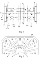
Figur 1- zeigt das Schema der Kühlluftführung über die gesamte Länge einer Maschine
Figur 2- zeigt eine Axialansicht des Querschnittes durch eine elektrische Maschine, die mit dem erfindungsgemäßen Ständerkühlsystem versehen ist (Schnitt A-A)
Figur 3- zeigt eine geviertelte Axialansicht auf die beiden Rahmen Rlund R2 und die Draufsicht auf die Form eines
Ständerblechpaketes 4eines Läuferblechpaketes 5 und auf eine Gestaltungsform eines Trenn- und Umlenkbleches TB Figur 4- zeigt eine Radialansicht durch ein Maschinenende (Schnitt B-B und Schnitt C-C)
- FIG. 1
- shows the scheme of the cooling air duct over the entire length of a machine
- FIG. 2
- shows an axial view of the cross section through an electric machine, which is provided with the stator cooling system according to the invention (section AA)
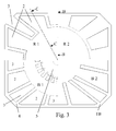
- FIG. 3
- shows a quartered axial view of the two frame Rlund R2 and the top view of the shape of a
stator core 4 of arotor core 5 and a design of a separating and deflecting plate TB - FIG. 4
- shows a radial view through a machine end (section BB and section CC)
Das Schema der fremdbeaufschlagten Kühlluftführung als Durchzugskühlung über die gesamte Länge einer Maschine mit dem neuartigen Ständerkühlsystem ist in
- Zuführung axial mittels Gebläse G1 der A Seite in den Luftsammelraum LS der A Seite und umströmen und kühlen der Wickelköpfe WK, sowohl des Ständers als auch des Läufers
- weiter axial durch die
Aussparungen 2 zur Kühlluftzuführung durch den Rahmen R2 und R1 - weiter durch axiale Kühlkanäle
AK als Zuströmkanäle 2 in den einzelnen Teilblechpaketen TP - bis in das letzte Teilblechpaket TB vor dem Zwischenblech ZB in der Maschinenmitte
- dabei wird jeweils ein Teil des zugeführten Kühlluftstromes in den Zwischenräumen zwischen den einzelnen Teilblechpaketen TP bedingt durch die Trenn- und Umlenkbleche TB nach innen zur Maschinenmitte durch die radialen Kühlkanäle RK auf die Läuferoberfläche des Lauferblechpaketes 5 radial umgelenkt, d. h. der Kühlluftstrom teilt sich in einzelne radiale Teilkühlluftstrome auf und kühl dabei einen Teil der Ständerwicklung
- die radial nach innen gerichteten Teilkühlluftströme werden in die Zwischenräume zwischen die Teilblechpakete des Läuferblechpakets 5gedrückt, umströmen die in das Läuferblechpaket eingelegte Wicklung im Läufer, werden durch die Läuferdrehung beschleunigt, umgelenkt und radial durch die radialen Kühlkanäle RK nach außen gedrückt
- die teilerwärmten Teilluftströme strömen nun in die nach außen führenden freien radialen Kühlkanäle RK und kühlen dabei den anderen Teil der Ständerwicklung
- die radial nach außen strömenden erwärmten Teilkühlluftströme werden zwischen den Teilblechpaketen TP bedingt durch die Trenn- und Umlenkbleche TB in die freien axialen Kühlkanäle AK, die
hier als Abströmkanälen 3 wirken, nach außen axial zur A Seite gerichtet umgelenkt und strömen über die radialen Ausströmkanäle RA radial aus der Maschine im Rahmen R1 aus.
- Feeding axially by means of blower G1 of the A side in the air collection space LS of the A side and flow around and cool the winding heads WK, both of the stator and the rotor
- further axially through the
recesses 2 for cooling air supply through the frame R2 and R1 - through axial cooling channels AK as
inflow channels 2 in the individual partial laminated cores TP - up to the last partial laminated core TB before the intermediate sheet ZB in the middle of the machine
- In this case, each part of the supplied cooling air flow is radially deflected in the spaces between the individual partial laminated core TP due to the separating and deflecting TB inward to the machine center through the radial cooling channels RK on the rotor surface of the
Lauferblechpaketes 5, ie, the cooling air flow is divided into individual radial Partial cooling air flow on and thereby cool a part of the stator winding - the radially inwardly directed partial cooling air streams are pressed into the interspaces between the partial laminated cores of the
rotor core 5, the winding in the rotor inserted in the rotor core is flowed around, accelerated by the armature rotation, and forced radially outwardly through the radial cooling channels RK - the partially heated partial air streams now flow into the outwardly leading free radial cooling channels RK and thereby cool the other part of the stator winding
- the radially outwardly flowing heated partial cooling air flows are deflected between the partial laminated cores TP conditionally by the separating and deflecting plates TB in the free axial cooling channels AK, which act here as
Abströmkanälen 3 directed axially towards the A side and flow radially through the radial outflow channels RA out of the machine in frame R1.
In
Der wesentliche Vorteil des erfindungsgemäßen Ständerkühlsystems ermöglicht neben der sehr intensiven Kühlung des Läufers und seiner Wicklung auch eine optimale Kühlung der beiden in den Figuren nicht dargestellten hoch beanspruchten Maschinenlager, da diese zuerst jeweils von der axial zugeführten Kühlluft umströmt und gekühlt werden. Bei dieser Lösung bildet sich im aktiven Lastbetrieb eine sehr konstante und gleichmäßige Temperatur über die gesamte Maschinenlänge heraus. Die Maschine kann durch diese hälftige Kühlung bei dieser neuartigen Konstruktion besonders lang gebaut werden. Dieses erfindungsgemäße Ständerkühlsystem ist anwendbar für gehäuselose rotierende elektrische Drehstrommaschinen mit sehr hohen Drehzahlen und sehr geringem Trägheitsmoment des Läufers.The main advantage of the stator cooling system according to the invention, in addition to the very intensive cooling of the rotor and its winding and optimum cooling of the two not shown in the figures highly stressed machine bearings, since they are first flows around each of the axially supplied cooling air and cooled. In this solution, a very constant and uniform temperature over the entire machine length forms in active load operation. The machine can be made particularly long by this half cooling in this novel construction. This stator cooling system according to the invention is applicable to housingless rotary electric three-phase machines with very high speeds and very low moment of inertia of the rotor.
- 11
- Pressrahmenpress frame
- 22
- Aussparungen zur KühlluftzuführungRecesses for cooling air supply
- 33
- Umlenktaschen zur KühlluftabführungDiverter pockets for cooling air discharge
- 44
- StänderblechpaketStator core
- 55
- LäuferblechpaketRotor core
- 66
- Maschinenachsemachine axis
- AKAK
- axialer Kühlkanalaxial cooling channel
-
B 1
B 1 -
Blechpaket 1
Sheet metal package 1 - B2B2
-
Blechpaket 2
Sheet metal package 2 - G1G1
- Gebläse A SeiteBlower A side
- G2G2
- Gebläse B SeiteBlower B side
- LSLS
- LuftsammelraumAir plenum
- R1R1
- Rahmenframe
- R2R2
-
Rahmen 2
Frame 2 - RARA
- Radiale AusströmkanäleRadial outflow channels
- RKRK
- Radiale KühlkanäleRadial cooling channels
- TBTB
- Trenn- und UmlenkblecheSeparating and deflecting plates
- TPTP
- TeilblechpaketeLaminate stack
- WKWK
- Wickelkopfwinding
- ZBFor example,
- Zwischenblechintermediate plate
Claims (14)
dadurch gekennzeichnet,
dass beidseitig massive einteilige Pressrahmen (1) ausgebildet und angeordnet sind,
in denen verteilt offene Aussparungen (2) zur Kühlluftzuführung vorgesehen sind,
im massiven Pressrahmen (1) verteilt offene Umlenktaschen (3) zur Kühlluftabführung radial nach außen und/oder zur teilweisen oder vollständigen Kühlluftabführung axial nach außen angeordnet sind,
oder beidseitig mehrteilige Pressrahmen (1) aus mindestens zwei einzelnen Rahmen (R1 und R2) angeordnet sind,
in denen verteilt offene Aussparungen (2) zur Kühlluftzuführung und offene Umlenktaschen (3) zur Kühlluftabführung radial nach außen und/oder zur teilweisen oder vollständigen Kühlluftabführung axial nach außen angeordnet sind,
zwischen den Teilblechpaketen (TP) radial nach innen wirkende Trenn- und Umlenkbleche (TB) angeordnet sind,
die Teilblechpakete (TP) durch die Trenn- und Umlenkbleche (TB) voneinander definiert beabstandet angeordnet sind,
die Umlenktaschen (3) zur Maschinenachse (6) hin radial geschlossen ausgebildet sind,
die Aussparungen (2) zur Kühlluftzuführung und die Umlenktaschen (3) zur Kühlluftabführung so groß ausgebildet sind, dass sie jeweils einen oder mehrere axiale Kühlkanäle (AK) umfassen, die Aussparungen (2) zur Kühlluftzuführung und die Umlenktaschen (3) zur Kühlluftabführung verteilt im Pressrahmen (1) angeordnet sind
und in der Maschinenmitte ein durchgehendes Zwischenblech (ZB) angeordnet ist.Stand cooling system for a housing-free rotating electrical machine with draft cooling, with a stator core (4) consisting of at least two partial laminated cores (TP) and outside of the stator core (4) arranged massive press frame (1) and axially distributed over the circumference designed as inflow and outflow channels cooling channels in the stator core (4) and on both sides axial cooling air supply via separate blowers (1 and 2),
characterized,
that solid one-piece press frames (1) are formed and arranged on both sides,
in which distributed open recesses (2) are provided for cooling air supply,
in the solid press frame (1) distributed Umlenktaschen open (3) for cooling air discharge radially outward and / or for partial or complete cooling air discharge axially outward,
or multipart press frames (1) of at least two individual frames (R1 and R2) are arranged on both sides,
in which distributed open recesses (2) for cooling air supply and open Umlenktaschen (3) are arranged for cooling air discharge radially outward and / or for partial or complete cooling air discharge axially outward,
between the partial laminated cores (TP) radially inwardly acting separating and deflecting plates (TB) are arranged,
the partial laminated cores (TP) are spaced apart from one another by the separating and deflecting plates (TB),
the deflecting pockets (3) are designed to be radially closed towards the machine axis (6),
the recesses (2) for cooling air supply and Umlenktaschen (3) are designed for cooling air discharge so large that they each comprise one or more axial cooling channels (AK), the recesses (2) for cooling air supply and Umlenktaschen (3) distributed to the cooling air discharge in the Press frame (1) are arranged
and in the machine center, a continuous intermediate plate (ZB) is arranged.
dadurch gekennzeichnet,
dass beidseitig massive einteilige Pressrahmen (1) ausgebildet und angeordnet sind,
in denen verteilt radial nach innen offene Aussparungen (2) zur Kühlluftzuführung vorgesehen sind, im massiven Pressrahmen (1) verteilt offene Umlenktaschen (3) zur Kühlluftabführung radial nach außen angeordnet sind,
oder die beidseitigen Pressrahmen (1) aus mindestens zwei einzelnen Rahmen (R1 und R2) bestehen,
in denen verteilt radial nach innen offene Aussparungen (2) zur Kühlluftzuführung und offene Umlenktaschen (3) zur Kühlluftabführung radial nach außen angeordnet sind,
zwischen den Teilblechpaketen (TP) radial nach innen wirkende Trenn- und Umlenkbleche (TB) angeordnet sind,
die Teilblechpakete (TP) durch die Trenn- und Umlenkbleche (TB) voneinander definiert beabstandet angeordnet sind,
die Umlenktaschen (3) zur Maschinenachse (6) hin radial geschlossen ausgebildet sind,
die Aussparungen (2) zur Kühlluftzuführung und die Umlenktaschen (3) zur Kühlluftabführung so groß ausgebildet sind, dass sie jeweils einen oder mehrere axiale Kühlkanäle (AK) umfassen die Aussparungen (2) zur Kühlluftzuführung und die Umlenktaschen (3) zur Kühlluftabführung abwechselnd verteilt im Pressrahmen (1) angeordnet sind
und in der Maschinenmitte ein durchgehendes Zwischenblech (ZB) angeordnet ist.Stand cooling system according to claim 1,
characterized,
that solid one-piece press frames (1) are formed and arranged on both sides,
in which distributed radially inwardly open recesses (2) are provided for cooling air supply in the solid press frame (1) distributed Umlenktaschen (3) are arranged for cooling air discharge radially outward,
or the press frames (1) on both sides consist of at least two individual frames (R1 and R2),
in which distributed radially inwardly open recesses (2) for cooling air supply and open Umlenktaschen (3) are arranged for cooling air discharge radially outward,
between the partial laminated cores (TP) radially inwardly acting separating and deflecting plates (TB) are arranged,
the partial laminated cores (TP) are spaced apart from one another by the separating and deflecting plates (TB),
the deflecting pockets (3) are designed to be radially closed towards the machine axis (6),
the recesses (2) for cooling air supply and Umlenktaschen (3) for cooling air discharge are formed so large that they each comprise one or more axial cooling channels (AK) the recesses (2) for cooling air supply and Umlenktaschen (3) for cooling air discharge alternately distributed in Press frame (1) are arranged
and in the machine center, a continuous intermediate plate (ZB) is arranged.
dadurch gekennzeichnet,
dass ein oder beide Rahmen (1 oder 2) der Pressrahmen (1) aus entsprechend geformten Einzelblechen geschichtet sind.Stand cooling system according to claim 1 or 2,
characterized,
in that one or both frames (1 or 2) of the pressing frames (1) are laminated from correspondingly shaped individual sheets.
dadurch gekennzeichnet,
dass die Querschnitte der axialen Kühlkanäle (AK) symmetrisch auf einem Bereich eines äußeren Radius des Ständerblechpaketes (1) verteilt mit etwa gleichem axialen Querschnitt angeordnet sind.Stand cooling system according to claim 1 or 2,
characterized,
that the cross sections of the axial cooling channels (AK) are symmetrically distributed on a portion of an outer radius of the stator core (1) arranged at approximately the same axial cross section.
dadurch gekennzeichnet,
dass die Aussparungen (2) zur Kühlluftzuführung im Pressrahmen (1) so groß dimensioniert und ausgebildet sind, dass diese mehrere nebeneinander liegende axiale Kühlkanäle (AK) des Standerblechpaketes (4) umfassen, wobei die Umlenktaschen (3) zur Kühlluftabführung weniger oder die gleiche Anzahl oder mehr axiale Kühlkanäle umfassen.Stand cooling system according to claim 1, 2 or 4,
characterized,
that the recesses (2) for cooling air supply in the press frame (1) are dimensioned and formed so large that they comprise a plurality of adjacent axial cooling channels (AK) of the stator lamination stack (4), wherein the Umlenktaschen (3) for cooling air discharge less or the same number or more axial cooling channels.
dadurch gekennzeichnet,
dass die Dicke der zwischen den Teilblechpaketen (TP) angeordneten Trenn- und Umlenkbleche (TB) von den Ständerblechpaketenden her in Richtung zur Ständerblechpaketmitte hin zunimmt.Stand cooling system according to claim 1 or 2,
characterized,
in that the thickness of the separating and deflecting plates (TB) arranged between the partial laminated cores (TP) increases in the direction of the stator laminated core from the stator laminated core ends.
dadurch gekennzeichnet,
dass die Trenn- und Umlenkbleche (TB) in den Zwischenräumen zwischen den Teilblechpaketen (TP) aus einem oder mehreren gestanzten Distanzblechen oder aus einem einzelnen breiteren Formteil bestehen.Stand cooling system according to claim 1, 2 or 6,
characterized,
in that the separating and deflecting plates (TB) in the intermediate spaces between the partial laminated cores (TP) consist of one or more punched spacer plates or of a single, wider molded part.
dadurch gekennzeichnet,
dass der Querschnitt der axialen Kühlkanäle (AK) unterschiedlich groß ausgebildet ist.Stand cooling system according to claim 1, 2, 4 or 5,
characterized,
that the cross section of the axial cooling channels (AK) is formed differently large.
dadurch gekennzeichnet,
dass die Aussparungen (2) zur Kühlluftzuführung im Pressrahmen (1) und die Umlenktaschen (3) im Querschnitt unterschiedlich groß ausgebildet sind,
wobei die Aussparungen (2), durch die die Kühlluft zuströmt, sich über eine andere Zahl von mehreren Nut- oder Zahnteilungen erstrecken, als die Umlenktaschen (3), durch die die Kühlluft abströmt.Stand cooling system according to claim 1 or 2,
characterized,
that the recesses (2) for cooling air supply in the press frame (1) and the Umlenktaschen (3) are formed differently in cross-section,
wherein the recesses (2) through which the cooling air flows, extend over a different number of a plurality of groove or tooth pitches, as the Umlenktaschen (3) through which the cooling air flows.
dadurch gekennzeichnet,
dass das Zwischenblech (ZB) so dick dimensioniert ist, dass im Zwischenblech (ZB) zusätzliche Umlenknuten zur Kühlluftumkehr in die axialen Kühlkanäle (AK) angeordnet sind.Stand cooling system according to claim 1 or 2,
characterized,
that the intermediate plate (ZB) is dimensioned so thick that in the intermediate plate (ZB) additional Umlenknuten for cooling air reversal in the axial cooling channels (AK) are arranged.
dadurch gekennzeichnet,
dass die in den links und rechts vom Zwischenblech (ZB) angeordneten Teilblechpaketen (TP) im aktiven Blechmaterial Umlenknuten zur Kühlluftumkehr in die axialen Kühlkanäle (AK) angeordnet sind.Stand cooling system according to claim 1 or 2,
characterized,
that in the left and right of the intermediate plate (ZB) arranged partial laminated cores (TP) are arranged in the active sheet material Umlenknuten for cooling air reversal in the axial cooling channels (AK).
dadurch gekennzeichnet,
dass das Zwischenblech (ZB) so dick dimensioniert ist, dass im Zwischenblech (ZB) zusätzlich radiale Öffnungen nach außen zum Maschinenmantel hin zur Kühlluftableitung angeordnet sind.Stand cooling system according to claim 1 or 2,
characterized,
that the intermediate plate (ZB) is dimensioned so thick that in the intermediate plate (ZB) additional radial openings are arranged outwardly to the machine casing towards the cooling air discharge.
dadurch gekennzeichnet,
dass in den links und rechts vom Zwischenblech (ZB) angeordneten Teilblechpaketen (TP) im aktiven Blechmaterial radiale Öffnungen nach außen zum Maschinenmantel hin zur Kühlluftableitung angeordnet sind.Stand cooling system according to claim 1 or 2,
characterized,
that in the left and right of the intermediate plate (ZB) arranged partial laminated cores (TP) in the active sheet metal material radial openings are arranged outwardly to the machine casing towards the cooling air discharge.
dadurch gekennzeichnet,
dass links und rechts vom Zwischenblech (ZB) unmittelbar anliegend je ein Trenn- und Umlenkblech (TB) angeordnet ist.Stand cooling system according to claim 1 or 2,
characterized,
that a separating and deflecting plate (TB) is arranged directly adjacent to the left and right of the intermediate plate (ZB).
Applications Claiming Priority (2)
| Application Number | Priority Date | Filing Date | Title |
|---|---|---|---|
| DE102008037546 | 2008-11-10 | ||
| DE102009043959A DE102009043959A1 (en) | 2008-11-10 | 2009-09-08 | Stator cooling system for cooling three-phase electric motor, has cooling air supply openings and cooling air discharge deflection slot arranged on pressing frame, and intermediate plate arranged in center of system |
Publications (3)
| Publication Number | Publication Date |
|---|---|
| EP2230746A2 true EP2230746A2 (en) | 2010-09-22 |
| EP2230746A3 EP2230746A3 (en) | 2016-12-21 |
| EP2230746B1 EP2230746B1 (en) | 2020-09-30 |
Family
ID=42105335
Family Applications (1)
| Application Number | Title | Priority Date | Filing Date |
|---|---|---|---|
| EP09401037.8A Active EP2230746B1 (en) | 2008-11-10 | 2009-11-10 | Stator cooling system for a rotating electric machine without a housing |
Country Status (2)
| Country | Link |
|---|---|
| EP (1) | EP2230746B1 (en) |
| DE (1) | DE102009043959A1 (en) |
Families Citing this family (1)
| Publication number | Priority date | Publication date | Assignee | Title |
|---|---|---|---|---|
| DE102011053299A1 (en) * | 2011-09-06 | 2013-03-07 | Antriebstechnik Katt Hessen Gmbh | Cooling system for a highly used high-speed rotating synchronous electric machine |
Citations (11)
| Publication number | Priority date | Publication date | Assignee | Title |
|---|---|---|---|---|
| US3171996A (en) | 1960-01-07 | 1965-03-02 | Gen Electric | Stator air duct design |
| DE2318090B2 (en) | 1973-04-07 | 1977-06-16 | Licentia Patent-Verwaltungs-Gmbh, 6000 Frankfurt | COOLING SYSTEM FOR A GAS COOLED ELECTRIC MACHINE |
| EP0118802A1 (en) | 1983-03-10 | 1984-09-19 | BBC Aktiengesellschaft Brown, Boveri & Cie. | Gas-cooled alternating current machine |
| DE2953800C2 (en) | 1979-08-30 | 1986-02-13 | Šurygin, Sergej Jakovlevič | Electric machine with gas cooling |
| EP0522210A1 (en) | 1991-07-12 | 1993-01-13 | Siemens Aktiengesellschaft | Cooling system of a rotating electrical machine and electrical machine for carrying out such a system |
| DE4320559A1 (en) | 1993-06-21 | 1994-12-22 | Siemens Ag | Electrical machine having an internally cooled rotor |
| EP0824287A1 (en) | 1996-08-12 | 1998-02-18 | Siemens Aktiengesellschaft | Electrical machine with liquid-cooled inner-rotor |
| DE19824202C1 (en) | 1998-05-29 | 1999-09-30 | Siemens Ag | Liquid-cooled electric internal rotor machine e.g. for traction motor of rail-vehicles |
| DE10054338C2 (en) | 2000-11-02 | 2003-11-27 | Antriebstechnik Katt Hessen Gm | Cooling system for low inertia rotating electrical machine |
| DE10317593A1 (en) | 2003-04-16 | 2004-11-18 | Siemens Ag | Electrical machine with cooled stator and rotor laminated core and windings |
| DE102004013133A1 (en) | 2004-03-17 | 2005-10-13 | Siemens Ag | Electric machine with improved cooling and cooling method |
Family Cites Families (3)
| Publication number | Priority date | Publication date | Assignee | Title |
|---|---|---|---|---|
| FR626107A (en) * | 1925-12-10 | 1927-08-30 | Aeg | Device for cooling electrical machines by means of a gaseous cooling medium |
| GB0118565D0 (en) * | 2001-07-31 | 2001-09-19 | Alstom | Electric machine component cooling |
| DE102006049188B3 (en) * | 2006-10-14 | 2008-03-27 | Antriebstechnik Katt Hessen Gmbh | Cooling system for rotary electrical machine i.e. three-phase machine, has radial housing discharge openings arranged with open channels during construction of housing at points of stator partial laminated cores |
-
2009
- 2009-09-08 DE DE102009043959A patent/DE102009043959A1/en not_active Withdrawn
- 2009-11-10 EP EP09401037.8A patent/EP2230746B1/en active Active
Patent Citations (11)
| Publication number | Priority date | Publication date | Assignee | Title |
|---|---|---|---|---|
| US3171996A (en) | 1960-01-07 | 1965-03-02 | Gen Electric | Stator air duct design |
| DE2318090B2 (en) | 1973-04-07 | 1977-06-16 | Licentia Patent-Verwaltungs-Gmbh, 6000 Frankfurt | COOLING SYSTEM FOR A GAS COOLED ELECTRIC MACHINE |
| DE2953800C2 (en) | 1979-08-30 | 1986-02-13 | Šurygin, Sergej Jakovlevič | Electric machine with gas cooling |
| EP0118802A1 (en) | 1983-03-10 | 1984-09-19 | BBC Aktiengesellschaft Brown, Boveri & Cie. | Gas-cooled alternating current machine |
| EP0522210A1 (en) | 1991-07-12 | 1993-01-13 | Siemens Aktiengesellschaft | Cooling system of a rotating electrical machine and electrical machine for carrying out such a system |
| DE4320559A1 (en) | 1993-06-21 | 1994-12-22 | Siemens Ag | Electrical machine having an internally cooled rotor |
| EP0824287A1 (en) | 1996-08-12 | 1998-02-18 | Siemens Aktiengesellschaft | Electrical machine with liquid-cooled inner-rotor |
| DE19824202C1 (en) | 1998-05-29 | 1999-09-30 | Siemens Ag | Liquid-cooled electric internal rotor machine e.g. for traction motor of rail-vehicles |
| DE10054338C2 (en) | 2000-11-02 | 2003-11-27 | Antriebstechnik Katt Hessen Gm | Cooling system for low inertia rotating electrical machine |
| DE10317593A1 (en) | 2003-04-16 | 2004-11-18 | Siemens Ag | Electrical machine with cooled stator and rotor laminated core and windings |
| DE102004013133A1 (en) | 2004-03-17 | 2005-10-13 | Siemens Ag | Electric machine with improved cooling and cooling method |
Also Published As
| Publication number | Publication date |
|---|---|
| EP2230746A3 (en) | 2016-12-21 |
| EP2230746B1 (en) | 2020-09-30 |
| DE102009043959A1 (en) | 2010-05-20 |
Similar Documents
| Publication | Publication Date | Title |
|---|---|---|
| DE102008064495B3 (en) | Electric machine with several cooling streams and cooling process | |
| EP2568576A2 (en) | Cooling system for a highly utilized high-speed rotating electric synchronous machine | |
| EP2368308B1 (en) | Electrical motor havingaxial and radially offsetted cooling stream and related method | |
| EP3433919B1 (en) | Rotor segment of an electric machine | |
| EP2109207B1 (en) | Liquid cooled electric machine and process for cooling an electric machine | |
| EP2918000B1 (en) | Electric machine having internal air cooling | |
| DE102011056007A1 (en) | Cooling system for a rotating electrical machine of highest power density | |
| EP2076956B1 (en) | Cooling system for highly utilized rotating electrical machines | |
| EP1248349A2 (en) | Asynchronous electric motor | |
| WO2004027960A1 (en) | Electrical machine with a stator with cooled winding bars | |
| DE102004013133A1 (en) | Electric machine with improved cooling and cooling method | |
| DE2608291A1 (en) | GAS-COOLED GENERATOR ROTOR WITH INCREASED VENTILATION | |
| DE102016210930A1 (en) | Rotor laminated core for an electric machine | |
| EP1241772A1 (en) | Air-cooled electric rotary machine | |
| EP4008047A1 (en) | Electric drive unit, hybrid module, and drive assembly for a motor vehicle | |
| DE3504782A1 (en) | Rotor laminate stack and/or stator laminate stack for electrical machines | |
| EP2230746B1 (en) | Stator cooling system for a rotating electric machine without a housing | |
| DE102017202801A1 (en) | Rotor core for a rotor | |
| EP1204193B1 (en) | Cooling system for a low inertia rotating electric machine | |
| EP0889572A2 (en) | Electric machine | |
| WO2021209086A1 (en) | Rotor of an electric rotating machine, and electric rotating machine | |
| DE4337463C2 (en) | Stand with ventilation device for electrical machine without housing | |
| DE4413389A1 (en) | Electrical machine | |
| EP2639937B1 (en) | Rotor for an electrodynamic machine | |
| DE102006020149A1 (en) | Synchronous salient pole machine e.g. ring motor, for use in ball mill, has yoke with yoke section arranged between two salient poles, where yoke section has radial air passage that radially separates air portion |
Legal Events
| Date | Code | Title | Description |
|---|---|---|---|
| PUAI | Public reference made under article 153(3) epc to a published international application that has entered the european phase |
Free format text: ORIGINAL CODE: 0009012 |
|
| AK | Designated contracting states |
Kind code of ref document: A2 Designated state(s): AT BE BG CH CY CZ DE DK EE ES FI FR GB GR HR HU IE IS IT LI LT LU LV MC MK MT NL NO PL PT RO SE SI SK SM TR |
|
| AX | Request for extension of the european patent |
Extension state: AL BA RS |
|
| PUAL | Search report despatched |
Free format text: ORIGINAL CODE: 0009013 |
|
| AK | Designated contracting states |
Kind code of ref document: A3 Designated state(s): AT BE BG CH CY CZ DE DK EE ES FI FR GB GR HR HU IE IS IT LI LT LU LV MC MK MT NL NO PL PT RO SE SI SK SM TR |
|
| AX | Request for extension of the european patent |
Extension state: AL BA RS |
|
| RIC1 | Information provided on ipc code assigned before grant |
Ipc: H02K 9/04 20060101ALN20161117BHEP Ipc: H02K 1/20 20060101AFI20161117BHEP Ipc: H02K 1/32 20060101ALN20161117BHEP |
|
| STAA | Information on the status of an ep patent application or granted ep patent |
Free format text: STATUS: REQUEST FOR EXAMINATION WAS MADE |
|
| 17P | Request for examination filed |
Effective date: 20170426 |
|
| STAA | Information on the status of an ep patent application or granted ep patent |
Free format text: STATUS: EXAMINATION IS IN PROGRESS |
|
| 17Q | First examination report despatched |
Effective date: 20180918 |
|
| GRAP | Despatch of communication of intention to grant a patent |
Free format text: ORIGINAL CODE: EPIDOSNIGR1 |
|
| STAA | Information on the status of an ep patent application or granted ep patent |
Free format text: STATUS: GRANT OF PATENT IS INTENDED |
|
| RIC1 | Information provided on ipc code assigned before grant |
Ipc: H02K 9/04 20060101ALN20200122BHEP Ipc: H02K 1/20 20060101AFI20200122BHEP Ipc: H02K 1/32 20060101ALN20200122BHEP |
|
| INTG | Intention to grant announced |
Effective date: 20200217 |
|
| GRAJ | Information related to disapproval of communication of intention to grant by the applicant or resumption of examination proceedings by the epo deleted |
Free format text: ORIGINAL CODE: EPIDOSDIGR1 |
|
| STAA | Information on the status of an ep patent application or granted ep patent |
Free format text: STATUS: EXAMINATION IS IN PROGRESS |
|
| INTC | Intention to grant announced (deleted) | ||
| GRAS | Grant fee paid |
Free format text: ORIGINAL CODE: EPIDOSNIGR3 |
|
| STAA | Information on the status of an ep patent application or granted ep patent |
Free format text: STATUS: GRANT OF PATENT IS INTENDED |
|
| GRAP | Despatch of communication of intention to grant a patent |
Free format text: ORIGINAL CODE: EPIDOSNIGR1 |
|
| RIC1 | Information provided on ipc code assigned before grant |
Ipc: H02K 9/04 20060101ALN20200709BHEP Ipc: H02K 1/20 20060101AFI20200709BHEP Ipc: H02K 1/32 20060101ALN20200709BHEP |
|
| INTG | Intention to grant announced |
Effective date: 20200724 |
|
| GRAA | (expected) grant |
Free format text: ORIGINAL CODE: 0009210 |
|
| STAA | Information on the status of an ep patent application or granted ep patent |
Free format text: STATUS: THE PATENT HAS BEEN GRANTED |
|
| AK | Designated contracting states |
Kind code of ref document: B1 Designated state(s): AT BE BG CH CY CZ DE DK EE ES FI FR GB GR HR HU IE IS IT LI LT LU LV MC MK MT NL NO PL PT RO SE SI SK SM TR |
|
| REG | Reference to a national code |
Ref country code: CH Ref legal event code: EP Ref country code: GB Ref legal event code: FG4D Free format text: NOT ENGLISH |
|
| REG | Reference to a national code |
Ref country code: DE Ref legal event code: R096 Ref document number: 502009016279 Country of ref document: DE Ref country code: AT Ref legal event code: REF Ref document number: 1319801 Country of ref document: AT Kind code of ref document: T Effective date: 20201015 |
|
| REG | Reference to a national code |
Ref country code: IE Ref legal event code: FG4D Free format text: LANGUAGE OF EP DOCUMENT: GERMAN |
|
| PG25 | Lapsed in a contracting state [announced via postgrant information from national office to epo] |
Ref country code: GR Free format text: LAPSE BECAUSE OF FAILURE TO SUBMIT A TRANSLATION OF THE DESCRIPTION OR TO PAY THE FEE WITHIN THE PRESCRIBED TIME-LIMIT Effective date: 20201231 Ref country code: NO Free format text: LAPSE BECAUSE OF FAILURE TO SUBMIT A TRANSLATION OF THE DESCRIPTION OR TO PAY THE FEE WITHIN THE PRESCRIBED TIME-LIMIT Effective date: 20201230 Ref country code: HR Free format text: LAPSE BECAUSE OF FAILURE TO SUBMIT A TRANSLATION OF THE DESCRIPTION OR TO PAY THE FEE WITHIN THE PRESCRIBED TIME-LIMIT Effective date: 20200930 Ref country code: SE Free format text: LAPSE BECAUSE OF FAILURE TO SUBMIT A TRANSLATION OF THE DESCRIPTION OR TO PAY THE FEE WITHIN THE PRESCRIBED TIME-LIMIT Effective date: 20200930 Ref country code: FI Free format text: LAPSE BECAUSE OF FAILURE TO SUBMIT A TRANSLATION OF THE DESCRIPTION OR TO PAY THE FEE WITHIN THE PRESCRIBED TIME-LIMIT Effective date: 20200930 Ref country code: BG Free format text: LAPSE BECAUSE OF FAILURE TO SUBMIT A TRANSLATION OF THE DESCRIPTION OR TO PAY THE FEE WITHIN THE PRESCRIBED TIME-LIMIT Effective date: 20201230 |
|
| PG25 | Lapsed in a contracting state [announced via postgrant information from national office to epo] |
Ref country code: LV Free format text: LAPSE BECAUSE OF FAILURE TO SUBMIT A TRANSLATION OF THE DESCRIPTION OR TO PAY THE FEE WITHIN THE PRESCRIBED TIME-LIMIT Effective date: 20200930 |
|
| REG | Reference to a national code |
Ref country code: NL Ref legal event code: MP Effective date: 20200930 |
|
| REG | Reference to a national code |
Ref country code: LT Ref legal event code: MG4D |
|
| PG25 | Lapsed in a contracting state [announced via postgrant information from national office to epo] |
Ref country code: EE Free format text: LAPSE BECAUSE OF FAILURE TO SUBMIT A TRANSLATION OF THE DESCRIPTION OR TO PAY THE FEE WITHIN THE PRESCRIBED TIME-LIMIT Effective date: 20200930 Ref country code: RO Free format text: LAPSE BECAUSE OF FAILURE TO SUBMIT A TRANSLATION OF THE DESCRIPTION OR TO PAY THE FEE WITHIN THE PRESCRIBED TIME-LIMIT Effective date: 20200930 Ref country code: SM Free format text: LAPSE BECAUSE OF FAILURE TO SUBMIT A TRANSLATION OF THE DESCRIPTION OR TO PAY THE FEE WITHIN THE PRESCRIBED TIME-LIMIT Effective date: 20200930 Ref country code: LT Free format text: LAPSE BECAUSE OF FAILURE TO SUBMIT A TRANSLATION OF THE DESCRIPTION OR TO PAY THE FEE WITHIN THE PRESCRIBED TIME-LIMIT Effective date: 20200930 Ref country code: NL Free format text: LAPSE BECAUSE OF FAILURE TO SUBMIT A TRANSLATION OF THE DESCRIPTION OR TO PAY THE FEE WITHIN THE PRESCRIBED TIME-LIMIT Effective date: 20200930 Ref country code: PT Free format text: LAPSE BECAUSE OF FAILURE TO SUBMIT A TRANSLATION OF THE DESCRIPTION OR TO PAY THE FEE WITHIN THE PRESCRIBED TIME-LIMIT Effective date: 20210201 |
|
| PGFP | Annual fee paid to national office [announced via postgrant information from national office to epo] |
Ref country code: IT Payment date: 20210111 Year of fee payment: 12 |
|
| PG25 | Lapsed in a contracting state [announced via postgrant information from national office to epo] |
Ref country code: ES Free format text: LAPSE BECAUSE OF FAILURE TO SUBMIT A TRANSLATION OF THE DESCRIPTION OR TO PAY THE FEE WITHIN THE PRESCRIBED TIME-LIMIT Effective date: 20200930 Ref country code: IS Free format text: LAPSE BECAUSE OF FAILURE TO SUBMIT A TRANSLATION OF THE DESCRIPTION OR TO PAY THE FEE WITHIN THE PRESCRIBED TIME-LIMIT Effective date: 20210130 Ref country code: PL Free format text: LAPSE BECAUSE OF FAILURE TO SUBMIT A TRANSLATION OF THE DESCRIPTION OR TO PAY THE FEE WITHIN THE PRESCRIBED TIME-LIMIT Effective date: 20200930 |
|
| PG25 | Lapsed in a contracting state [announced via postgrant information from national office to epo] |
Ref country code: SK Free format text: LAPSE BECAUSE OF FAILURE TO SUBMIT A TRANSLATION OF THE DESCRIPTION OR TO PAY THE FEE WITHIN THE PRESCRIBED TIME-LIMIT Effective date: 20200930 Ref country code: MC Free format text: LAPSE BECAUSE OF FAILURE TO SUBMIT A TRANSLATION OF THE DESCRIPTION OR TO PAY THE FEE WITHIN THE PRESCRIBED TIME-LIMIT Effective date: 20200930 |
|
| REG | Reference to a national code |
Ref country code: CH Ref legal event code: PL |
|
| REG | Reference to a national code |
Ref country code: DE Ref legal event code: R097 Ref document number: 502009016279 Country of ref document: DE |
|
| PG25 | Lapsed in a contracting state [announced via postgrant information from national office to epo] |
Ref country code: LU Free format text: LAPSE BECAUSE OF NON-PAYMENT OF DUE FEES Effective date: 20201110 |
|
| PLBE | No opposition filed within time limit |
Free format text: ORIGINAL CODE: 0009261 |
|
| STAA | Information on the status of an ep patent application or granted ep patent |
Free format text: STATUS: NO OPPOSITION FILED WITHIN TIME LIMIT |
|
| REG | Reference to a national code |
Ref country code: BE Ref legal event code: MM Effective date: 20201130 |
|
| GBPC | Gb: european patent ceased through non-payment of renewal fee |
Effective date: 20201230 |
|
| PG25 | Lapsed in a contracting state [announced via postgrant information from national office to epo] |
Ref country code: CH Free format text: LAPSE BECAUSE OF NON-PAYMENT OF DUE FEES Effective date: 20201130 Ref country code: DK Free format text: LAPSE BECAUSE OF FAILURE TO SUBMIT A TRANSLATION OF THE DESCRIPTION OR TO PAY THE FEE WITHIN THE PRESCRIBED TIME-LIMIT Effective date: 20200930 Ref country code: LI Free format text: LAPSE BECAUSE OF NON-PAYMENT OF DUE FEES Effective date: 20201130 |
|
| 26N | No opposition filed |
Effective date: 20210701 |
|
| PG25 | Lapsed in a contracting state [announced via postgrant information from national office to epo] |
Ref country code: IE Free format text: LAPSE BECAUSE OF NON-PAYMENT OF DUE FEES Effective date: 20201110 Ref country code: FR Free format text: LAPSE BECAUSE OF NON-PAYMENT OF DUE FEES Effective date: 20201130 |
|
| PG25 | Lapsed in a contracting state [announced via postgrant information from national office to epo] |
Ref country code: SI Free format text: LAPSE BECAUSE OF FAILURE TO SUBMIT A TRANSLATION OF THE DESCRIPTION OR TO PAY THE FEE WITHIN THE PRESCRIBED TIME-LIMIT Effective date: 20200930 Ref country code: GB Free format text: LAPSE BECAUSE OF NON-PAYMENT OF DUE FEES Effective date: 20201230 |
|
| PG25 | Lapsed in a contracting state [announced via postgrant information from national office to epo] |
Ref country code: IS Free format text: LAPSE BECAUSE OF FAILURE TO SUBMIT A TRANSLATION OF THE DESCRIPTION OR TO PAY THE FEE WITHIN THE PRESCRIBED TIME-LIMIT Effective date: 20210130 Ref country code: TR Free format text: LAPSE BECAUSE OF FAILURE TO SUBMIT A TRANSLATION OF THE DESCRIPTION OR TO PAY THE FEE WITHIN THE PRESCRIBED TIME-LIMIT Effective date: 20200930 Ref country code: MT Free format text: LAPSE BECAUSE OF FAILURE TO SUBMIT A TRANSLATION OF THE DESCRIPTION OR TO PAY THE FEE WITHIN THE PRESCRIBED TIME-LIMIT Effective date: 20200930 Ref country code: CY Free format text: LAPSE BECAUSE OF FAILURE TO SUBMIT A TRANSLATION OF THE DESCRIPTION OR TO PAY THE FEE WITHIN THE PRESCRIBED TIME-LIMIT Effective date: 20200930 |
|
| PG25 | Lapsed in a contracting state [announced via postgrant information from national office to epo] |
Ref country code: MK Free format text: LAPSE BECAUSE OF FAILURE TO SUBMIT A TRANSLATION OF THE DESCRIPTION OR TO PAY THE FEE WITHIN THE PRESCRIBED TIME-LIMIT Effective date: 20200930 |
|
| PG25 | Lapsed in a contracting state [announced via postgrant information from national office to epo] |
Ref country code: BE Free format text: LAPSE BECAUSE OF NON-PAYMENT OF DUE FEES Effective date: 20201130 |
|
| PG25 | Lapsed in a contracting state [announced via postgrant information from national office to epo] |
Ref country code: IT Free format text: LAPSE BECAUSE OF NON-PAYMENT OF DUE FEES Effective date: 20211110 |
|
| PGFP | Annual fee paid to national office [announced via postgrant information from national office to epo] |
Ref country code: CZ Payment date: 20231108 Year of fee payment: 15 Ref country code: AT Payment date: 20231106 Year of fee payment: 15 |
|
| PGFP | Annual fee paid to national office [announced via postgrant information from national office to epo] |
Ref country code: DE Payment date: 20240125 Year of fee payment: 15 |