EP2230000A1 - Vorrichtung und Verfahren zur Abgasbehandlung mit Ammoniaklösung - Google Patents
Vorrichtung und Verfahren zur Abgasbehandlung mit Ammoniaklösung Download PDFInfo
- Publication number
- EP2230000A1 EP2230000A1 EP09179658A EP09179658A EP2230000A1 EP 2230000 A1 EP2230000 A1 EP 2230000A1 EP 09179658 A EP09179658 A EP 09179658A EP 09179658 A EP09179658 A EP 09179658A EP 2230000 A1 EP2230000 A1 EP 2230000A1
- Authority
- EP
- European Patent Office
- Prior art keywords
- stream
- ionic
- ammonia solution
- gas
- ammonia
- Prior art date
- Legal status (The legal status is an assumption and is not a legal conclusion. Google has not performed a legal analysis and makes no representation as to the accuracy of the status listed.)
- Granted
Links
- NLXLAEXVIDQMFP-UHFFFAOYSA-N Ammonium chloride Substances [NH4+].[Cl-] NLXLAEXVIDQMFP-UHFFFAOYSA-N 0.000 title claims abstract description 110
- VHUUQVKOLVNVRT-UHFFFAOYSA-N Ammonium hydroxide Chemical compound [NH4+].[OH-] VHUUQVKOLVNVRT-UHFFFAOYSA-N 0.000 title claims abstract description 110
- 235000011114 ammonium hydroxide Nutrition 0.000 title claims abstract description 110
- 238000000034 method Methods 0.000 title claims abstract description 50
- 239000003546 flue gas Substances 0.000 title description 34
- UGFAIRIUMAVXCW-UHFFFAOYSA-N Carbon monoxide Chemical compound [O+]#[C-] UGFAIRIUMAVXCW-UHFFFAOYSA-N 0.000 title description 33
- CURLTUGMZLYLDI-UHFFFAOYSA-N Carbon dioxide Chemical compound O=C=O CURLTUGMZLYLDI-UHFFFAOYSA-N 0.000 claims abstract description 486
- QGZKDVFQNNGYKY-UHFFFAOYSA-N Ammonia Chemical compound N QGZKDVFQNNGYKY-UHFFFAOYSA-N 0.000 claims abstract description 293
- 229910002092 carbon dioxide Inorganic materials 0.000 claims abstract description 243
- 239000001569 carbon dioxide Substances 0.000 claims abstract description 243
- 229910021529 ammonia Inorganic materials 0.000 claims abstract description 100
- 239000007788 liquid Substances 0.000 claims abstract description 89
- 239000012071 phase Substances 0.000 claims abstract description 46
- 239000007791 liquid phase Substances 0.000 claims abstract description 44
- XLYOFNOQVPJJNP-UHFFFAOYSA-N water Substances O XLYOFNOQVPJJNP-UHFFFAOYSA-N 0.000 claims description 84
- 229910001868 water Inorganic materials 0.000 claims description 79
- 239000006096 absorbing agent Substances 0.000 claims description 68
- 238000010438 heat treatment Methods 0.000 claims description 24
- 230000008929 regeneration Effects 0.000 claims description 17
- 238000011069 regeneration method Methods 0.000 claims description 17
- 239000007864 aqueous solution Substances 0.000 claims description 16
- 238000004064 recycling Methods 0.000 claims description 5
- 238000005485 electric heating Methods 0.000 claims description 4
- 239000000243 solution Substances 0.000 description 163
- 239000007789 gas Substances 0.000 description 84
- 229910000069 nitrogen hydride Inorganic materials 0.000 description 46
- 230000008569 process Effects 0.000 description 28
- 238000009835 boiling Methods 0.000 description 12
- 239000012530 fluid Substances 0.000 description 11
- 230000008901 benefit Effects 0.000 description 10
- 238000012856 packing Methods 0.000 description 10
- 238000012546 transfer Methods 0.000 description 10
- 238000004140 cleaning Methods 0.000 description 7
- 238000002485 combustion reaction Methods 0.000 description 7
- 238000010521 absorption reaction Methods 0.000 description 4
- 238000009825 accumulation Methods 0.000 description 4
- 238000010586 diagram Methods 0.000 description 4
- 239000000463 material Substances 0.000 description 4
- 239000012808 vapor phase Substances 0.000 description 4
- 238000010793 Steam injection (oil industry) Methods 0.000 description 3
- 229910000831 Steel Inorganic materials 0.000 description 3
- 239000007792 gaseous phase Substances 0.000 description 3
- 239000010959 steel Substances 0.000 description 3
- 238000010977 unit operation Methods 0.000 description 3
- -1 ammonium ions Chemical class 0.000 description 2
- 239000000356 contaminant Substances 0.000 description 2
- 239000000446 fuel Substances 0.000 description 2
- 238000012986 modification Methods 0.000 description 2
- 230000004048 modification Effects 0.000 description 2
- 238000010248 power generation Methods 0.000 description 2
- 230000009467 reduction Effects 0.000 description 2
- 230000001105 regulatory effect Effects 0.000 description 2
- 230000007704 transition Effects 0.000 description 2
- 239000002699 waste material Substances 0.000 description 2
- BVKZGUZCCUSVTD-UHFFFAOYSA-M Bicarbonate Chemical compound OC([O-])=O BVKZGUZCCUSVTD-UHFFFAOYSA-M 0.000 description 1
- BVKZGUZCCUSVTD-UHFFFAOYSA-L Carbonate Chemical compound [O-]C([O-])=O BVKZGUZCCUSVTD-UHFFFAOYSA-L 0.000 description 1
- 230000002745 absorbent Effects 0.000 description 1
- 239000002250 absorbent Substances 0.000 description 1
- 239000003245 coal Substances 0.000 description 1
- 239000000567 combustion gas Substances 0.000 description 1
- 238000010276 construction Methods 0.000 description 1
- 238000001816 cooling Methods 0.000 description 1
- 238000011161 development Methods 0.000 description 1
- 230000018109 developmental process Effects 0.000 description 1
- 238000010790 dilution Methods 0.000 description 1
- 239000012895 dilution Substances 0.000 description 1
- 239000000428 dust Substances 0.000 description 1
- 230000005611 electricity Effects 0.000 description 1
- 230000007613 environmental effect Effects 0.000 description 1
- 239000002803 fossil fuel Substances 0.000 description 1
- 238000002347 injection Methods 0.000 description 1
- 239000007924 injection Substances 0.000 description 1
- 239000002608 ionic liquid Substances 0.000 description 1
- 230000007935 neutral effect Effects 0.000 description 1
- 239000003921 oil Substances 0.000 description 1
- 239000002245 particle Substances 0.000 description 1
- 239000003415 peat Substances 0.000 description 1
- 239000002244 precipitate Substances 0.000 description 1
- 238000012545 processing Methods 0.000 description 1
- 238000000746 purification Methods 0.000 description 1
- 238000011084 recovery Methods 0.000 description 1
- 238000010992 reflux Methods 0.000 description 1
- 230000001172 regenerating effect Effects 0.000 description 1
- 239000002002 slurry Substances 0.000 description 1
- 239000000126 substance Substances 0.000 description 1
- 238000005406 washing Methods 0.000 description 1
Images


Classifications
-
- B—PERFORMING OPERATIONS; TRANSPORTING
- B01—PHYSICAL OR CHEMICAL PROCESSES OR APPARATUS IN GENERAL
- B01D—SEPARATION
- B01D53/00—Separation of gases or vapours; Recovering vapours of volatile solvents from gases; Chemical or biological purification of waste gases, e.g. engine exhaust gases, smoke, fumes, flue gases, aerosols
- B01D53/34—Chemical or biological purification of waste gases
- B01D53/96—Regeneration, reactivation or recycling of reactants
-
- B—PERFORMING OPERATIONS; TRANSPORTING
- B01—PHYSICAL OR CHEMICAL PROCESSES OR APPARATUS IN GENERAL
- B01D—SEPARATION
- B01D53/00—Separation of gases or vapours; Recovering vapours of volatile solvents from gases; Chemical or biological purification of waste gases, e.g. engine exhaust gases, smoke, fumes, flue gases, aerosols
- B01D53/34—Chemical or biological purification of waste gases
- B01D53/46—Removing components of defined structure
- B01D53/62—Carbon oxides
-
- B—PERFORMING OPERATIONS; TRANSPORTING
- B01—PHYSICAL OR CHEMICAL PROCESSES OR APPARATUS IN GENERAL
- B01D—SEPARATION
- B01D2251/00—Reactants
- B01D2251/60—Inorganic bases or salts
-
- B—PERFORMING OPERATIONS; TRANSPORTING
- B01—PHYSICAL OR CHEMICAL PROCESSES OR APPARATUS IN GENERAL
- B01D—SEPARATION
- B01D2252/00—Absorbents, i.e. solvents and liquid materials for gas absorption
- B01D2252/10—Inorganic absorbents
- B01D2252/102—Ammonia
-
- B—PERFORMING OPERATIONS; TRANSPORTING
- B01—PHYSICAL OR CHEMICAL PROCESSES OR APPARATUS IN GENERAL
- B01D—SEPARATION
- B01D2257/00—Components to be removed
- B01D2257/50—Carbon oxides
- B01D2257/504—Carbon dioxide
-
- B—PERFORMING OPERATIONS; TRANSPORTING
- B01—PHYSICAL OR CHEMICAL PROCESSES OR APPARATUS IN GENERAL
- B01D—SEPARATION
- B01D53/00—Separation of gases or vapours; Recovering vapours of volatile solvents from gases; Chemical or biological purification of waste gases, e.g. engine exhaust gases, smoke, fumes, flue gases, aerosols
- B01D53/34—Chemical or biological purification of waste gases
- B01D53/74—General processes for purification of waste gases; Apparatus or devices specially adapted therefor
- B01D53/77—Liquid phase processes
-
- Y—GENERAL TAGGING OF NEW TECHNOLOGICAL DEVELOPMENTS; GENERAL TAGGING OF CROSS-SECTIONAL TECHNOLOGIES SPANNING OVER SEVERAL SECTIONS OF THE IPC; TECHNICAL SUBJECTS COVERED BY FORMER USPC CROSS-REFERENCE ART COLLECTIONS [XRACs] AND DIGESTS
- Y02—TECHNOLOGIES OR APPLICATIONS FOR MITIGATION OR ADAPTATION AGAINST CLIMATE CHANGE
- Y02A—TECHNOLOGIES FOR ADAPTATION TO CLIMATE CHANGE
- Y02A50/00—TECHNOLOGIES FOR ADAPTATION TO CLIMATE CHANGE in human health protection, e.g. against extreme weather
- Y02A50/20—Air quality improvement or preservation, e.g. vehicle emission control or emission reduction by using catalytic converters
-
- Y—GENERAL TAGGING OF NEW TECHNOLOGICAL DEVELOPMENTS; GENERAL TAGGING OF CROSS-SECTIONAL TECHNOLOGIES SPANNING OVER SEVERAL SECTIONS OF THE IPC; TECHNICAL SUBJECTS COVERED BY FORMER USPC CROSS-REFERENCE ART COLLECTIONS [XRACs] AND DIGESTS
- Y02—TECHNOLOGIES OR APPLICATIONS FOR MITIGATION OR ADAPTATION AGAINST CLIMATE CHANGE
- Y02C—CAPTURE, STORAGE, SEQUESTRATION OR DISPOSAL OF GREENHOUSE GASES [GHG]
- Y02C20/00—Capture or disposal of greenhouse gases
- Y02C20/40—Capture or disposal of greenhouse gases of CO2
Definitions
- the proposed invention relates to a system and method for removing carbon dioxide (CO2) from a gas stream by bringing the gas stream into contact with a circulating ionic ammonia solution stream such that carbon dioxide is absorbed in said ionic ammonia solution. More particularly, the proposed invention is directed to a chilled ammonia based process and system for removing CO2 from a gas stream.
- CO2 carbon dioxide
- a hot process gas (or flue gas) is generated.
- a flue gas will often contain, among other things, carbon dioxide (CO2).
- CO2 carbon dioxide
- One such system and process previously disclosed is the single-stage Chilled Ammonia based system and process for removal of carbon dioxide (CO2) from a post-combustion flue gas stream.
- CAP Chilled Ammonia based systems and processes
- the ionic solution containing absorbed CO2 is subsequently regenerated, whereby CO2 is removed from the ionic solution, and the regenerated ionic solution is reused in the CO2 absorption process.
- a circulating stream of ionic solution is formed.
- a problem in the chilled ammonia process as described in WO 2006/022885 is that water entering the circulating stream of ionic solution, for example as moisture in the incoming flue gas stream, is accumulated in the ionic solution. This accumulated water acts to dilute the ionic solution, thereby reducing the ability of the ionic solution to "capture" CO2 from a flue gas stream.
- CO2 carbon dioxide
- a system for removing carbon dioxide (CO2) from a gas stream by bringing the gas stream into contact with a circulating ionic ammonia solution stream such that CO2 is absorbed in said ionic ammonia solution comprising:
- the ionic ammonia solution (also referred to herein simply as "ionic solution”) is typically aqueous and may be composed of, for example, water, ammonia, carbon dioxide and derivatives thereof.
- the gas-liquid separating device allows accumulated water to be removed from the circulating stream of ionic ammonia solution while minimizing the loss of ammonia and derivatives thereof from the system.
- the gas-liquid separating device comprises a stripper configured to receive a portion of the circulating ionic ammonia solution stream and heat the solution so as to form a gas phase containing the vapor of low boiling point components of the solution, and a liquid phase containing the high boiling point components of the solution.
- the stripper may for example be configured to be heated by steam or by electric heating means.
- the stripper may preferably be small in size compared to the absorber and the regenerator.
- the volume flow capacity of the stripper may be in a range of 0.01 to 25% of the volume flow capacity of the absorber or the regenerator.
- the investment cost of such a small stripper will generally constitute a very low proportion of the total investment cost for the CO2 removal system.
- the ionic solution for the gas-liquid separating device may be received from, and reintroduced into, any position along the ionic solution circulation.
- the ionic solution for the gas-liquid separating device may for example be CO2 lean ionic ammonia solution or CO2 rich ionic ammonia solution.
- the gas-liquid separating device is configured to receive CO2 lean ionic ammonia solution from the circulating ionic ammonia solution stream.
- the gas-liquid separating device may for example be configured to receive CO2 lean ionic ammonia solution from the regenerator. Since the temperature of the lean solution in the regenerator, and when leaving the regenerator via the second liquid conduit, is high, a relatively small amount of heat must be added in the stripper in order to separate the gas phase from the liquid phase. Since the heating requirement is low, heating may be effected, e.g., by electrical means.
- the gas-liquid separating device is configured to receive CO2 rich ionic ammonia solution from the circulating ionic ammonia solution stream.
- the gas-liquid separating device may for example be configured to receive CO2 rich ionic ammonia solution from the CO2 absorber. Since the pressure of the ionic liquid in the CO2 absorber, and leaving the CO2 absorber via the first liquid conduit, is low, generally in a range of 1-2 bar, the heat requirement of the stripper can be provided at relatively low temperature, i.e. above the boiling temperature of water at a pressure of 1-2 bar. Thus, the heating requirement of the stripper may be provided by, e.g., low pressure steam or other low grade heat.
- the ammonia lean liquid phase generally comprising water or a low ammonia content aqueous solution
- the ammonia rich gas phase generally comprising ammonia, CO2 and residual amounts of water vapor is reintroduced into the circulating ionic solution stream, resulting in an increase of the ammonia concentration in the circulating ionic solution.
- the ammonia rich gas phase may preferably be reintroduced into a ionic solution stream wherein the heat used in the stripper for producing the ammonia rich gas phase replaces a portion of the heat requirement in another step of the process, such as the regeneration.
- the gas-liquid separating device is configured may be configured to reintroduce the ammonia rich gas phase into the regenerator or into an ionic solution stream directed towards the regenerator.
- the gas-liquid separating device is configured to reintroduce the ammonia rich gas phase into an ionic ammonia solution stream directed towards the regenerator.
- the gas-liquid separating device is configured to reintroduce the ammonia rich gas phase into the regenerator.
- the regeneration process is generally performed at elevated pressure, such as a pressure of 2-150 bar, preferably 10-30 bar. This pressure is generally created by means of a high pressure pump arranged in connection with the regenerator.
- the system comprises a high pressure pump configured to increase the pressure of the ionic ammonia solution in the regenerator to 2-150 bar, preferably 10-30 bar.
- the system may further comprise a heat exchanger configured to heat the received portion of the circulating ionic ammonia solution stream using the ammonia lean liquid phase.
- a heat exchanger configured to heat the received portion of the circulating ionic ammonia solution stream using the ammonia lean liquid phase.
- the gas-liquid separating device may advantageously be implemented in a CO2 removal system further comprising a water wash step for removal of residual ammonia from the flue gas which has been treated in the CO2 absorber.
- a water wash step for removal of residual ammonia from the flue gas which has been treated in the CO2 absorber.
- system further comprises:
- an ammonia lean liquid stream from the gas-liquid separating device may be sent to the water wash system for recycling, and/or an ammonia rich stream produced by the water wash system may be sent to the gas-liquid separating device for recycling in the circulating ionic solution stream.
- the ammonia absorber is configured to receive at least a portion of the ammonia lean liquid phase from the gas-liquid separating device.
- a method for removing carbon dioxide (CO2) from a gas stream by bringing the gas stream into contact with a circulating ionic ammonia solution stream such that CO2 is absorbed in said ionic ammonia solution comprising the steps:
- the portion of ionic ammonia solution which is withdrawn in step d) is in the range of 0.01-25 % by volume of the total volume of circulating ionic ammonia solution stream.
- ammonia lean liquid phase in step d) comprises an aqueous solution containing less than 5 % by weight of ammonia.
- the ionic ammonia solution which is withdrawn in step d) is CO2 rich ionic ammonia solution.
- the ionic ammonia solution which is withdrawn in step d) is CO2 lean ionic ammonia solution.
- ammonia rich gas phase in step d) is reintroduced into a stream which is subsequently subjected to heating.
- ammonia lean liquid phase in step d) is removed from the circulating stream of ionic ammonia solution.
- step d) is performed in a stripper.
- the stripper may for example be heated by steam or by electric heating means.
- a stripper for reducing the water content of a circulating stream of ionic ammonia solution in a method or system for removing carbon dioxide (CO2) from a gas stream by bringing the gas stream into contact with a circulating ionic ammonia solution such that CO2 is absorbed in said ionic ammonia solution.
- CO2 carbon dioxide
- said use comprises withdrawing a portion of the circulating ionic ammonia solution, separating ammonia from the withdrawn ionic ammonia solution to form an ammonia rich stream and an ammonia lean stream, and reintroducing the ammonia rich stream into the circulating stream of ionic ammonia solution.
- said method or system for removing CO2 from a gas stream by bringing the gas stream into contact with a circulating ionic ammonia solution such that CO2 is absorbed in said ionic ammonia solution is a chilled ammonia based process or system for removing CO2 from a gas stream.
- FIG. 1A is a diagram generally depicting an example of a gas cleaning system 1 for cleaning flue gas emitted by the combustion chamber of a boiler system 5 used in a steam generator system 6 of, for example, a power generation plant.
- the gas cleaning system may comprise a dust removal system 2 and a scrubber system 3 configured for removal of particles and other contaminants from the flue gas.
- the gas cleaning system also comprises a CO2 removal system 4.
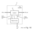
- the CO2 removal system 4 includes a CO2 capture system 10 that is configured to remove CO2 from the flue gas stream FG before emitting the cleaned flue gas stream to an exhaust stack 7 (or alternatively additional processing). It is also configured to output CO2 removed from the flue gas stream FG. Details of CO2 removal system 4 are generally depicted in FIG. 1B .
- CO2 removal system 4 includes a capture system 10 for capturing and removing CO2 from a flue gas stream FG and a regeneration system 11 for regenerating ionic solution used to remove CO2 from the flue gas stream FG. Details of capture system 10 are generally depicted in FIG. 1C .
- a capture system 10 of a CO2 removal system 4 is generally depicted.
- the capture system 10 is a chilled ammonia based CO2 capture system.
- a CO2 absorber is provided in which an absorbent ionic ammonia solution (ionic solution) is contacted with a flue gas stream (FG) containing CO2.
- ionic ammonia solution also referred to herein simply as "ionic solution”
- ionic solution is typically aqueous and may be composed of, for example, water, ammonia, carbon dioxide and derivatives thereof.
- Examples of derivatives of ammonia and carbon dioxide that may be present in the ionic solution include ammonium ions, bicarbonate ions, carbonate ions, and/or carbamate ions.
- An example of a known chilled ammonia based CO2 removal system is described in WO 2006/022885 .
- a CO2 absorber 15 is configured to receive a flue gas stream (FG) originating from, for example, the combustion chamber of a fossil fuel fired boiler 5 (see FIG. 1A ). It is also configured to receive a lean ionic solution supply from regenerator 11 (see FIG. 1B ). The lean ionic solution is introduced into the CO2 absorber 15 via a liquid distribution system 16a while the flue gas stream FG is also received by the CO2 absorber 15 via flue gas inlet 17.
- FG flue gas stream
- regenerator 11 see FIG. 1B
- the ionic solution is put into contact with the flue gas stream via a gas-liquid contacting device (hereinafter, mass transfer device, MTD) 18 used for mass transfer and located in the CO2 absorber 15 and within the path that the flue gas stream travels from its entrance via inlet 17 to the CO2 absorber exit 19.
- MTD 18 may be, for example, one or more commonly known structured or random packing materials, or a combination thereof.
- the ionic solution acts to absorb CO2 from the flue gas stream, thus making the ionic solution "rich” with CO2 (rich solution).
- the rich ionic solution continues to flow downward through the MTD 18 and is then collected in the bottom 20 of the CO2 absorber 15.
- the CO2 removal system 4 may optionally comprise a rich solution buffer tank (not shown) in liquid connection with the CO2 absorber 15 and configured to receive rich solution from the CO2 absorber.
- Rich solution collected in the CO2 absorber 15 may be cooled and directly recycled via a liquid conduit 21 and a liquid distribution system 16b to the top of the CO2 absorber 15 for use in capturing further CO2 from a gas stream, resulting in a rich ionic solution having a higher concentration of absorbed CO2. At least a portion of the rich solution collected in the CO2 absorber is sent to a regeneration system 11 for regeneration.
- the ionic solution is treated to release the CO2 absorbed from the flue gas stream.
- the CO2 released from the ionic solution may then be output to storage or other predetermined uses/purposes.
- the ionic solution is said to be "lean”.
- the lean ionic solution is then again ready to absorb CO2 from a flue gas stream and may be directed back to the liquid distribution system 16 whereby it is again introduced into the CO2 absorber 15.
- the CO2 removal system 4 may optionally comprise a lean solution buffer tank (not shown) in liquid connection with the regenerator system 11 and configured to receive lean solution from the regenerator system.
- System 11 includes a regenerator 25.
- Regenerator 25 is configured to receive a rich solution feed from the capture system 10 and to return a lean solution feed to the capture system 10 once CO2 has been separated from the rich solution.
- the separated CO2 leaves the regenerator via a gas exit 26.
- the regenerator may further comprise a mass transfer device (MTD) 28 which facilitates heat and mass transfer between the rich solution which is fed to the regenerator and the vapor produced in the regenerator, e.g. by means of a re-boiler 27.
- MTD mass transfer device
- the rich ionic solution is pressurized and heated so that CO2 contained in the solution separates from the ionic solution.
- the regeneration process generally comprises raising the pressure in the regenerator 25 to in the range of 2-150 bar, preferably 10-30 bar, and raising the temperature of the ionic solution to in the range of 50-200 °C, preferably 100-150 °C. Under these conditions, nearly all of the CO2 absorbed CO2 is released from the ionic solution into the gas phase.
- the gas phase may also comprise a minor portion of NH3 (ammonia slip) which may be condensed and returned to the capture system 10 for use in capturing further CO2 from a gas stream. Lean ionic solution is collected in the bottom of the regenerator.
- a heat exchanger 30 may be configured to heat the rich ionic solution coming from the CO2 absorber 15 using hot lean ionic solution coming from the regenerator 25.
- the CO2 removal system 4 generally comprises a first liquid conduit 12 configured to forward CO2 rich ionic solution from the CO2 absorber 10 to the regenerator 11.
- the conduit 12 may for example comprise a pipe connecting a rich solution outlet on the CO2 absorber 10 to a liquid inlet of the regenerator.
- the first liquid conduit 12 may for example comprise a pump implemented to forward the ionic solution.
- the first liquid conduit 12 may comprise a high pressure pump implemented to forward the ionic solution into the regenerator, and to increase the pressure inside the regenerator to a predetermined value, for example in the range of 10-30 bar.
- the first liquid conduit 12 may further comprise a rich solution buffer tank (not shown) configured to hold a volume of ionic solution.
- the first liquid conduit 12 may be configured to forward a first portion of rich ionic solution from the CO2 absorber to the regenerator, while a second portion of the rich ionic solution is directly forwarded to the liquid distribution system of the CO2 absorber to absorb more CO2 before being sent to the regenerator.
- the CO2 removal system 4 generally comprises a second liquid conduit 13 configured to forward CO2 lean ionic solution from the regenerator 11 to the CO2 absorber 10.
- the conduit 13 may for example comprise a pipe connecting a lean solution outlet on the regenerator 11 to a liquid distribution system 16 of the CO2 absorber.
- the second liquid conduit 13 may for example comprise a pump implemented to forward the ionic solution.
- the first liquid conduit 13 may also comprise one or more heat exchangers or cooling devices configured to reduce the temperature of the ionic solution, for example to a temperature in the range of 0-20 °C, before it is introduced into the CO2 absorber 10.
- the second liquid conduit 13 may further comprise a lean solution buffer tank (not shown) configured to hold a volume of ionic solution.
- water will typically accumulate in the ionic solution circulating between the capture system 10 and regeneration system 11. This accumulation of water is a consequence of the differences in water (moisture) content between the gas streams fed to the CO2 removal system 4, and the gas streams leaving the CO2 removal system 4. Moisture present in the feed gas stream will typically precipitate in the low temperature absorption process in the CO2 absorber 15. This accumulated water acts to dilute the ionic solution circulating between the capture system 10 and regeneration system 11, thereby reducing the ability of the ionic solution to "capture" CO2 from a flue gas stream.
- the amount of water in the circulating ionic solution has been adjusted by, e.g., removing a portion of the ionic solution in a "bleed stream” and by compensating the dilution of the ionic solution by adding fresh ammonia.
- the ionic solution in the "bleed stream” must then be disposed of and fresh NH3 must be provided, which leads to increased costs.
- the CO2 removal system 4 is provided with a gas-liquid separating device 40 configured to remove water from the circulating ionic solution, while avoiding loss of ammonia and derivatives thereof from the CO2 removal system 4.
- the CO2 removal system 4 comprises a gas-liquid separating device 40 arranged in fluid connection with, and configured to receive a portion of, the circulating ionic solution stream, separate the received ionic solution into an NH3 rich gas phase and an NH3 lean liquid phase, and reintroduce the NH3 rich gas phase into the circulating ionic solution stream.
- the NH3 lean liquid phase consisting mainly of water, is removed from the system.
- Ionic solution may be supplied to the gas-liquid separating device 40 passively, e.g. by means of the internal pressure of the CO2 removal system, or actively, e.g. by means of a pump.
- the gas-liquid separating device 40 comprises a stripper 41.
- the stripper 41 may be configured as, for example, a generally cylindrical shaped steel vessel configured to operate within a pre-determined pressure range.
- the stripper 41 is preferably equipped with one or more suitable mass transfer devices (MTD) 42.
- MTD mass transfer devices
- the MTD may be, for example, valve trays, sieve trays, structured packing, random packing or other suitable packing materials, or a combination thereof.
- a heating system/device 43 may be provided in the stripper 41 for heating the ionic solution received by the stripper.
- the stripper 41 is preferably configured to provide sufficient heat to the ionic solution that low boiling point components, for example NH3 and CO2, are transferred to a gas phase, while high boiling point components, for example water, are collected in a liquid phase at the bottom of the stripper.
- the ionic solution may be heated up appropriately via, for example, a re-boiler.
- the re-boiler may be heated using, for example, electrically generated heat or steam or other hot fluids fed from another part of the CO2 removal system 4, e.g. hot flue gas or hot lean solution.
- the re-boiler may be heated via steam fed from a source external to the CO2 removal system 4, such as, for example some source within the power generation system 6 or flue gas cleaning system 1.
- the heat may be supplied by any heating means capable of providing heat at a temperature above the boiling temperature of water at the operating pressure of the stripper. Since the stripper is generally relatively small in size, it can be heated by any of a number of different methods, including steam in a re-boiler as described above, but also by life steam injection (i.e. injection of steam directly into the bottom of the stripper), by electricity, or by other hot media, such as hot flue gases or hot condensate. If the stripper is heated by life steam injection, the condensed water from the injected steam will be collected together with the liquid phase at the bottom of the stripper. Life steam injection is efficient and saves the re-boiler.
- the stripper 41 is configured to discharge the gas phase, containing mainly NH3 and CO2, via a gas exit 44, and the liquid phase, containing mainly water, via a liquid exit 45.
- the stripper may be arranged to produce a liquid phase at the bottom of the stripper 46 containing less than 5 % NH3 by weight, such as less than 4 %, 3 %, 2 % or 1 % NH3.
- the stripper 41 may be arranged to produce a liquid phase at the bottom of the stripper 46 consisting of essentially pure water.
- the liquid phase collected at the bottom of the stripper 46 generally has a temperature in the range of about or slightly below the boiling temperature of water at the relevant pressure, e.g. about 80-100 °C at atmospheric pressure.
- a heat exchanger 47 may be provided to transfer heat from the liquid phase removed from the bottom of the stripper 46 to the ionic solution received from the circulating ionic solution stream (and thereby raise the temperature of the ionic solution to a predetermined temperature, for example, between 80-100 °C) before it is introduced into the stripper 41.
- the portion of ionic solution which is received from the circulating ionic solution may vary within a wide range depending on the need for water removal in a specific CO2 removal system.
- a suitable portion may be calculated based on, e.g., the water accumulation in a specific CO2 removal system.
- the portion may also be variable in a system such that variations in, e.g., the moisture content of the incoming gas stream may be compensated.
- the portion may for example comprise in a range of 0.01-25 %, such as in a range of 0.01-10 % or 0.01-5 %, of the total mass flow rate of the circulating ionic solution.
- the portion of ionic solution which is received may be in a range of 0.05-1 % of the total mass flow rate of the circulating ionic solution.
- the gas-liquid separating device 40 is arranged in fluid connection with the circulating ionic solution stream of the CO2 removal system.
- the fluid connection may preferably include at least one fluid connection 48 configured to direct a portion of the circulating ionic solution stream to a liquid inlet of the gas-liquid separating device 40.
- the fluid connection may comprise a pump and a flow regulating device operable for regulating the amount of ionic solution which is fed to the gas-liquid separating device 40.
- the fluid connection may preferably include at least one fluid connection 49 configured to feed the gas phase produced in the gas-liquid separating device 40 from a gas outlet 44 of the gas-liquid separating device 40 into the circulating ionic solution stream of the CO2 removal system 4.
- the gas-liquid separating device 40 may preferably include at least one fluid connection 50 configured to remove the liquid phase produced in the gas-liquid separating device 40 via a liquid outlet 45.
- ionic solution for the gas-liquid separating device 40 may be received from, and reintroduced into, any position along the ionic solution circulation.
- positions along the ionic solution circulation where ionic solution may be received and/or reintroduced include the CO2 absorber 10, the regenerator 11, the first liquid conduit 12 configured to forward CO2 rich ionic solution from the CO2 absorber to the regenerator, and the second liquid conduit 13 configured to forward CO2 lean ionic solution from the regenerator to the CO2 absorber.
- the ionic solution for the gas-liquid separating device 40 may be received from a CO2 rich portion of the circulating ionic solution stream, for example from the ionic solution collected at the bottom of the CO2 absorber or from the first liquid conduit configured to forward CO2 rich ionic solution from the CO2 absorber to the regenerator.
- An advantage of this embodiment is that the rich solution is generally provided at a pressure close to atmospheric pressure, for example at a pressure of less than 2 bar. This means that the gas-liquid separating device 40 and fluid connections 48, 49 do not need to be configured for operation at high pressure. Compared to an embodiment wherein the ionic solution is received at high pressure, it also means that the heat required in order to separate the ionic solution into a liquid phase and a gas phase may be provided at a lower temperature. Therefore, in an embodiment wherein the ionic solution is received at a pressure close to atmospheric pressure, the gas-liquid separating device 40 may for example use low pressure steam or electrical heating for heating the ionic solution in order to separate the ionic solution into a liquid phase and a gas phase.
- the ionic solution for the gas-liquid separating device 40 may be received from a CO2 lean portion of the circulating ionic solution stream, for example from the ionic solution collected at the bottom 29 of the regenerator 25 or from the liquid conduit 13 configured to forward CO2 lean ionic solution from the regenerator to the CO2 absorber 15.
- An advantage of this embodiment is that the lean solution is generally provided at a high temperature, such as a temperature in the range of 50-200 °C, since it has undergone heating in the regenerator 25. This means that a relatively low amount of additional heat may be required in order to separate the ionic solution into a liquid phase and a gas phase.
- the heat may for example be provided by medium pressure steam or by electrical heating.
- the gas phase produced by the gas-liquid separating device 40 may be reintroduced into the regenerator or into a liquid conduit configured to forward a solution stream to the regenerator.
- An advantage of this embodiment is that heat transferred to the gas phase in the gas-liquid separating device 40 is used to indirectly reduce the heating requirement of the regenerator 25. In other words, the energy requirement of the gas-liquid separating device 40 may replace a portion of the energy requirement of the regenerator 25. Accordingly, in this embodiment the operation of the gas-liquid separating device 40 can be made essentially energy neutral.
- a CO2 removal system 4 as described above is proposed that includes a gas-liquid separating device 40 which comprises a stripper 41 configured to remove water from the circulating ionic solution by stripping as described in detail above.
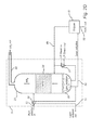
- FIG. 2C is a schematic illustration of an embodiment wherein the received ionic solution is rich ionic solution from the bottom 20 of the CO2 absorber 15 and wherein the gas phase is reintroduced into the regenerator 25.
- the gas-liquid separating device 40 comprises a stripper 41.
- the stripper 41 may be configured as, for example, a generally cylindrical shaped steel vessel configured to operate within a pressure range of about 1-5 bar.
- the stripper 41 is preferably equipped with one or more suitable mass transfer devices (MTD) 42.
- the MTD may be, for example, valve trays, sieve trays, structured packing, random packing or other suitable packing materials, or a combination thereof.
- a heating system/device 43 may be provided in the stripper 41 for heating the ionic solution received by the stripper.
- the heating system could be heated by low pressure steam (typically with a pressure in the range of 4-8 bar), or, if the amount of heat required is too low to justify the infrastructure for low pressure steam, via electrical heating devices/systems.
- the stripper 41 is preferably configured to provide sufficient heat to the ionic solution so that, at a pressure in the range of 1-5 bar, low boiling point components, for example NH3 and CO2, are transferred to a gas phase, while high boiling point components, for example water, are collected in a liquid phase at the bottom 46 of the stripper 41.
- the stripper 41 is configured to discharge the gas phase, containing mainly NH3 and CO2, via a gas exit 44, and the liquid phase, containing mainly water, via a liquid exit 45.
- the stripper 41 is configured to receive lean ionic solution collected at the bottom of the CO2 absorber 15.
- the rate at which lean ionic solution from the CO2 absorber 15 is fed (feed rate) to the stripper 41 is, for example, approximately 0.5% to 2.0% of the feed rate at which rich ionic solution is fed to the CO2 absorber 15.
- the ionic solution received from the CO2 absorber 15 is contacted via a liquid/gas MTD 42, preferably in a countercurrent flow, with upcoming vapors fed to or generated in the bottom of the stripper 41.
- the liquid phase collected at the bottom 20 of the CO2 absorber 15 generally has a temperature in the range of 10-30 °C.
- the liquid phase collected at the bottom 46 of the stripper 41 generally has a temperature in the range of 80-100 °C.
- a heat exchanger 47 may be provided to transfer heat from the liquid phase removed from the bottom of the stripper 41 to the ionic solution received from the CO2 absorber 15 (and thereby raise the temperature of the ionic solution to a predetermined temperature, for example, between 50-80 °C) before it is introduced into the stripper 41.
- the gas phase (CO2, NH3, residual water vapor) from the stripper 41 is sent back, either in part or completely, to the regenerator 25.
- the liquid phase collected at the bottom 46 of the stripper 41 will preferably be water or an aqueous solution low in NH3 and with no CO2.
- the water may be sent to a wash water stripper or directly to battery limits (BL).
- the invested heat is substantially, if not completely, recovered in the regenerator vessel 25 and/or in the small feed/effluent heat exchanger 47.
- FIG. 2D is a schematic illustration of an embodiment wherein the received ionic solution is lean ionic solution from the bottom 29 of the regenerator 25 and wherein the formed gas phase is reintroduced into the regenerator 25.
- the gas-liquid separating device 40 comprises a stripper 41.
- the stripper 41 may be configured as, for example, a generally cylindrical shaped steel vessel configured to operate within a pressure range of about 10-30 bar.
- the stripper 41 is preferably equipped with one or more suitable mass transfer devices (MTD) 42.
- the MTD may be, for example, valve trays, sieve trays, structured packing, random packing or other suitable packing materials, or a combination thereof.
- a heating system/device 43 may be provided in the stripper 41 for heating the ionic solution received by the stripper.
- the heating system could be heated by medium pressure steam (typically with a pressure in the range of 10-30 bar), or, if the amount of heat required is too low to justify the infrastructure for medium pressure steam, via electrical heating devices/systems.
- the stripper 41 is preferably configured to provide sufficient heat to the ionic solution so that, at a pressure in the range of 10-30 bar, low boiling point components, for example NH3 and CO2, are transferred to a gas phase, while high boiling point components, for example water, are collected in a liquid phase at the bottom of the stripper.
- the stripper 41 is configured to discharge the gas phase, containing mainly NH3 and CO2, via a gas exit 44, and the liquid phase, containing mainly water, via a liquid exit 45.
- the stripper 41 is configured to receive lean ionic solution from the regenerator 25.
- the rate at which lean ionic solution from the regenerator 25 is fed (feed rate) to the stripper 41 is, for example, approximately 0.5% to 2.0% of the feed rate at which rich ionic solution is fed to the regenerator 25.
- the ionic solution received from the regenerator 25 is contacted via a liquid/gas MTD 42, preferably in a countercurrent flow, with upcoming vapors (upcoming vapors should be sufficient) fed to or generated in the bottom 46 of the stripper vessel 41.
- the liquid phase collected at the bottom 29 of the regenerator 25 generally has a temperature in the range of 100-150 °C.
- the liquid phase collected at the bottom 46 of the stripper 41 generally has a temperature in the range of 150-250 °C.
- a heat exchanger 47 may be provided to transfer heat from the liquid phase removed from the bottom of the stripper 41 to the ionic solution received from the regenerator 25 (and thereby raise the temperature of the ionic solution to a predetermined temperature, for example, between 150-200 °C) before it is introduced into the stripper 41.
- the gas phase (CO2, NH3, residual water vapor) from the stripper 41 is sent back, either in part or completely, to the regenerator 25.
- the liquid phase collected at the bottom 46 of the stripper 41 will preferably be water or an aqueous solution low in NH3 and with no CO2.
- the water may be sent to a wash water stripper or directly to battery limits (BL).
- the invested heat is substantially, if not completely, recovered in the regenerator vessel 25 and/or in the small feed/effluent heat exchanger 47.
- the heating requirement of the regenerator generally provided for by low pressure (4-8 bar) steam, could thus be reduced.
- the CO2 removal system may, optionally, further comprise a water wash system operative for removing trace amounts of NH3 present in the gas stream leaving the CO2 absorber.
- a water wash system is schematically illustrated in FIG. 3 .
- the water wash system 60 generally comprises an absorber 61 (referred to herein as the NH3 absorber) and a stripper 62 (referred to herein as the NH3 stripper).
- a stream of water or an aqueous solution having a concentration of NH3 of less than 5 % by weight is circulated between the NH3 absorber 61 and the NH3 stripper 62.
- a gas stream depleted in CO2 from the CO2 absorber 15 is brought into contact with the stream of water or an aqueous solution having a concentration of NH3 of less than 5 % by weight such that NH3 is absorbed in said stream of water or aqueous solution.
- At least a portion of the water or aqueous solution used in the NH3 absorber is withdrawn and fed to the NH3 stripper 62.
- a gaseous phase comprising NH3 is separated from the water or aqueous solution and removed from the water wash system.
- the gaseous phase from the NH3 stripper 62 may also contain water vapor, CO2 and other low-boiling contaminants.
- the separated gaseous phase comprising NH3 may be returned to the ionic solution of the CO2 removal system, e.g. to the regenerator 25, to minimize the loss of NH3 from the system.
- the water or aqueous solution from which NH3 has been separated is recycled to the NH3 absorber 61 for use in capturing further NH3 from a gas stream.
- the CO2 removal system 4 may further comprise a water wash system 60 operative for removing trace amounts of NH3 present in the gas stream leaving the CO2 absorber.
- the stripper 41 may be integrated with the water wash system 60, such that an NH3 rich stream from the water wash system may be directed to the stripper 41 and an NH3 lean stream from the stripper 41 may be directed to the water wash system 60.
- the liquid phase collected at the bottom of the stripper 41 i.e. water or an aqueous solution low in NH3 and with no CO2, may be forwarded, either in part or completely, to the water wash system 60 for use in absorbing NH3 from the gas stream.
- the stripper may be further configured to receive other small ammonia rich streams that are generated by the CO2 removal system.
- the stripper 41 can be further configured to receive the reflux from the water wash stripper 62. This arrangement provides the further advantage of a suitable destination for recycling NH3 which has left the circulating stream of ionic solution via the treated gas stream.
- the water wash system 60 comprises a condenser 63 configured to receive the gas stream produced by the water wash stripper 62, and condense water vapor contained therein.
- the aqueous condensate, also containing NH3, collected in the condenser 63 is forwarded to the top of the stripper 41 together with the ionic solution coming from the circulating ionic solution.
- the water may be recovered as pure water at the bottom of the stripper 41 and the ammonia and CO2 contained in the condensate may be recycled to the regenerator 25.
- the use of the stripper 41 provides the advantages of:
Landscapes
- Chemical & Material Sciences (AREA)
- Engineering & Computer Science (AREA)
- General Chemical & Material Sciences (AREA)
- Health & Medical Sciences (AREA)
- Biomedical Technology (AREA)
- Environmental & Geological Engineering (AREA)
- Chemical Kinetics & Catalysis (AREA)
- Oil, Petroleum & Natural Gas (AREA)
- Analytical Chemistry (AREA)
- Sustainable Development (AREA)
- Life Sciences & Earth Sciences (AREA)
- Gas Separation By Absorption (AREA)
- Treating Waste Gases (AREA)
- Physical Water Treatments (AREA)
Priority Applications (7)
| Application Number | Priority Date | Filing Date | Title |
|---|---|---|---|
| PCT/IB2010/000525 WO2010103392A1 (en) | 2009-03-12 | 2010-03-11 | Flue gas treatment system and the method using amonia solution |
| BRPI1008953A BRPI1008953A2 (pt) | 2009-03-12 | 2010-03-11 | sistema de tratamento de gás de combustão e o método usando solução de amônia. |
| RU2011141273/05A RU2011141273A (ru) | 2009-03-12 | 2010-03-11 | Система и способ очистки топочного газа с использованием раствора аммиака |
| MX2011009370A MX2011009370A (es) | 2009-03-12 | 2010-03-11 | Sistema de tratamiento de gas de combustion y el metodo que utiliza solucion de amoniaco. |
| MA34238A MA33187B1 (fr) | 2009-03-12 | 2010-03-11 | Système de traitement de gaz d'évacuation et procédé utilisant une solution d'ammoniaque |
| IL214569A IL214569A0 (en) | 2009-03-12 | 2011-08-09 | Flue gas treatment system and the method using ammonia solution |
| ZA2011/06359A ZA201106359B (en) | 2009-03-12 | 2011-08-30 | Flue gas treatment system and the method using amonia solution |
Applications Claiming Priority (1)
| Application Number | Priority Date | Filing Date | Title |
|---|---|---|---|
| US15965809P | 2009-03-12 | 2009-03-12 |
Publications (2)
| Publication Number | Publication Date |
|---|---|
| EP2230000A1 true EP2230000A1 (de) | 2010-09-22 |
| EP2230000B1 EP2230000B1 (de) | 2013-06-19 |
Family
ID=42237261
Family Applications (1)
| Application Number | Title | Priority Date | Filing Date |
|---|---|---|---|
| EP09179658.1A Active EP2230000B1 (de) | 2009-03-12 | 2009-12-17 | Vorrichtung und Verfahren zur Abgasbehandlung mit Ammoniaklösung |
Country Status (9)
| Country | Link |
|---|---|
| EP (1) | EP2230000B1 (de) |
| BR (1) | BRPI1008953A2 (de) |
| DK (1) | DK2230000T3 (de) |
| IL (1) | IL214569A0 (de) |
| MA (1) | MA33187B1 (de) |
| MX (1) | MX2011009370A (de) |
| RU (1) | RU2011141273A (de) |
| WO (1) | WO2010103392A1 (de) |
| ZA (1) | ZA201106359B (de) |
Cited By (7)
| Publication number | Priority date | Publication date | Assignee | Title |
|---|---|---|---|---|
| WO2012036946A3 (en) * | 2010-09-14 | 2012-05-03 | Alstom Technology Ltd | Removal of non-volatiles from ammonia - based c02 -absorbent solution |
| WO2013072821A1 (en) * | 2011-11-17 | 2013-05-23 | Alstom Technology Ltd | Low pressure stripping in a gas purification process and systems thereof |
| WO2013144899A3 (en) * | 2012-03-30 | 2014-01-23 | Alstom Technology Ltd | Flue gas treatment system with ammonia solvent for capture of carbon dioxide |
| EP2754481A1 (de) * | 2013-01-11 | 2014-07-16 | Alstom Technology Ltd | Wärmeintegration eines Verfahrens mit gekühltem Ammoniak |
| EP2768601A1 (de) * | 2011-09-26 | 2014-08-27 | EIG Inc. | Hocheffiziente gleichzeitigen abscheidung von co2 und h2s aus druckgas |
| US8864879B2 (en) | 2012-03-30 | 2014-10-21 | Jalal Askander | System for recovery of ammonia from lean solution in a chilled ammonia process utilizing residual flue gas |
| EP3674261A1 (de) | 2018-12-27 | 2020-07-01 | GasConTec GmbH | Verfahren zur synthese einer wasserstoffhaltigen verbindung |
Families Citing this family (2)
| Publication number | Priority date | Publication date | Assignee | Title |
|---|---|---|---|---|
| CN104803465A (zh) * | 2015-04-07 | 2015-07-29 | 山西大学 | 利用烟道气降低碱性含氨污水pH值的装置和方法 |
| CN115754146B (zh) * | 2022-11-17 | 2024-04-30 | 南方电网电力科技股份有限公司 | 一种活性炭吸附降解的评价试验台 |
Citations (4)
| Publication number | Priority date | Publication date | Assignee | Title |
|---|---|---|---|---|
| US3225519A (en) | 1962-12-13 | 1965-12-28 | Hydrocarbon Research Inc | Gas absorption |
| EP0077492A2 (de) | 1981-10-21 | 1983-04-27 | Linde Aktiengesellschaft | Verfahren und Vorrichtung zum Regulieren des NH3-Gehaltes in der Waschflüssigkeit einer Gaswäsche |
| WO2002089958A2 (de) | 2001-05-09 | 2002-11-14 | Thyssen Krupp Encoke Gmbh | Verfahren zur reinigung von kokereigas |
| US20080307968A1 (en) | 2007-06-04 | 2008-12-18 | Posco | Apparatus and Method for Recovering Carbon Dioxide from Flue Gas Using Ammonia Water |
Family Cites Families (1)
| Publication number | Priority date | Publication date | Assignee | Title |
|---|---|---|---|---|
| RU2378040C2 (ru) | 2004-08-06 | 2010-01-10 | ИАйДжи, ИНК. | Тщательная очистка газообразных продуктов сгорания, включая удаление co2 |
-
2009
- 2009-12-17 EP EP09179658.1A patent/EP2230000B1/de active Active
- 2009-12-17 DK DK09179658.1T patent/DK2230000T3/da active
-
2010
- 2010-03-11 MA MA34238A patent/MA33187B1/fr unknown
- 2010-03-11 WO PCT/IB2010/000525 patent/WO2010103392A1/en active Application Filing
- 2010-03-11 RU RU2011141273/05A patent/RU2011141273A/ru not_active Application Discontinuation
- 2010-03-11 BR BRPI1008953A patent/BRPI1008953A2/pt not_active IP Right Cessation
- 2010-03-11 MX MX2011009370A patent/MX2011009370A/es not_active Application Discontinuation
-
2011
- 2011-08-09 IL IL214569A patent/IL214569A0/en unknown
- 2011-08-30 ZA ZA2011/06359A patent/ZA201106359B/en unknown
Patent Citations (4)
| Publication number | Priority date | Publication date | Assignee | Title |
|---|---|---|---|---|
| US3225519A (en) | 1962-12-13 | 1965-12-28 | Hydrocarbon Research Inc | Gas absorption |
| EP0077492A2 (de) | 1981-10-21 | 1983-04-27 | Linde Aktiengesellschaft | Verfahren und Vorrichtung zum Regulieren des NH3-Gehaltes in der Waschflüssigkeit einer Gaswäsche |
| WO2002089958A2 (de) | 2001-05-09 | 2002-11-14 | Thyssen Krupp Encoke Gmbh | Verfahren zur reinigung von kokereigas |
| US20080307968A1 (en) | 2007-06-04 | 2008-12-18 | Posco | Apparatus and Method for Recovering Carbon Dioxide from Flue Gas Using Ammonia Water |
Cited By (15)
| Publication number | Priority date | Publication date | Assignee | Title |
|---|---|---|---|---|
| WO2012036946A3 (en) * | 2010-09-14 | 2012-05-03 | Alstom Technology Ltd | Removal of non-volatiles from ammonia - based c02 -absorbent solution |
| EP3192581A1 (de) * | 2010-09-14 | 2017-07-19 | General Electric Technology GmbH | Entfernung von schwerflüchtigen substanzen aus ammoniakbasierter co2-absorberlösung |
| EP3184162A1 (de) * | 2010-09-14 | 2017-06-28 | General Electric Technology GmbH | Entfernung von schwerflüchtigen substanzen aus ammoniakbasierter co2-absorberlösung |
| US8623307B2 (en) | 2010-09-14 | 2014-01-07 | Alstom Technology Ltd. | Process gas treatment system |
| EP2768601A4 (de) * | 2011-09-26 | 2015-04-08 | Eig Inc | Hocheffiziente gleichzeitigen abscheidung von co2 und h2s aus druckgas |
| EP2768601A1 (de) * | 2011-09-26 | 2014-08-27 | EIG Inc. | Hocheffiziente gleichzeitigen abscheidung von co2 und h2s aus druckgas |
| US9463416B2 (en) | 2011-09-26 | 2016-10-11 | Eig, Inc. | Simultaneous high efficiency capture of CO2 and H2S from pressurized gas |
| US8690992B2 (en) | 2011-11-17 | 2014-04-08 | Alstom Technology Ltd | Low pressure stripping in a gas purification process and systems thereof |
| US8470077B2 (en) | 2011-11-17 | 2013-06-25 | Alstom Technology Ltd | Low pressure stripping in a gas purification process and systems thereof |
| WO2013072821A1 (en) * | 2011-11-17 | 2013-05-23 | Alstom Technology Ltd | Low pressure stripping in a gas purification process and systems thereof |
| US8864879B2 (en) | 2012-03-30 | 2014-10-21 | Jalal Askander | System for recovery of ammonia from lean solution in a chilled ammonia process utilizing residual flue gas |
| WO2013144899A3 (en) * | 2012-03-30 | 2014-01-23 | Alstom Technology Ltd | Flue gas treatment system with ammonia solvent for capture of carbon dioxide |
| EP2754481A1 (de) * | 2013-01-11 | 2014-07-16 | Alstom Technology Ltd | Wärmeintegration eines Verfahrens mit gekühltem Ammoniak |
| EP3674261A1 (de) | 2018-12-27 | 2020-07-01 | GasConTec GmbH | Verfahren zur synthese einer wasserstoffhaltigen verbindung |
| WO2020136014A1 (de) | 2018-12-27 | 2020-07-02 | Gascontec Gmbh | Verfahren zur synthese einer wasserstoffhaltigen verbindung |
Also Published As
| Publication number | Publication date |
|---|---|
| ZA201106359B (en) | 2012-12-27 |
| RU2011141273A (ru) | 2013-04-20 |
| MX2011009370A (es) | 2011-10-03 |
| MA33187B1 (fr) | 2012-04-02 |
| EP2230000B1 (de) | 2013-06-19 |
| DK2230000T3 (da) | 2013-09-08 |
| WO2010103392A1 (en) | 2010-09-16 |
| BRPI1008953A2 (pt) | 2016-03-15 |
| IL214569A0 (en) | 2011-09-27 |
Similar Documents
| Publication | Publication Date | Title |
|---|---|---|
| EP2230000B1 (de) | Vorrichtung und Verfahren zur Abgasbehandlung mit Ammoniaklösung | |
| EP2722097B1 (de) | System zur verarbeitung von verbrennungsabgasen und verfahren zur verarbeitung von verbrennungsabgasen | |
| JP5859076B2 (ja) | アンモニアベースのco2吸収性溶液からの不揮発物の除去 | |
| US9138677B2 (en) | Ammonia stripper for a carbon capture system for reduction of energy consumption | |
| WO2012153812A1 (ja) | Co2回収装置およびco2回収方法 | |
| WO2010122830A1 (ja) | Co2回収装置及びco2回収方法 | |
| WO2013039041A1 (ja) | Co2回収装置およびco2回収方法 | |
| EP2883594B1 (de) | Co2-rückgewinnungsvorrichtung und co2-rückgewinnungsverfahren | |
| KR20130023484A (ko) | 에너지 효율이 증대된 발전소 이산화탄소 포집장치 및 포집방법 | |
| EP2609987A1 (de) | Entladungsgas-behandlungssystem mit einer vorrichtung für co2-abbau | |
| JP5738137B2 (ja) | Co2回収装置およびco2回収方法 | |
| US10213728B2 (en) | Method for separating carbon dioxide from a gas flow, in particular from a flue gas flow, and separating device for separating carbon dioxide from a gas flow, in particular from a flue gas flow | |
| JP5881498B2 (ja) | 窒素酸化物および硫黄酸化物除去システム、窒素酸化物および硫黄酸化物除去方法、および二酸化炭素回収システム |
Legal Events
| Date | Code | Title | Description |
|---|---|---|---|
| PUAI | Public reference made under article 153(3) epc to a published international application that has entered the european phase |
Free format text: ORIGINAL CODE: 0009012 |
|
| AK | Designated contracting states |
Kind code of ref document: A1 Designated state(s): AT BE BG CH CY CZ DE DK EE ES FI FR GB GR HR HU IE IS IT LI LT LU LV MC MK MT NL NO PL PT RO SE SI SK SM TR |
|
| AX | Request for extension of the european patent |
Extension state: AL BA RS |
|
| 17P | Request for examination filed |
Effective date: 20110322 |
|
| 17Q | First examination report despatched |
Effective date: 20110805 |
|
| RIC1 | Information provided on ipc code assigned before grant |
Ipc: B01D 53/96 20060101ALI20120925BHEP Ipc: B01D 53/62 20060101AFI20120925BHEP |
|
| GRAP | Despatch of communication of intention to grant a patent |
Free format text: ORIGINAL CODE: EPIDOSNIGR1 |
|
| GRAS | Grant fee paid |
Free format text: ORIGINAL CODE: EPIDOSNIGR3 |
|
| GRAA | (expected) grant |
Free format text: ORIGINAL CODE: 0009210 |
|
| AK | Designated contracting states |
Kind code of ref document: B1 Designated state(s): AT BE BG CH CY CZ DE DK EE ES FI FR GB GR HR HU IE IS IT LI LT LU LV MC MK MT NL NO PL PT RO SE SI SK SM TR |
|
| REG | Reference to a national code |
Ref country code: GB Ref legal event code: FG4D |
|
| REG | Reference to a national code |
Ref country code: CH Ref legal event code: EP |
|
| REG | Reference to a national code |
Ref country code: AT Ref legal event code: REF Ref document number: 617314 Country of ref document: AT Kind code of ref document: T Effective date: 20130715 |
|
| REG | Reference to a national code |
Ref country code: IE Ref legal event code: FG4D |
|
| REG | Reference to a national code |
Ref country code: DE Ref legal event code: R096 Ref document number: 602009016494 Country of ref document: DE Effective date: 20130814 |
|
| REG | Reference to a national code |
Ref country code: DK Ref legal event code: T3 |
|
| REG | Reference to a national code |
Ref country code: NL Ref legal event code: T3 |
|
| REG | Reference to a national code |
Ref country code: NO Ref legal event code: T2 Effective date: 20130619 |
|
| PG25 | Lapsed in a contracting state [announced via postgrant information from national office to epo] |
Ref country code: ES Free format text: LAPSE BECAUSE OF FAILURE TO SUBMIT A TRANSLATION OF THE DESCRIPTION OR TO PAY THE FEE WITHIN THE PRESCRIBED TIME-LIMIT Effective date: 20130930 Ref country code: SI Free format text: LAPSE BECAUSE OF FAILURE TO SUBMIT A TRANSLATION OF THE DESCRIPTION OR TO PAY THE FEE WITHIN THE PRESCRIBED TIME-LIMIT Effective date: 20130619 Ref country code: GR Free format text: LAPSE BECAUSE OF FAILURE TO SUBMIT A TRANSLATION OF THE DESCRIPTION OR TO PAY THE FEE WITHIN THE PRESCRIBED TIME-LIMIT Effective date: 20130920 Ref country code: LT Free format text: LAPSE BECAUSE OF FAILURE TO SUBMIT A TRANSLATION OF THE DESCRIPTION OR TO PAY THE FEE WITHIN THE PRESCRIBED TIME-LIMIT Effective date: 20130619 Ref country code: SE Free format text: LAPSE BECAUSE OF FAILURE TO SUBMIT A TRANSLATION OF THE DESCRIPTION OR TO PAY THE FEE WITHIN THE PRESCRIBED TIME-LIMIT Effective date: 20130619 Ref country code: FI Free format text: LAPSE BECAUSE OF FAILURE TO SUBMIT A TRANSLATION OF THE DESCRIPTION OR TO PAY THE FEE WITHIN THE PRESCRIBED TIME-LIMIT Effective date: 20130619 |
|
| REG | Reference to a national code |
Ref country code: AT Ref legal event code: MK05 Ref document number: 617314 Country of ref document: AT Kind code of ref document: T Effective date: 20130619 |
|
| REG | Reference to a national code |
Ref country code: LT Ref legal event code: MG4D |
|
| PG25 | Lapsed in a contracting state [announced via postgrant information from national office to epo] |
Ref country code: HR Free format text: LAPSE BECAUSE OF FAILURE TO SUBMIT A TRANSLATION OF THE DESCRIPTION OR TO PAY THE FEE WITHIN THE PRESCRIBED TIME-LIMIT Effective date: 20130619 Ref country code: BG Free format text: LAPSE BECAUSE OF FAILURE TO SUBMIT A TRANSLATION OF THE DESCRIPTION OR TO PAY THE FEE WITHIN THE PRESCRIBED TIME-LIMIT Effective date: 20130919 |
|
| PG25 | Lapsed in a contracting state [announced via postgrant information from national office to epo] |
Ref country code: LV Free format text: LAPSE BECAUSE OF FAILURE TO SUBMIT A TRANSLATION OF THE DESCRIPTION OR TO PAY THE FEE WITHIN THE PRESCRIBED TIME-LIMIT Effective date: 20130619 |
|
| PG25 | Lapsed in a contracting state [announced via postgrant information from national office to epo] |
Ref country code: PT Free format text: LAPSE BECAUSE OF FAILURE TO SUBMIT A TRANSLATION OF THE DESCRIPTION OR TO PAY THE FEE WITHIN THE PRESCRIBED TIME-LIMIT Effective date: 20131021 Ref country code: EE Free format text: LAPSE BECAUSE OF FAILURE TO SUBMIT A TRANSLATION OF THE DESCRIPTION OR TO PAY THE FEE WITHIN THE PRESCRIBED TIME-LIMIT Effective date: 20130619 Ref country code: CZ Free format text: LAPSE BECAUSE OF FAILURE TO SUBMIT A TRANSLATION OF THE DESCRIPTION OR TO PAY THE FEE WITHIN THE PRESCRIBED TIME-LIMIT Effective date: 20130619 Ref country code: AT Free format text: LAPSE BECAUSE OF FAILURE TO SUBMIT A TRANSLATION OF THE DESCRIPTION OR TO PAY THE FEE WITHIN THE PRESCRIBED TIME-LIMIT Effective date: 20130619 Ref country code: CY Free format text: LAPSE BECAUSE OF FAILURE TO SUBMIT A TRANSLATION OF THE DESCRIPTION OR TO PAY THE FEE WITHIN THE PRESCRIBED TIME-LIMIT Effective date: 20130904 Ref country code: BE Free format text: LAPSE BECAUSE OF FAILURE TO SUBMIT A TRANSLATION OF THE DESCRIPTION OR TO PAY THE FEE WITHIN THE PRESCRIBED TIME-LIMIT Effective date: 20130619 Ref country code: IS Free format text: LAPSE BECAUSE OF FAILURE TO SUBMIT A TRANSLATION OF THE DESCRIPTION OR TO PAY THE FEE WITHIN THE PRESCRIBED TIME-LIMIT Effective date: 20131019 Ref country code: SK Free format text: LAPSE BECAUSE OF FAILURE TO SUBMIT A TRANSLATION OF THE DESCRIPTION OR TO PAY THE FEE WITHIN THE PRESCRIBED TIME-LIMIT Effective date: 20130619 |
|
| PG25 | Lapsed in a contracting state [announced via postgrant information from national office to epo] |
Ref country code: RO Free format text: LAPSE BECAUSE OF FAILURE TO SUBMIT A TRANSLATION OF THE DESCRIPTION OR TO PAY THE FEE WITHIN THE PRESCRIBED TIME-LIMIT Effective date: 20130619 Ref country code: PL Free format text: LAPSE BECAUSE OF FAILURE TO SUBMIT A TRANSLATION OF THE DESCRIPTION OR TO PAY THE FEE WITHIN THE PRESCRIBED TIME-LIMIT Effective date: 20130619 |
|
| PG25 | Lapsed in a contracting state [announced via postgrant information from national office to epo] |
Ref country code: CY Free format text: LAPSE BECAUSE OF FAILURE TO SUBMIT A TRANSLATION OF THE DESCRIPTION OR TO PAY THE FEE WITHIN THE PRESCRIBED TIME-LIMIT Effective date: 20130619 |
|
| PLBE | No opposition filed within time limit |
Free format text: ORIGINAL CODE: 0009261 |
|
| STAA | Information on the status of an ep patent application or granted ep patent |
Free format text: STATUS: NO OPPOSITION FILED WITHIN TIME LIMIT |
|
| 26N | No opposition filed |
Effective date: 20140320 |
|
| REG | Reference to a national code |
Ref country code: DE Ref legal event code: R097 Ref document number: 602009016494 Country of ref document: DE Effective date: 20140320 |
|
| REG | Reference to a national code |
Ref country code: CH Ref legal event code: PL |
|
| PG25 | Lapsed in a contracting state [announced via postgrant information from national office to epo] |
Ref country code: MC Free format text: LAPSE BECAUSE OF FAILURE TO SUBMIT A TRANSLATION OF THE DESCRIPTION OR TO PAY THE FEE WITHIN THE PRESCRIBED TIME-LIMIT Effective date: 20130619 Ref country code: LU Free format text: LAPSE BECAUSE OF FAILURE TO SUBMIT A TRANSLATION OF THE DESCRIPTION OR TO PAY THE FEE WITHIN THE PRESCRIBED TIME-LIMIT Effective date: 20131217 |
|
| REG | Reference to a national code |
Ref country code: IE Ref legal event code: MM4A |
|
| PG25 | Lapsed in a contracting state [announced via postgrant information from national office to epo] |
Ref country code: LI Free format text: LAPSE BECAUSE OF NON-PAYMENT OF DUE FEES Effective date: 20131231 Ref country code: IE Free format text: LAPSE BECAUSE OF NON-PAYMENT OF DUE FEES Effective date: 20131217 Ref country code: CH Free format text: LAPSE BECAUSE OF NON-PAYMENT OF DUE FEES Effective date: 20131231 |
|
| PG25 | Lapsed in a contracting state [announced via postgrant information from national office to epo] |
Ref country code: SM Free format text: LAPSE BECAUSE OF FAILURE TO SUBMIT A TRANSLATION OF THE DESCRIPTION OR TO PAY THE FEE WITHIN THE PRESCRIBED TIME-LIMIT Effective date: 20130619 |
|
| PG25 | Lapsed in a contracting state [announced via postgrant information from national office to epo] |
Ref country code: TR Free format text: LAPSE BECAUSE OF FAILURE TO SUBMIT A TRANSLATION OF THE DESCRIPTION OR TO PAY THE FEE WITHIN THE PRESCRIBED TIME-LIMIT Effective date: 20130619 |
|
| PG25 | Lapsed in a contracting state [announced via postgrant information from national office to epo] |
Ref country code: HU Free format text: LAPSE BECAUSE OF FAILURE TO SUBMIT A TRANSLATION OF THE DESCRIPTION OR TO PAY THE FEE WITHIN THE PRESCRIBED TIME-LIMIT; INVALID AB INITIO Effective date: 20091217 Ref country code: MK Free format text: LAPSE BECAUSE OF FAILURE TO SUBMIT A TRANSLATION OF THE DESCRIPTION OR TO PAY THE FEE WITHIN THE PRESCRIBED TIME-LIMIT Effective date: 20130619 |
|
| PG25 | Lapsed in a contracting state [announced via postgrant information from national office to epo] |
Ref country code: MT Free format text: LAPSE BECAUSE OF FAILURE TO SUBMIT A TRANSLATION OF THE DESCRIPTION OR TO PAY THE FEE WITHIN THE PRESCRIBED TIME-LIMIT Effective date: 20130619 |
|
| REG | Reference to a national code |
Ref country code: FR Ref legal event code: PLFP Year of fee payment: 7 |
|
| REG | Reference to a national code |
Ref country code: NO Ref legal event code: CHAD Owner name: GENERAL ELECTRIC TECHNOLOGY GMBH, CH Ref country code: NO Ref legal event code: CREP Representative=s name: BRYN AARFLOT AS, POSTBOKS 449 SENTRUM, 0104 OSLO |
|
| REG | Reference to a national code |
Ref country code: NL Ref legal event code: HC Owner name: GENERAL ELECTRIC TECHNOLOGY GMBH; CH Free format text: DETAILS ASSIGNMENT: VERANDERING VAN EIGENAAR(S), VERANDERING VAN NAAM VAN DE EIGENAAR(S); FORMER OWNER NAME: ALSTOM TECHNOLOGY LTD Effective date: 20160623 |
|
| REG | Reference to a national code |
Ref country code: DE Ref legal event code: R082 Ref document number: 602009016494 Country of ref document: DE Representative=s name: RUEGER | ABEL PATENT- UND RECHTSANWAELTE, DE Ref country code: DE Ref legal event code: R082 Ref document number: 602009016494 Country of ref document: DE Representative=s name: RUEGER ABEL PATENTANWAELTE PARTGMBB, DE Ref country code: DE Ref legal event code: R082 Ref document number: 602009016494 Country of ref document: DE Representative=s name: RUEGER, BARTHELT & ABEL, DE Ref country code: DE Ref legal event code: R081 Ref document number: 602009016494 Country of ref document: DE Owner name: GENERAL ELECTRIC TECHNOLOGY GMBH, CH Free format text: FORMER OWNER: ALSTOM TECHNOLOGY LTD., BADEN, CH Ref country code: DE Ref legal event code: R082 Ref document number: 602009016494 Country of ref document: DE Representative=s name: RUEGER ABEL PATENT- UND RECHTSANWAELTE, DE |
|
| REG | Reference to a national code |
Ref country code: FR Ref legal event code: PLFP Year of fee payment: 8 |
|
| REG | Reference to a national code |
Ref country code: FR Ref legal event code: CD Owner name: ALSTOM TECHNOLOGY LTD, CH Effective date: 20161124 |
|
| PGFP | Annual fee paid to national office [announced via postgrant information from national office to epo] |
Ref country code: DK Payment date: 20161227 Year of fee payment: 8 Ref country code: NL Payment date: 20161226 Year of fee payment: 8 Ref country code: GB Payment date: 20161228 Year of fee payment: 8 |
|
| PGFP | Annual fee paid to national office [announced via postgrant information from national office to epo] |
Ref country code: IT Payment date: 20161222 Year of fee payment: 8 |
|
| REG | Reference to a national code |
Ref country code: FR Ref legal event code: PLFP Year of fee payment: 9 |
|
| REG | Reference to a national code |
Ref country code: DK Ref legal event code: EBP Effective date: 20171231 |
|
| REG | Reference to a national code |
Ref country code: NL Ref legal event code: MM Effective date: 20180101 |
|
| GBPC | Gb: european patent ceased through non-payment of renewal fee |
Effective date: 20171217 |
|
| PG25 | Lapsed in a contracting state [announced via postgrant information from national office to epo] |
Ref country code: NL Free format text: LAPSE BECAUSE OF NON-PAYMENT OF DUE FEES Effective date: 20180101 |
|
| PG25 | Lapsed in a contracting state [announced via postgrant information from national office to epo] |
Ref country code: IT Free format text: LAPSE BECAUSE OF NON-PAYMENT OF DUE FEES Effective date: 20171217 |
|
| PG25 | Lapsed in a contracting state [announced via postgrant information from national office to epo] |
Ref country code: GB Free format text: LAPSE BECAUSE OF NON-PAYMENT OF DUE FEES Effective date: 20171217 |
|
| PG25 | Lapsed in a contracting state [announced via postgrant information from national office to epo] |
Ref country code: DK Free format text: LAPSE BECAUSE OF NON-PAYMENT OF DUE FEES Effective date: 20171231 |
|
| PGFP | Annual fee paid to national office [announced via postgrant information from national office to epo] |
Ref country code: NO Payment date: 20231123 Year of fee payment: 15 Ref country code: FR Payment date: 20231122 Year of fee payment: 15 Ref country code: DE Payment date: 20231121 Year of fee payment: 15 |