EP2228962A2 - Grobe Bin-Frequenzsynchronisierung in einem Kommunikationssystem - Google Patents
Grobe Bin-Frequenzsynchronisierung in einem Kommunikationssystem Download PDFInfo
- Publication number
- EP2228962A2 EP2228962A2 EP10006180A EP10006180A EP2228962A2 EP 2228962 A2 EP2228962 A2 EP 2228962A2 EP 10006180 A EP10006180 A EP 10006180A EP 10006180 A EP10006180 A EP 10006180A EP 2228962 A2 EP2228962 A2 EP 2228962A2
- Authority
- EP
- European Patent Office
- Prior art keywords
- pilot
- hypothesis
- correlation
- subbands
- frequency
- Prior art date
- Legal status (The legal status is an assumption and is not a legal conclusion. Google has not performed a legal analysis and makes no representation as to the accuracy of the status listed.)
- Withdrawn
Links
- 238000004891 communication Methods 0.000 title claims description 9
- 238000000034 method Methods 0.000 claims description 45
- 230000004044 response Effects 0.000 abstract description 30
- 230000002596 correlated effect Effects 0.000 abstract description 3
- 230000008569 process Effects 0.000 description 13
- 238000012545 processing Methods 0.000 description 12
- 239000013256 coordination polymer Substances 0.000 description 11
- 238000005562 fading Methods 0.000 description 9
- 230000015654 memory Effects 0.000 description 7
- 238000001514 detection method Methods 0.000 description 6
- 230000006870 function Effects 0.000 description 6
- 238000010586 diagram Methods 0.000 description 5
- 230000005540 biological transmission Effects 0.000 description 4
- 230000001419 dependent effect Effects 0.000 description 4
- 101710094396 Hexon protein Proteins 0.000 description 3
- 101150071746 Pbsn gene Proteins 0.000 description 3
- 230000001427 coherent effect Effects 0.000 description 3
- 125000004122 cyclic group Chemical group 0.000 description 3
- 238000013461 design Methods 0.000 description 3
- 230000003068 static effect Effects 0.000 description 3
- 238000009825 accumulation Methods 0.000 description 2
- 230000000295 complement effect Effects 0.000 description 2
- 238000005094 computer simulation Methods 0.000 description 2
- 230000000875 corresponding effect Effects 0.000 description 2
- 239000000284 extract Substances 0.000 description 2
- 238000001914 filtration Methods 0.000 description 2
- 238000013459 approach Methods 0.000 description 1
- 238000003491 array Methods 0.000 description 1
- 230000008901 benefit Effects 0.000 description 1
- 239000000969 carrier Substances 0.000 description 1
- 238000006243 chemical reaction Methods 0.000 description 1
- 238000012937 correction Methods 0.000 description 1
- 238000009432 framing Methods 0.000 description 1
- 238000012986 modification Methods 0.000 description 1
- 230000004048 modification Effects 0.000 description 1
- 238000005192 partition Methods 0.000 description 1
Images


Classifications
-
- H—ELECTRICITY
- H04—ELECTRIC COMMUNICATION TECHNIQUE
- H04L—TRANSMISSION OF DIGITAL INFORMATION, e.g. TELEGRAPHIC COMMUNICATION
- H04L27/00—Modulated-carrier systems
- H04L27/26—Systems using multi-frequency codes
-
- H—ELECTRICITY
- H04—ELECTRIC COMMUNICATION TECHNIQUE
- H04L—TRANSMISSION OF DIGITAL INFORMATION, e.g. TELEGRAPHIC COMMUNICATION
- H04L27/00—Modulated-carrier systems
- H04L27/26—Systems using multi-frequency codes
- H04L27/2601—Multicarrier modulation systems
- H04L27/2647—Arrangements specific to the receiver only
- H04L27/2655—Synchronisation arrangements
- H04L27/2689—Link with other circuits, i.e. special connections between synchronisation arrangements and other circuits for achieving synchronisation
- H04L27/2695—Link with other circuits, i.e. special connections between synchronisation arrangements and other circuits for achieving synchronisation with channel estimation, e.g. determination of delay spread, derivative or peak tracking
-
- H—ELECTRICITY
- H04—ELECTRIC COMMUNICATION TECHNIQUE
- H04B—TRANSMISSION
- H04B1/00—Details of transmission systems, not covered by a single one of groups H04B3/00 - H04B13/00; Details of transmission systems not characterised by the medium used for transmission
- H04B1/69—Spread spectrum techniques
- H04B1/707—Spread spectrum techniques using direct sequence modulation
- H04B1/7073—Synchronisation aspects
-
- H—ELECTRICITY
- H04—ELECTRIC COMMUNICATION TECHNIQUE
- H04L—TRANSMISSION OF DIGITAL INFORMATION, e.g. TELEGRAPHIC COMMUNICATION
- H04L25/00—Baseband systems
- H04L25/02—Details ; arrangements for supplying electrical power along data transmission lines
- H04L25/0202—Channel estimation
- H04L25/022—Channel estimation of frequency response
-
- H—ELECTRICITY
- H04—ELECTRIC COMMUNICATION TECHNIQUE
- H04L—TRANSMISSION OF DIGITAL INFORMATION, e.g. TELEGRAPHIC COMMUNICATION
- H04L25/00—Baseband systems
- H04L25/02—Details ; arrangements for supplying electrical power along data transmission lines
- H04L25/0202—Channel estimation
- H04L25/0224—Channel estimation using sounding signals
- H04L25/0228—Channel estimation using sounding signals with direct estimation from sounding signals
-
- H—ELECTRICITY
- H04—ELECTRIC COMMUNICATION TECHNIQUE
- H04L—TRANSMISSION OF DIGITAL INFORMATION, e.g. TELEGRAPHIC COMMUNICATION
- H04L27/00—Modulated-carrier systems
- H04L27/26—Systems using multi-frequency codes
- H04L27/2601—Multicarrier modulation systems
- H04L27/2647—Arrangements specific to the receiver only
- H04L27/2655—Synchronisation arrangements
- H04L27/2657—Carrier synchronisation
- H04L27/2659—Coarse or integer frequency offset determination and synchronisation
-
- H—ELECTRICITY
- H04—ELECTRIC COMMUNICATION TECHNIQUE
- H04L—TRANSMISSION OF DIGITAL INFORMATION, e.g. TELEGRAPHIC COMMUNICATION
- H04L27/00—Modulated-carrier systems
- H04L27/32—Carrier systems characterised by combinations of two or more of the types covered by groups H04L27/02, H04L27/10, H04L27/18 or H04L27/26
- H04L27/34—Amplitude- and phase-modulated carrier systems, e.g. quadrature-amplitude modulated carrier systems
- H04L27/38—Demodulator circuits; Receiver circuits
- H04L27/3845—Demodulator circuits; Receiver circuits using non - coherent demodulation, i.e. not using a phase synchronous carrier
- H04L27/3854—Demodulator circuits; Receiver circuits using non - coherent demodulation, i.e. not using a phase synchronous carrier using a non - coherent carrier, including systems with baseband correction for phase or frequency offset
- H04L27/3872—Compensation for phase rotation in the demodulated signal
-
- H—ELECTRICITY
- H04—ELECTRIC COMMUNICATION TECHNIQUE
- H04L—TRANSMISSION OF DIGITAL INFORMATION, e.g. TELEGRAPHIC COMMUNICATION
- H04L5/00—Arrangements affording multiple use of the transmission path
- H04L5/003—Arrangements for allocating sub-channels of the transmission path
- H04L5/0048—Allocation of pilot signals, i.e. of signals known to the receiver
-
- H—ELECTRICITY
- H04—ELECTRIC COMMUNICATION TECHNIQUE
- H04L—TRANSMISSION OF DIGITAL INFORMATION, e.g. TELEGRAPHIC COMMUNICATION
- H04L27/00—Modulated-carrier systems
- H04L27/0014—Carrier regulation
- H04L2027/0024—Carrier regulation at the receiver end
- H04L2027/0026—Correction of carrier offset
- H04L2027/0034—Correction of carrier offset using hypothesis testing
-
- H—ELECTRICITY
- H04—ELECTRIC COMMUNICATION TECHNIQUE
- H04L—TRANSMISSION OF DIGITAL INFORMATION, e.g. TELEGRAPHIC COMMUNICATION
- H04L27/00—Modulated-carrier systems
- H04L27/0014—Carrier regulation
- H04L2027/0044—Control loops for carrier regulation
- H04L2027/0063—Elements of loops
- H04L2027/0065—Frequency error detectors
-
- H—ELECTRICITY
- H04—ELECTRIC COMMUNICATION TECHNIQUE
- H04L—TRANSMISSION OF DIGITAL INFORMATION, e.g. TELEGRAPHIC COMMUNICATION
- H04L27/00—Modulated-carrier systems
- H04L27/26—Systems using multi-frequency codes
- H04L27/2601—Multicarrier modulation systems
- H04L27/2602—Signal structure
- H04L27/261—Details of reference signals
- H04L27/2613—Structure of the reference signals
-
- H—ELECTRICITY
- H04—ELECTRIC COMMUNICATION TECHNIQUE
- H04L—TRANSMISSION OF DIGITAL INFORMATION, e.g. TELEGRAPHIC COMMUNICATION
- H04L27/00—Modulated-carrier systems
- H04L27/26—Systems using multi-frequency codes
- H04L27/2601—Multicarrier modulation systems
- H04L27/2647—Arrangements specific to the receiver only
- H04L27/2655—Synchronisation arrangements
- H04L27/2662—Symbol synchronisation
Definitions
- the present disclosure relates generally to communication, and more specifically to techniques for performing frequency synchronization in a communication system.
- Orthogonal frequency division multiplexing is a multi-carrier modulation technique that can provide good performance for some wireless environments.
- OFDM partitions the overall system bandwidth into multiple (K) orthogonal frequency subbands, which are also called carriers, subcarriers, tones, and so on.
- K orthogonal frequency subbands
- each subband is associated with a respective carrier that may be modulated with data.
- subband and carrier are synonymous terms and are used interchangeably.
- a transmitter processes (e.g., encodes, interleaves, and modulates) traffic data to generate modulation symbols and further maps the modulation symbols to the K total subbands.
- the transmitter then transforms the modulation symbols for each OFDM symbol period to the time domain and forms an OFDM symbol.
- the transmitter transmits the OFDM symbols to a receiver.
- the receiver performs the complementary processing on the OFDM symbols received from the transmitter.
- the receiver transforms each received OFDM symbol to the frequency domain to obtain K received symbols for the K subbands.
- the received symbols are noisy and distorted versions of the modulation symbols sent by the transmitter.
- the receiver typically performs frequency synchronization to determine frequency error at the receiver.
- the frequency error may be due to difference in the oscillator frequencies at the transmitter and the receiver, Doppler shift, and so on.
- Frequency synchronization is challenging in certain channel environments such as low signal-to-noise ratio (SNR) conditions, fast fading, and so on. Furthermore, it is desirable to perform frequency synchronization quickly so that the processing overhead is as low as possible.
- SNR signal-to-noise ratio
- the frequency error at a receiver may be decomposed into a fractional portion and an integer portion.
- the fractional portion is less than one bin and may be estimated and removed in a manner known in the art.
- a bin is the spacing between adjacent subbands.
- the integer portion is also called frequency bin error and is an integer number of bins.
- the frequency bin error may be estimated using the techniques described herein.
- multiple hypotheses are initially formed for different frequency bin errors, different pilot offsets, or different combinations of frequency bin error and pilot offset.
- a pilot may be sent on different sets of subbands, and each pilot offset corresponds to a different set of subbands on which the pilot may have been sent.
- received symbols are extracted from the proper subbands determined by the hypothesis. The extracted received symbols are hypothesized to be for (1) a scattered pilot that is sent on different sets of subbands in different symbol periods and/or (2) a continual pilot that is sent on a fixed set of subbands in all symbol periods.
- the extracted received symbols for each hypothesis are despread with a scrambling sequence to obtain despread symbols for that hypothesis.
- the scrambling sequence is used to generate the scattered and continual pilots at the transmitter.
- a metric is then derived for each hypothesis based on the despread symbols for that hypothesis, e.g., by deriving a channel impulse response estimate based on the despread symbols and then deriving the metric based on the channel impulse response estimate.
- the extracted received symbols for each hypothesis are correlated, and a metric is derived for the hypothesis based on the correlation results. For both embodiments, the frequency bin error and/or the pilot offset are determined based on the metrics for all hypotheses evaluated.
- the frequency bin error estimation may also be performed in other manners, as described below. Various aspects and embodiments of the invention are described in further detail below.
- FIG. 1 shows a block diagram of a transmitter and a receiver.
- FIG. 2 shows a subband structure
- FIGS. 3A and 3B show pilot structures for DVB-H and ISDB-T, respectively.
- FIG. 4 shows an OFDM demodulator at the receiver.
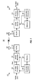
- FIGS. 5 and 6 show two embodiments of a frequency bin error estimator.
- FIG. 7 shows a process for performing frequency error estimation by despreading the received symbols.
- FIG. 8 shows a process for performing frequency error estimation by correlating the received symbols.
- FIG. 9 shows a process for performing frequency error estimation in stages.
- the frequency synchronization techniques described herein may be used for various communication systems such as an OFDM system, an orthogonal frequency division multiple access (OFDMA) system, a single-carrier frequency division multiple access (SC-FDMA) system, and so on.
- An OFDMA system utilizes OFDM.
- An SC-FDMA system may utilize interleaved FDMA (IFDMA) to transmit on subbands that are distributed across the system bandwidth, localized FDMA (LFDMA) to transmit on a block of adjacent subbands, or enhanced FDMA (EFDMA) to transmit on multiple blocks of adjacent subbands.
- IFDMA interleaved FDMA
- LFDMA localized FDMA
- EFDMA enhanced FDMA
- modulation symbols are sent in the frequency domain with OFDM and in the time domain with SC-FDMA.
- DVB-H and ISDB-T support digital transmission of multimedia over a terrestrial communication network.
- DVB-H has 3 modes of operation for FFT sizes of 2K, 4K and 8K.
- ISDB-T has 3 modes of operation for FFT sizes of 256, 512 and 1K.
- DVB-H is described in document ETSI EN 300 744, entitled “Digital Video Broadcasting (DVB); Framing structure, channel coding and modulation for digital terrestrial television," November 2004.
- ISDB-T is described in document ARIB STD-B31, entitled “Transmission System for Digital Terrestrial Television Broadcasting," July 2003. These documents are publicly available.
- FIG. 1 shows a block diagram of a transmitter 110 and a receiver 150 in an OFDM-based system 100, which may implement DVB-H, ISDB-T, and/or some other design.
- a transmit (TX) data processor 120 receives and processes (e.g., formats, encodes, interleaves, and symbol maps) traffic data to generate data symbols.
- a data symbol is a modulation symbol for traffic data
- a pilot symbol is a modulation symbol for pilot, which is data that is known a priori by both the transmitter and receiver
- a zero symbol is a signal value of zero.
- An OFDM modulator 130 receives and multiplexes the data symbols and pilot symbols onto data subbands and pilot subbands, respectively.
- a data subband is a subband used to send traffic data
- a pilot subband is a subband used to send pilot.
- a given subband may serve as a data subband in one OFDM symbol period and as a pilot subband in another OFDM symbol period.
- An OFDM symbol period is the duration of one OFDM symbol and is also referred to as a symbol period.
- the pilot symbols may be multiplexed with the data symbols as described below.
- OFDM modulator 130 obtains K transmit symbols for the K total subbands in each OFDM symbol period. Each transmit symbol may be a data symbol, a pilot symbol, or a zero symbol.
- OFDM modulator 130 transforms the K transmit symbols for each OFDM symbol period with a K-point inverse fast Fourier transform (IFFT) or inverse discrete Fourier transform (IDFT) to obtain a transformed symbol that contains K time-domain chips. OFDM modulator 130 then repeats a portion of the transformed symbol to generate an OFDM symbol. The repeated portion is often called a cyclic prefix or a guard interval and is used to combat frequency selective fading, which is a frequency response that varies across the system bandwidth due to multipath in a wireless channel. OFDM modulator 130 provides an OFDM symbol for each OFDM symbol period.
- a transmitter unit (TMTR) 132 receives and processes (e.g., converts to analog, amplifies, filters, and frequency upconverts) the OFDM symbols and generates a modulated signal, which is transmitted via an antenna 134 to receiver 150.
- TMTR transmitter unit
- an antenna 152 receives the modulated signal from transmitter 110 and provides a received signal to a receiver unit (RCVR) 154.
- Receiver unit 154 conditions (e.g., filters, amplifies, frequency downconverts, and digitizes) the received signal to obtain input samples.
- An OFDM demodulator (Demod) 160 processes the input samples as described below and obtains K received symbols for the K total subbands in each OFDM symbol period. The received symbols include received data symbols for the data subbands and received pilot symbols for the pilot subbands. OFDM demodulator 160 performs frequency synchronization to estimate and remove the frequency error at receiver 150.
- OFDM demodulator 160 also performs data demodulation/detection on the received data symbols with a channel estimate to obtain data symbol estimates, which are estimates of the data symbols sent by transmitter 110.
- a receive (RX) data processor 170 then processes (e.g., symbol demaps, deinterleaves, and decodes) the data symbol estimates to obtain decoded data.
- RX data processor 170 processes (e.g., symbol demaps, deinterleaves, and decodes) the data symbol estimates to obtain decoded data.
- the processing by OFDM demodulator 160 and RX data processor 170 is complementary to the processing by OFDM modulator 130 and TX data processor 120, respectively, at transmitter 110.
- Controllers/processors 140 and 180 control the operation of various processing units at transmitter 110 and receiver 150, respectively.
- Memories 142 and 182 store data and program codes for transmitter 110 and receiver 150, respectively.
- FIG. 2 shows an exemplary subband structure 200 for system 100.
- the overall system bandwidth of BW MHz is partitioned into multiple (K) subbands that are given indices of 0 through K -1, where K may be a configurable value.
- the spacing between adjacent subbands is BW/K MHz.
- the K total subbands are arranged into 12 disjoint interlaces.
- the 12 interlaces are disjoint in that each of the K subbands belongs in only one interlace.
- Each interlace contains approximately K/12 subbands that are uniformly distributed across the K total subbands such that consecutive subbands in the interlace are spaced apart by 12 subbands.
- interlace u for u ⁇ ⁇ 0,..., 11 ⁇ , contains subbands u, u + 12, u + 24, .... Index u is the interlace index as well as a subband offset that indicates the first subband in the interlace.
- FIG. 2 only shows four interlaces 0, 3, 6 and 9.
- FIG. 3A shows a pilot structure 300 for DVB-H.
- Pilot structure 300 includes a continual pilot and a scattered pilot.
- the continual pilot is sent on C subbands that are distributed across the system bandwidth, where C is dependent on the mode.
- the pilot is continual in that it is sent on the same C subbands in all OFDM symbol periods. These C subbands include subbands 0, 48, 54, ..., K -1 and are given in ETSI EN 300 744.
- the scattered pilot is sent on one interlace in each OFDM symbol period.
- the transmission timeline for DVB-H is partitioned into frames, with each frame including 68 OFDM symbols that are given indices of 0 through 67.
- the scattered pilot is sent on interlace 0 in OFDM symbol 0, interlace 3 in OFDM symbol 1, interlace 6 in OFDM symbol 2, interlace 9 in OFDM symbol 4, interlace 0 in OFDM symbol 5, and so on.
- the scattered pilot is thus sent on the same four interlaces in each set of 4 OFDM symbols.
- FIG. 3B shows a pilot structure 310 for ISDB-T.
- Pilot structure 310 includes only a scattered pilot that is sent on interlaces 0, 3, 6 and 9 in each set of 4 OFDM symbols.
- the transmission timeline for ISDB-T is also partitioned into frames, with each frame including 204 OFDM symbols that are given indices of 0 through 203.
- the scattered pilot is sent on interlace 0 in OFDM symbol 0 and cycles through interlaces 0, 3, 6 and 9 in the same manner as the scattered pilot for DVB-H.
- the pilot symbols for each OFDM symbol are generated based on a pseudo-random binary sequence (PBRS) that is derived from a specific generator polynomial.
- PBRS bit w k for k ⁇ ⁇ 0, ..., K -1 ⁇ , is used to generate a BPSK modulation symbol that is used as a pilot symbol for subband k .
- the pilot symbols for interlace u are generated with PBRS bits ⁇ w u , w u +12' w u +24, w u +36 , ... ⁇ .
- Table 1 lists the values for some parameters for the three modes in DVB-H and ISDB-T.
- N, K, C and S are given for one OFDM symbol.
- the number of scattered pilot subbands (S) for both DVB-H and ISDB-T and the number of continual pilot subbands (C) for DVB-H are dependent on the mode.
- K is an integer multiple of 12
- interlaces 0, 3, 6 and 9 contain the same number of pilot subbands.
- DVB-H K is not an integer multiple of 12, and interlace 0 contains one more pilot subband than interlaces 3, 6 and 9.
- the interlaces contain the same number of (S) pilot subbands.
- FIG. 4 shows a block diagram of an embodiment of OFDM demodulator 160 at receiver 150 in FIG. 1 .
- a pre-processor 410 receives and processes the input samples from receiver unit 154 and provides pre-processed samples.
- Pre-processor 410 may perform automatic gain control (AGC), timing acquisition, filtering, sample rate conversion, direct current (DC) offset removal, and/or other functions.
- AGC automatic gain control
- Pre-processor 410 may perform timing acquisition, filtering, sample rate conversion, direct current (DC) offset removal, and/or other functions.
- AGC automatic gain control
- filtering filtering
- sample rate conversion sample rate conversion
- DC direct current
- the integer portion of the frequency error is also called frequency bin error or coarse bin frequency error.
- a coarse frequency estimator 412 estimates the fractional frequency error ⁇ f based on the pre-processed samples and in a manner known in the art.
- a rotator 414 receives the estimated fractional frequency error ⁇ f from estimator 412 and the estimated frequency bin error m ⁇ from a frequency bin error estimator 420, removes the estimated total frequency error from the pre-processed samples, and provides frequency-corrected samples.
- a cyclic prefix removal unit 416 removes the cyclic prefix appended to each OFDM symbol and provides received samples.
- An FFT/DFT unit 418 performs a fast Fourier transform (FFT) or discrete Fourier transform (DFT) on the received samples for each OFDM symbol period and provides frequency-domain received symbols for the K total subbands.
- Frequency bin error estimator 420 estimates the frequency bin error based on the received pilot symbols and provides the estimated frequency bin error, as described below.
- Rotator 414 may remove the estimated frequency bin error from the pre-processed samples, as shown in FIG. 4 .
- a frequency bin correction unit can remove the estimated frequency bin error from the received data symbols (not shown in FIG. 4 ).
- a channel estimator 422 derives a channel estimate based on the received pilot symbols. The channel estimate may be a time-domain channel impulse response estimate or a frequency-domain channel frequency response estimate.
- a data demodulator 424 performs data demodulation/detection on the received data symbols with the channel estimate and provides data symbol estimates.
- OFDM demodulator 160 may include processing units for fine frequency tracking, fine time tracking, frame synchronization, and/or other functions.
- Frequency bin error estimator 420 estimates the frequency bin error and further determines the scattered pilot offset, which indicates the specific interlace used for the scattered pilot in each OFDM symbol period.
- the maximum frequency bin error is determined by the accuracy of the reference oscillator at receiver 150, the center frequency of the modulated signal being received, and the mode used by the system. For example, if the reference oscillator has a maximum error of 5 parts per million (ppm) and the center frequency is 800 MHz, then the maximum frequency error is ⁇ 4 KHz. This ⁇ 4 KHz frequency error corresponds to ⁇ 4 bins for a subband spacing of 1116 Hz for mode 3 in ISDB-T and to ⁇ 6 bins for a subband spacing of 697 Hz for mode 3 in DVB-H.
- the correct frequency bin error is one of 9 "frequency" hypotheses for -4, -3, -2, -1, 0, +1, +2, +3 and +4 bin errors.
- Receiver 150 typically does not have frame timing when first tuned to transmitter 110. In this case, for a given OFDM symbol, receiver 150 does not know whether the scattered pilot is being sent on interlace 0, 3, 6 or 9. As shown in FIG. 2 , a pilot offset of 0 corresponds to the scattered pilot being sent on interlace 0, a pilot offset of 1 corresponds to the scattered pilot being sent on interlace 3, a pilot offset of 2 corresponds to the scattered pilot being sent on interlace 6, and a pilot offset of 3 corresponds to the scattered pilot being sent on interlace 9. There is thus an ambiguity of 4 pilot offsets. Hence, the correct pilot offset is one of 4 "time" hypotheses for pilot offsets of 0, 1, 2 and 3.
- the frequency bin error estimation may be performed in various manners. In an embodiment, the estimation is performed based on an assumption that both frequency bin error and pilot offset are unknown. For this embodiment, multiple hypotheses are formed jointly for frequency and time. In another embodiment, the estimation is performed in two steps, with the first step determining the frequency bin error and the second step determining the pilot offset. For this embodiment, multiple hypotheses are formed separately for frequency and time.
- the frequency bin error estimation may also be performed based on various metrics. In an embodiment, the estimation is performed based on metrics derived from despreading the received symbols. In another embodiment, the estimation is performed based on metrics derived from correlating the received symbols.
- Table 2 lists four exemplary frequency bin error estimation schemes, the hypotheses and metrics for each scheme, and the system(s) for which each scheme is applicable. For clarity, schemes 1 and 4 are specifically described below.
- frequency bin error estimation scheme 1 in Table 2 multiple frequency/ time hypotheses are formed for different combinations of frequency bin error and pilot offset.
- One frequency/time hypothesis is the correct hypothesis for both frequency bin error and pilot offset, and the remaining frequency/time hypotheses are incorrect.
- S k ( l ) may be a data symbol or a pilot symbol.
- a frequency error of x bins results in the modulation symbol sent on subband k being received on subband k + x at the receiver.
- the factor e j 2 ⁇ x ⁇ G is due to phase rotation in the received symbols for OFDM symbol l + 1 relative to the phase of the received symbols for OFDM symbol l with a frequency error of x bins.
- each frequency/time hypothesis covers a set of four consecutive OFDM symbols l through l + 3.
- a given frequency/time hypothesis H x,y which corresponds to a hypothesized frequency error of x bins and a hypothesized pilot offset of y , may be evaluated as follows. First, the received symbols are extracted from pilot subbands corresponding to frequency bin error x and pilot offset y .
- the extracted received symbols for each OFDM symbol are then despread with the corresponding bits of the PBRS sequence to obtain despread symbols.
- the despread symbols for OFDM symbols l + 1, l + 2 and l + 3 are multiplied with e -j 2 ⁇ x ⁇ G , e -j 4 ⁇ x ⁇ G and e - j 6 ⁇ x ⁇ G , respectively, to account for the phase rotation across OFDM symbols due to the frequency error of x bins.
- the results of the processing are estimated channel gains (or simply, channel gains) for the pilot subbands.
- H x , 0 w 0 ⁇ Z x l , w 12 ⁇ Z x + 12 l , w 24 ⁇ Z x + 24 l , ... , w T ⁇ Z x + T l w 3 ⁇ Z x + 3 ⁇ l + 1 , w 15 ⁇ Z x + 15 ⁇ l + 1 , w 27 ⁇ Z x + 27 ⁇ l + 1 , ... , w T + 3 ⁇ Z x + T + 3 ⁇ l + 1 ⁇ e - j ⁇ 2 ⁇ ⁇ ⁇ x ⁇ G w 6 ⁇ Z x + 6 ⁇ l + 2 , w 18 ⁇ Z x + 18 ⁇ l + 2 , w 30 ⁇ Z x + 30 ⁇ l + 2 , ... , w T + 6
- Each hypothesis H x,y in equation (6) includes four rows of channel gains, one row for each OFDM symbol. Each row includes S channel gains for S pilot subbands in one OFDM symbol. The channel gains are derived from the received symbols that are extracted from different subbands depending on the frequency bin error x and the pilot offset y.
- a metric is derived for frequency/time hypothesis H x,y based on a channel impulse response estimate.
- the channel gains from the four OFDM symbols for hypothesis H x,y are first sorted based on subband indices.
- channel gains may be obtained for any number of interlaces and any number of subbands in each interlace.
- the length of the channel impulse response estimate is dependent on the number of channel gains and may be shorter than 4S.
- DVB-H has many more scattered pilot subbands than ISDB-T.
- a subset of the scattered pilot subbands may be used to derive the metric for each hypothesis. For example, the first 16, 32 and 64 pilot subbands in each OFDM symbol may be used for modes 1, 2 and 3, respectively, in DVB-H.
- the channel impulse response estimate for each hypothesis may then be derived using 64-, 128- and 256-point FFTs for modes 1, 2 and 3, respectively.
- the FFT size is four times the number of pilot subbands selected for use.
- the extracted received symbols are the received pilot symbols properly aligned in both time and frequency.
- the resultant despread symbols are good estimates of the channel gains.
- a channel impulse response estimate may then be derived based on these channel gains. This channel impulse response estimate includes a signal component that is above the noise floor.
- a metric may be defined based on the channel impulse response estimate in various manners.
- M x,y ( i ) may be obtained based on equation (9), (10) or (11).
- the L OFDM symbol sets may be adjacent to one another or spread out over time.
- a metric M x,y may be derived for hypothesis H x,y based on equation (9), (10), (11), (12) or some other equation.
- the FFT operation coherently sums the channel gains ⁇ H x,y ⁇ and provides the channel taps ⁇ h x,y ⁇ . This coherent sum provides high processing gain and yields good detection performance even in low SNR conditions.
- metric M x,y may be derived based on the channel gains ⁇ H x,y ⁇ in other manners, e.g., by summing the energies of the channel gains.
- a metric M x,y is obtained for each frequency/time hypothesis.
- the metrics for all frequency/time hypotheses may be compared, and the hypothesis with the largest metric may be provided as the correct hypothesis.
- the frequency bin error for the correct hypothesis may be provided to rotator 414, as shown in FIG. 4 .
- the pilot offset for the correct hypothesis may be provided to channel estimator 422 and possibly other processing units within receiver 150.
- FIG. 5 shows a block diagram of a frequency bin error estimator 420a, which is an embodiment of estimator 420 within OFDM demodulator 160 in FIG. 4 .
- a control unit 510 receives inputs indicative of the range of frequency errors (e.g., ⁇ 4 bins) and whether the pilot offset is known. Control unit 510 forms hypotheses covering all frequency and/or time uncertainty.
- a despreading unit 512 obtains received symbols for the K total subbands, extracts the received symbols from the proper subbands for the hypothesis H x,y being evaluated, performs despreading of the extracted received symbols with the PBRS sequence, rotates the despread symbols for each OFDM symbol by e -j 2 ⁇ x ⁇ G to obtain the channel gains ⁇ H x,y ⁇ , where ⁇ is 0, 1, 2 and 3 for the four OFDM symbols in a set being evaluated.
- Channel estimator 422 receives the channel gains for each hypothesis H x,y and derives a channel impulse response estimate ⁇ h x,y ⁇ for that hypothesis.
- a metric computation unit 514 derives a metric M x,y for each hypothesis based on the channel impulse response estimate, e.g., using any of the embodiments described above. Unit 514 may non-coherently sum multiple metrics obtained for different OFDM symbol sets as shown in equation (12) or may omit this non-coherent sum, e.g., for a fast fading channel.
- a detection unit 516 receives the metrics for all hypotheses, identifies the largest metric, and provides the hypothesis with the largest metric as the correct hypothesis.
- the frequency bin error may be determined based on the continual pilot that is sent on the same interlace in all OFDM symbol periods so that there is no ambiguity as to the pilot subbands.
- the pilot offset may be ascertained based on the scattered pilot. By decoupling the frequency bin error and the pilot offset, the frequency bin error may be determined with 13 frequency hypotheses for a frequency error range of ⁇ 6 bins, and the pilot offset may be determined with 4 time hypotheses.
- a frequency hypothesis H x corresponds to a hypothesized frequency error of x bins.
- the number of frequency hypotheses to evaluate is dependent on the frequency error range.
- Each frequency hypothesis may be evaluated as follows.
- continual pilot symbols are received on subbands k + x , for k ⁇ CP , where CP denotes the set of continual pilot subbands to be considered.
- CP may contain all or a subset of the continual pilot subbands.
- the correlation between two received symbols in two OFDM symbols l and l + 1 for each pilot subband may be expressed as: Z k + x l ⁇ Z k + x * ⁇ l + 1 ⁇ 16 9 ⁇ e - j ⁇ 2 ⁇ ⁇ ⁇ x ⁇ G ⁇ H k 2 .
- the correlation results may be accumulated across all pilot subbands, as follows: ⁇ k ⁇ CP Z k + x l ⁇ Z k + x * ⁇ l + 1 ⁇ 16 9 ⁇ e - j ⁇ 2 ⁇ ⁇ ⁇ x ⁇ G ⁇ ⁇ k ⁇ CP H k 2 .
- the correlation results may further be accumulated across multiple correlation intervals, as follows: ⁇ l ⁇ k ⁇ CP Z k + x l ⁇ Z k + x * ⁇ l + 1 ⁇ 16 9 ⁇ e - j ⁇ 2 ⁇ ⁇ x ⁇ G ⁇ ⁇ l ⁇ k ⁇ CP H k 2 .
- Each correlation interval corresponds to a different pair of OFDM symbols. For example, a first accumulated result may be obtained for OFDM symbols l and l + 1 as shown in equation (16), a second accumulated result may be obtained for OFDM symbols l + 1 and l + 2, a third accumulated result may be obtained for OFDM symbols l + 2 and l + 3, and a fourth accumulated result may be obtained for OFDM symbols l + 3 and l + 4. The four accumulated results may then be summed to obtain the overall result shown in equation (17). In general, the correlation results may be accumulated across any number of subbands and any number of OFDM symbols.
- hypothesized frequency bin error x is not equal to the actual frequency bin error m , or x ⁇ m . If hypothesis H x is not correct because the hypothesized frequency bin error x is not equal to the actual frequency bin error m , or x ⁇ m , then received data symbols are extracted from subbands k + x , for k ⁇ CP.
- the extracted received symbols may be correlated and accumulated across pilot subbands, as follows: ⁇ k ⁇ CP Z k + x l ⁇ Z k + x * ⁇ l + 1 ⁇ 16 9 ⁇ e - j ⁇ 2 ⁇ ⁇ ⁇ m ⁇ G ⁇ ⁇ k ⁇ CP H k + x - m 2 ⁇ D k + x - m l ⁇ D k + x - m * ⁇ l + 1 . Equation (20) indicates that the magnitude squares of the channel gains do not sum up coherently due to the random nature of the data symbols D k+x-m ( l ) and D k+x-m ( l + 1).
- Equation (21) indicates that the accumulated result approaches zero if the accumulation is performed over a sufficient number of OFDM symbols.
- a metric Q x a may be defined for hypothesis H x as follows:
- Q x a Re e j ⁇ 2 ⁇ ⁇ ⁇ x ⁇ G ⁇ ⁇ l ⁇ k ⁇ CP Z k + x l ⁇ Z k + x * ⁇ l + 1 .
- the correlation results Z k + x l ⁇ Z k + x * ⁇ l + 1 are coherently summed over both frequency and time, the accumulated result is rotated by e j 2 ⁇ x ⁇ G , and the real part of the rotated result is provided as metric Q x a .
- the single nodal peak may shift rapidly from one correlation interval to the next.
- the peak may be centered near 0° in one correlation interval and may shift to 180° in the next correlation interval.
- ⁇ k ( l) may thus be nearly out of phase in consecutive correlation intervals.
- the correlation results are (1) coherently summed over frequency to take advantage of the single nodal distribution of ⁇ k ( l ) for the pilot subbands and (2) non-coherently summed over time to account for fast and random changes in ⁇ k ( l ).
- Metric Q x f may provide better performance for a fast fading channel.
- metric Q x s is better for static and slow fading channels
- metric Q x f is better for a fast fading channel.
- ⁇ may also be a configurable value.
- a metric Q x may be derived for hypothesis H x based on equation (22), (24), (25), (26) or some other equation.
- the pilot offset may be determined based on the scattered pilot once the frequency bin error has been determined based on the continual pilot.
- a time hypothesis H y corresponds to a hypothesized pilot offset of y , which means that the scattered pilot is being sent on interlace 3 y in OFDM symbol period l .
- the correlation between two received symbols in OFDM symbol periods l and l + 4 for each pilot symbol may then be expressed as: Z m ⁇ + 3 ⁇ y + 12 ⁇ j l ⁇ Z m ⁇ + 3 ⁇ y + 12 ⁇ j * ⁇ l + 4 .
- a metric Qy may be derived for hypothesis H y by substituting Z m ⁇ +3y+12j (l) ⁇ Z m ⁇ + 3 ⁇ y + 12 ⁇ j * ⁇ l + 4 for Z k+x (l) ⁇ Z k + x * ⁇ l + 1 in the equations described above.
- Four metrics are obtained for four time hypotheses. The time hypothesis with the largest metric may be provided as the correct hypothesis.
- FIG. 6 shows a block diagram of a frequency bin error estimator 420b, which is another embodiment of estimator 420 within OFDM demodulator 160 in FIG. 4 .
- a control unit 610 receives inputs indicative of the range of frequency errors (e.g., ⁇ 4 bins) and whether the pilot offset is known. Control unit 610 forms a set of frequency hypotheses covering all frequency uncertainty and a set of time hypotheses covering all time uncertainty.
- a correlation unit 612 obtains received symbols for the K total subbands, extracts the received symbols from the proper subbands for hypothesis H x or H y being evaluated, performs correlation on the extracted received symbols, and provides correlation results for different subbands and correlation intervals.
- a metric computation unit 614 derives a metric Q x or Q y for each hypothesis based on the correlation results for that hypothesis, e.g., using any of the embodiments described above. Unit 614 may coherently sum the correlation results across subbands and may coherently or non-coherently sum across correlation intervals.
- a detection unit 616 receives the metrics for all frequency hypotheses, identifies the largest metric, and provides the frequency bin error for the frequency hypothesis with the largest metric as the estimated frequency bin error. Detection unit 616 also receives the metrics for all time hypotheses, identifies the largest metric, and provides the pilot offset for the time hypothesis with the largest metric as the correct pilot offset.
- hypotheses are formed jointly for frequency bin error and pilot offset, and each hypothesis is evaluated using correlation-based metrics, e.g., the metrics shown in equations (22), (24), (25) and/or (26).
- correlation-based metrics e.g., the metrics shown in equations (22), (24), (25) and/or (26).
- hypotheses are formed separately for frequency bin error and pilot offset, and each hypothesis is evaluated using despreading-based metrics, e.g., the metrics shown in equations (9), (10), (11) and/or (12).
- a scheme may also use a combination of despreading-based metric and correlation-based metric.
- a despreading-based metric may be used for frequency hypotheses
- a correlation-based metric may be used for time hypotheses.
- Other metrics defined in other manners may also be used to evaluate the hypotheses.
- FIG. 7 shows an embodiment of a process 700 for performing frequency error estimation by despreading the received symbols.
- Time-domain input samples are processed to obtain frequency-domain received symbols for the K total subbands (block 710).
- Multiple hypotheses are formed for different frequency bin errors (or bin offsets), different pilot offsets, or different combinations of frequency bin error and pilot offset (block 712).
- received symbols are extracted from the proper subbands determined by the hypothesis (block 714).
- the extracted received symbols are hypothesized to be for (1) a scattered pilot that is sent on different sets of subbands in different symbol periods and/or (2) a continual pilot that is sent on the same set of subbands in all symbol periods.
- the extracted received symbols for each hypothesis are despread with a scrambling sequence, e.g., the PBRS sequence, to obtain despread symbols for that hypothesis (block 716).
- a metric is then derived for each hypothesis based on the despread symbols for that hypothesis (block 718).
- a channel impulse response estimate may be derived for each hypothesis based on the despread symbols for the hypothesis.
- the metric for each hypothesis may then be derived based on the channel impulse response estimate for the hypothesis, as described above. In any case, the frequency bin error and/or the pilot offset are determined based on the metrics for all hypotheses evaluated (block 720).
- FIG. 8 shows an embodiment of a process 800 for performing frequency error estimation by correlating the received symbols.
- Time-domain input samples are processed to obtain frequency-domain received symbols for the K total subbands (block 810).
- Multiple hypotheses are formed for different frequency bin errors, different pilot offsets, or different combinations of frequency bin error and pilot offset (block 812).
- received symbols in multiple symbol periods are extracted from the proper subbands determined by the hypothesis (block 814).
- the extracted received symbols are hypothesized to be for a scattered pilot and/or a continual pilot.
- correlation is performed on the extracted received symbols for each subband to obtain correlation results for that hypothesis (block 816).
- a metric is then derived for each hypothesis based on the correlation results for all subbands and correlation intervals for that hypothesis (block 818).
- the metric for each hypothesis may be derived by coherently summing the correlation results across subbands and coherently or non-coherently summing the correlation results across correlation intervals.
- the metric may also be derived based on a weighted sum of metrics obtained with different accumulation schemes, e.g., as shown in equation (26).
- the frequency bin error and/or the pilot phase is determined based on the metrics for all hypotheses evaluated (block 820).
- FIG. 9 shows an embodiment of a process 900 for performing frequency error estimation in multiple stages.
- a frequency error is determined based on a first pilot (e.g., a continual pilot) by evaluating a first set of hypotheses for a range of frequency errors (block 912).
- a pilot offset is determined based on a second pilot (e.g., a scattered pilot) by evaluating a second set of hypotheses for a set of pilot offsets and with the frequency error determined from the first pilot (block 914).
- the two sets of hypotheses may be evaluated using the same or different metrics.
- Process 700, 800, and/or 900 may be performed by frequency bin error estimator 420 in FIG. 4 , controller/processor 180 in FIG.. 1 , and/or some other processing unit at receiver 150.
- the techniques described herein may be implemented by various means. For example, these techniques may be implemented in hardware, firmware, software, or a combination thereof.
- the processing units used to perform frequency error estimation may be implemented within one or more application specific integrated circuits (ASICs), digital signal processors (DSPs), digital signal processing devices (DSPDs), programmable logic devices (PLDs), field programmable gate arrays (FPGAs), processors, controllers, micro-controllers, microprocessors, electronic devices, other electronic units designed to perform the functions described herein, or a combination thereof.
- ASICs application specific integrated circuits
- DSPs digital signal processors
- DSPDs digital signal processing devices
- PLDs programmable logic devices
- FPGAs field programmable gate arrays
- processors controllers, micro-controllers, microprocessors, electronic devices, other electronic units designed to perform the functions described herein, or a combination thereof.
- the techniques may be implemented with modules (e.g., procedures, functions, and so on) that perform the functions described herein.
- the software codes may be stored in a memory (e.g., memory 182 in FIG. 1 ) and executed by a processor (e.g., processor 180).
- the memory may be implemented within the processor or external to the processor.
Landscapes
- Engineering & Computer Science (AREA)
- Signal Processing (AREA)
- Computer Networks & Wireless Communication (AREA)
- Power Engineering (AREA)
- Mobile Radio Communication Systems (AREA)
- Synchronisation In Digital Transmission Systems (AREA)
- Radio Transmission System (AREA)
Applications Claiming Priority (2)
| Application Number | Priority Date | Filing Date | Title |
|---|---|---|---|
| US11/313,555 US8130726B2 (en) | 2005-12-20 | 2005-12-20 | Coarse bin frequency synchronization in a communication system |
| EP06850959A EP1999922A2 (de) | 2005-12-20 | 2006-12-14 | Frequenzsynchronisation für die mehrträgerübertragung |
Related Parent Applications (1)
| Application Number | Title | Priority Date | Filing Date |
|---|---|---|---|
| EP06850959.5 Division | 2006-12-14 |
Publications (2)
| Publication Number | Publication Date |
|---|---|
| EP2228962A2 true EP2228962A2 (de) | 2010-09-15 |
| EP2228962A3 EP2228962A3 (de) | 2011-07-27 |
Family
ID=38173422
Family Applications (2)
| Application Number | Title | Priority Date | Filing Date |
|---|---|---|---|
| EP10006180A Withdrawn EP2228962A3 (de) | 2005-12-20 | 2006-12-14 | Grobe Bin-Frequenzsynchronisierung in einem Kommunikationssystem |
| EP06850959A Withdrawn EP1999922A2 (de) | 2005-12-20 | 2006-12-14 | Frequenzsynchronisation für die mehrträgerübertragung |
Family Applications After (1)
| Application Number | Title | Priority Date | Filing Date |
|---|---|---|---|
| EP06850959A Withdrawn EP1999922A2 (de) | 2005-12-20 | 2006-12-14 | Frequenzsynchronisation für die mehrträgerübertragung |
Country Status (6)
| Country | Link |
|---|---|
| US (2) | US8130726B2 (de) |
| EP (2) | EP2228962A3 (de) |
| JP (1) | JP5065294B2 (de) |
| KR (1) | KR101022080B1 (de) |
| CN (3) | CN102664856A (de) |
| WO (1) | WO2007117325A2 (de) |
Families Citing this family (28)
| Publication number | Priority date | Publication date | Assignee | Title |
|---|---|---|---|---|
| DE602004010520T2 (de) | 2003-07-14 | 2008-11-06 | Thomson Licensing | Vorrichtung und verfahren zur bereitstellung einer agc-funktion durch verwendung mehrerer rückkopplungsquellen |
| US7474611B2 (en) * | 2005-04-21 | 2009-01-06 | Telefonaktiebolaget L M Ericsson (Publ) | Reduced complexity channel estimation in OFDM systems |
| US8130726B2 (en) * | 2005-12-20 | 2012-03-06 | Qualcomm Incorporated | Coarse bin frequency synchronization in a communication system |
| US8254865B2 (en) * | 2006-04-07 | 2012-08-28 | Belair Networks | System and method for frequency offsetting of information communicated in MIMO-based wireless networks |
| US7894539B2 (en) * | 2006-07-24 | 2011-02-22 | Industrial Technology Research Institute | Method and device for estimating integer carrier frequency offset |
| KR101100791B1 (ko) * | 2006-10-16 | 2012-01-02 | 닛본 덴끼 가부시끼가이샤 | 수신 방법 및 수신 장치 |
| DE102007023881A1 (de) * | 2007-03-26 | 2008-10-02 | Rohde & Schwarz Gmbh & Co. Kg | Verfahren und Vorrichtung zur Ermittlung einer unverkürzten Kanalimpulsantwort in einem OFDM-Übertragungssystem |
| CN101039303B (zh) * | 2007-04-06 | 2011-05-11 | 威盛电子股份有限公司 | 模式及保护间隔的检测方法、装置及系统 |
| US7801020B2 (en) * | 2007-08-29 | 2010-09-21 | Intel Corporation | Mobile channel estimation algorithm for DVB-H COFDM demodulator |
| AU2008292822A1 (en) * | 2007-08-31 | 2009-03-05 | Nextivity, Inc. | OFDM modem using pilot sub-carrier structure |
| US8045628B2 (en) * | 2007-10-18 | 2011-10-25 | Nokia Corporation | Digital video broadcast service discovery |
| KR100932626B1 (ko) | 2007-12-13 | 2009-12-17 | 한국전자통신연구원 | 직접 시퀀스 확산 스펙트럼 방식의 혼성 역확산 장치 |
| JP5347792B2 (ja) * | 2009-07-16 | 2013-11-20 | ソニー株式会社 | 信号処理装置、信号処理方法、及び、受信システム |
| CN102006128B (zh) * | 2010-11-01 | 2014-02-26 | 华为技术有限公司 | 终端频率偏移检测方法、装置及系统 |
| US20130315323A1 (en) * | 2011-04-24 | 2013-11-28 | Broadcom Corporation | Traveling pilots within single user, multiple user, multiple access, and/or MIMO wireless communications |
| KR102029467B1 (ko) * | 2012-01-05 | 2019-10-07 | 한국전자통신연구원 | 자동 주파수 제어 장치 및 방법 |
| US9479218B2 (en) * | 2013-04-22 | 2016-10-25 | Mediatek Singapore Pte Ltd. | Methods for LTE cell search with large frequency offset |
| WO2014194928A1 (en) * | 2013-06-03 | 2014-12-11 | Telefonaktiebolaget L M Ericsson (Publ) | Distortion suppression for wireless transmission |
| CN103414544B (zh) * | 2013-07-12 | 2016-08-10 | 东南大学 | 通信系统中多相正交互补序列集合的生成方法 |
| EP3055932B1 (de) * | 2013-10-07 | 2023-03-01 | Decawave Ltd. | Empfänger für ein ultrabreitbandkommunikationssystem |
| US10349404B2 (en) * | 2016-04-22 | 2019-07-09 | Qualcomm Incorporated | Discovery reference signal transmission and decoding and measurement techniques in a wireless communication system |
| WO2018206666A1 (en) * | 2017-05-12 | 2018-11-15 | Telefonaktiebolaget Lm Ericsson (Publ) | Wireless communication device, network node, method and computer program for achieving synchronisation |
| US11057257B2 (en) | 2017-09-18 | 2021-07-06 | Telefonaktiebolaget Lm Ericsson (Publ) | Method and device for timing alignment |
| FR3072780B1 (fr) * | 2017-10-25 | 2020-08-28 | Airbus Defence & Space Sas | Procede et dispositif recepteur pour l’estimation d’un decalage frequentiel et d’une derive frequentielle d’un signal utile |
| US10509116B2 (en) | 2018-04-26 | 2019-12-17 | DecaWave, Ltd. | Method and apparatus for determining location using phase difference of arrival |
| US11422220B2 (en) | 2020-06-17 | 2022-08-23 | Qorvo Us, Inc. | Method and apparatus for determining the angle of departure |
| US11128342B2 (en) | 2019-02-02 | 2021-09-21 | DecaWave, Ltd. | Method and apparatus for determining the angle of departure |
| US20220397629A1 (en) | 2019-02-02 | 2022-12-15 | DecaWave, Ltd. | Method and apparatus for determining the angle of departure |
Family Cites Families (30)
| Publication number | Priority date | Publication date | Assignee | Title |
|---|---|---|---|---|
| FR2743967B1 (fr) * | 1996-01-18 | 1998-03-27 | France Telecom | Procede et dispositif de synchronisation temporelle d'un recepteur d'un signal multiporteuse |
| US5982811A (en) * | 1996-07-12 | 1999-11-09 | General Electric Company | Method for efficient sampling in a correlator |
| CA2183140C (en) * | 1996-08-12 | 2001-11-20 | Telecommunications Research Laboratories | Ofdm timing and frequency recovery system |
| IL120210A (en) | 1997-02-13 | 1999-12-31 | Dspc Tech Ltd | Synchronization system and method for digital communication systems |
| US6307840B1 (en) * | 1997-09-19 | 2001-10-23 | Qualcomm Incorporated | Mobile station assisted timing synchronization in CDMA communication system |
| US6249539B1 (en) | 1998-06-15 | 2001-06-19 | Qualcomm Incorporated | System and method for narrowing the range of frequency uncertainty of a doppler shifted signal |
| US6163524A (en) * | 1998-10-19 | 2000-12-19 | Telefonaktiebolaget Lm Ericsson (Publ) | Code allocation in CDMA |
| US6519300B1 (en) | 1998-11-12 | 2003-02-11 | Ericsson Inc. | System and method for automatic frequency correction in a pilot symbol assisted demodulator |
| US6452961B1 (en) * | 2000-09-12 | 2002-09-17 | Interstate Electronics Corporation | Massively paralleled sequential test algorithm |
| KR100358120B1 (ko) * | 2000-10-20 | 2002-10-25 | 한국전자통신연구원 | 동일대역 인접채널 방식의 디지털 오디오 방송 전송 시스템 |
| KR100402906B1 (ko) * | 2001-02-08 | 2003-10-22 | (주)아이앤씨테크놀로지 | 직교주파수분할다중방식에서의 주파수 오프셋 동기화 장치및 방법 |
| US7088782B2 (en) * | 2001-04-24 | 2006-08-08 | Georgia Tech Research Corporation | Time and frequency synchronization in multi-input, multi-output (MIMO) systems |
| JP3757144B2 (ja) | 2001-10-18 | 2006-03-22 | 株式会社メガチップス | Ofdm受信装置およびofdm信号の受信方法 |
| US6901243B2 (en) * | 2001-11-08 | 2005-05-31 | Qualcomm, Incorporated | Method and apparatus for mitigating adjacent channel interference in a wireless communication system |
| ATE288650T1 (de) | 2001-11-16 | 2005-02-15 | Com Res Gmbh Solutions For Com | Verfahren und system zur frequenzoffsetschätzung für trägermodulierte digitale kommunikationssysteme |
| AU2003268227A1 (en) * | 2002-08-28 | 2004-03-19 | Zyray Wireless, Inc. | Iterative multi-stage detection technique for a diversity receiver having multiple antenna elements |
| US7453792B2 (en) * | 2002-11-14 | 2008-11-18 | Edgewater Computer Systems, Inc. | Receiver architecture for pilot based OFDM systems |
| KR100555722B1 (ko) | 2003-05-20 | 2006-03-03 | 삼성전자주식회사 | 다중 반송파 수신 시스템의 정수배 주파수 옵셋 추정 장치및 그의 정수배 주파수 옵셋 추정방법 |
| US20050063298A1 (en) | 2003-09-02 | 2005-03-24 | Qualcomm Incorporated | Synchronization in a broadcast OFDM system using time division multiplexed pilots |
| US7356073B2 (en) * | 2003-09-10 | 2008-04-08 | Nokia Corporation | Method and apparatus providing an advanced MIMO receiver that includes a signal-plus-residual-interference (SPRI) detector |
| WO2005027353A2 (en) | 2003-09-12 | 2005-03-24 | Ems Technologies Canada, Ltd. | Hybrid frequency offset estimator |
| US7072783B2 (en) * | 2003-12-03 | 2006-07-04 | Motorola, Inc. | Frequency and timing error estimation and corresponding channel characterization in a communication system |
| US7746760B2 (en) | 2004-01-08 | 2010-06-29 | Qualcomm Incorporated | Frequency error estimation and frame synchronization in an OFDM system |
| KR20070053655A (ko) | 2004-03-05 | 2007-05-25 | 넥스트넷 와이어리스 인크. | 적응 변조를 위한 시스템 및 방법 |
| US8000377B2 (en) * | 2004-05-24 | 2011-08-16 | General Dynamics C4 Systems, Inc. | System and method for variable rate multiple access short message communications |
| US7692587B2 (en) * | 2004-09-22 | 2010-04-06 | Rosum Corporation | Rapid acquisition and correlation of synchronization codes for mobile devices with limited memory and computational power |
| US20070004465A1 (en) * | 2005-06-29 | 2007-01-04 | Aris Papasakellariou | Pilot Channel Design for Communication Systems |
| US8345733B2 (en) * | 2005-09-13 | 2013-01-01 | At&T Intellectual Property I, Lp | Method and apparatus for equalizing signals |
| US8009745B2 (en) * | 2005-11-15 | 2011-08-30 | Qualcomm Incorporated | Time tracking for a receiver with guard interval correlation |
| US8130726B2 (en) * | 2005-12-20 | 2012-03-06 | Qualcomm Incorporated | Coarse bin frequency synchronization in a communication system |
-
2005
- 2005-12-20 US US11/313,555 patent/US8130726B2/en not_active Expired - Fee Related
-
2006
- 2006-12-14 EP EP10006180A patent/EP2228962A3/de not_active Withdrawn
- 2006-12-14 KR KR1020087016914A patent/KR101022080B1/ko not_active Expired - Fee Related
- 2006-12-14 CN CN2012101352189A patent/CN102664856A/zh active Pending
- 2006-12-14 EP EP06850959A patent/EP1999922A2/de not_active Withdrawn
- 2006-12-14 CN CN2012101341697A patent/CN102655490A/zh active Pending
- 2006-12-14 JP JP2008547692A patent/JP5065294B2/ja not_active Expired - Fee Related
- 2006-12-14 CN CNA200680047891XA patent/CN101341707A/zh active Pending
- 2006-12-14 WO PCT/US2006/062125 patent/WO2007117325A2/en not_active Ceased
-
2011
- 2011-11-10 US US13/293,705 patent/US20120288037A1/en not_active Abandoned
Non-Patent Citations (1)
| Title |
|---|
| None |
Also Published As
| Publication number | Publication date |
|---|---|
| US20120288037A1 (en) | 2012-11-15 |
| KR20080075554A (ko) | 2008-08-18 |
| US8130726B2 (en) | 2012-03-06 |
| US20070140323A1 (en) | 2007-06-21 |
| WO2007117325A3 (en) | 2008-07-24 |
| EP1999922A2 (de) | 2008-12-10 |
| KR101022080B1 (ko) | 2011-03-17 |
| WO2007117325A2 (en) | 2007-10-18 |
| CN102655490A (zh) | 2012-09-05 |
| CN102664856A (zh) | 2012-09-12 |
| CN101341707A (zh) | 2009-01-07 |
| EP2228962A3 (de) | 2011-07-27 |
| JP5065294B2 (ja) | 2012-10-31 |
| JP2009521193A (ja) | 2009-05-28 |
Similar Documents
| Publication | Publication Date | Title |
|---|---|---|
| EP2228962A2 (de) | Grobe Bin-Frequenzsynchronisierung in einem Kommunikationssystem | |
| EP1706976B1 (de) | Frequenzfehlerschätzung und rahmensynchronisation in einem ofdm-system | |
| KR100947794B1 (ko) | 미세 타이밍 획득 | |
| KR101036778B1 (ko) | 시분할 멀티플렉싱 파일럿을 이용하는 브로드캐스트ofdm 시스템에서의 동기화 | |
| KR100945701B1 (ko) | 무선 통신 시스템에서의 신호 획득 | |
| US20090190675A1 (en) | Synchronization in a broadcast ofdm system using time division multiplexed pilots | |
| JP2002511710A (ja) | 多重搬送波システムにおける周波数粗同期 | |
| JP2011502454A (ja) | 時分割多重化パイロットを使用する同報ofdmシステムにおける同期化 | |
| EP2245814B1 (de) | Rahmen-Takt- und Trägerfrequenzwiederherstellung für frequenzselektive Signale | |
| HK1117974A (en) | Fine timing acquisition | |
| HK1107880B (en) | Method and apparatus for signal acquisition in a wireless communication system |
Legal Events
| Date | Code | Title | Description |
|---|---|---|---|
| PUAI | Public reference made under article 153(3) epc to a published international application that has entered the european phase |
Free format text: ORIGINAL CODE: 0009012 |
|
| 17P | Request for examination filed |
Effective date: 20100615 |
|
| AC | Divisional application: reference to earlier application |
Ref document number: 1999922 Country of ref document: EP Kind code of ref document: P |
|
| AK | Designated contracting states |
Kind code of ref document: A2 Designated state(s): AT BE BG CH CY CZ DE DK EE ES FI FR GB GR HU IE IS IT LI LT LU LV MC NL PL PT RO SE SI SK TR |
|
| RIN1 | Information on inventor provided before grant (corrected) |
Inventor name: PATEL, SHIMMAN Inventor name: GLAZKO, SERGUEI A. Inventor name: LAI, KUEI-CHIANG |
|
| PUAL | Search report despatched |
Free format text: ORIGINAL CODE: 0009013 |
|
| AK | Designated contracting states |
Kind code of ref document: A3 Designated state(s): AT BE BG CH CY CZ DE DK EE ES FI FR GB GR HU IE IS IT LI LT LU LV MC NL PL PT RO SE SI SK TR |
|
| RIC1 | Information provided on ipc code assigned before grant |
Ipc: H04L 27/26 20060101AFI20100722BHEP Ipc: H04L 27/38 20060101ALI20110620BHEP Ipc: H04L 25/02 20060101ALI20110620BHEP |
|
| RIC1 | Information provided on ipc code assigned before grant |
Ipc: H04L 27/38 20060101ALI20130718BHEP Ipc: H04L 25/02 20060101ALI20130718BHEP Ipc: H04L 27/26 20060101AFI20130718BHEP |
|
| GRAP | Despatch of communication of intention to grant a patent |
Free format text: ORIGINAL CODE: EPIDOSNIGR1 |
|
| INTG | Intention to grant announced |
Effective date: 20130930 |
|
| STAA | Information on the status of an ep patent application or granted ep patent |
Free format text: STATUS: THE APPLICATION IS DEEMED TO BE WITHDRAWN |
|
| 18D | Application deemed to be withdrawn |
Effective date: 20140211 |