EP2228829A2 - Solar battery module device - Google Patents
Solar battery module device Download PDFInfo
- Publication number
- EP2228829A2 EP2228829A2 EP10001435A EP10001435A EP2228829A2 EP 2228829 A2 EP2228829 A2 EP 2228829A2 EP 10001435 A EP10001435 A EP 10001435A EP 10001435 A EP10001435 A EP 10001435A EP 2228829 A2 EP2228829 A2 EP 2228829A2
- Authority
- EP
- European Patent Office
- Prior art keywords
- solar cell
- cell module
- reinforcing frame
- frame
- solar battery
- Prior art date
- Legal status (The legal status is an assumption and is not a legal conclusion. Google has not performed a legal analysis and makes no representation as to the accuracy of the status listed.)
- Granted
Links
- 230000003014 reinforcing effect Effects 0.000 claims abstract description 118
- 238000004519 manufacturing process Methods 0.000 description 5
- 239000000758 substrate Substances 0.000 description 5
- 238000010276 construction Methods 0.000 description 4
- 239000000428 dust Substances 0.000 description 3
- 238000000034 method Methods 0.000 description 3
- XLYOFNOQVPJJNP-UHFFFAOYSA-N water Substances O XLYOFNOQVPJJNP-UHFFFAOYSA-N 0.000 description 3
- 238000007796 conventional method Methods 0.000 description 2
- 230000000694 effects Effects 0.000 description 2
- 239000011521 glass Substances 0.000 description 2
- 238000003780 insertion Methods 0.000 description 2
- 230000037431 insertion Effects 0.000 description 2
- 239000011347 resin Substances 0.000 description 2
- 229920005989 resin Polymers 0.000 description 2
- 238000007789 sealing Methods 0.000 description 2
- XAGFODPZIPBFFR-UHFFFAOYSA-N aluminium Chemical compound [Al] XAGFODPZIPBFFR-UHFFFAOYSA-N 0.000 description 1
- 229910052782 aluminium Inorganic materials 0.000 description 1
- 238000005452 bending Methods 0.000 description 1
- 230000007257 malfunction Effects 0.000 description 1
- 239000011159 matrix material Substances 0.000 description 1
Images


Classifications
-
- H—ELECTRICITY
- H02—GENERATION; CONVERSION OR DISTRIBUTION OF ELECTRIC POWER
- H02S—GENERATION OF ELECTRIC POWER BY CONVERSION OF INFRARED RADIATION, VISIBLE LIGHT OR ULTRAVIOLET LIGHT, e.g. USING PHOTOVOLTAIC [PV] MODULES
- H02S30/00—Structural details of PV modules other than those related to light conversion
- H02S30/10—Frame structures
-
- F—MECHANICAL ENGINEERING; LIGHTING; HEATING; WEAPONS; BLASTING
- F24—HEATING; RANGES; VENTILATING
- F24S—SOLAR HEAT COLLECTORS; SOLAR HEAT SYSTEMS
- F24S25/00—Arrangement of stationary mountings or supports for solar heat collector modules
-
- Y—GENERAL TAGGING OF NEW TECHNOLOGICAL DEVELOPMENTS; GENERAL TAGGING OF CROSS-SECTIONAL TECHNOLOGIES SPANNING OVER SEVERAL SECTIONS OF THE IPC; TECHNICAL SUBJECTS COVERED BY FORMER USPC CROSS-REFERENCE ART COLLECTIONS [XRACs] AND DIGESTS
- Y02—TECHNOLOGIES OR APPLICATIONS FOR MITIGATION OR ADAPTATION AGAINST CLIMATE CHANGE
- Y02E—REDUCTION OF GREENHOUSE GAS [GHG] EMISSIONS, RELATED TO ENERGY GENERATION, TRANSMISSION OR DISTRIBUTION
- Y02E10/00—Energy generation through renewable energy sources
- Y02E10/50—Photovoltaic [PV] energy
Definitions
- the present invention relates to a solar battery module device installed on a construction such as a house and a building.
- solar battery module devices with the following configuration are used at various places and for various purposes.
- a transparent substrate (glass) is arranged at a light-receiving side, plural solar battery cells connected in series, or in parallel, are arranged on the back side of the transparent substrate, and the solar battery cells are then sealed with a sealing resin to constitute a solar cell module.
- a frame is fitted to an outer-edge portion of the solar cell module, thereby providing a solar battery module device. Bigger and bigger solar battery module devices are being manufactured in recent years with the aim to lower cost per unit output and to shorten the time required for production and line connection work. However, with an increase in the size, the load resistance performance of the surface of the transparent substrate degrades. In this solar battery module device, a predetermined strength is maintained by the transparent substrate and the frame.
- Solar battery module devices are generally installed on a construction, such as a house and a building, where they are exposed to the weather.
- a positive pressure that is operative to vertically press down the solar battery module device acts on the solar battery module device.
- a negative pressure that is operative to push the solar battery module device acts on the solar battery module device due to wind and the like.
- the top surface of the solar cell module which functions as a light-receiving surface, has a wide planer structure with a large area, the module is vertically bent in a curve when receiving the positive pressure and the negative pressure.
- a solar battery module device including a solar cell module formed by arranging a plurality of solar battery cells; a rack-shaped frame having a substantially rectangular shape supporting an outer-edge portion of the solar cell module by surrounding a whole periphery of the outer-edge portion; and a reinforcing frame that is bridged over between two opposite sides of the rack-shaped frame by forming a predetermined gap between the reinforcing frame and a back surface of the solar cell module, and supports the solar cell module by being brought into contact with the back surface of the solar cell module when the solar cell module is bent, wherein the reinforcing frame is engaged with engagement notches formed on the back surface of the rack-shaped frame.
- the reinforcing frame is positioned by being engaged with engagement notches formed on a back surface of a rack-shaped frame, the reinforcing frame can be easily fitted to the rack-shaped frame.
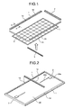
- Fig. 1 is a perspective view of a state in an initial step in an assembly process of a solar battery module device according to a first embodiment of the present invention.
- Fig. 2 is a perspective view of a state that a reinforcing frame is fitted from a back side to an intermediate assembly, the intermediate assembly being an article obtained by fixing a rack-shaped frame to an outer-edge portion of a solar cell module.
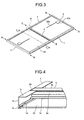
- Fig. 3 is a perspective view of a state that fitting of the reinforcing frame to the intermediate assembly is completed.
- Fig. 4 is an enlarged perspective view of a portion B where the reinforcing frame is engaged with a notch of the rack-shaped frame in Fig. 3 .
- Fig. 1 is a perspective view of a state in an initial step in an assembly process of a solar battery module device according to a first embodiment of the present invention.
- Fig. 2 is a perspective view of a state that a reinforcing frame is fitted from a back side to an intermediate assembly, the
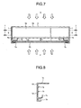
- FIG. 5 is a cross-sectional arrow view cut along a line A-A in Fig. 1 , depicting a cross-sectional shape of a long-side frame.
- Fig. 6 is a perspective view depicting in detail the shape of the reinforcing frame.
- Fig. 7 is a cross-sectional arrow view cut along a line C-C in Fig. 3 , depicting a state that a predetermined space is formed between the solar cell module and the reinforcing frame.
- Fig. 1 depicts a state that the solar cell module is viewed from a front side (light receiving surface) thereof.
- Figs. 2 and 3 depict a state that the solar cell module is viewed from a back side thereof.
- the solar battery module device includes a solar cell module 20 of a substantially rectangular plane shape. Furthermore, a rack-shaped frame 10 of a rectangular rack shape is provided surrounding the whole periphery of an outer-edge portion of the solar cell module 20 to support the solar cell module 20 via the outer-edge portion. Moreover, a reinforcing frame 3 fitted to the rack-shaped frame 10.
- the solar cell module 20 includes a plurality of series-connected or parallel-connected solar battery cells 15 that are arranged in a two-dimensional matrix.
- the whole surface of a light-receiving surface side of the solar battery cells 15 is covered by a transparent substrate (glass).
- the solar battery cells 15 are sealed with a sealing resin.
- the rack-shaped frame 10 is an extrusion-molded product made of aluminum, for example, and is configured by a pair of opposite long-side frames (first frames) 1, 1, and a pair of short-side frames (second frames) 2, 2 coupled between both ends of the long-side frames 1, 1.
- the pair of long-side frames 1, 1 and the pair of short-side frames 2, 2 are coupled to each other to form the rack-shaped frame 10 of a rectangular rack shape.
- the rack-shaped frame 10 reinforces the solar cell module 20 and is fitted to a mount (not shown) provided on a construction such as a house and a building.
- the reinforcing frame 3 is fitted to the rack-shaped frame 10 from the back side of the solar cell module 20.
- engagement notches 1d, 1d for engaging the reinforcing frame 3 are provided at central portions of back surfaces of the two long-side frames 1, 1. Both ends of the reinforcing frame 3 are settled in these engagement notches 1d, 1d from the back side, and are fitted to the long-side frames 1, 1. That is, both ends of the reinforcing frame 3 are inserted into the engagement notches 1d, 1d from the back side of the solar cell module 20, and are fitted to the long-side frames 1, 1. Terminal boxes 20a and cables 20b, which extend from the terminal boxes 20a, are also provided on the back surface of the solar cell module 20.
- the reinforcing frame 3 is fitted to the rack-shaped frame 10 by being bridged over between the opposite long-side frames 1, 1 of the rack-shaped frame 10 as described above.
- each end of the reinforcing frame 3 is engaged with the engagement notch 1d provided on the back surface of the long-side frame 1 and is accurately positioned.
- the short-side frames 2, 2 are fastened to the long-side frames 1, 1 by screws (first fixing screws) (not shown) inserted into through-holes formed at the ends of the long-side frames 1, 1 from directions of arrows D in Fig. 3 .
- the reinforcing frame 3 is fastened by screws (second fixing screws) 7 ( Fig.
- the long-side frames 1, 1 have a cross section in a substantially U shape to have predetermined strength.
- Each long-side frame 1 has a plane-shaped frame main body 1a extended to a direction perpendicular to the solar cell module 20, a module supporting unit 1b extended from an edge of the frame main body 1a at a side of the solar cell module 20 to the inside of the rack-shaped frame 10 and supporting the solar cell module 20, and an internal flange 1c formed by being extended from the frame main body 1a at an opposite side of the module supporting unit 1b to the inside of the rack-shaped frame 10.
- the module supporting unit 1b has a cross section of a substantially U shape having an opening inside the rack-shaped frame 10, and supports the outer-edge portion of the solar cell module 20 by holding the outer-edge portion at the inside of the U shape.
- the internal flange 1c extends in direction that is parallel to the solar cell module 20.
- the rack-shaped frame 10 has the internal flange 1c fitted to a mount (not shown), and supports the solar cell module 20 from the mount.
- the engagement notch 1d is formed by having the internal flange 1c notched by only a width of the reinforcing frame 3.
- a front edge at the back side of the module supporting unit 1b having the cross section of a substantially U shape is formed to be folded to the back side, and it is a positioning projection (a vertical-movement locking unit) 1e that positions the reinforcing frame 3 in a depth direction by being brought into contact with the reinforcing frame 3 when the reinforcing frame 3 is inserted into the engagement notch 1d.
- the reinforcing frame 3 has a substantially H shape in its cross section, and includes a plane-shaped frame main body 3a that extendes in a direction that is perpendicular to the solar cell module 20, the back side flange 3b spread from a back-surface edge of the frame main body 3a to both sides in parallel with the solar cell module 20, and a module-side flange 3c spread from an edge at a side of the solar cell module 20 of the frame main body 3a to both sides in parallel with the solar cell module 20.
- Two end-surface screw holes 3d are formed on an end surface of the frame main body 3a.
- the positioning projection (the vertical-movement locking unit) 1e that restricts a movement of the reinforcing frame to a direction of the solar cell module by being brought into contact with the reinforcing frame 3 when the reinforcing frame 3 is inserted into the engagement notch 1d.
- the reinforcing frame 3 is arranged with a predetermined gap H between the back surface of the solar cell module 20 and the reinforcing frame 3.
- the solar cell module 20 can experience a positive pressure as indicated by arrows F and a negative pressure as indicated by arrows G in Fig. 7 , as described in the above background art.
- the reinforcing frame 3 supports the back surface of the solar cell module 20 when the solar cell module 20 is bent by a predetermined amount by the positive pressure.
- the reinforcing frame 3 can be easily fitted at a later stage to an assembly having the rack-shaped frame 10 arranged in the outer-edge portion of four sides of the solar cell module 20. Therefore, the reinforcing frame 3 can be easily fitted at a later stage by a device (operation) different from a device (operation) that arranges the long-side frames 1, 1 and the short-side frames 2, 2 on the outer-edge portion of the solar cell module 20. Accordingly, workability in the manufacturing process is improved.
- the short-side frames 2, 2 are coupled to the long-side frames 1, 1 by having the screws piercing through both ends of the long-side frames 1, 1 fastened to the end-surface screw holes.
- the reinforcing frame 3 is coupled to the long-side frames 1, 1 by having the screws piercing through the long-side frames 1, 1 fastened to the end-surface screw holes from a direction same as a direction of the screws that fix the short-side frames 2, 2. Therefore, screw fastening directions are matched, and workability in the manufacturing process is improved.
- the engagement notch 1d is formed by having the internal flange 1c of the long-side frames 1, 1 notched by only the width of the reinforcing frame 3.
- the rack-shaped frame 10 has the positioning projection (the vertical-movement locking unit) 1e that restricts a movement of the reinforcing frame 3 to a direction of the solar cell module 20 by being brought into contact with the reinforcing frame 3 inserted into the engagement notch 1d. Therefore, the gap H is formed between the solar cell module 20 and the reinforcing frame 3.
- the back surface of the solar cell module 20 is not damaged, and water and/or dust do not accumulate between the reinforcing frame 3 and the solar cell module 20. Because the reinforcing frame 3 is accurately positioned by virtue of the positioning projection 1e, a gap in an appropriate size can be easily formed between the solar cell module 20 and the reinforcing frame 3.
- the reinforcing frame 3 has a point-symmetrical shape in a cross-sectional shape orthogonal to an axis in a longitudinal direction. Therefore, there is no directionality of upside or downside at assembling, and thus workability in the manufacturing process is improved.
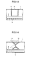
- Fig. 8 is a cross-sectional view of a cross-sectional shape of a long-side frame of a solar battery module device according to a second embodiment of the present invention.
- Fig. 9 is a cross-sectional view of a state that a second rib is selected and applied to a reinforcing frame having a smaller height than that of the reinforcing frame in the first embodiment.
- Fig. 10 is a cross-sectional view of a state that a first rib is selected and applied to a reinforcing frame having a smaller height than that of the reinforcing frame in Fig. 9 . As shown in Fig.
- a long-side frame (a first frame) 1B according to the present embodiment has a first rib 1g and a second rib 1h that extende in a direction parallel to the positioning projection 1e, between the module supporting unit 1b and the internal flange 1c.
- Other configurations are identical to those of the first embodiment.
- the first rib 1g and the second rib 1h are vertical-movement locking units, and one of these ribs is selectively used.
- the first rib 1g is cut by a width of the reinforcing frame 3, and as shown in Fig. 9 , the second rib 1h is applied to a reinforcing frame 3B having a smaller height than that of the reinforcing frame of the first embodiment.
- the first rib 1g is selected, as shown in Fig. 10 , it is applied to a reinforcing frame 3C having a smaller width than that of the reinforcing frame 3B.
- the long-side frame 1B of the solar battery module device has plural vertical-movement locking units provided at different positions in an inserting direction of the reinforcing frame 3.
- the long-side frame can be applied to plural reinforcing frames having different heights.
- Fig. 11 is a cross-sectional view of a cross-sectional shape of a long-side frame and a cross-sectional shape of a reinforcing frame of a solar battery module device according to a third embodiment of the present invention.
- a reinforcing frame 3D according to the present embodiment has side-wall surfaces 3e extended in parallel with the frame main body 3a from both-side edges of the module-side flange 3c to a back-surface direction.
- a height a of the side-wall surfaces 3e is set larger than any one of a distance b from the first rib 1g to the second rib 1h, a distance c from the second rib 1h to the positioning projection 1e, and a distance d from the internal flange 1c to the first rib 1g.
- Other configurations are identical to those of the second embodiment.
- the first rib 1g and the second rib 1h are brought into contact with the side-wall surfaces 3e of the reinforcing frame 3D, and become locking units in a horizontal direction that restrict a movement of the reinforcing frame 3D to a direction along the rack-shaped frame 10.
- the reinforcing frame 3D can be positioned more accurately.
- Fig. 12 is a cross-sectional view of a cross-sectional shape of a long-side frame and a cross-sectional shape of a reinforcing frame of a solar battery module device according to a fourth embodiment of the present invention.
- a cross-sectional shape of a reinforcing frame 3E in the present embodiment has a U shape having an opening at a back side thereof. That is, the reinforcing frame 3E has sidewall surfaces extended to a direction of a total height.
- Other configurations are identical to those of the first embodiment.
- the reinforcing frame 3E can be easily inserted into the engagement notch 1d by being guided by own sidewall surfaces. After the reinforcing frame 3E is inserted into the engagement notch 1d, the reinforcing frame 3E is brought into contact with the opening of the engagement notch 1d, and a movement of the reinforcing frame 3E to a direction along the rack-shaped frame 10 is restricted. With this arrangement, the reinforcing frame 3E can be positioned more accurately.
- Fig. 13 is a cross-sectional view of a cross-sectional shape of a reinforcing frame of a solar battery module device according to a fifth embodiment of the present invention.
- a reinforcing frame 3F in the present embodiment has a quadrangular cross-sectional shape. That is, the reinforcing frame 3F has sidewall surfaces extended to a direction of a total height.
- Other configurations are identical to those of the first embodiment.
- the solar battery module device having the above configuration can also achieve effects substantially identical to those of the fourth embodiment.
- Fig. 14 is a cross-sectional view of a cross-sectional shape of a reinforcing frame of a solar battery module device according to a sixth embodiment of the present invention.
- a reinforcing frame 3G according to the present embodiment has a cross-sectional shape connecting vertexes of two triangles by a straight line.
- the solar battery module device having the above configuration, even when a shaft center of the reinforcing frame 3G is deviated in the middle of insertion, inclined own sidewall surfaces are guided into the opening of the engagement notch 1d, and the reinforcing frame 3G can be easily inserted into the engagement notch 1d.
- the solar battery module device according to the present invention is useful for a solar battery module device installed on a construction such as a house and a building.
- the solar battery module device is suitable for a solar battery module device installed in areas having heavy snowfall or areas having severe wind and rain.
Abstract
Description
- The present invention relates to a solar battery module device installed on a construction such as a house and a building.
- Conventionally, solar battery module devices with the following configuration are used at various places and for various purposes. A transparent substrate (glass) is arranged at a light-receiving side, plural solar battery cells connected in series, or in parallel, are arranged on the back side of the transparent substrate, and the solar battery cells are then sealed with a sealing resin to constitute a solar cell module. A frame is fitted to an outer-edge portion of the solar cell module, thereby providing a solar battery module device. Bigger and bigger solar battery module devices are being manufactured in recent years with the aim to lower cost per unit output and to shorten the time required for production and line connection work. However, with an increase in the size, the load resistance performance of the surface of the transparent substrate degrades. In this solar battery module device, a predetermined strength is maintained by the transparent substrate and the frame.
- Solar battery module devices are generally installed on a construction, such as a house and a building, where they are exposed to the weather. When, for example, snow accumulates on the top surface the solar battery module device, a positive pressure that is operative to vertically press down the solar battery module device acts on the solar battery module device. On the other hand, a negative pressure that is operative to push the solar battery module device acts on the solar battery module device due to wind and the like. Because the top surface of the solar cell module, which functions as a light-receiving surface, has a wide planer structure with a large area, the module is vertically bent in a curve when receiving the positive pressure and the negative pressure.
- Various techniques have been conventionally employed to avoid breakage of the module due to downward bending thereof by the positive pressure that is operative to vertically press down the module. One such conventional technique proposes to provide a reinforcing frame on a back surface of the module. In this configuration, when the module is bent downward, the module is stopped from being bent by more than a predetermined amount, by the reinforcing frame, and thus breakage can be prevented (see, for example, Patent Document 1).
-
- Patent Document 1: Japanese Patent Application Laid-open No.
2004-6625 - To achieve cost reduction by simplifying a manufacturing process in fitting the reinforcing frame of the solar battery module device having the configuration described above, a configuration enabling the reinforcing frame to be easily fitted is conventionally desired. Furthermore, when the reinforcing frame is to be fitted to an outer-edge portion of the solar cell module by the same device (operation) as a device (operation) that arranges a rack-shaped frame, the device (operation) becomes complex. Consequently, there is a need for improvement that can solve this problem.
- Moreover, in the conventional technique, if the reinforcing frame is fixed firmly to the back surface of the solar cell module, in an event that the solar cell module is pulled upward when a negative pressure acts on the solar cell module, the back surface of the solar cell module may get separated from the reinforcing frame. Consequently, there is a need for improvement that can solve this problem. On the other hand, when the reinforcing frame is not fixed firmly to the back surface of the solar cell module, i.e., just made to come in contact with the back surface, water and/or dust get accumulated between the solar cell module and the reinforcing frame, and cause malfunction. Consequently, there is a need for improvement that can solve this problem.
- The present invention has been achieved to solve the above problems, and an object of the invention is to provide a solar battery module device to which the reinforcing frame can be easily fitted. Another object of the present invention is to provide a solar battery module device in which water and/or dust does not accumulate between the reinforcing frame and the solar battery module device so that the back surface of the solar cell module is not damaged. This is achieved by forming a gap between the solar cell module and the reinforcing frame. Still another object of the present invention is to provide a solar battery module device in which an appropriate gap can be easily formed between the solar cell module and the reinforcing frame.
- To solve the above problems and to achieve the above objects, according to an aspect of the present invention, there is provided a solar battery module device including a solar cell module formed by arranging a plurality of solar battery cells; a rack-shaped frame having a substantially rectangular shape supporting an outer-edge portion of the solar cell module by surrounding a whole periphery of the outer-edge portion; and a reinforcing frame that is bridged over between two opposite sides of the rack-shaped frame by forming a predetermined gap between the reinforcing frame and a back surface of the solar cell module, and supports the solar cell module by being brought into contact with the back surface of the solar cell module when the solar cell module is bent, wherein the reinforcing frame is engaged with engagement notches formed on the back surface of the rack-shaped frame.
- According to the present invention, because the reinforcing frame is positioned by being engaged with engagement notches formed on a back surface of a rack-shaped frame, the reinforcing frame can be easily fitted to the rack-shaped frame.
-
- [
Fig. 1] Fig. 1 is a perspective view of a state in an initial step in an assembly process of a solar battery module device according to a first embodiment of the present invention. - [
Fig. 2] Fig. 2 is a perspective view of a state that a reinforcing frame is fitted from a back side to an intermediate assembly, the intermediate assembly being an article obtained by fixing a rack-shaped frame to an outer-edge portion of a solar cell module. - [
Fig. 3] Fig. 3 is a perspective view of a state that fitting of the reinforcing frame to the intermediate assembly is completed. - [
Fig. 4] Fig. 4 is an enlarged perspective view of a portion B where the reinforcing frame is engaged with a notch of a rack-shaped frame inFig. 3 . - [
Fig. 5] Fig. 5 is a cross-sectional arrow view cut along a line A-A inFig. 1 , depicting a cross-sectional shape of a long-side frame. - [
Fig. 6] Fig. 6 is a perspective view depicting in detail the shape of the reinforcing frame. - [
Fig. 7] Fig. 7 is a cross-sectional arrow view cut along a line C-C inFig. 3 , depicting a state that a predetermined space is formed between the solar cell module and the reinforcing frame. - [
Fig. 8] Fig. 8 is a cross-sectional view of a cross-sectional shape of a long-side frame of a solar battery module device according to a second embodiment of the present invention. - [
Fig. 9] Fig. 9 is a cross-sectional view of a state that a second rib is selected and applied to a reinforcing frame having a smaller height than that of the reinforcing frame in the first embodiment. - [
Fig. 10] Fig. 10 is a cross-sectional view of a state that a first rib is selected and applied to a reinforcing frame having a smaller height than that of the reinforcing frame inFig. 9 . - [
Fig. 11] Fig. 11 is a cross-sectional view of a cross-sectional shape of a long-side frame and a cross-sectional shape of a reinforcing frame of a solar battery module device according to a third embodiment of the present invention. - [
Fig. 12] Fig. 12 is a cross-sectional view of a cross-sectional shape of a long-side frame and a cross-sectional shape of a reinforcing frame of a solar battery module device according to a fourth embodiment of the present invention. - [
Fig. 13] Fig. 13 is a cross-sectional view of a cross-sectional shape of a reinforcing frame of a solar battery module device according to a fifth embodiment of the present invention. - [
Fig. 14] Fig. 14 is a cross-sectional view of a cross-sectional shape of a reinforcing frame of a solar battery module device according to a sixth embodiment of the present invention. -
- 1, 1B
- long-side frame (first frame)
- 2
- short-side frame (second frame)
- 1a
- frame main body
- 1b
- module supporting unit
- 1c
- internal flange
- 1d
- engagement notch
- 1e
- positioning projection (vertical-movement locking unit)
- 1g
- first rib (vertical-movement locking unit, horizontal- movement locking unit)
- 1h
- second rib (vertical-movement locking unit, horizontal- movement locking unit)
- 3, 3B, 3C, 3D, 3E, 3F, 3G
- reinforcing frame
- 3a
- frame main body
- 3b
- back-surface side flange
- 3c
- module-side flange
- 3d
- end-surface screw hole
- 3e
- side-wall surface
- 7
- screw (second fixing screw)
- 10
- rack-shaped frame
- 15
- solar battery cell
- 20
- solar cell module
- 20a
- terminal box
- 20b
- cable
- H
- gap
- Exemplary embodiments of a solar battery module device according to the present invention will be explained below in detail with reference to the accompanying drawings. The present invention is not limited to the embodiments.
-
Fig. 1 is a perspective view of a state in an initial step in an assembly process of a solar battery module device according to a first embodiment of the present invention.Fig. 2 is a perspective view of a state that a reinforcing frame is fitted from a back side to an intermediate assembly, the intermediate assembly being an article obtained by fixing a rack-shaped frame to an outer-edge portion of a solar cell module.Fig. 3 is a perspective view of a state that fitting of the reinforcing frame to the intermediate assembly is completed.Fig. 4 is an enlarged perspective view of a portion B where the reinforcing frame is engaged with a notch of the rack-shaped frame inFig. 3 .Fig. 5 is a cross-sectional arrow view cut along a line A-A inFig. 1 , depicting a cross-sectional shape of a long-side frame.Fig. 6 is a perspective view depicting in detail the shape of the reinforcing frame.Fig. 7 is a cross-sectional arrow view cut along a line C-C inFig. 3 , depicting a state that a predetermined space is formed between the solar cell module and the reinforcing frame.Fig. 1 depicts a state that the solar cell module is viewed from a front side (light receiving surface) thereof. On the other hand,Figs. 2 and3 depict a state that the solar cell module is viewed from a back side thereof. - The solar battery module device includes a
solar cell module 20 of a substantially rectangular plane shape. Furthermore, a rack-shapedframe 10 of a rectangular rack shape is provided surrounding the whole periphery of an outer-edge portion of thesolar cell module 20 to support thesolar cell module 20 via the outer-edge portion. Moreover, a reinforcingframe 3 fitted to the rack-shapedframe 10. - As shown in
Fig. 1 , thesolar cell module 20 includes a plurality of series-connected or parallel-connectedsolar battery cells 15 that are arranged in a two-dimensional matrix. The whole surface of a light-receiving surface side of thesolar battery cells 15 is covered by a transparent substrate (glass). Thesolar battery cells 15 are sealed with a sealing resin. The rack-shapedframe 10 is an extrusion-molded product made of aluminum, for example, and is configured by a pair of opposite long-side frames (first frames) 1, 1, and a pair of short-side frames (second frames) 2, 2 coupled between both ends of the long-side frames side frames side frames frame 10 of a rectangular rack shape. The rack-shapedframe 10 reinforces thesolar cell module 20 and is fitted to a mount (not shown) provided on a construction such as a house and a building. The reinforcingframe 3 is fitted to the rack-shapedframe 10 from the back side of thesolar cell module 20. - As shown in
Fig. 2 ,engagement notches frame 3 are provided at central portions of back surfaces of the two long-side frames frame 3 are settled in theseengagement notches side frames frame 3 are inserted into theengagement notches solar cell module 20, and are fitted to the long-side frames Terminal boxes 20a andcables 20b, which extend from theterminal boxes 20a, are also provided on the back surface of thesolar cell module 20. - In
Fig. 3 , the reinforcingframe 3 is fitted to the rack-shapedframe 10 by being bridged over between the opposite long-side frames frame 10 as described above. In this case, as shown inFig. 4 , each end of the reinforcingframe 3 is engaged with theengagement notch 1d provided on the back surface of the long-side frame 1 and is accurately positioned. The short-side frames side frames side frames Fig. 3 . The reinforcingframe 3 is fastened by screws (second fixing screws) 7 (Fig. 7 ) (not shown) inserted into through-holes formed at central portions of the long-side frames Fig. 3 . That is, the short-side frames frame 3 are fastened by the screws (fixing screws) inserted from the same directions. - As shown in
Fig. 5 , the long-side frames side frame 1 has a plane-shaped framemain body 1a extended to a direction perpendicular to thesolar cell module 20, amodule supporting unit 1b extended from an edge of the framemain body 1a at a side of thesolar cell module 20 to the inside of the rack-shapedframe 10 and supporting thesolar cell module 20, and aninternal flange 1c formed by being extended from the framemain body 1a at an opposite side of themodule supporting unit 1b to the inside of the rack-shapedframe 10. Themodule supporting unit 1b has a cross section of a substantially U shape having an opening inside the rack-shapedframe 10, and supports the outer-edge portion of thesolar cell module 20 by holding the outer-edge portion at the inside of the U shape. - The
internal flange 1c extends in direction that is parallel to thesolar cell module 20. The rack-shapedframe 10 has theinternal flange 1c fitted to a mount (not shown), and supports thesolar cell module 20 from the mount. Theengagement notch 1d is formed by having theinternal flange 1c notched by only a width of the reinforcingframe 3. A front edge at the back side of themodule supporting unit 1b having the cross section of a substantially U shape is formed to be folded to the back side, and it is a positioning projection (a vertical-movement locking unit) 1e that positions the reinforcingframe 3 in a depth direction by being brought into contact with the reinforcingframe 3 when the reinforcingframe 3 is inserted into theengagement notch 1d. - As shown in
Fig. 6 , the reinforcingframe 3 has a substantially H shape in its cross section, and includes a plane-shaped framemain body 3a that extendes in a direction that is perpendicular to thesolar cell module 20, theback side flange 3b spread from a back-surface edge of the framemain body 3a to both sides in parallel with thesolar cell module 20, and a module-side flange 3c spread from an edge at a side of thesolar cell module 20 of the framemain body 3a to both sides in parallel with thesolar cell module 20. Two end-surface screw holes 3d are formed on an end surface of the framemain body 3a. - In
Fig. 7 , as described above, at a front end of themodule supporting unit 1b, there is provided the positioning projection (the vertical-movement locking unit) 1e that restricts a movement of the reinforcing frame to a direction of the solar cell module by being brought into contact with the reinforcingframe 3 when the reinforcingframe 3 is inserted into theengagement notch 1d. With this arrangement, the reinforcingframe 3 is arranged with a predetermined gap H between the back surface of thesolar cell module 20 and the reinforcingframe 3. Thesolar cell module 20 can experience a positive pressure as indicated by arrows F and a negative pressure as indicated by arrows G inFig. 7 , as described in the above background art. The reinforcingframe 3 supports the back surface of thesolar cell module 20 when thesolar cell module 20 is bent by a predetermined amount by the positive pressure. - As described above, in the solar battery module device of the present embodiment, because both ends of the reinforcing
frame 3 are fitted to the long-side frames engagement notches solar cell module 20, the reinforcingframe 3 can be easily fitted at a later stage to an assembly having the rack-shapedframe 10 arranged in the outer-edge portion of four sides of thesolar cell module 20. Therefore, the reinforcingframe 3 can be easily fitted at a later stage by a device (operation) different from a device (operation) that arranges the long-side frames side frames solar cell module 20. Accordingly, workability in the manufacturing process is improved. - In the solar battery module device of the present embodiment, the short-
side frames side frames side frames frame 3 is coupled to the long-side frames side frames side frames - Furthermore, in the solar battery module device of the present embodiment, the
engagement notch 1d is formed by having theinternal flange 1c of the long-side frames frame 3. The rack-shapedframe 10 has the positioning projection (the vertical-movement locking unit) 1e that restricts a movement of the reinforcingframe 3 to a direction of thesolar cell module 20 by being brought into contact with the reinforcingframe 3 inserted into theengagement notch 1d. Therefore, the gap H is formed between thesolar cell module 20 and the reinforcingframe 3. With this arrangement, the back surface of thesolar cell module 20 is not damaged, and water and/or dust do not accumulate between the reinforcingframe 3 and thesolar cell module 20. Because the reinforcingframe 3 is accurately positioned by virtue of thepositioning projection 1e, a gap in an appropriate size can be easily formed between thesolar cell module 20 and the reinforcingframe 3. - Further, in the solar battery module device of the present embodiment, the reinforcing
frame 3 has a point-symmetrical shape in a cross-sectional shape orthogonal to an axis in a longitudinal direction. Therefore, there is no directionality of upside or downside at assembling, and thus workability in the manufacturing process is improved. -
Fig. 8 is a cross-sectional view of a cross-sectional shape of a long-side frame of a solar battery module device according to a second embodiment of the present invention.Fig. 9 is a cross-sectional view of a state that a second rib is selected and applied to a reinforcing frame having a smaller height than that of the reinforcing frame in the first embodiment.Fig. 10 is a cross-sectional view of a state that a first rib is selected and applied to a reinforcing frame having a smaller height than that of the reinforcing frame inFig. 9 . As shown inFig. 8 , a long-side frame (a first frame) 1B according to the present embodiment has afirst rib 1g and asecond rib 1h that extende in a direction parallel to thepositioning projection 1e, between themodule supporting unit 1b and theinternal flange 1c. Other configurations are identical to those of the first embodiment. - The
first rib 1g and thesecond rib 1h are vertical-movement locking units, and one of these ribs is selectively used. When thesecond rib 1h is selected, thefirst rib 1g is cut by a width of the reinforcingframe 3, and as shown inFig. 9 , thesecond rib 1h is applied to a reinforcingframe 3B having a smaller height than that of the reinforcing frame of the first embodiment. When thefirst rib 1g is selected, as shown inFig. 10 , it is applied to a reinforcingframe 3C having a smaller width than that of the reinforcingframe 3B. - As described above, the long-
side frame 1B of the solar battery module device according to the present embodiment has plural vertical-movement locking units provided at different positions in an inserting direction of the reinforcingframe 3. By selecting one of the plural vertical-movement locking units, the long-side frame can be applied to plural reinforcing frames having different heights. -
Fig. 11 is a cross-sectional view of a cross-sectional shape of a long-side frame and a cross-sectional shape of a reinforcing frame of a solar battery module device according to a third embodiment of the present invention. A reinforcingframe 3D according to the present embodiment has side-wall surfaces 3e extended in parallel with the framemain body 3a from both-side edges of the module-side flange 3c to a back-surface direction. A height a of the side-wall surfaces 3e is set larger than any one of a distance b from thefirst rib 1g to thesecond rib 1h, a distance c from thesecond rib 1h to thepositioning projection 1e, and a distance d from theinternal flange 1c to thefirst rib 1g. Other configurations are identical to those of the second embodiment. - According to the solar battery module device having the above configuration, the
first rib 1g and thesecond rib 1h cut in a width of the reinforcingframe 3D guide the side-wall surfaces 3e of the reinforcingframe 3D, and facilitate insertion of the reinforcingframe 3D into theengagement notch 1d. After the reinforcingframe 3D is inserted into theengagement notch 1d, thefirst rib 1g and thesecond rib 1h are brought into contact with the side-wall surfaces 3e of the reinforcingframe 3D, and become locking units in a horizontal direction that restrict a movement of the reinforcingframe 3D to a direction along the rack-shapedframe 10. With this arrangement, the reinforcingframe 3D can be positioned more accurately. -
Fig. 12 is a cross-sectional view of a cross-sectional shape of a long-side frame and a cross-sectional shape of a reinforcing frame of a solar battery module device according to a fourth embodiment of the present invention. A cross-sectional shape of a reinforcingframe 3E in the present embodiment has a U shape having an opening at a back side thereof. That is, the reinforcingframe 3E has sidewall surfaces extended to a direction of a total height. Other configurations are identical to those of the first embodiment. - According to the solar battery module device having the above configuration, the reinforcing
frame 3E can be easily inserted into theengagement notch 1d by being guided by own sidewall surfaces. After the reinforcingframe 3E is inserted into theengagement notch 1d, the reinforcingframe 3E is brought into contact with the opening of theengagement notch 1d, and a movement of the reinforcingframe 3E to a direction along the rack-shapedframe 10 is restricted. With this arrangement, the reinforcingframe 3E can be positioned more accurately. -
Fig. 13 is a cross-sectional view of a cross-sectional shape of a reinforcing frame of a solar battery module device according to a fifth embodiment of the present invention. A reinforcingframe 3F in the present embodiment has a quadrangular cross-sectional shape. That is, the reinforcingframe 3F has sidewall surfaces extended to a direction of a total height. Other configurations are identical to those of the first embodiment. The solar battery module device having the above configuration can also achieve effects substantially identical to those of the fourth embodiment. -
Fig. 14 is a cross-sectional view of a cross-sectional shape of a reinforcing frame of a solar battery module device according to a sixth embodiment of the present invention. A reinforcingframe 3G according to the present embodiment has a cross-sectional shape connecting vertexes of two triangles by a straight line. - According to the solar battery module device having the above configuration, even when a shaft center of the reinforcing
frame 3G is deviated in the middle of insertion, inclined own sidewall surfaces are guided into the opening of theengagement notch 1d, and the reinforcingframe 3G can be easily inserted into theengagement notch 1d. - As described above, the solar battery module device according to the present invention is useful for a solar battery module device installed on a construction such as a house and a building. Particularly, the solar battery module device is suitable for a solar battery module device installed in areas having heavy snowfall or areas having severe wind and rain.
Claims (10)
- A solar battery module device comprising:a solar cell module (20) formed by arranging a plurality of solar battery cells (15);a rack-shaped frame (10) having a substantially rectangular shape supporting an outer-edge portion of the solar cell module (20) by surrounding a whole periphery of the outer-edge portion; anda reinforcing frame (3; 3B; 3C; 3D; 3E; 3F; 3G) that is bridged over between two opposite sides of the rack-shaped frame (10), and supports the solar cell module (20) by being brought into contact with a back surface of the solar cell module (20) when the solar cell module (20) is bent, wherein
notches (1d) into which the reinforcing frame (3; 3B; 3C; 3D; 3E; 3F; 3G) is inserted are provided on a back side of the rack-shaped frame (10) . - The solar battery module device according to claim 1, wherein the reinforcing frame (3; 3B; 3C; 3D; 3E; 3F; 3G) has a point-symmetrical shape in a cross-sectional shape orthogonal to an axis in a longitudinal direction.
- The solar battery module device according to claim 1 or 2, wherein the reinforcing frame (3; 3B; 3C; 3D; 3E; 3F; 3G) has a substantially H shape in cross section by a plane-shaped frame main body (3a) that extends in a direction perpendicular to the solar cell module (20) and a flange (3b, 3c) spread in parallel with the solar cell module (20) from an edge of the frame main body (3a).
- The solar battery module device according to claim 1, wherein the reinforcing frame (3E) has a cross section in a U shape by a flange (3c) spread in parallel with the solar cell module (20) and a side-wall surface that extends from an edge of the flange (3c) in a direction opposite to the solar cell module (20).
- The solar battery module device according to claim 1, wherein the reinforcing frame (3F) has a quadrangular cross-sectional shape.
- The solar battery module device according to claim 1, wherein the reinforcing frame (3G) has a cross-sectional shape including two triangles and a straight line connecting vertexes of the two triangles.
- The solar battery module device according to any one of claims 1 to 6, wherein the rack-shaped frame (10) has internal flanges (1c), and the notches (1d) are formed by having the internal flanges (1c) notched, and a width of the notches (1d) is formed by being notched by only a width of a surface of the reinforcing frame (3; 3B; 3C; 3D; 3E; 3F; 3G) parallel to the solar cell module (20).
- The solar battery module device according to any one of claims 1 to 7, further comprising a vertical-movement locking unit (1e, 1g, 1h) that is provided inside the rack-shaped frame (10) and restricts a movement of the reinforcing frame (3; 3B; 3C; 3D; 3E; 3F; 3G) to a direction of the solar cell module (20) by being brought into contact with the reinforcing frame (3; 3B; 3C; 3D; 3E; 3F; 3G).
- The solar battery module device according to claim 8, wherein
the rack-shaped frame (10) includes a supporting unit (1b) that is in contact with the back surface of the solar cell module (20), and
the vertical-movement locking unit (1e, 1g, 1h) is a projection (1e) that extends from an end of the supporting unit (1b) to an opposite side of the solar cell module (20). - The solar battery module device according to claim 8, wherein
the rack-shaped frame (10) includes a supporting unit (1b) that is in contact with the back surface of the solar cell module (20), and
the vertical-movement locking unit (1e, 1g, 1h) is a rib (1g, 1h) that is provided inside of the rack-shaped frame (10) in a direction opposite to the solar cell module (20) with respect to the supporting unit (1b).
Priority Applications (1)
| Application Number | Priority Date | Filing Date | Title |
|---|---|---|---|
| EP10001435.6A EP2228829B1 (en) | 2007-05-14 | 2007-05-14 | Solar battery module device |
Applications Claiming Priority (3)
| Application Number | Priority Date | Filing Date | Title |
|---|---|---|---|
| EP07743321.7A EP2157620B1 (en) | 2007-05-14 | 2007-05-14 | Solar battery module device |
| PCT/JP2007/059886 WO2008139610A1 (en) | 2007-05-14 | 2007-05-14 | Solar battery module device |
| EP10001435.6A EP2228829B1 (en) | 2007-05-14 | 2007-05-14 | Solar battery module device |
Related Parent Applications (5)
| Application Number | Title | Priority Date | Filing Date |
|---|---|---|---|
| EP07743321.7 Division | 2007-05-14 | ||
| WOPCT/JP2007/059886 Previously-Filed-Application | 2007-05-14 | ||
| PCT/JP2007/059886 Previously-Filed-Application WO2008139610A1 (en) | 2007-05-14 | 2007-05-14 | Solar battery module device |
| EP07743321.7A Division-Into EP2157620B1 (en) | 2007-05-14 | 2007-05-14 | Solar battery module device |
| EP07743321.7A Division EP2157620B1 (en) | 2007-05-14 | 2007-05-14 | Solar battery module device |
Publications (3)
| Publication Number | Publication Date |
|---|---|
| EP2228829A2 true EP2228829A2 (en) | 2010-09-15 |
| EP2228829A3 EP2228829A3 (en) | 2010-10-20 |
| EP2228829B1 EP2228829B1 (en) | 2016-08-24 |
Family
ID=40001840
Family Applications (2)
| Application Number | Title | Priority Date | Filing Date |
|---|---|---|---|
| EP07743321.7A Not-in-force EP2157620B1 (en) | 2007-05-14 | 2007-05-14 | Solar battery module device |
| EP10001435.6A Not-in-force EP2228829B1 (en) | 2007-05-14 | 2007-05-14 | Solar battery module device |
Family Applications Before (1)
| Application Number | Title | Priority Date | Filing Date |
|---|---|---|---|
| EP07743321.7A Not-in-force EP2157620B1 (en) | 2007-05-14 | 2007-05-14 | Solar battery module device |
Country Status (5)
| Country | Link |
|---|---|
| US (1) | US8109049B2 (en) |
| EP (2) | EP2157620B1 (en) |
| JP (1) | JP4926244B2 (en) |
| CN (1) | CN101675529B (en) |
| WO (1) | WO2008139610A1 (en) |
Cited By (1)
| Publication number | Priority date | Publication date | Assignee | Title |
|---|---|---|---|---|
| DE102011056875B4 (en) * | 2011-07-19 | 2014-04-30 | Taiwan Semiconductor Manufacturing Co., Ltd. | Solar module and method for mounting the same |
Families Citing this family (26)
| Publication number | Priority date | Publication date | Assignee | Title |
|---|---|---|---|---|
| JP4722164B2 (en) * | 2008-06-17 | 2011-07-13 | シャープ株式会社 | Solar cell module and solar cell module mount |
| US8371076B2 (en) * | 2008-08-21 | 2013-02-12 | Socore Energy Llc | Solar panel support module and method of creating array of interchangeable and substitutable solar panel support modules |
| DE102008045510A1 (en) * | 2008-09-03 | 2010-03-04 | Sapa Gmbh | Solar module frame with water drain |
| DE102009035644A1 (en) * | 2009-07-29 | 2011-02-03 | Anicca Ag | Arrangement for reduction of deflection of frame-enclosed laminates of photovoltaic modules, comprises rod-shaped component connected to frame under laminate, where sliding block is guided in rod-shaped component |
| JPWO2011039863A1 (en) * | 2009-09-30 | 2013-02-21 | 三菱重工業株式会社 | Solar panel |
| JP5230585B2 (en) * | 2009-11-24 | 2013-07-10 | 三菱電機株式会社 | Solar cell module and manufacturing method thereof |
| SG172493A1 (en) * | 2009-12-11 | 2011-07-28 | Grenzone Pte Ltd | Integrated photovoltaic roof assembly |
| US20110155127A1 (en) * | 2009-12-31 | 2011-06-30 | Du Pont Apollo Limited | Frame for solar module |
| JPWO2011090160A1 (en) | 2010-01-21 | 2013-05-23 | 京セラ株式会社 | Solar cell module |
| JP2011231477A (en) * | 2010-04-26 | 2011-11-17 | Fp Corporation Ltd | Installation structure of solar cell module |
| KR101303235B1 (en) | 2010-10-28 | 2013-09-04 | 엘지전자 주식회사 | Photovoltaic module |
| JP5867995B2 (en) | 2010-11-09 | 2016-02-24 | シャープ株式会社 | Solar cell module |
| JPWO2013061995A1 (en) * | 2011-10-24 | 2015-04-02 | 京セラ株式会社 | Solar cell module and solar cell array |
| US20130112247A1 (en) * | 2011-11-09 | 2013-05-09 | Taiwan Semiconductor Manufacturing Co. Solar, Ltd. | Frame for solar panels |
| JP2014045119A (en) * | 2012-08-28 | 2014-03-13 | Sharp Corp | Solar cell array |
| CN102623528A (en) * | 2012-04-09 | 2012-08-01 | 昆山光翼光伏科技有限公司 | Solar photovoltaic panel frame |
| US9726303B1 (en) * | 2012-09-12 | 2017-08-08 | Arlington Industries, Inc. | Rooftop conduit support |
| JP6183581B2 (en) * | 2012-09-28 | 2017-08-23 | パナソニックIpマネジメント株式会社 | Solar cell module |
| KR101969033B1 (en) * | 2012-11-20 | 2019-04-15 | 엘지전자 주식회사 | Solar cell module and photovoltaic power generation system including the same |
| JP6250932B2 (en) * | 2013-01-11 | 2017-12-20 | シャープ株式会社 | Solar cell module and mounting structure for solar cell module |
| US20140318605A1 (en) * | 2013-04-30 | 2014-10-30 | Northern States Metals Company | Panel rack support and protective system for stacking |
| DE102013211167A1 (en) * | 2013-06-14 | 2014-12-18 | SolarWorld Industries Thüringen GmbH | Solar module frame with a stabilizing rail, solar module with a solar module frame with a stabilizing rail and connection unit for a solar module frame |
| TWI505631B (en) * | 2014-06-20 | 2015-10-21 | Neo Solar Power Corp | Frame of solar module |
| CN104935247B (en) * | 2015-06-19 | 2018-02-27 | 苏州腾晖光伏技术有限公司 | A kind of high mechanical load light weight solar battery component |
| GB2563046A (en) | 2017-06-01 | 2018-12-05 | Rec Solar Pte Ltd | Cost effective frame design for thinner wafers |
| CN108923739A (en) * | 2018-10-16 | 2018-11-30 | 苏州金山太阳能科技有限公司 | A kind of anchor structure of the photovoltaic panel of solar tracking device |
Citations (1)
| Publication number | Priority date | Publication date | Assignee | Title |
|---|---|---|---|---|
| JP2004006625A (en) | 2002-03-27 | 2004-01-08 | Kyocera Corp | Solar cell module and solar cell array |
Family Cites Families (14)
| Publication number | Priority date | Publication date | Assignee | Title |
|---|---|---|---|---|
| FR2350695A1 (en) * | 1976-05-03 | 1977-12-02 | Aerospatiale | SOLAR ELECTRIC ENERGY GENERATOR |
| US4172739A (en) * | 1977-12-27 | 1979-10-30 | Solar Homes, Inc. | Sun tracker with dual axis support for diurnal movement and seasonal adjustment |
| JP3457783B2 (en) | 1995-11-28 | 2003-10-20 | シャープ株式会社 | Solar cell module and its mounting structure |
| JP3674234B2 (en) | 1997-04-18 | 2005-07-20 | 株式会社カネカ | Large solar cell module |
| JPH10308522A (en) * | 1997-05-01 | 1998-11-17 | Kanegafuchi Chem Ind Co Ltd | Frame for solar cell module |
| US7012188B2 (en) * | 2000-04-04 | 2006-03-14 | Peter Stuart Erling | Framing system for solar panels |
| JP2003031833A (en) | 2001-07-11 | 2003-01-31 | Sekisui Chem Co Ltd | Solar cell module |
| JP2004165556A (en) * | 2002-11-15 | 2004-06-10 | Mitsubishi Heavy Ind Ltd | Solar cell module and supporting body structure provided therein |
| JP2005150318A (en) | 2003-11-14 | 2005-06-09 | Canon Inc | Solar cell module and its manufacturing method |
| CN101138097B (en) | 2005-03-18 | 2010-10-13 | 京瓷株式会社 | Solar cell module and solar cell array |
| JP2006278537A (en) | 2005-03-28 | 2006-10-12 | Kyocera Corp | Solar battery array |
| DE102005014320A1 (en) * | 2005-03-30 | 2006-10-12 | Gümpelein, Manuela | Tracking device for a photovoltaic system |
| CN100424305C (en) * | 2005-07-20 | 2008-10-08 | 常州天合光能有限公司 | General photovoltaic building member |
| CN101669212B (en) * | 2007-05-14 | 2012-11-28 | 三菱电机株式会社 | Solar battery module device |
-
2007
- 2007-05-14 US US12/599,868 patent/US8109049B2/en not_active Expired - Fee Related
- 2007-05-14 EP EP07743321.7A patent/EP2157620B1/en not_active Not-in-force
- 2007-05-14 JP JP2009513943A patent/JP4926244B2/en not_active Expired - Fee Related
- 2007-05-14 WO PCT/JP2007/059886 patent/WO2008139610A1/en active Application Filing
- 2007-05-14 CN CN2007800529719A patent/CN101675529B/en not_active Expired - Fee Related
- 2007-05-14 EP EP10001435.6A patent/EP2228829B1/en not_active Not-in-force
Patent Citations (1)
| Publication number | Priority date | Publication date | Assignee | Title |
|---|---|---|---|---|
| JP2004006625A (en) | 2002-03-27 | 2004-01-08 | Kyocera Corp | Solar cell module and solar cell array |
Cited By (2)
| Publication number | Priority date | Publication date | Assignee | Title |
|---|---|---|---|---|
| DE102011056875B4 (en) * | 2011-07-19 | 2014-04-30 | Taiwan Semiconductor Manufacturing Co., Ltd. | Solar module and method for mounting the same |
| US8875394B2 (en) | 2011-07-19 | 2014-11-04 | Taiwan Semiconductor Manufacturing Co., Ltd. | Solar energy collecting modules and method for assembling the same |
Also Published As
| Publication number | Publication date |
|---|---|
| JPWO2008139610A1 (en) | 2010-07-29 |
| US8109049B2 (en) | 2012-02-07 |
| US20100218810A1 (en) | 2010-09-02 |
| CN101675529A (en) | 2010-03-17 |
| EP2157620B1 (en) | 2016-12-21 |
| WO2008139610A1 (en) | 2008-11-20 |
| EP2228829A3 (en) | 2010-10-20 |
| CN101675529B (en) | 2013-05-01 |
| EP2157620A4 (en) | 2010-10-20 |
| EP2228829B1 (en) | 2016-08-24 |
| EP2157620A1 (en) | 2010-02-24 |
| JP4926244B2 (en) | 2012-05-09 |
Similar Documents
| Publication | Publication Date | Title |
|---|---|---|
| EP2228829B1 (en) | Solar battery module device | |
| JP5295436B2 (en) | Mounting member and solar cell array using the same | |
| EP2597682B1 (en) | Solar cell array | |
| US8316591B2 (en) | Solar cell module device | |
| JP6034427B2 (en) | Solar array | |
| US7694466B2 (en) | Solar cell unit attaching apparatus | |
| US8273981B2 (en) | Structure for securing solar cell modules and frame and securing member for solar cell modules | |
| US9188365B2 (en) | Frame for supporting solar module | |
| TWI487873B (en) | Solar apparatus and mounting system thereof | |
| JP5235395B2 (en) | Solar cell module | |
| JP5159832B2 (en) | Solar cell module device | |
| JP2011114035A (en) | Solar cell module and manufacturing method thereof | |
| EP2341554A2 (en) | Solar panel tile structure and combination thereof | |
| JP6350859B2 (en) | Solar power plant | |
| JP6449006B2 (en) | Roof structure | |
| JP5574930B2 (en) | Solar array | |
| JP6594626B2 (en) | Roof structure | |
| JP5456188B2 (en) | Solar cell module | |
| JP2020041309A (en) | Solar cell module mounting instrument and solar power device | |
| JP2015180171A (en) | solar cell module |
Legal Events
| Date | Code | Title | Description |
|---|---|---|---|
| PUAI | Public reference made under article 153(3) epc to a published international application that has entered the european phase |
Free format text: ORIGINAL CODE: 0009012 |
|
| AC | Divisional application: reference to earlier application |
Ref document number: 2157620 Country of ref document: EP Kind code of ref document: P |
|
| AK | Designated contracting states |
Kind code of ref document: A2 Designated state(s): AT BE BG CH CY CZ DE DK EE ES FI FR GB GR HU IE IS IT LI LT LU LV MC MT NL PL PT RO SE SI SK TR |
|
| PUAL | Search report despatched |
Free format text: ORIGINAL CODE: 0009013 |
|
| AK | Designated contracting states |
Kind code of ref document: A3 Designated state(s): AT BE BG CH CY CZ DE DK EE ES FI FR GB GR HU IE IS IT LI LT LU LV MC MT NL PL PT RO SE SI SK TR |
|
| 17P | Request for examination filed |
Effective date: 20110418 |
|
| 17Q | First examination report despatched |
Effective date: 20110725 |
|
| RIC1 | Information provided on ipc code assigned before grant |
Ipc: H02S 30/10 20140101ALI20150715BHEP Ipc: F24J 2/52 20060101AFI20150715BHEP |
|
| REG | Reference to a national code |
Ref country code: DE Ref legal event code: R079 Ref document number: 602007047661 Country of ref document: DE Free format text: PREVIOUS MAIN CLASS: H01L0031042000 Ipc: F24J0002520000 |
|
| GRAP | Despatch of communication of intention to grant a patent |
Free format text: ORIGINAL CODE: EPIDOSNIGR1 |
|
| RIC1 | Information provided on ipc code assigned before grant |
Ipc: F24J 2/52 20060101AFI20160118BHEP |
|
| INTG | Intention to grant announced |
Effective date: 20160209 |
|
| GRAS | Grant fee paid |
Free format text: ORIGINAL CODE: EPIDOSNIGR3 |
|
| GRAA | (expected) grant |
Free format text: ORIGINAL CODE: 0009210 |
|
| AC | Divisional application: reference to earlier application |
Ref document number: 2157620 Country of ref document: EP Kind code of ref document: P |
|
| AK | Designated contracting states |
Kind code of ref document: B1 Designated state(s): AT BE BG CH CY CZ DE DK EE ES FI FR GB GR HU IE IS IT LI LT LU LV MC MT NL PL PT RO SE SI SK TR |
|
| REG | Reference to a national code |
Ref country code: GB Ref legal event code: FG4D |
|
| REG | Reference to a national code |
Ref country code: CH Ref legal event code: EP |
|
| REG | Reference to a national code |
Ref country code: AT Ref legal event code: REF Ref document number: 823470 Country of ref document: AT Kind code of ref document: T Effective date: 20160915 |
|
| REG | Reference to a national code |
Ref country code: IE Ref legal event code: FG4D |
|
| REG | Reference to a national code |
Ref country code: DE Ref legal event code: R096 Ref document number: 602007047661 Country of ref document: DE |
|
| REG | Reference to a national code |
Ref country code: LT Ref legal event code: MG4D |
|
| REG | Reference to a national code |
Ref country code: NL Ref legal event code: MP Effective date: 20160824 |
|
| REG | Reference to a national code |
Ref country code: AT Ref legal event code: MK05 Ref document number: 823470 Country of ref document: AT Kind code of ref document: T Effective date: 20160824 |
|
| PG25 | Lapsed in a contracting state [announced via postgrant information from national office to epo] |
Ref country code: IT Free format text: LAPSE BECAUSE OF FAILURE TO SUBMIT A TRANSLATION OF THE DESCRIPTION OR TO PAY THE FEE WITHIN THE PRESCRIBED TIME-LIMIT Effective date: 20160824 Ref country code: LT Free format text: LAPSE BECAUSE OF FAILURE TO SUBMIT A TRANSLATION OF THE DESCRIPTION OR TO PAY THE FEE WITHIN THE PRESCRIBED TIME-LIMIT Effective date: 20160824 Ref country code: NL Free format text: LAPSE BECAUSE OF FAILURE TO SUBMIT A TRANSLATION OF THE DESCRIPTION OR TO PAY THE FEE WITHIN THE PRESCRIBED TIME-LIMIT Effective date: 20160824 Ref country code: FI Free format text: LAPSE BECAUSE OF FAILURE TO SUBMIT A TRANSLATION OF THE DESCRIPTION OR TO PAY THE FEE WITHIN THE PRESCRIBED TIME-LIMIT Effective date: 20160824 |
|
| PG25 | Lapsed in a contracting state [announced via postgrant information from national office to epo] |
Ref country code: LV Free format text: LAPSE BECAUSE OF FAILURE TO SUBMIT A TRANSLATION OF THE DESCRIPTION OR TO PAY THE FEE WITHIN THE PRESCRIBED TIME-LIMIT Effective date: 20160824 Ref country code: SE Free format text: LAPSE BECAUSE OF FAILURE TO SUBMIT A TRANSLATION OF THE DESCRIPTION OR TO PAY THE FEE WITHIN THE PRESCRIBED TIME-LIMIT Effective date: 20160824 Ref country code: GR Free format text: LAPSE BECAUSE OF FAILURE TO SUBMIT A TRANSLATION OF THE DESCRIPTION OR TO PAY THE FEE WITHIN THE PRESCRIBED TIME-LIMIT Effective date: 20161125 Ref country code: AT Free format text: LAPSE BECAUSE OF FAILURE TO SUBMIT A TRANSLATION OF THE DESCRIPTION OR TO PAY THE FEE WITHIN THE PRESCRIBED TIME-LIMIT Effective date: 20160824 Ref country code: ES Free format text: LAPSE BECAUSE OF FAILURE TO SUBMIT A TRANSLATION OF THE DESCRIPTION OR TO PAY THE FEE WITHIN THE PRESCRIBED TIME-LIMIT Effective date: 20160824 Ref country code: PT Free format text: LAPSE BECAUSE OF FAILURE TO SUBMIT A TRANSLATION OF THE DESCRIPTION OR TO PAY THE FEE WITHIN THE PRESCRIBED TIME-LIMIT Effective date: 20161226 |
|
| PG25 | Lapsed in a contracting state [announced via postgrant information from national office to epo] |
Ref country code: EE Free format text: LAPSE BECAUSE OF FAILURE TO SUBMIT A TRANSLATION OF THE DESCRIPTION OR TO PAY THE FEE WITHIN THE PRESCRIBED TIME-LIMIT Effective date: 20160824 Ref country code: RO Free format text: LAPSE BECAUSE OF FAILURE TO SUBMIT A TRANSLATION OF THE DESCRIPTION OR TO PAY THE FEE WITHIN THE PRESCRIBED TIME-LIMIT Effective date: 20160824 |
|
| REG | Reference to a national code |
Ref country code: DE Ref legal event code: R097 Ref document number: 602007047661 Country of ref document: DE |
|
| PG25 | Lapsed in a contracting state [announced via postgrant information from national office to epo] |
Ref country code: DK Free format text: LAPSE BECAUSE OF FAILURE TO SUBMIT A TRANSLATION OF THE DESCRIPTION OR TO PAY THE FEE WITHIN THE PRESCRIBED TIME-LIMIT Effective date: 20160824 Ref country code: CZ Free format text: LAPSE BECAUSE OF FAILURE TO SUBMIT A TRANSLATION OF THE DESCRIPTION OR TO PAY THE FEE WITHIN THE PRESCRIBED TIME-LIMIT Effective date: 20160824 Ref country code: BE Free format text: LAPSE BECAUSE OF FAILURE TO SUBMIT A TRANSLATION OF THE DESCRIPTION OR TO PAY THE FEE WITHIN THE PRESCRIBED TIME-LIMIT Effective date: 20160824 Ref country code: PL Free format text: LAPSE BECAUSE OF FAILURE TO SUBMIT A TRANSLATION OF THE DESCRIPTION OR TO PAY THE FEE WITHIN THE PRESCRIBED TIME-LIMIT Effective date: 20160824 Ref country code: BG Free format text: LAPSE BECAUSE OF FAILURE TO SUBMIT A TRANSLATION OF THE DESCRIPTION OR TO PAY THE FEE WITHIN THE PRESCRIBED TIME-LIMIT Effective date: 20161124 Ref country code: SK Free format text: LAPSE BECAUSE OF FAILURE TO SUBMIT A TRANSLATION OF THE DESCRIPTION OR TO PAY THE FEE WITHIN THE PRESCRIBED TIME-LIMIT Effective date: 20160824 |
|
| PLBE | No opposition filed within time limit |
Free format text: ORIGINAL CODE: 0009261 |
|
| STAA | Information on the status of an ep patent application or granted ep patent |
Free format text: STATUS: NO OPPOSITION FILED WITHIN TIME LIMIT |
|
| 26N | No opposition filed |
Effective date: 20170526 |
|
| PG25 | Lapsed in a contracting state [announced via postgrant information from national office to epo] |
Ref country code: LU Free format text: LAPSE BECAUSE OF NON-PAYMENT OF DUE FEES Effective date: 20170531 Ref country code: SI Free format text: LAPSE BECAUSE OF FAILURE TO SUBMIT A TRANSLATION OF THE DESCRIPTION OR TO PAY THE FEE WITHIN THE PRESCRIBED TIME-LIMIT Effective date: 20160824 |
|
| REG | Reference to a national code |
Ref country code: DE Ref legal event code: R079 Ref document number: 602007047661 Country of ref document: DE Free format text: PREVIOUS MAIN CLASS: F24J0002520000 Ipc: F24S0025000000 |
|
| REG | Reference to a national code |
Ref country code: CH Ref legal event code: PL |
|
| GBPC | Gb: european patent ceased through non-payment of renewal fee |
Effective date: 20170514 |
|
| PG25 | Lapsed in a contracting state [announced via postgrant information from national office to epo] |
Ref country code: MC Free format text: LAPSE BECAUSE OF FAILURE TO SUBMIT A TRANSLATION OF THE DESCRIPTION OR TO PAY THE FEE WITHIN THE PRESCRIBED TIME-LIMIT Effective date: 20160824 |
|
| REG | Reference to a national code |
Ref country code: IE Ref legal event code: MM4A |
|
| PG25 | Lapsed in a contracting state [announced via postgrant information from national office to epo] |
Ref country code: LI Free format text: LAPSE BECAUSE OF NON-PAYMENT OF DUE FEES Effective date: 20170531 Ref country code: CH Free format text: LAPSE BECAUSE OF NON-PAYMENT OF DUE FEES Effective date: 20170531 |
|
| REG | Reference to a national code |
Ref country code: FR Ref legal event code: ST Effective date: 20180131 |
|
| PG25 | Lapsed in a contracting state [announced via postgrant information from national office to epo] |
Ref country code: LU Free format text: LAPSE BECAUSE OF NON-PAYMENT OF DUE FEES Effective date: 20170514 |
|
| PG25 | Lapsed in a contracting state [announced via postgrant information from national office to epo] |
Ref country code: IE Free format text: LAPSE BECAUSE OF NON-PAYMENT OF DUE FEES Effective date: 20170514 Ref country code: GB Free format text: LAPSE BECAUSE OF NON-PAYMENT OF DUE FEES Effective date: 20170514 |
|
| PG25 | Lapsed in a contracting state [announced via postgrant information from national office to epo] |
Ref country code: FR Free format text: LAPSE BECAUSE OF NON-PAYMENT OF DUE FEES Effective date: 20170531 |
|
| PG25 | Lapsed in a contracting state [announced via postgrant information from national office to epo] |
Ref country code: MT Free format text: LAPSE BECAUSE OF NON-PAYMENT OF DUE FEES Effective date: 20170514 |
|
| REG | Reference to a national code |
Ref country code: DE Ref legal event code: R084 Ref document number: 602007047661 Country of ref document: DE |
|
| PG25 | Lapsed in a contracting state [announced via postgrant information from national office to epo] |
Ref country code: HU Free format text: LAPSE BECAUSE OF FAILURE TO SUBMIT A TRANSLATION OF THE DESCRIPTION OR TO PAY THE FEE WITHIN THE PRESCRIBED TIME-LIMIT; INVALID AB INITIO Effective date: 20070514 |
|
| PG25 | Lapsed in a contracting state [announced via postgrant information from national office to epo] |
Ref country code: CY Free format text: LAPSE BECAUSE OF NON-PAYMENT OF DUE FEES Effective date: 20160824 |
|
| PG25 | Lapsed in a contracting state [announced via postgrant information from national office to epo] |
Ref country code: TR Free format text: LAPSE BECAUSE OF FAILURE TO SUBMIT A TRANSLATION OF THE DESCRIPTION OR TO PAY THE FEE WITHIN THE PRESCRIBED TIME-LIMIT Effective date: 20160824 |
|
| PG25 | Lapsed in a contracting state [announced via postgrant information from national office to epo] |
Ref country code: IS Free format text: LAPSE BECAUSE OF FAILURE TO SUBMIT A TRANSLATION OF THE DESCRIPTION OR TO PAY THE FEE WITHIN THE PRESCRIBED TIME-LIMIT Effective date: 20161224 |
|
| PGFP | Annual fee paid to national office [announced via postgrant information from national office to epo] |
Ref country code: DE Payment date: 20200428 Year of fee payment: 14 |
|
| REG | Reference to a national code |
Ref country code: DE Ref legal event code: R119 Ref document number: 602007047661 Country of ref document: DE |
|
| PG25 | Lapsed in a contracting state [announced via postgrant information from national office to epo] |
Ref country code: DE Free format text: LAPSE BECAUSE OF NON-PAYMENT OF DUE FEES Effective date: 20211201 |