EP2228607A2 - Controlled mechanical ventilation box with changeable direction inlet ports and outlet ports - Google Patents
Controlled mechanical ventilation box with changeable direction inlet ports and outlet ports Download PDFInfo
- Publication number
- EP2228607A2 EP2228607A2 EP10152976A EP10152976A EP2228607A2 EP 2228607 A2 EP2228607 A2 EP 2228607A2 EP 10152976 A EP10152976 A EP 10152976A EP 10152976 A EP10152976 A EP 10152976A EP 2228607 A2 EP2228607 A2 EP 2228607A2
- Authority
- EP
- European Patent Office
- Prior art keywords
- nozzles
- openings
- controlled mechanical
- mechanical ventilation
- coupling
- Prior art date
- Legal status (The legal status is an assumption and is not a legal conclusion. Google has not performed a legal analysis and makes no representation as to the accuracy of the status listed.)
- Granted
Links
Images




Classifications
-
- F—MECHANICAL ENGINEERING; LIGHTING; HEATING; WEAPONS; BLASTING
- F24—HEATING; RANGES; VENTILATING
- F24F—AIR-CONDITIONING; AIR-HUMIDIFICATION; VENTILATION; USE OF AIR CURRENTS FOR SCREENING
- F24F7/00—Ventilation
- F24F7/04—Ventilation with ducting systems, e.g. by double walls; with natural circulation
- F24F7/06—Ventilation with ducting systems, e.g. by double walls; with natural circulation with forced air circulation, e.g. by fan positioning of a ventilator in or against a conduit
-
- F—MECHANICAL ENGINEERING; LIGHTING; HEATING; WEAPONS; BLASTING
- F24—HEATING; RANGES; VENTILATING
- F24F—AIR-CONDITIONING; AIR-HUMIDIFICATION; VENTILATION; USE OF AIR CURRENTS FOR SCREENING
- F24F13/00—Details common to, or for air-conditioning, air-humidification, ventilation or use of air currents for screening
- F24F13/02—Ducting arrangements
- F24F13/0209—Ducting arrangements characterised by their connecting means, e.g. flanges
-
- F—MECHANICAL ENGINEERING; LIGHTING; HEATING; WEAPONS; BLASTING
- F24—HEATING; RANGES; VENTILATING
- F24F—AIR-CONDITIONING; AIR-HUMIDIFICATION; VENTILATION; USE OF AIR CURRENTS FOR SCREENING
- F24F13/00—Details common to, or for air-conditioning, air-humidification, ventilation or use of air currents for screening
- F24F13/02—Ducting arrangements
- F24F13/0236—Ducting arrangements with ducts including air distributors, e.g. air collecting boxes with at least three openings
-
- F—MECHANICAL ENGINEERING; LIGHTING; HEATING; WEAPONS; BLASTING
- F24—HEATING; RANGES; VENTILATING
- F24F—AIR-CONDITIONING; AIR-HUMIDIFICATION; VENTILATION; USE OF AIR CURRENTS FOR SCREENING
- F24F13/00—Details common to, or for air-conditioning, air-humidification, ventilation or use of air currents for screening
- F24F13/20—Casings or covers
-
- F—MECHANICAL ENGINEERING; LIGHTING; HEATING; WEAPONS; BLASTING
- F24—HEATING; RANGES; VENTILATING
- F24F—AIR-CONDITIONING; AIR-HUMIDIFICATION; VENTILATION; USE OF AIR CURRENTS FOR SCREENING
- F24F7/00—Ventilation
- F24F2007/001—Ventilation with exhausting air ducts
- F24F2007/002—Junction box, e.g. for ducts from kitchen, toilet or bathroom
Definitions
- the present invention relates to the controlled mechanical ventilation of homes proposing a device for this purpose, with a structural configuration which improves the assembly characteristics and offers installation versatility for several installation forms.
- CMV controlled mechanical ventilation
- nozzles are arranged for the connection of tubular ducts for communication with the rooms to be ventilated, such as the kitchen, bathrooms and other moist areas of homes, for the purpose of extracting the air from these rooms towards the discharge opening of the CMV unit, which is established in connection, by means of a duct, with an outlet for evacuating the air from the ventilation through the roof of the building.
- CMV controlled mechanical ventilation
- the device object of the invention is formed by a CMV unit, which is provided with a discharge outlet having two selective openings directed in two directions and multiple intake openings for extracting the air from the rooms to be ventilated and making it circulate to the evacuation outlet to the exterior of the building, nozzles being coupled on said intake and discharge openings, which nozzles incorporate flexible flanges integral therewith for clamping the coupling of the connection of said nozzles with the respective tubular ducts of the ventilation installation.
- the nozzles of the intake openings of the device are susceptible of being directed selectively, in this case, according to the assembly arrangement required by the application site, said nozzles being able to be placed in the assembly on the device, according to at least two arrangements of orientation at 90 degrees to one another, which allows adapting to different installation variants of the device.
- said nozzles of the intake openings determine a coupling formation on the structural body of the device according to an inclined coupling face in combination with a seat around the intake openings of the structural body of the device also in an inclined position, such that said nozzles of the intake openings can be arranged in respective perpendicular positions of orientation in the assembly on the structural body of the device, according to what is required for the application installation.
- the discharge openings are in turn defined in two perpendicular orientations, so that, depending on the installation required from the device, for example horizontally in a false ceiling, or vertically on a wall, the opening of one of the orientations is shut, and a nozzle is arranged in the opening of the other orientation for the connection coupling of the corresponding tubular duct towards the evacuation outlet of the air of the ventilation installation.
- the device of the invention has certainly advantageous features, acquiring its own identity and preferred nature of application with respect to conventional controlled mechanical ventilation systems in houses or single family type homes.
- the object of the invention relates to a controlled mechanical ventilation device for use in single family homes or the like, of the type comprising a controlled mechanical ventilation (CMV) unit (1) from which tubular ducts (2) for connection with the enclosed areas or rooms to be ventilated are established, as well as a connection for conducting the air of the ventilation to an evacuation outlet through the roof of the building.
- CMV controlled mechanical ventilation
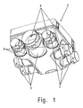
- FIG. 1 shows an embodiment of the CMV unit (1) according to the object of the invention, which is provided with a discharge outlet having two openings (3) directed in two directions and multiple intake openings (4), respective nozzles (5 and 6) being coupled on said openings (3 and 4) for the coupling of the corresponding ducts (2) in the application installation.
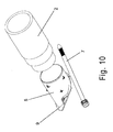
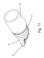
- Said nozzles (5 and 6) have flanges (7) integral therewith, as is shown in Figure 9 , for clamping with said flanges (7) the coupling of these nozzles (5 and 6) with the respective tubular ducts (2) in the application installation of the device, according to what is observed in Figures 10 and 11 .
- the mentioned flanges (7) are provided structurally formed with an elastomeric material, for the purpose of reducing the vibrations produced in the operation of the ventilation device.
- the nozzles (5) which are arranged in the intake openings (4) are susceptible of being placed in two different arrangements of orientation at 90 degrees, so that the air inlet through the mentioned intake openings (4) can be established from a lower position or from a side of the device.
- said nozzles (5) of the intake openings (4) have a coupling formation (9) defined with an inclined face for the coupling on the structural body of the CMV unit (1), whereas in relation to the openings (4) said body of the CMV unit (1) determines a seat also inclined, such that, by means of the combination of the inclinations of the coupling formation (9) of the nozzles (5) and of the seat of the coupling with respect to the openings (4) of the structural body of the CMV unit (1), the mentioned nozzles (5) can be placed in a vertical orientation or in a horizontal orientation.
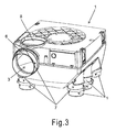
- the openings (3) of the discharge outlet are defined where appropriate according to two perpendicular directions, towards the side and towards the upper part, in the structural body of the CMV unit (1), thereby the air outlet of the device can be established on the side or on the upper part, a nozzle (6) being incorporated in each case on the opening (3) of the direction of interest and shutting the other opening (3) by means of a cover (8), as is observed in Figures 3 and 4 .
- This device of the invention therefore allows arranging the air inlets and outlets in the CMV unit (1) according to the convenient orientation in each case for the assembly of the application installation, thus enabling a very advantageous adaptation depending on the circumstances of each case, to facilitate the assembly of the application installation, the nozzles (5) being arranged on the intake openings (4), in the vertical position or in the horizontal position, or in combinations of both positions, i.e., with the nozzles (5) of openings (4) in the vertical position and the others in the horizontal position, and at the same time the air outlet can be established on the side or on the upper part of the body of the CMV unit (1), as well as in a combination of any of these air outlet arrangements, with any of the combinations of position of the nozzles (5) in the intake openings (4).
- the arrangement of the nozzles (5) on the openings (4) of the structural body of the CMV unit (1) can be also determined with other solutions of the assembly coupling, for example with a coupling in the form of ball-and-socket joint, without the concept being altered by it.
Landscapes
- Engineering & Computer Science (AREA)
- Chemical & Material Sciences (AREA)
- Combustion & Propulsion (AREA)
- Mechanical Engineering (AREA)
- General Engineering & Computer Science (AREA)
- Air-Flow Control Members (AREA)
- Ventilation (AREA)
Abstract
Description
- The present invention relates to the controlled mechanical ventilation of homes proposing a device for this purpose, with a structural configuration which improves the assembly characteristics and offers installation versatility for several installation forms.
- The use of controlled mechanical ventilation (CMV) units, which are formed by a frame which has intake openings and a discharge opening, a ventilator being housed inside the unit to force the circulation of air through the ventilation installation, is known in the ventilation of single family homes.
- With respect to the openings of the CMV unit, nozzles are arranged for the connection of tubular ducts for communication with the rooms to be ventilated, such as the kitchen, bathrooms and other moist areas of homes, for the purpose of extracting the air from these rooms towards the discharge opening of the CMV unit, which is established in connection, by means of a duct, with an outlet for evacuating the air from the ventilation through the roof of the building.
- Conventional controlled mechanical ventilation (CMV) units incorporate nozzles of the intake and discharge openings, arranged in a fixed orientation, which conditions the assembly for the installation, making placement difficult in some cases, due to the fact that this type of device is usually arranged in false ceilings, attics, or similar locations, where the space can be limited.
- According to the present invention a controlled mechanical ventilation device, developed with constructive and functional features which simplify and facilitate the practical installation tasks for the application, satisfactorily solving the drawbacks of conventional solutions for these ventilation systems, is proposed.
- The device object of the invention is formed by a CMV unit, which is provided with a discharge outlet having two selective openings directed in two directions and multiple intake openings for extracting the air from the rooms to be ventilated and making it circulate to the evacuation outlet to the exterior of the building, nozzles being coupled on said intake and discharge openings, which nozzles incorporate flexible flanges integral therewith for clamping the coupling of the connection of said nozzles with the respective tubular ducts of the ventilation installation.
- The nozzles of the intake openings of the device are susceptible of being directed selectively, in this case, according to the assembly arrangement required by the application site, said nozzles being able to be placed in the assembly on the device, according to at least two arrangements of orientation at 90 degrees to one another, which allows adapting to different installation variants of the device.
- To that end, said nozzles of the intake openings determine a coupling formation on the structural body of the device according to an inclined coupling face in combination with a seat around the intake openings of the structural body of the device also in an inclined position, such that said nozzles of the intake openings can be arranged in respective perpendicular positions of orientation in the assembly on the structural body of the device, according to what is required for the application installation.
- The discharge openings are in turn defined in two perpendicular orientations, so that, depending on the installation required from the device, for example horizontally in a false ceiling, or vertically on a wall, the opening of one of the orientations is shut, and a nozzle is arranged in the opening of the other orientation for the connection coupling of the corresponding tubular duct towards the evacuation outlet of the air of the ventilation installation.
- Therefore, the device of the invention has certainly advantageous features, acquiring its own identity and preferred nature of application with respect to conventional controlled mechanical ventilation systems in houses or single family type homes.
-
-
Figure 1 shows a bottom perspective view of the device of the invention, with the intake nozzles in a horizontal assembly arrangement. -
Figure 2 is a bottom perspective view of the device with the intake nozzles in a vertical assembly arrangement. -
Figure 3 shows a top perspective view of the device, the discharge outlet being observed with a vertical and another horizontal opening, incorporating a cover in the first one and a nozzle in the second one. -
Figure 4 is a perspective view like the previous one, with the discharge openings in reverse arrangement. -
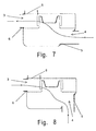
Figures 5 to 8 show schemes of the operation modes of the device depending on the different positions of the nozzles in the intake and discharge openings. -
Figure 9 is a detailed perspective view of the intake openings of the device. -
Figure 10 is an exploded perspective view of the nozzle of the previous figure in relation to a coupling tubular duct. -
Figure 11 shows a perspective view of the assembly of the previous figure assembled. - The object of the invention relates to a controlled mechanical ventilation device for use in single family homes or the like, of the type comprising a controlled mechanical ventilation (CMV) unit (1) from which tubular ducts (2) for connection with the enclosed areas or rooms to be ventilated are established, as well as a connection for conducting the air of the ventilation to an evacuation outlet through the roof of the building.
-
Figure 1 shows an embodiment of the CMV unit (1) according to the object of the invention, which is provided with a discharge outlet having two openings (3) directed in two directions and multiple intake openings (4), respective nozzles (5 and 6) being coupled on said openings (3 and 4) for the coupling of the corresponding ducts (2) in the application installation. - Said nozzles (5 and 6) have flanges (7) integral therewith, as is shown in
Figure 9 , for clamping with said flanges (7) the coupling of these nozzles (5 and 6) with the respective tubular ducts (2) in the application installation of the device, according to what is observed inFigures 10 and11 . In relation to the purpose for which they are intended, the mentioned flanges (7) are provided structurally formed with an elastomeric material, for the purpose of reducing the vibrations produced in the operation of the ventilation device. - As is observed in
Figures 1 and2 , the nozzles (5) which are arranged in the intake openings (4) are susceptible of being placed in two different arrangements of orientation at 90 degrees, so that the air inlet through the mentioned intake openings (4) can be established from a lower position or from a side of the device. - To that end, said nozzles (5) of the intake openings (4) have a coupling formation (9) defined with an inclined face for the coupling on the structural body of the CMV unit (1), whereas in relation to the openings (4) said body of the CMV unit (1) determines a seat also inclined, such that, by means of the combination of the inclinations of the coupling formation (9) of the nozzles (5) and of the seat of the coupling with respect to the openings (4) of the structural body of the CMV unit (1), the mentioned nozzles (5) can be placed in a vertical orientation or in a horizontal orientation.
- The openings (3) of the discharge outlet are defined where appropriate according to two perpendicular directions, towards the side and towards the upper part, in the structural body of the CMV unit (1), thereby the air outlet of the device can be established on the side or on the upper part, a nozzle (6) being incorporated in each case on the opening (3) of the direction of interest and shutting the other opening (3) by means of a cover (8), as is observed in
Figures 3 and4 . - This device of the invention therefore allows arranging the air inlets and outlets in the CMV unit (1) according to the convenient orientation in each case for the assembly of the application installation, thus enabling a very advantageous adaptation depending on the circumstances of each case, to facilitate the assembly of the application installation, the nozzles (5) being arranged on the intake openings (4), in the vertical position or in the horizontal position, or in combinations of both positions, i.e., with the nozzles (5) of openings (4) in the vertical position and the others in the horizontal position, and at the same time the air outlet can be established on the side or on the upper part of the body of the CMV unit (1), as well as in a combination of any of these air outlet arrangements, with any of the combinations of position of the nozzles (5) in the intake openings (4).
- The arrangement of the nozzles (5) on the openings (4) of the structural body of the CMV unit (1), with the possibility of variable orientation, can be also determined with other solutions of the assembly coupling, for example with a coupling in the form of ball-and-socket joint, without the concept being altered by it.
Claims (3)
- A controlled mechanical ventilation device with directable nozzles, of the type formed by a controlled mechanical ventilation (CMV) unit (1) provided with air intake openings (4) and an air discharge opening (3), with respect to which respective nozzles (5 and 6) are arranged for the connection of tubular ducts (2) for circulating the air through the ventilation installation, characterized in that the nozzles (5 and 6) incorporate flanges (7) integral therewith for clamping the coupling of said nozzles (5 and 6) with the respective tubular ducts (2), the CMV unit (1) being provided with a discharge outlet having two openings (3) directed towards the side and towards the upper part, respectively, and multiple intake openings (4) which are directed according to an inclined direction in the lower part.
- The controlled mechanical ventilation device with directable nozzles according to claim 1, characterized in that a nozzle (6) is arranged on one of the openings (3) of the discharge outlet for coupling to a tubular duct (2) for circulating air through the ventilation installation, a shutter cover (8) being arranged on the other opening (3) of said discharge outlet, with the possibility of alternating the nozzle (6) and the cover (8) in both openings (3) to establish the discharge outlet in the desired direction.
- The controlled mechanical ventilation device with directable nozzles according to claim 1, characterized in that the nozzles (5) which are arranged on the intake openings (4) have a coupling formation (9) defined with an inclined face, by means of which the placement of said nozzles (5) is possible in two perpendicular positions with respect to the mentioned intake openings (4).
Applications Claiming Priority (1)
| Application Number | Priority Date | Filing Date | Title |
|---|---|---|---|
| ES200900245U ES1069642Y (en) | 2009-02-12 | 2009-02-12 | MECHANICAL VENTILATION DEVICE CONTROLLED WITH ORIENTABLE TOWELS |
Publications (3)
| Publication Number | Publication Date |
|---|---|
| EP2228607A2 true EP2228607A2 (en) | 2010-09-15 |
| EP2228607A3 EP2228607A3 (en) | 2014-09-03 |
| EP2228607B1 EP2228607B1 (en) | 2018-11-21 |
Family
ID=40513641
Family Applications (1)
| Application Number | Title | Priority Date | Filing Date |
|---|---|---|---|
| EP10152976.6A Active EP2228607B1 (en) | 2009-02-12 | 2010-02-08 | Controlled mechanical ventilation box with changeable direction inlet ports and outlet ports |
Country Status (2)
| Country | Link |
|---|---|
| EP (1) | EP2228607B1 (en) |
| ES (2) | ES1069642Y (en) |
Cited By (6)
| Publication number | Priority date | Publication date | Assignee | Title |
|---|---|---|---|---|
| GB2471292B (en) * | 2009-06-23 | 2013-09-11 | Flakt Woods Ltd | An air handling unit |
| EP3002526A1 (en) * | 2014-10-02 | 2016-04-06 | Kampmann GmbH | Method for performing maintenance on a device for air conditioning and device for air conditioning of rooms |
| FR3043760A1 (en) * | 2015-11-13 | 2017-05-19 | Aldes Aeraulique | MODULAR VENTILATION HOUSING RECEIVING SHEATHINGS WITH LARGE CHOICE OF ORIENTATION |
| EP3686505A1 (en) * | 2019-01-25 | 2020-07-29 | De Zuylenkamp B.V. | Air intake and air guiding assembly |
| CN113959089A (en) * | 2021-11-25 | 2022-01-21 | 南通长盈机电设备有限公司 | Heat exchange fresh air energy-saving device of air conditioning system |
| EP4269898A1 (en) | 2022-04-27 | 2023-11-01 | Rdz S.p.a. | Apparatus for controlled mechanical ventilation with heat recovery |
Families Citing this family (1)
| Publication number | Priority date | Publication date | Assignee | Title |
|---|---|---|---|---|
| ES1071624Y (en) | 2010-01-11 | 2010-06-15 | Soler & Palau Res S L U | DEVICE FOR CONTROLLED MECHANICAL VENTILATION |
Family Cites Families (2)
| Publication number | Priority date | Publication date | Assignee | Title |
|---|---|---|---|---|
| JP3543485B2 (en) * | 1996-05-21 | 2004-07-14 | 三菱電機株式会社 | Heat exchange ventilator |
| US20080318514A1 (en) * | 2005-02-08 | 2008-12-25 | Fettkether, Llc | Plastic hvac component system and method for installing the same |
-
2009
- 2009-02-12 ES ES200900245U patent/ES1069642Y/en not_active Expired - Fee Related
-
2010
- 2010-02-08 EP EP10152976.6A patent/EP2228607B1/en active Active
- 2010-02-08 ES ES10152976T patent/ES2711816T3/en active Active
Non-Patent Citations (1)
| Title |
|---|
| None |
Cited By (7)
| Publication number | Priority date | Publication date | Assignee | Title |
|---|---|---|---|---|
| GB2471292B (en) * | 2009-06-23 | 2013-09-11 | Flakt Woods Ltd | An air handling unit |
| EP3002526A1 (en) * | 2014-10-02 | 2016-04-06 | Kampmann GmbH | Method for performing maintenance on a device for air conditioning and device for air conditioning of rooms |
| FR3043760A1 (en) * | 2015-11-13 | 2017-05-19 | Aldes Aeraulique | MODULAR VENTILATION HOUSING RECEIVING SHEATHINGS WITH LARGE CHOICE OF ORIENTATION |
| EP3686505A1 (en) * | 2019-01-25 | 2020-07-29 | De Zuylenkamp B.V. | Air intake and air guiding assembly |
| CN113959089A (en) * | 2021-11-25 | 2022-01-21 | 南通长盈机电设备有限公司 | Heat exchange fresh air energy-saving device of air conditioning system |
| CN113959089B (en) * | 2021-11-25 | 2022-11-25 | 南通长盈机电设备有限公司 | Heat-exchange fresh air energy-saving device of air conditioning system |
| EP4269898A1 (en) | 2022-04-27 | 2023-11-01 | Rdz S.p.a. | Apparatus for controlled mechanical ventilation with heat recovery |
Also Published As
| Publication number | Publication date |
|---|---|
| ES1069642Y (en) | 2009-07-28 |
| EP2228607A3 (en) | 2014-09-03 |
| ES2711816T3 (en) | 2019-05-07 |
| ES1069642U (en) | 2009-04-16 |
| EP2228607B1 (en) | 2018-11-21 |
Similar Documents
| Publication | Publication Date | Title |
|---|---|---|
| EP2228607B1 (en) | Controlled mechanical ventilation box with changeable direction inlet ports and outlet ports | |
| JP2014005954A (en) | Indoor equipment of air-conditioning device | |
| JP2011094879A (en) | Air conditioner | |
| JP7182892B2 (en) | Ducted air conditioning system | |
| JP2020159680A (en) | Air conditioning control chamber | |
| MX2011000966A (en) | Ceiling air outlet for climate control systems. | |
| JP2021179262A (en) | Air supply control device and air conditioning system | |
| KR20210131165A (en) | Air exchange unit | |
| JP4658552B2 (en) | Embedded ceiling air conditioner | |
| CN101813355B (en) | Mechanically controlled ventilation device with steerable nozzles | |
| JP2010159909A (en) | Air conditioner | |
| KR101035950B1 (en) | Integrated ventilation grille of ventilation | |
| JP2018021739A (en) | Ventilation fan | |
| KR101093764B1 (en) | Multi-directional discharge air conditioner | |
| EP4269899B1 (en) | Controlled mechanical ventilation unit | |
| JP4417101B2 (en) | Ceiling suspended air conditioner | |
| EP4055329B1 (en) | LINEAR AIR DISTRIBUTOR FOR A SUSPENDED CEILING | |
| JP2005127677A (en) | Air conditioner | |
| JP3736272B2 (en) | Ventilation equipment | |
| JP7328681B2 (en) | Ducts, ventilation systems, and buildings | |
| JP4592401B2 (en) | Air conditioner | |
| JP2012032035A (en) | Air conditioner | |
| JP5909344B2 (en) | Branch chamber for air conditioner | |
| JP7070854B2 (en) | Blow-out chamber and air conditioning equipment | |
| JP2011012837A (en) | Heat exchange ventilating device |
Legal Events
| Date | Code | Title | Description |
|---|---|---|---|
| PUAI | Public reference made under article 153(3) epc to a published international application that has entered the european phase |
Free format text: ORIGINAL CODE: 0009012 |
|
| AK | Designated contracting states |
Kind code of ref document: A2 Designated state(s): AT BE BG CH CY CZ DE DK EE ES FI FR GB GR HR HU IE IS IT LI LT LU LV MC MK MT NL NO PL PT RO SE SI SK SM TR |
|
| AX | Request for extension of the european patent |
Extension state: AL BA RS |
|
| PUAL | Search report despatched |
Free format text: ORIGINAL CODE: 0009013 |
|
| AK | Designated contracting states |
Kind code of ref document: A3 Designated state(s): AT BE BG CH CY CZ DE DK EE ES FI FR GB GR HR HU IE IS IT LI LT LU LV MC MK MT NL NO PL PT RO SE SI SK SM TR |
|
| AX | Request for extension of the european patent |
Extension state: AL BA RS |
|
| RIC1 | Information provided on ipc code assigned before grant |
Ipc: F24F 13/20 20060101ALI20140728BHEP Ipc: F24F 13/02 20060101ALI20140728BHEP Ipc: F24F 7/06 20060101AFI20140728BHEP |
|
| 17P | Request for examination filed |
Effective date: 20150210 |
|
| RBV | Designated contracting states (corrected) |
Designated state(s): AT BE BG CH CY CZ DE DK EE ES FI FR GB GR HR HU IE IS IT LI LT LU LV MC MK MT NL NO PL PT RO SE SI SK SM TR |
|
| GRAP | Despatch of communication of intention to grant a patent |
Free format text: ORIGINAL CODE: EPIDOSNIGR1 |
|
| STAA | Information on the status of an ep patent application or granted ep patent |
Free format text: STATUS: GRANT OF PATENT IS INTENDED |
|
| RIC1 | Information provided on ipc code assigned before grant |
Ipc: F24F 13/20 20060101ALI20180515BHEP Ipc: F24F 13/02 20060101ALI20180515BHEP Ipc: F24F 7/06 20060101AFI20180515BHEP |
|
| INTG | Intention to grant announced |
Effective date: 20180615 |
|
| GRAS | Grant fee paid |
Free format text: ORIGINAL CODE: EPIDOSNIGR3 |
|
| GRAA | (expected) grant |
Free format text: ORIGINAL CODE: 0009210 |
|
| STAA | Information on the status of an ep patent application or granted ep patent |
Free format text: STATUS: THE PATENT HAS BEEN GRANTED |
|
| AK | Designated contracting states |
Kind code of ref document: B1 Designated state(s): AT BE BG CH CY CZ DE DK EE ES FI FR GB GR HR HU IE IS IT LI LT LU LV MC MK MT NL NO PL PT RO SE SI SK SM TR |
|
| REG | Reference to a national code |
Ref country code: CH Ref legal event code: EP |
|
| REG | Reference to a national code |
Ref country code: IE Ref legal event code: FG4D |
|
| REG | Reference to a national code |
Ref country code: DE Ref legal event code: R096 Ref document number: 602010055219 Country of ref document: DE |
|
| REG | Reference to a national code |
Ref country code: AT Ref legal event code: REF Ref document number: 1067996 Country of ref document: AT Kind code of ref document: T Effective date: 20181215 |
|
| REG | Reference to a national code |
Ref country code: NL Ref legal event code: FP |
|
| REG | Reference to a national code |
Ref country code: AT Ref legal event code: MK05 Ref document number: 1067996 Country of ref document: AT Kind code of ref document: T Effective date: 20181121 |
|
| PG25 | Lapsed in a contracting state [announced via postgrant information from national office to epo] |
Ref country code: IS Free format text: LAPSE BECAUSE OF FAILURE TO SUBMIT A TRANSLATION OF THE DESCRIPTION OR TO PAY THE FEE WITHIN THE PRESCRIBED TIME-LIMIT Effective date: 20190321 Ref country code: BG Free format text: LAPSE BECAUSE OF FAILURE TO SUBMIT A TRANSLATION OF THE DESCRIPTION OR TO PAY THE FEE WITHIN THE PRESCRIBED TIME-LIMIT Effective date: 20190221 Ref country code: AT Free format text: LAPSE BECAUSE OF FAILURE TO SUBMIT A TRANSLATION OF THE DESCRIPTION OR TO PAY THE FEE WITHIN THE PRESCRIBED TIME-LIMIT Effective date: 20181121 Ref country code: HR Free format text: LAPSE BECAUSE OF FAILURE TO SUBMIT A TRANSLATION OF THE DESCRIPTION OR TO PAY THE FEE WITHIN THE PRESCRIBED TIME-LIMIT Effective date: 20181121 Ref country code: LT Free format text: LAPSE BECAUSE OF FAILURE TO SUBMIT A TRANSLATION OF THE DESCRIPTION OR TO PAY THE FEE WITHIN THE PRESCRIBED TIME-LIMIT Effective date: 20181121 Ref country code: NO Free format text: LAPSE BECAUSE OF FAILURE TO SUBMIT A TRANSLATION OF THE DESCRIPTION OR TO PAY THE FEE WITHIN THE PRESCRIBED TIME-LIMIT Effective date: 20190221 Ref country code: LV Free format text: LAPSE BECAUSE OF FAILURE TO SUBMIT A TRANSLATION OF THE DESCRIPTION OR TO PAY THE FEE WITHIN THE PRESCRIBED TIME-LIMIT Effective date: 20181121 Ref country code: FI Free format text: LAPSE BECAUSE OF FAILURE TO SUBMIT A TRANSLATION OF THE DESCRIPTION OR TO PAY THE FEE WITHIN THE PRESCRIBED TIME-LIMIT Effective date: 20181121 |
|
| REG | Reference to a national code |
Ref country code: ES Ref legal event code: FG2A Ref document number: 2711816 Country of ref document: ES Kind code of ref document: T3 Effective date: 20190507 |
|
| REG | Reference to a national code |
Ref country code: BE Ref legal event code: HC Owner name: SOLER & PALAU VENTILATION GROUP, S.L.; ES Free format text: DETAILS ASSIGNMENT: CHANGE OF OWNER(S), CHANGEMENT DE NOM DU PROPRIETAIRE; FORMER OWNER NAME: SOLER & PALAU VENTILATION GROUP, S.L. Effective date: 20190225 |
|
| PG25 | Lapsed in a contracting state [announced via postgrant information from national office to epo] |
Ref country code: PT Free format text: LAPSE BECAUSE OF FAILURE TO SUBMIT A TRANSLATION OF THE DESCRIPTION OR TO PAY THE FEE WITHIN THE PRESCRIBED TIME-LIMIT Effective date: 20190321 Ref country code: SE Free format text: LAPSE BECAUSE OF FAILURE TO SUBMIT A TRANSLATION OF THE DESCRIPTION OR TO PAY THE FEE WITHIN THE PRESCRIBED TIME-LIMIT Effective date: 20181121 Ref country code: GR Free format text: LAPSE BECAUSE OF FAILURE TO SUBMIT A TRANSLATION OF THE DESCRIPTION OR TO PAY THE FEE WITHIN THE PRESCRIBED TIME-LIMIT Effective date: 20190222 |
|
| PG25 | Lapsed in a contracting state [announced via postgrant information from national office to epo] |
Ref country code: CZ Free format text: LAPSE BECAUSE OF FAILURE TO SUBMIT A TRANSLATION OF THE DESCRIPTION OR TO PAY THE FEE WITHIN THE PRESCRIBED TIME-LIMIT Effective date: 20181121 Ref country code: DK Free format text: LAPSE BECAUSE OF FAILURE TO SUBMIT A TRANSLATION OF THE DESCRIPTION OR TO PAY THE FEE WITHIN THE PRESCRIBED TIME-LIMIT Effective date: 20181121 Ref country code: PL Free format text: LAPSE BECAUSE OF FAILURE TO SUBMIT A TRANSLATION OF THE DESCRIPTION OR TO PAY THE FEE WITHIN THE PRESCRIBED TIME-LIMIT Effective date: 20181121 |
|
| REG | Reference to a national code |
Ref country code: DE Ref legal event code: R097 Ref document number: 602010055219 Country of ref document: DE |
|
| PG25 | Lapsed in a contracting state [announced via postgrant information from national office to epo] |
Ref country code: EE Free format text: LAPSE BECAUSE OF FAILURE TO SUBMIT A TRANSLATION OF THE DESCRIPTION OR TO PAY THE FEE WITHIN THE PRESCRIBED TIME-LIMIT Effective date: 20181121 Ref country code: SK Free format text: LAPSE BECAUSE OF FAILURE TO SUBMIT A TRANSLATION OF THE DESCRIPTION OR TO PAY THE FEE WITHIN THE PRESCRIBED TIME-LIMIT Effective date: 20181121 Ref country code: RO Free format text: LAPSE BECAUSE OF FAILURE TO SUBMIT A TRANSLATION OF THE DESCRIPTION OR TO PAY THE FEE WITHIN THE PRESCRIBED TIME-LIMIT Effective date: 20181121 Ref country code: SM Free format text: LAPSE BECAUSE OF FAILURE TO SUBMIT A TRANSLATION OF THE DESCRIPTION OR TO PAY THE FEE WITHIN THE PRESCRIBED TIME-LIMIT Effective date: 20181121 |
|
| PLBE | No opposition filed within time limit |
Free format text: ORIGINAL CODE: 0009261 |
|
| STAA | Information on the status of an ep patent application or granted ep patent |
Free format text: STATUS: NO OPPOSITION FILED WITHIN TIME LIMIT |
|
| REG | Reference to a national code |
Ref country code: CH Ref legal event code: PL |
|
| 26N | No opposition filed |
Effective date: 20190822 |
|
| PG25 | Lapsed in a contracting state [announced via postgrant information from national office to epo] |
Ref country code: LU Free format text: LAPSE BECAUSE OF NON-PAYMENT OF DUE FEES Effective date: 20190208 Ref country code: SI Free format text: LAPSE BECAUSE OF FAILURE TO SUBMIT A TRANSLATION OF THE DESCRIPTION OR TO PAY THE FEE WITHIN THE PRESCRIBED TIME-LIMIT Effective date: 20181121 Ref country code: MC Free format text: LAPSE BECAUSE OF FAILURE TO SUBMIT A TRANSLATION OF THE DESCRIPTION OR TO PAY THE FEE WITHIN THE PRESCRIBED TIME-LIMIT Effective date: 20181121 |
|
| REG | Reference to a national code |
Ref country code: IE Ref legal event code: MM4A |
|
| PG25 | Lapsed in a contracting state [announced via postgrant information from national office to epo] |
Ref country code: CH Free format text: LAPSE BECAUSE OF NON-PAYMENT OF DUE FEES Effective date: 20190228 Ref country code: LI Free format text: LAPSE BECAUSE OF NON-PAYMENT OF DUE FEES Effective date: 20190228 |
|
| PG25 | Lapsed in a contracting state [announced via postgrant information from national office to epo] |
Ref country code: IE Free format text: LAPSE BECAUSE OF NON-PAYMENT OF DUE FEES Effective date: 20190208 |
|
| PG25 | Lapsed in a contracting state [announced via postgrant information from national office to epo] |
Ref country code: TR Free format text: LAPSE BECAUSE OF FAILURE TO SUBMIT A TRANSLATION OF THE DESCRIPTION OR TO PAY THE FEE WITHIN THE PRESCRIBED TIME-LIMIT Effective date: 20181121 |
|
| PG25 | Lapsed in a contracting state [announced via postgrant information from national office to epo] |
Ref country code: MT Free format text: LAPSE BECAUSE OF NON-PAYMENT OF DUE FEES Effective date: 20190208 |
|
| PG25 | Lapsed in a contracting state [announced via postgrant information from national office to epo] |
Ref country code: CY Free format text: LAPSE BECAUSE OF FAILURE TO SUBMIT A TRANSLATION OF THE DESCRIPTION OR TO PAY THE FEE WITHIN THE PRESCRIBED TIME-LIMIT Effective date: 20181121 |
|
| PG25 | Lapsed in a contracting state [announced via postgrant information from national office to epo] |
Ref country code: HU Free format text: LAPSE BECAUSE OF FAILURE TO SUBMIT A TRANSLATION OF THE DESCRIPTION OR TO PAY THE FEE WITHIN THE PRESCRIBED TIME-LIMIT; INVALID AB INITIO Effective date: 20100208 |
|
| PG25 | Lapsed in a contracting state [announced via postgrant information from national office to epo] |
Ref country code: MK Free format text: LAPSE BECAUSE OF FAILURE TO SUBMIT A TRANSLATION OF THE DESCRIPTION OR TO PAY THE FEE WITHIN THE PRESCRIBED TIME-LIMIT Effective date: 20181121 |
|
| P01 | Opt-out of the competence of the unified patent court (upc) registered |
Effective date: 20230516 |
|
| PGFP | Annual fee paid to national office [announced via postgrant information from national office to epo] |
Ref country code: NL Payment date: 20260226 Year of fee payment: 17 |
|
| PGFP | Annual fee paid to national office [announced via postgrant information from national office to epo] |
Ref country code: GB Payment date: 20260227 Year of fee payment: 17 |
|
| PGFP | Annual fee paid to national office [announced via postgrant information from national office to epo] |
Ref country code: ES Payment date: 20260302 Year of fee payment: 17 |
|
| PGFP | Annual fee paid to national office [announced via postgrant information from national office to epo] |
Ref country code: DE Payment date: 20260227 Year of fee payment: 17 |
|
| PGFP | Annual fee paid to national office [announced via postgrant information from national office to epo] |
Ref country code: BE Payment date: 20260227 Year of fee payment: 17 Ref country code: IT Payment date: 20260219 Year of fee payment: 17 |
|
| PGFP | Annual fee paid to national office [announced via postgrant information from national office to epo] |
Ref country code: FR Payment date: 20260225 Year of fee payment: 17 |