EP2228532B1 - Verfahren zur Zusammensetzung der Ventilanordnung eines Einspritzventils und Ventilanordnung eines Einspritzventils - Google Patents
Verfahren zur Zusammensetzung der Ventilanordnung eines Einspritzventils und Ventilanordnung eines Einspritzventils Download PDFInfo
- Publication number
- EP2228532B1 EP2228532B1 EP09003626A EP09003626A EP2228532B1 EP 2228532 B1 EP2228532 B1 EP 2228532B1 EP 09003626 A EP09003626 A EP 09003626A EP 09003626 A EP09003626 A EP 09003626A EP 2228532 B1 EP2228532 B1 EP 2228532B1
- Authority
- EP
- European Patent Office
- Prior art keywords
- valve
- guide element
- valve body
- needle guide
- needle
- Prior art date
- Legal status (The legal status is an assumption and is not a legal conclusion. Google has not performed a legal analysis and makes no representation as to the accuracy of the status listed.)
- Not-in-force
Links
Images

Classifications
-
- F—MECHANICAL ENGINEERING; LIGHTING; HEATING; WEAPONS; BLASTING
- F02—COMBUSTION ENGINES; HOT-GAS OR COMBUSTION-PRODUCT ENGINE PLANTS
- F02M—SUPPLYING COMBUSTION ENGINES IN GENERAL WITH COMBUSTIBLE MIXTURES OR CONSTITUENTS THEREOF
- F02M61/00—Fuel-injectors not provided for in groups F02M39/00 - F02M57/00 or F02M67/00
- F02M61/16—Details not provided for in, or of interest apart from, the apparatus of groups F02M61/02 - F02M61/14
- F02M61/168—Assembling; Disassembling; Manufacturing; Adjusting
-
- F—MECHANICAL ENGINEERING; LIGHTING; HEATING; WEAPONS; BLASTING
- F02—COMBUSTION ENGINES; HOT-GAS OR COMBUSTION-PRODUCT ENGINE PLANTS
- F02M—SUPPLYING COMBUSTION ENGINES IN GENERAL WITH COMBUSTIBLE MIXTURES OR CONSTITUENTS THEREOF
- F02M61/00—Fuel-injectors not provided for in groups F02M39/00 - F02M57/00 or F02M67/00
- F02M61/04—Fuel-injectors not provided for in groups F02M39/00 - F02M57/00 or F02M67/00 having valves, e.g. having a plurality of valves in series
- F02M61/10—Other injectors with elongated valve bodies, i.e. of needle-valve type
- F02M61/12—Other injectors with elongated valve bodies, i.e. of needle-valve type characterised by the provision of guiding or centring means for valve bodies
-
- F—MECHANICAL ENGINEERING; LIGHTING; HEATING; WEAPONS; BLASTING
- F02—COMBUSTION ENGINES; HOT-GAS OR COMBUSTION-PRODUCT ENGINE PLANTS
- F02M—SUPPLYING COMBUSTION ENGINES IN GENERAL WITH COMBUSTIBLE MIXTURES OR CONSTITUENTS THEREOF
- F02M2200/00—Details of fuel-injection apparatus, not otherwise provided for
- F02M2200/80—Fuel injection apparatus manufacture, repair or assembly
- F02M2200/8053—Fuel injection apparatus manufacture, repair or assembly involving mechanical deformation of the apparatus or parts thereof
-
- F—MECHANICAL ENGINEERING; LIGHTING; HEATING; WEAPONS; BLASTING
- F02—COMBUSTION ENGINES; HOT-GAS OR COMBUSTION-PRODUCT ENGINE PLANTS
- F02M—SUPPLYING COMBUSTION ENGINES IN GENERAL WITH COMBUSTIBLE MIXTURES OR CONSTITUENTS THEREOF
- F02M51/00—Fuel-injection apparatus characterised by being operated electrically
- F02M51/06—Injectors peculiar thereto with means directly operating the valve needle
- F02M51/061—Injectors peculiar thereto with means directly operating the valve needle using electromagnetic operating means
- F02M51/0625—Injectors peculiar thereto with means directly operating the valve needle using electromagnetic operating means characterised by arrangement of mobile armatures
- F02M51/0664—Injectors peculiar thereto with means directly operating the valve needle using electromagnetic operating means characterised by arrangement of mobile armatures having a cylindrically or partly cylindrically shaped armature, e.g. entering the winding; having a plate-shaped or undulated armature entering the winding
- F02M51/0671—Injectors peculiar thereto with means directly operating the valve needle using electromagnetic operating means characterised by arrangement of mobile armatures having a cylindrically or partly cylindrically shaped armature, e.g. entering the winding; having a plate-shaped or undulated armature entering the winding the armature having an elongated valve body attached thereto
Definitions
- the invention relates to a method for assembling a valve assembly of an injection valve, and a valve assembly of an injection valve.
- a valve assembly according to the preamble of claim 6 is disclosed in DE 10 2005 061 408 A1 .
- Injection valves are in wide spread use, in particular for internal combustion engines where they may be arranged in order to dose the fluid into an intake manifold of the internal combustion engine or directly into the combustion chamber of a cylinder of the internal combustion engine.
- injection valves are manufactured in various forms in order to satisfy the various needs for the various combustion engines. Therefore, for example, their length, their diameter and also various elements of the injection valve being responsible for the way the fluid is dosed may vary in a wide range.
- injection valves may accommodate an actuator for actuating a needle of the injection valve, which may, for example, be an electromagnetic actuator or piezo electric actuator.
- the respective injection valve may be suited to dose fluids under very high pressures.
- the pressures may be in case of a gasoline engine, for example, in the range of up to 200 bar and in the case of diesel engines in the range of up to 2000 bar.
- the object of the invention is to create a method for assembling a valve assembly of an injection valve and a valve assembly of an injection valve.
- the invention is distinguished by a method for assembling a valve assembly of an injection valve, the valve assembly comprising a valve body and a valve needle.
- the valve body has a central longitudinal axis, a cavity with a fluid inlet portion and a fluid outlet portion.
- the valve needle is axially movable in the cavity and prevents a fluid flow through the fluid outlet portion in a closing position and releases the fluid flow through the fluid outlet portion in further positions.
- the method comprises the following steps: providing the valve body and forming a recess in the valve body in a manner that the recess faces the central longitudinal axis, providing a needle guide element being designed to guide the valve needle in the cavity, arranging and aligning the needle guide element relative to the valve body in such a manner that the needle guide element is arranged in the cavity and one part of the needle guide element is arranged on a shoulder of the valve body facing away from the fluid outlet portion, deforming the part of the needle guide element in radial direction in such a manner that the part is getting into engagement with the recess in the valve body thereby fixedly coupling the needle guide element relative to the valve body.
- At least one pin element is moved in axial direction for deforming the part of the needle guide element in radial direction. This is a simple possibility to obtain a locally limited radial deformation of the part of the needle guide element though a secure coupling between the needle guide element and the valve body can be obtained.
- a plurality of pin elements is arranged circumferentially the valve body and the pin elements are moved in axial direction to deform the part of the needle guide element.
- the pin element comprises an end portion facing the second part of the needle guide element.
- the end portion has the shape of a spherical cap.
- a tool is moved in axial direction to arrange and align the needle guide element relative to the valve body.
- the tool comprises at least one aperture extending in axial direction, wherein the at least one pin element is arranged to be moved in axial direction.
- the invention is distinguished by a valve assembly of an injection valve.
- the valve assembly comprises a valve body, a valve needle and a needle guide element.
- the valve body has a central longitudinal axis and a cavity with a fluid inlet portion and a fluid outlet portion.
- the valve needle is axially movable in the cavity.
- the valve needle prevents a fluid flow through the fluid outlet portion in a closing position and releases the fluid flow through the fluid outlet portion in further positions.
- the needle guide element is designed to guide the valve needle and is arranged in the cavity.
- the valve body has a recess facing the central longitudinal axis.
- One part of the needle guide element is arranged on a shoulder of the valve body facing away from the fluid outlet portion. The part of the needle guide element is in engagement with the recess in the valve body thereby fixedly coupling the needle guide element relative to the valve body.
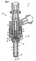
- An injection valve 62 that is in particular suitable for dosing fuel to an internal combustion engine, comprises a valve assembly 60 and an inlet assembly 61.
- the valve assembly 60 comprises a valve body 4 with a central longitudinal axis L and a cavity 8, which takes in a valve needle shaft 10 and preferably a part of an armature 12.
- the valve needle shaft 10 and the armature 12 are forming a valve needle 14.
- the inlet assembly 61 comprises an inlet tube 2.
- an inner cavity 16 is provided in the inlet tube 2 and in the armature 12 .
- a spring 18 is arranged in the inner cavity 16. Preferably, it rests on a spring seat being formed by an anti-bounce disc 20. By this the spring 18 is mechanically coupled to the valve needle 14.
- An adjusting tube 22 is provided in the inner cavity 16. The adjusting tube 22 forms a further seat for the spring 18.
- the valve needle 14 In a closing position of the valve needle 14 it sealingly rests on a seat plate 26.
- the seat plate 26 is arranged in the valve body 4. In the closing position of the valve needle 14 a fluid flow through at least one injection nozzle 24 is prevented.
- the injection nozzle 24 may be, for example, an injection hole. However, it may also be of some other type suitable for dosing fluid.
- a needle guide element 28 is arranged in the cavity 8.
- the needle guide element 28 can guide the valve needle 14 in axial direction.
- the needle guide element 28 has a part 30 which is arranged on a shoulder 33 of the valve body 4.
- the part 30 has a planar shape and is extending in a radial direction.
- the shoulder 33 has a wall section 34 facing away from the fluid outlet portion 44.
- the planar part 30 of the needle guide element 28 is arranged on the wall section 34. Consequently, the planar part 30 is facing away from the fluid outlet portion 44 as well.
- the needle guide element 28 has a further part 32 which is arranged at an inner wall of the cavity 8.
- the further part 32 of the needle guide element 28 is formed as a hollow cylindrical ring element. In a cross sectional view as shown in the figures 2 , 4a and 4b the planar part 30 and the further part 32 of the needle guide element 28 are forming a "L".
- a further needle guide element 35 for guiding the valve needle 14 is provided.
- the further needle guide element 35 is arranged in the cavity 8 near the seat plate 26 or adjacent to the seat plate 26.
- the needle guide element 28 and the further needle guide element 35 enable a secure axial guiding of the valve needle 14 inside the valve body 4.
- the injection valve 62 is provided with an actuator unit that comprises preferably an electromagnetic actuator, comprising a coil 36, which is preferably overmolded.
- an actuator unit may also comprise another type of actuator, which is known to a person skilled in the art for that purpose.
- Such an actuator may be, for example, a piezoelectric actuator.
- a fluid inlet portion 42 is provided in the valve body 4 which communicates with a fluid outlet portion 44 which is a part of the cavity 8 near the seat plate 26.
- the valve body 4 has a recess 46 facing the central longitudinal axis L.
- the planar part 30 of the needle guide element 28 is in engagement with the recess 46 in the valve body 4. By this the needle guide element 28 is fixedly coupled to the valve body 4.
- the fluid is led from the fluid inlet portion 42 to the fluid outlet portion 44.
- the axial position of the valve needle 14, which determines whether the fluid outlet portion 44 is opened or closed for a fluid flow, depends on the force balance between the spring 18 and the forces applied to the valve needle 14 by the actuator unit with the coil 36.
- valve needle 14 In the closing position of the valve needle 14 the valve needle 14 sealingly rests on the seat plate 26 and consequently prevents a fluid flow through the fluid outlet portion 44 and the injection nozzle 24.
- the coil 36 may effect a force on the valve needle 14.
- the valve needle 14 is able to move in axial direction out of the closing position. Outside of the closing position of the valve needle 14, there is a gap between the seat plate 26 and the valve needle 14 at an axial end of the valve needle 14 facing away from the coil 36. This enables a fluid flow through the injection nozzle 24.
- the needle guide element 28 is formed as a ring.
- the planar part 30 of the needle guide element 28 has pressure portions 47 from which tongues 48 are extending in radial direction away from the central longitudinal axis L.
- the needle guide element 28 has three pressure portions 47 and three respective tongues 48.
- the number of the pressure portions 47 and the respective tongues 48 can be smaller than three.
- the number of the pressure portions 47 and the respective tongues 48 is larger than three.
- the tongues 48 of the needle guide elements 28 are extending in radial direction away from the central longitudinal axis L thereby extending into the recesses 46 in the valve body 4. Consequently, the needle guide element 28 is in engagement with the recess 46 in the valve body 4 and the needle guide element 28 is fixedly coupled to the valve body 4.
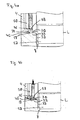
- a tool 50 is shown which is arranged above the shoulder 33 of the valve body 4 and the planar part 30 of the needle guide element 28 during the assembly process.
- the tool 50 can hold down the planar part 30 of the needle guide element 28.
- a further tool 52 is arranged in the cavity 8 of the valve body 4 and can hold the needle guide element 28 in position during the assembly process.
- the tool 50 has at least one aperture 54 which extends in axial direction and has preferably a cylindrical shape.
- a pin element 56 is arranged which can be moved in axial direction.
- the numbers of the apertures 54 and the pin elements 56 are correlated to the number of the tongues 48 which is desired for the secure coupling of the needle guide element 28 with the valve body 4 as will be described in the following.
- the apertures 54 in the tool 50 are arranged on a circle with the centre being arranged on the central longitudinal axis L.
- the angular distance between each of two apertures 54 is equal.
- Each of the pin elements 56 has an end portion 58 which can be brought into engagement with the planar part 30 of the needle guide element 28 as will be described in the following.
- the end portion 58 of the pin element 56 has the shape of a spherical cap.
- the end portion 58 of the pin element 56 has a semispherical shape.
- the valve body 4 will be provided and the recess 46 is formed in the valve body 4 in a manner that the recess 46 faces the central longitudinal axis.
- the recess 46 is formed as a groove which makes it possible that only a minimal effort is necessary for forming the recess 46.
- the needle guide element 28 is provided and arranged in the cavity 8 of the valve body 4 in a manner that the planar part 30 of the needle guide element 28 is arranged on the shoulder 33 of the valve body 4. This means that the planar part 30 is adjacent to the wall section 34 of the shoulder 33 facing away from the fluid outlet portion 44.
- the further part 32 of the needle guide element 28 which is forming a hollow cylinder is arranged on the inner wall of the valve body 4 facing the central longitudinal axis L.
- the pin elements 56 which are arranged in the apertures 54 of the tool 50 are moved in axial direction towards the planar part 30 of the needle guide element 28 until the end portions 58 of the pin elements 56 come into engagement with the planar part 30 of the needle guide element 28 in the area of the pressure portions 47 of the needle guide element 28.
- the planar part 30 is plastically deformed and material from the pressure portions 47 of the planar part 30 of the needle guide element 28 is expanded thereby forming tongues 48 in locally limited areas ( Figure 3 ).
- the tongues 48 come into engagement with the recesses 46 in the valve body 4.
- the described method makes a secure coupling of the needle guide element 28 with the valve body 4 possible.
- the number of pressure portions 47 and tongues 48 is equal or larger than three and the angular distance with respect to the central longitudinal axis L between each of two tongues 48 is approximately equal, a very good mechanical coupling between the needle guide element 28 and the valve body 4 can be obtained.
- the deformation of the needle guide element 28 can be carried out with great care and the production of flaking particles during the assembly process can be prevented.
- valve body 4 can have a large extension in axial direction. This can be seen in particular in Figure 2 where the tool 50 is arranged in a very small area between the valve body 4 and the further tool 52 in radial direction and the valve body 4 extends in both axial directions from the coupling zone between the valve body 4 and the planar part 30 of the needle guide element 28. This means that the tool 50 can be simply inserted into the cavity 8 even in the case that there is only a small space between the valve body 4 and the further tool 52.
Landscapes
- Engineering & Computer Science (AREA)
- Chemical & Material Sciences (AREA)
- Combustion & Propulsion (AREA)
- Mechanical Engineering (AREA)
- General Engineering & Computer Science (AREA)
- Manufacturing & Machinery (AREA)
- Fuel-Injection Apparatus (AREA)
Claims (6)
- Verfahren zum Zusammensetzen einer Ventilanordnung (60) eines Einspritzventils (62),
wobei die Ventilanordnung (60) Folgendes umfasst:- ein Ventilgehäuse (4), das Folgendes aufweist:-- eine zentrale Längsachse (L) und-- einen Hohlraum (8) mit einem Flüssigkeitseinlassabschnitt (42) und einem Flüssigkeitsauslassabschnitt (44),- eine Ventilnadel (14), die im Hohlraum (8) axial beweglich ist, wobei die Ventilnadel (14) in einer Schließposition eine Flüssigkeitsströmung durch den Flüssigkeitsauslassabschnitt (44) verhindert und in weiteren Positionen die Flüssigkeitsströmung durch den Flüssigkeitsauslassabschnitt (44) freigibt, wobei das Verfahren die folgenden Schritte umfasst:- Bereitstellen des Ventilgehäuses (4) und Bilden einer Vertiefung (46) im Ventilgehäuse (4), derart, dass die Vertiefung (46) der zentralen Längsachse (L) zugewandt ist,- Bereitstellen eines Nadelführungselements (28), das ausgestaltet ist, die Ventilnadel (14) im Hohlraum (8) zu führen,- Anordnen und Ausrichten des Nadelführungselements (28) in Bezug zum Ventilgehäuse (4), derart, dass das Nadelführungselement (28) im Hohlraum (8) angeordnet ist und ein Teil (30) des Nadelführungselements (28) auf einem Ansatz (33) des Ventilgehäuses (4) angeordnet ist, der dem Flüssigkeitsauslassabschnitt (44) abgewandt ist,- Verformen des Teils (30) des Nadelführungselements (28) in radialer Richtung, derart, dass der Teil (30) mit der Vertiefung (46) im Ventilgehäuse (4) in Eingriff gelangt und dadurch das Nadelführungselement (28) in Bezug zum Ventilgehäuse (4) fest koppelt. - Verfahren nach Anspruch 1, wobei mindestens ein Stiftelement (56) in axialer Richtung bewegt wird, um den Teil (30) des Nadelführungselements (28) in radialer Richtung zu verformen.
- Verfahren nach Anspruch 2, wobei mehrere Stiftelemente (56) um den Umfang des Ventilgehäuses (4) angeordnet sind und in axialer Richtung bewegt werden, um den Teil (30) des Nadelführungselements (28) zu verformen.
- Verfahren nach Anspruch 2 oder 3, wobei das Stiftelement (56) einen Endabschnitt (58) umfasst, der dem Teil (30) des Nadelführungselements (28) zugewandt ist, wobei der Endabschnitt (58) die Form einer halbgkugelförmigen Kappe aufweist.
- Verfahren nach einem der Ansprüche 2 bis 4, wobei ein Werkzeug (50) in axialer Richtung bewegt wird, um das Nadelführungselement (28) in Bezug zum Ventilgehäuse (4) anzuordnen und auszurichten, wobei das Werkzeug (50) mindestens eine Öffnung (54) umfasst, die sich in axialer Richtung erstreckt, wobei das mindestens eine Stiftelement (56) angeordnet ist, in axialer Richtung bewegt zu werden.
- Ventilanordnung (60) eines Einspritzventils (62),
wobei die Ventilanordnung (60) Folgendes umfasst:- ein Ventilgehäuse (4), das Folgendes aufweist:-- eine zentrale Längsachse (L),-- einen Hohlraum (8) mit einem Flüssigkeitseinlassabschnitt (42) und einem Flüssigkeitsauslassabschnitt (44),-- und eine Vertiefung (46), die der zentralen Längsachse (L) zugewandt ist,- und eine Ventilnadel (14), die im Hohlraum (8) axial beweglich ist, wobei die Ventilnadel (14) in einer Schließposition eine Flüssigkeitsströmung durch den Flüssigkeitsauslassabschnitt (44) verhindert und in weiteren Positionen die Flüssigkeitsströmung durch den Flüssigkeitsauslassabschnitt (44) freigibt, wobei die Ventilanordnung (60) dadurch gekennzeichnet ist, dass sie überdies ein Nadelführungselement (28) umfasst, das konstruiert ist, die Ventilnadel (14) zu führen, und in dem Hohlraum (8) angeordnet ist, wobei- ein Teil (30) des Nadelführungselements (28) auf einem Ansatz (33) des Ventilgehäuses (4) angeordnet ist, der dem Flüssigkeitsauslassabschnitt (44) abgewandt ist, und- der Teil (30) des Nadelführungselements (28) mit der Vertiefung (46) im Ventilgehäuse (4) im Eingriff ist und dadurch das Nadelführungselement (28) in Bezug zum Ventilgehäuse (4) festkoppelt.
Priority Applications (2)
| Application Number | Priority Date | Filing Date | Title |
|---|---|---|---|
| AT09003626T ATE529626T1 (de) | 2009-03-12 | 2009-03-12 | Verfahren zur zusammensetzung der ventilanordnung eines einspritzventils und ventilanordnung eines einspritzventils |
| EP09003626A EP2228532B1 (de) | 2009-03-12 | 2009-03-12 | Verfahren zur Zusammensetzung der Ventilanordnung eines Einspritzventils und Ventilanordnung eines Einspritzventils |
Applications Claiming Priority (1)
| Application Number | Priority Date | Filing Date | Title |
|---|---|---|---|
| EP09003626A EP2228532B1 (de) | 2009-03-12 | 2009-03-12 | Verfahren zur Zusammensetzung der Ventilanordnung eines Einspritzventils und Ventilanordnung eines Einspritzventils |
Publications (2)
| Publication Number | Publication Date |
|---|---|
| EP2228532A1 EP2228532A1 (de) | 2010-09-15 |
| EP2228532B1 true EP2228532B1 (de) | 2011-10-19 |
Family
ID=40984798
Family Applications (1)
| Application Number | Title | Priority Date | Filing Date |
|---|---|---|---|
| EP09003626A Not-in-force EP2228532B1 (de) | 2009-03-12 | 2009-03-12 | Verfahren zur Zusammensetzung der Ventilanordnung eines Einspritzventils und Ventilanordnung eines Einspritzventils |
Country Status (2)
| Country | Link |
|---|---|
| EP (1) | EP2228532B1 (de) |
| AT (1) | ATE529626T1 (de) |
Family Cites Families (5)
| Publication number | Priority date | Publication date | Assignee | Title |
|---|---|---|---|---|
| JP2003232268A (ja) * | 2002-02-08 | 2003-08-22 | Hitachi Ltd | 電磁式燃料噴射弁 |
| JP2005248846A (ja) * | 2004-03-04 | 2005-09-15 | Bosch Automotive Systems Corp | 燃料通路のシール構造及びそのシール構造を備えた燃料噴射弁 |
| DE102005037951A1 (de) * | 2005-08-11 | 2007-02-15 | Robert Bosch Gmbh | Verfahren zur Herstellung eines festen Gehäuses |
| DE102007008863A1 (de) * | 2005-08-26 | 2008-08-28 | Robert Bosch Gmbh | Brennstoffeinspritzventil |
| DE102005061408A1 (de) * | 2005-12-22 | 2007-06-28 | Robert Bosch Gmbh | Kunststoff-Metall-Verbindung und Brennstoffeinspritzventil mit einer Kraftstoff-Metall-Verbindung |
-
2009
- 2009-03-12 EP EP09003626A patent/EP2228532B1/de not_active Not-in-force
- 2009-03-12 AT AT09003626T patent/ATE529626T1/de not_active IP Right Cessation
Also Published As
| Publication number | Publication date |
|---|---|
| ATE529626T1 (de) | 2011-11-15 |
| EP2228532A1 (de) | 2010-09-15 |
Similar Documents
| Publication | Publication Date | Title |
|---|---|---|
| EP2333297B1 (de) | Ventilanordnung für ein Einspritzventil und Einspritzventil | |
| CN1064742C (zh) | 用于电磁操作阀的阀针及制造方法 | |
| EP2000662B1 (de) | Einstellungs- und Filteranordnung für ein Einspritzventil und Einspritzventil | |
| EP2535552B1 (de) | Ventilanordnung für ein Einspritzventil und Einspritzventil | |
| EP2706220B1 (de) | Ventilanordnung für ein Einspritzventil und Einspritzventil | |
| EP2366888A1 (de) | Ventilgruppe für ein Einspritzventil, Einspritzventil und Verfahren zum Zusammenbauen einer Ventilgruppe eines Einspritzventils | |
| EP2354528B1 (de) | Ventilanordnung und Einspritzventil | |
| EP2375051A1 (de) | Ventilanordnung für ein Einspritzventil und Einspritzventil | |
| KR20020027487A (ko) | 분사 밸브의 밸브 행정 조정 방법 | |
| EP2228532A1 (de) | Verfahren zur Zusammensetzung der Ventilanordnung eines Einspritzventils und Ventilanordnung eines Einspritzventils | |
| US7607636B2 (en) | Valve assembly for an injection valve and injection valve | |
| EP2378106A1 (de) | Ventilanordnung für ein Einspritzventil und Einspritzventil | |
| EP2282042B1 (de) | Ventilanordnung und Einspritzventil | |
| US7370816B2 (en) | Fuel injector | |
| EP2003331A1 (de) | Ventilanordnung für ein Einspritzventil und Einspritzventil | |
| EP2466109A1 (de) | Ventilanordnung für ein Einspritzventil und Einspritzventil | |
| EP2385239A1 (de) | Ventilanordnung für ein Einspritzventil und Einspritzventil | |
| EP1865194B1 (de) | Verfahren zur Einstellung eines Brennstoffeinspritzventils | |
| EP1816344A1 (de) | Düsenanordnung für eine Einspritzdüse und Einspritzdüse | |
| EP2216542A1 (de) | Ventilanordnung für ein Einspritzventil und Einspritzventil | |
| EP2363595A1 (de) | Ventilanordnung für ein Einspritzventil und Einspritzventil | |
| EP2241743B1 (de) | Ventilanordnung für ein Einspritzventil und Einspritzventil | |
| EP1865191A1 (de) | Anordnung zur Einstellung eines Einspritzventils, Einspritzventil und Verfahren zur Einstellung eines Einspritzventils | |
| EP2698525A1 (de) | Ventilnadel, Ventilanordnung und Einspritzdüse | |
| EP2439400A1 (de) | Ventilanordnung für ein Einspritzventil und Einspritzventil |
Legal Events
| Date | Code | Title | Description |
|---|---|---|---|
| PUAI | Public reference made under article 153(3) epc to a published international application that has entered the european phase |
Free format text: ORIGINAL CODE: 0009012 |
|
| AK | Designated contracting states |
Kind code of ref document: A1 Designated state(s): AT BE BG CH CY CZ DE DK EE ES FI FR GB GR HR HU IE IS IT LI LT LU LV MC MK MT NL NO PL PT RO SE SI SK TR |
|
| AX | Request for extension of the european patent |
Extension state: AL BA RS |
|
| 17P | Request for examination filed |
Effective date: 20110315 |
|
| GRAP | Despatch of communication of intention to grant a patent |
Free format text: ORIGINAL CODE: EPIDOSNIGR1 |
|
| AKX | Designation fees paid |
Designated state(s): AT BE BG CH CY CZ DE DK EE ES FI FR GB GR HR HU IE IS IT LI LT LU LV MC MK MT NL NO PL PT RO SE SI SK TR |
|
| GRAS | Grant fee paid |
Free format text: ORIGINAL CODE: EPIDOSNIGR3 |
|
| GRAA | (expected) grant |
Free format text: ORIGINAL CODE: 0009210 |
|
| AK | Designated contracting states |
Kind code of ref document: B1 Designated state(s): AT BE BG CH CY CZ DE DK EE ES FI FR GB GR HR HU IE IS IT LI LT LU LV MC MK MT NL NO PL PT RO SE SI SK TR |
|
| REG | Reference to a national code |
Ref country code: GB Ref legal event code: FG4D |
|
| REG | Reference to a national code |
Ref country code: CH Ref legal event code: EP |
|
| REG | Reference to a national code |
Ref country code: IE Ref legal event code: FG4D |
|
| REG | Reference to a national code |
Ref country code: DE Ref legal event code: R096 Ref document number: 602009003119 Country of ref document: DE Effective date: 20111208 |
|
| REG | Reference to a national code |
Ref country code: NL Ref legal event code: VDEP Effective date: 20111019 |
|
| LTIE | Lt: invalidation of european patent or patent extension |
Effective date: 20111019 |
|
| REG | Reference to a national code |
Ref country code: AT Ref legal event code: MK05 Ref document number: 529626 Country of ref document: AT Kind code of ref document: T Effective date: 20111019 |
|
| PG25 | Lapsed in a contracting state [announced via postgrant information from national office to epo] |
Ref country code: IS Free format text: LAPSE BECAUSE OF FAILURE TO SUBMIT A TRANSLATION OF THE DESCRIPTION OR TO PAY THE FEE WITHIN THE PRESCRIBED TIME-LIMIT Effective date: 20120219 Ref country code: NO Free format text: LAPSE BECAUSE OF FAILURE TO SUBMIT A TRANSLATION OF THE DESCRIPTION OR TO PAY THE FEE WITHIN THE PRESCRIBED TIME-LIMIT Effective date: 20120119 Ref country code: LT Free format text: LAPSE BECAUSE OF FAILURE TO SUBMIT A TRANSLATION OF THE DESCRIPTION OR TO PAY THE FEE WITHIN THE PRESCRIBED TIME-LIMIT Effective date: 20111019 Ref country code: BE Free format text: LAPSE BECAUSE OF FAILURE TO SUBMIT A TRANSLATION OF THE DESCRIPTION OR TO PAY THE FEE WITHIN THE PRESCRIBED TIME-LIMIT Effective date: 20111019 |
|
| PG25 | Lapsed in a contracting state [announced via postgrant information from national office to epo] |
Ref country code: LV Free format text: LAPSE BECAUSE OF FAILURE TO SUBMIT A TRANSLATION OF THE DESCRIPTION OR TO PAY THE FEE WITHIN THE PRESCRIBED TIME-LIMIT Effective date: 20111019 Ref country code: HR Free format text: LAPSE BECAUSE OF FAILURE TO SUBMIT A TRANSLATION OF THE DESCRIPTION OR TO PAY THE FEE WITHIN THE PRESCRIBED TIME-LIMIT Effective date: 20111019 Ref country code: GR Free format text: LAPSE BECAUSE OF FAILURE TO SUBMIT A TRANSLATION OF THE DESCRIPTION OR TO PAY THE FEE WITHIN THE PRESCRIBED TIME-LIMIT Effective date: 20120120 Ref country code: PT Free format text: LAPSE BECAUSE OF FAILURE TO SUBMIT A TRANSLATION OF THE DESCRIPTION OR TO PAY THE FEE WITHIN THE PRESCRIBED TIME-LIMIT Effective date: 20120220 Ref country code: NL Free format text: LAPSE BECAUSE OF FAILURE TO SUBMIT A TRANSLATION OF THE DESCRIPTION OR TO PAY THE FEE WITHIN THE PRESCRIBED TIME-LIMIT Effective date: 20111019 Ref country code: SI Free format text: LAPSE BECAUSE OF FAILURE TO SUBMIT A TRANSLATION OF THE DESCRIPTION OR TO PAY THE FEE WITHIN THE PRESCRIBED TIME-LIMIT Effective date: 20111019 Ref country code: SE Free format text: LAPSE BECAUSE OF FAILURE TO SUBMIT A TRANSLATION OF THE DESCRIPTION OR TO PAY THE FEE WITHIN THE PRESCRIBED TIME-LIMIT Effective date: 20111019 |
|
| PG25 | Lapsed in a contracting state [announced via postgrant information from national office to epo] |
Ref country code: CY Free format text: LAPSE BECAUSE OF FAILURE TO SUBMIT A TRANSLATION OF THE DESCRIPTION OR TO PAY THE FEE WITHIN THE PRESCRIBED TIME-LIMIT Effective date: 20111019 |
|
| PG25 | Lapsed in a contracting state [announced via postgrant information from national office to epo] |
Ref country code: CZ Free format text: LAPSE BECAUSE OF FAILURE TO SUBMIT A TRANSLATION OF THE DESCRIPTION OR TO PAY THE FEE WITHIN THE PRESCRIBED TIME-LIMIT Effective date: 20111019 Ref country code: DK Free format text: LAPSE BECAUSE OF FAILURE TO SUBMIT A TRANSLATION OF THE DESCRIPTION OR TO PAY THE FEE WITHIN THE PRESCRIBED TIME-LIMIT Effective date: 20111019 Ref country code: SK Free format text: LAPSE BECAUSE OF FAILURE TO SUBMIT A TRANSLATION OF THE DESCRIPTION OR TO PAY THE FEE WITHIN THE PRESCRIBED TIME-LIMIT Effective date: 20111019 Ref country code: BG Free format text: LAPSE BECAUSE OF FAILURE TO SUBMIT A TRANSLATION OF THE DESCRIPTION OR TO PAY THE FEE WITHIN THE PRESCRIBED TIME-LIMIT Effective date: 20120119 Ref country code: EE Free format text: LAPSE BECAUSE OF FAILURE TO SUBMIT A TRANSLATION OF THE DESCRIPTION OR TO PAY THE FEE WITHIN THE PRESCRIBED TIME-LIMIT Effective date: 20111019 |
|
| PLBE | No opposition filed within time limit |
Free format text: ORIGINAL CODE: 0009261 |
|
| STAA | Information on the status of an ep patent application or granted ep patent |
Free format text: STATUS: NO OPPOSITION FILED WITHIN TIME LIMIT |
|
| PG25 | Lapsed in a contracting state [announced via postgrant information from national office to epo] |
Ref country code: RO Free format text: LAPSE BECAUSE OF FAILURE TO SUBMIT A TRANSLATION OF THE DESCRIPTION OR TO PAY THE FEE WITHIN THE PRESCRIBED TIME-LIMIT Effective date: 20111019 Ref country code: PL Free format text: LAPSE BECAUSE OF FAILURE TO SUBMIT A TRANSLATION OF THE DESCRIPTION OR TO PAY THE FEE WITHIN THE PRESCRIBED TIME-LIMIT Effective date: 20111019 |
|
| 26N | No opposition filed |
Effective date: 20120720 |
|
| PG25 | Lapsed in a contracting state [announced via postgrant information from national office to epo] |
Ref country code: MC Free format text: LAPSE BECAUSE OF NON-PAYMENT OF DUE FEES Effective date: 20120331 |
|
| REG | Reference to a national code |
Ref country code: DE Ref legal event code: R097 Ref document number: 602009003119 Country of ref document: DE Effective date: 20120720 |
|
| REG | Reference to a national code |
Ref country code: IE Ref legal event code: MM4A |
|
| PG25 | Lapsed in a contracting state [announced via postgrant information from national office to epo] |
Ref country code: AT Free format text: LAPSE BECAUSE OF FAILURE TO SUBMIT A TRANSLATION OF THE DESCRIPTION OR TO PAY THE FEE WITHIN THE PRESCRIBED TIME-LIMIT Effective date: 20111019 Ref country code: IE Free format text: LAPSE BECAUSE OF NON-PAYMENT OF DUE FEES Effective date: 20120312 |
|
| PG25 | Lapsed in a contracting state [announced via postgrant information from national office to epo] |
Ref country code: MK Free format text: LAPSE BECAUSE OF FAILURE TO SUBMIT A TRANSLATION OF THE DESCRIPTION OR TO PAY THE FEE WITHIN THE PRESCRIBED TIME-LIMIT Effective date: 20111019 |
|
| PG25 | Lapsed in a contracting state [announced via postgrant information from national office to epo] |
Ref country code: ES Free format text: LAPSE BECAUSE OF FAILURE TO SUBMIT A TRANSLATION OF THE DESCRIPTION OR TO PAY THE FEE WITHIN THE PRESCRIBED TIME-LIMIT Effective date: 20120130 |
|
| PG25 | Lapsed in a contracting state [announced via postgrant information from national office to epo] |
Ref country code: FI Free format text: LAPSE BECAUSE OF FAILURE TO SUBMIT A TRANSLATION OF THE DESCRIPTION OR TO PAY THE FEE WITHIN THE PRESCRIBED TIME-LIMIT Effective date: 20111019 |
|
| PG25 | Lapsed in a contracting state [announced via postgrant information from national office to epo] |
Ref country code: MT Free format text: LAPSE BECAUSE OF FAILURE TO SUBMIT A TRANSLATION OF THE DESCRIPTION OR TO PAY THE FEE WITHIN THE PRESCRIBED TIME-LIMIT Effective date: 20111019 |
|
| REG | Reference to a national code |
Ref country code: CH Ref legal event code: PL |
|
| GBPC | Gb: european patent ceased through non-payment of renewal fee |
Effective date: 20130312 |
|
| PG25 | Lapsed in a contracting state [announced via postgrant information from national office to epo] |
Ref country code: LI Free format text: LAPSE BECAUSE OF NON-PAYMENT OF DUE FEES Effective date: 20130331 Ref country code: GB Free format text: LAPSE BECAUSE OF NON-PAYMENT OF DUE FEES Effective date: 20130312 Ref country code: CH Free format text: LAPSE BECAUSE OF NON-PAYMENT OF DUE FEES Effective date: 20130331 |
|
| PG25 | Lapsed in a contracting state [announced via postgrant information from national office to epo] |
Ref country code: TR Free format text: LAPSE BECAUSE OF FAILURE TO SUBMIT A TRANSLATION OF THE DESCRIPTION OR TO PAY THE FEE WITHIN THE PRESCRIBED TIME-LIMIT Effective date: 20111019 |
|
| PG25 | Lapsed in a contracting state [announced via postgrant information from national office to epo] |
Ref country code: LU Free format text: LAPSE BECAUSE OF NON-PAYMENT OF DUE FEES Effective date: 20120312 |
|
| PG25 | Lapsed in a contracting state [announced via postgrant information from national office to epo] |
Ref country code: HU Free format text: LAPSE BECAUSE OF FAILURE TO SUBMIT A TRANSLATION OF THE DESCRIPTION OR TO PAY THE FEE WITHIN THE PRESCRIBED TIME-LIMIT Effective date: 20090312 |
|
| REG | Reference to a national code |
Ref country code: FR Ref legal event code: PLFP Year of fee payment: 8 |
|
| REG | Reference to a national code |
Ref country code: FR Ref legal event code: PLFP Year of fee payment: 9 |
|
| REG | Reference to a national code |
Ref country code: FR Ref legal event code: PLFP Year of fee payment: 10 |
|
| PGFP | Annual fee paid to national office [announced via postgrant information from national office to epo] |
Ref country code: FR Payment date: 20180328 Year of fee payment: 10 |
|
| PGFP | Annual fee paid to national office [announced via postgrant information from national office to epo] |
Ref country code: DE Payment date: 20180331 Year of fee payment: 10 |
|
| PGFP | Annual fee paid to national office [announced via postgrant information from national office to epo] |
Ref country code: IT Payment date: 20180327 Year of fee payment: 10 |
|
| REG | Reference to a national code |
Ref country code: DE Ref legal event code: R119 Ref document number: 602009003119 Country of ref document: DE |
|
| PG25 | Lapsed in a contracting state [announced via postgrant information from national office to epo] |
Ref country code: DE Free format text: LAPSE BECAUSE OF NON-PAYMENT OF DUE FEES Effective date: 20191001 |
|
| PG25 | Lapsed in a contracting state [announced via postgrant information from national office to epo] |
Ref country code: IT Free format text: LAPSE BECAUSE OF NON-PAYMENT OF DUE FEES Effective date: 20190312 Ref country code: FR Free format text: LAPSE BECAUSE OF NON-PAYMENT OF DUE FEES Effective date: 20190331 |