EP2535552B1 - Ventilanordnung für ein Einspritzventil und Einspritzventil - Google Patents
Ventilanordnung für ein Einspritzventil und Einspritzventil Download PDFInfo
- Publication number
- EP2535552B1 EP2535552B1 EP11169988.0A EP11169988A EP2535552B1 EP 2535552 B1 EP2535552 B1 EP 2535552B1 EP 11169988 A EP11169988 A EP 11169988A EP 2535552 B1 EP2535552 B1 EP 2535552B1
- Authority
- EP
- European Patent Office
- Prior art keywords
- armature
- valve
- valve needle
- cavity
- retainer
- Prior art date
- Legal status (The legal status is an assumption and is not a legal conclusion. Google has not performed a legal analysis and makes no representation as to the accuracy of the status listed.)
- Not-in-force
Links
Images
Classifications
-
- F—MECHANICAL ENGINEERING; LIGHTING; HEATING; WEAPONS; BLASTING
- F02—COMBUSTION ENGINES; HOT-GAS OR COMBUSTION-PRODUCT ENGINE PLANTS
- F02M—SUPPLYING COMBUSTION ENGINES IN GENERAL WITH COMBUSTIBLE MIXTURES OR CONSTITUENTS THEREOF
- F02M51/00—Fuel-injection apparatus characterised by being operated electrically
- F02M51/06—Injectors peculiar thereto with means directly operating the valve needle
- F02M51/061—Injectors peculiar thereto with means directly operating the valve needle using electromagnetic operating means
- F02M51/0625—Injectors peculiar thereto with means directly operating the valve needle using electromagnetic operating means characterised by arrangement of mobile armatures
- F02M51/0635—Injectors peculiar thereto with means directly operating the valve needle using electromagnetic operating means characterised by arrangement of mobile armatures having a plate-shaped or undulated armature not entering the winding
- F02M51/066—Injectors peculiar thereto with means directly operating the valve needle using electromagnetic operating means characterised by arrangement of mobile armatures having a plate-shaped or undulated armature not entering the winding the armature and the valve being allowed to move relatively to each other or not being attached to each other
-
- F—MECHANICAL ENGINEERING; LIGHTING; HEATING; WEAPONS; BLASTING
- F02—COMBUSTION ENGINES; HOT-GAS OR COMBUSTION-PRODUCT ENGINE PLANTS
- F02M—SUPPLYING COMBUSTION ENGINES IN GENERAL WITH COMBUSTIBLE MIXTURES OR CONSTITUENTS THEREOF
- F02M51/00—Fuel-injection apparatus characterised by being operated electrically
- F02M51/06—Injectors peculiar thereto with means directly operating the valve needle
- F02M51/061—Injectors peculiar thereto with means directly operating the valve needle using electromagnetic operating means
- F02M51/0625—Injectors peculiar thereto with means directly operating the valve needle using electromagnetic operating means characterised by arrangement of mobile armatures
- F02M51/0664—Injectors peculiar thereto with means directly operating the valve needle using electromagnetic operating means characterised by arrangement of mobile armatures having a cylindrically or partly cylindrically shaped armature, e.g. entering the winding; having a plate-shaped or undulated armature entering the winding
-
- F—MECHANICAL ENGINEERING; LIGHTING; HEATING; WEAPONS; BLASTING
- F02—COMBUSTION ENGINES; HOT-GAS OR COMBUSTION-PRODUCT ENGINE PLANTS
- F02M—SUPPLYING COMBUSTION ENGINES IN GENERAL WITH COMBUSTIBLE MIXTURES OR CONSTITUENTS THEREOF
- F02M2200/00—Details of fuel-injection apparatus, not otherwise provided for
- F02M2200/30—Fuel-injection apparatus having mechanical parts, the movement of which is damped
- F02M2200/306—Fuel-injection apparatus having mechanical parts, the movement of which is damped using mechanical means
Definitions
- the invention relates to a valve assembly for an injection valve and an injection valve.
- Injection valves are in wide spread use, in particular for internal combustion engines where they may be arranged in order to dose the fluid into an intake manifold of the internal combustion engine or directly into the combustion chamber of a cylinder of the internal combustion engine.
- injection valves are manufactured in various forms in order to satisfy the various needs for the various combustion engines. Therefore, for example, their length, their diameter and also various elements of the injection valve being responsible for the way the fluid is dosed may vary in a wide range.
- injection valves may accommodate an actuator for actuating a needle of the injection valve, which may, for example, be an electromagnetic actuator or piezo electric actuator.
- the respective injection valve may be suited to dose fluids under very high pressures.
- the injection valve may be suited to dose very small quantities of fluid under very high pressures. These pressures may be in case of a gasoline engine, for example, in the range of up to 200 bar and in the case of diesel engines in the range of more than 2000 bar.
- EP 1 460 263 Al discloses an injection valve comprising a housing, a fuel chamber with an inlet to the fuel chamber, an orifice with a valve seat, a holding element that is movably arranged within the housing, whereby the holding element is connected with a needle, and an actuator that controls the position of the holding element.
- EP 2 527 637 A1 which is state of the art according to Art. 54(3) EPC, discloses an injector for injecting fluid which comprises a valve needle, an armature, a needle retainer and an armature holder.
- the needle retainer is fixed to the valve needle and the armature holder is fixed to the armature.
- the needle retainer and the armature holder are releasably coupleable such that when the armature moves in the first direction, the needle is moved in the first direction by the movement of the armature holder and the needle retainer.
- the object of the invention is to create a valve assembly which facilitates a reliable and precise function.
- the invention is distinguished by a valve assembly for an injection valve, comprising a valve body including a central longitudinal axis, the valve body comprising a cavity with a fluid inlet portion and a fluid outlet portion, a valve needle axially movable in the cavity, the valve needle preventing a fluid flow through the fluid outlet portion in a closing position and releasing the fluid flow through the fluid outlet portion in further positions, the valve needle comprising a protrusion extending in radial direction, and an electro-magnetic actuator unit being designed to actuate the valve needle.
- the electro-magnetic actuator unit comprises an armature axially movable in the cavity.
- the armature comprises an armature cavity.
- the armature cavity has a first stop surface and a second stop surface.
- the normals of the stop surfaces are essentially orientated in axial direction.
- the second stop surface essentially faces the first stop surface.
- the protrusion of the valve needle is arranged in the armature cavity axially between the first stop surface and the second stop surface in such a manner that a relative movement between the valve needle and the armature in axial direction is limited in that the valve needle may float between the two stop surfaces of the armature in the range of a blind lift to perform the opening and closing movement.
- the armature comprises an armature main body and an armature retainer.
- the armature retainer is fixedly coupled to the armature main body and is shaped in a manner that the armature retainer and the armature main body form the armature cavity. This has the advantage that the armature with the armature cavity may be easily manufactured.
- the armature retainer is shaped as an annular collar. This has the advantage that the armature retainer may be easily manufactured. Furthermore, the armature cavity with the stop surfaces may have a well-defined shape.
- the longitudinal cross section of the armature retainer has an L-shape. This has the advantage that the armature retainer may be easily manufactured.
- a spring element is arranged in the armature cavity axially between the protrusion of the valve needle and the armature retainer.
- the spring element is a coil spring or a wave spring. This has the advantage that a simple shape of the spring element and a low cost solution is possible. Furthermore, a secure arrangement of the spring element in the armature cavity may be obtained.
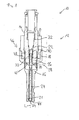
- An injection valve 10 that is in particular suitable for dosing fuel to an internal combustion engine comprises in particular a valve assembly 12 and an inlet tube 14.
- the valve assembly 12 comprises a valve body 16 with a central longitudinal axis L.
- the valve assembly 12 has a housing 18 which is partially arranged around the valve body 16.
- a cavity 20 is arranged in the valve body 16.
- the cavity 20 comprises a fluid outlet portion 21 and a fluid inlet portion 22.
- the fluid outlet portion 21 is in hydraulic communication with the fluid inlet portion 22.
- the cavity 20 takes in a valve needle 24 and an armature 26.
- the valve needle 24 is axially movable in the cavity 20.
- the valve needle 24 comprises a protrusion 28.
- the protrusion 28 is formed as a collar around the valve needle 24.
- the protrusion 28 is fixedly coupled to the valve needle 24.
- the armature 26 is axially movable in the cavity 20.
- a main spring 30 is arranged in a recess 32 which is provided in the inlet tube 14.
- the main spring 30 is mechanically coupled to a guide element 33.
- the guide element 33 is fixedly coupled to the valve needle 24.
- the main spring 30 exerts a force on the guide element 33 and, consequently, on the valve needle 24 towards an injection nozzle 34 of the injection valve 10.
- the injection nozzle 34 may be, for example, an injection hole.
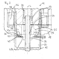
- the armature 26 has an armature cavity 36.
- the armature 26 has an armature main body 38 and an armature retainer 40.
- the armature retainer 40 is fixedly coupled to the armature main body 38.
- the armature main body 38 and the armature retainer 40 form the armature cavity 36.
- the armature retainer 40 is shaped as a collar with an L-shaped longitudinal cross section.
- the armature cavity 36 has a first stop surface 42a and a second stop surface 42b.
- the normal of the first stop surface 42a and the normal of the second stop surface 42b are orientated in axial direction.
- the second stop surface 42b faces the first stop surface 42a.
- the protrusion 28 of the valve needle 24 is arranged in the armature cavity 36 axially between the first stop surface 42a and the second stop surface 42b. By this a relative movement between the valve needle 24 and the armature 26 in axial direction is limited.
- valve needle 24 In a closing position of the valve needle 24 it sealingly rests on a seat plate 44 by this preventing a fluid flow through the at least one injection nozzle 34.
- the valve assembly 12 is provided with an actuator unit 46 that is preferably an electro-magnetic actuator.
- the electro-magnetic actuator unit 46 comprises a coil 48, which is preferably arranged inside the housing 18. Furthermore, the electro-magnetic actuator unit 46 comprises the armature main body 38.
- the valve body 16, the housing 18, the inlet tube 14 and the armature main body 38 are forming an electromagnetic circuit.
- a spring element 50 is arranged in the armature cavity 36 axially between the protrusion 28 of the valve needle 24 and the armature retainer 40 of the armature 26.
- the spring element 50 causes an axial basic distance (blind lift B, Figure 2 ) between the protrusion 28 and the armature retainer 40 during a static condition of the valve assembly 12.
- the spring element 50 enables a dampened transmission of movements between the armature retainer 40 of the armature 26 and the protrusion 28 of the valve needle 24.
- the fluid is led through the recess 32 of the fluid inlet tube 14 to the fluid inlet portion 22 in the valve body 16. Subsequently, the fluid is led towards the fluid outlet portion 21 in the valve body 16.
- the valve needle 24 prevents a fluid flow through the fluid outlet portion 21 in the valve body 16 in a closing position of the valve needle 24. Outside of the closing position of the valve needle 24, the valve needle 24 enables the fluid flow through the fluid outlet portion 21.
- the actuator unit 46 may affect an electro-magnetic force on the armature 26.
- the armature 26 is attracted by the electro-magnetic actuator unit 46 with the coil 48 and moves in axial direction away from the fluid outlet portion 21.
- the armature 26 takes the valve needle 24 with it. Consequently, the valve needle 24 moves in axial direction out of the closing position.
- the gap between the valve body 16 and the valve needle 24 at the axial end of the injection valve 10 facing away from of the actuator unit 46 forms a fluid path and fluid can pass through the injection nozzle 34.
- the main spring 30 can force the valve needle 24 to move in axial direction in its closing position. It is depending on the force balance between the force on the valve needle 24 caused by the actuator unit 46 with the coil 48 and the force on the valve needle 24 caused by the main spring 30 whether the valve needle 24 is in its closing position or not.
- the arrangement of the protrusion 28 of the valve needle 24 in the armature cavity 36 between the two stop surfaces 42a, 42b enables a limited range of relative positions between the armature 26 and the protrusion 28 of the valve needle 24.
- the valve needle 24 may float between the two stop surfaces 42a, 42b of the armature 26 in the range of the blind lift B to perform the opening and closing movement.
- the wearing between the protrusion 28 of the valve needle 24 and the armature 26 can be kept small. Consequently, a stable performance of the operation of the injection valve 10 can be obtained over a long term operating period of the injection valve 10. Furthermore, as the contact surface between the protrusion 28 of the valve needle 24 and the armature 26 may be so large that the contact pressure between the protrusion 28 of the valve needle 24 and the armature 26 can be kept small, a protective coating in the contact area between the armature retainer 40 and the protrusion 28 of the valve needle 24 may be avoided.
- the protrusion 28 may be separate from the valve needle 24 and the armature retainer 40 may be separate from the armature 26
- the protrusion 28 of the valve needle 24 and the armature retainer 40 need not be part of the magnetic circuit. Therefore, a simple hardening process can be carried out for the surfaces of the protrusion 28 of the valve needle 24 and the armature retainer 40 to keep the wearing of these two components small.
- an overshoot of the valve needle 24 and the armature 26 during the opening and the closing of the injection valve 10 can be kept small so that a very good dynamic control of the injection valve 10 can be obtained.
- the guide element 33 is performing a guide function only without any additional task to perform the movement of the valve needle 24 during the opening or closing process.
- the armature 26 is decoupled from the valve needle 24 in a manner that the protrusion 28 allows the relative movement of the armature 26 relative to the valve needle 24.
- the protrusion 28 may limit the overshoot of the armature 26 as well as the overshoot of the valve needle 24.
- the dynamic behavior of the valve needle 24 is dampened. Therefore, the wearing effects on the armature 26 and/or the valve needle 24 in the contact area between the valve needle 24 and/or the armature 26 may be kept small during the opening or closing of the valve needle 24. Consequently, a good long term contact between the valve needle 24 and the armature 26 may be obtained.
Landscapes
- Engineering & Computer Science (AREA)
- Physics & Mathematics (AREA)
- Electromagnetism (AREA)
- Chemical & Material Sciences (AREA)
- Combustion & Propulsion (AREA)
- Mechanical Engineering (AREA)
- General Engineering & Computer Science (AREA)
- Fuel-Injection Apparatus (AREA)
- Magnetically Actuated Valves (AREA)
Claims (5)
- Ventilanordnung (12) für ein Einspritzventil (10), umfassend- einen Ventilkörper (16), umfassend eine zentrale Längsachse (L), wobei der Ventilkörper (16) einen Hohlraum (20) mit einem Fluid-Einlassabschnitt (22) und einem Fluid-Auslassabschnitt (21) umfasst,- eine Ventilnadel (24), die in dem Hohlraum (20) axial beweglich ist, wobei die Ventilnadel (24) ein Fließen des Fluids durch den Fluid-Auslassabschnitt (21) in einer Schließposition verhindert und das Fließen des Fluids durch den Fluid-Auslassabschnitt in weiteren Positionen ermöglicht, wobei die Ventilnadel (24) einen Vorsprung (28) umfasst, der sich in radialer Richtung erstreckt,- einen elektromagnetischen Stellantrieb (46), der eingerichtet ist, die Ventilnadel (24) zu betätigen, wobei der elektromagnetische Stellantrieb (46) einen Anker (26) umfasst, der in dem Hohlraum (20) axial beweglich ist,wobei der Anker (26) einen Ankerhohlraum (36) umfasst, wobei der Ankerhohlraum (36) eine erste Anschlagfläche (42a) und eine zweite Anschlagfläche (42b) aufweist, wobei die Normalen der Anschlagflächen (42a, 42b) im Wesentlichen in einer axialen Richtung ausgerichtet sind, wobei die zweite Anschlagfläche (42b) im Wesentlichen der ersten Anschlagfläche (42a) gegenüberliegt, und wobei der Vorsprung (28) der Ventilnadel (24) in dem Ankerhohlraum (36) axial zwischen der ersten Anschlagfläche (42a) und der zweiten Anschlagfläche (42b) derart eingerichtet ist, dass eine relative Bewegung zwischen der Ventilnadel (24) und dem Anker (26) in axialer Richtung so begrenzt ist, dass die Ventilnadel (24) zwischen den zwei Anschlagflächen (42a, 42b) des Ankers (26) in dem Bereich eines Blindhubs (B) schwimmen kann, um die Öffnungsund Schließbewegung durchzuführen,
wobei der Anker (26) einen Ankerhauptkörper (38) und eine Ankerhalterung (40) umfasst, wobei die Ankerhalterung (40) fest an den Ankerhauptkörper (38) gekoppelt ist und derart geformt ist, dass die Ankerhalterung (40) und der Ankerhauptkörper (38) den Ankerhohlraum (36) bilden, dadurch gekennzeichnet, dass ein Federelement (50) in dem Ankerhohlraum (36) axial zwischen dem Vorsprung (28) der Ventilnadel (24) und der Ankerhalterung (40) angeordnet ist. - Ventilanordnung (12) nach Anspruch 1, wobei die Ankerhalterung (40) wie eine ringförmige Manschette geformt ist.
- Ventilanordnung (12) nach Anspruch 1 oder 2, wobei der Längsquerschnitt der Ankerhalterung (40) L-förmig ist.
- Ventilanordnung (12) nach einem der vorhergehenden Ansprüche, wobei das Federelement (50) eine Schraubenfeder oder eine Wellenfeder ist.
- Einspritzventil (10) mit einer Ventilanordnung (12) nach einem der vorhergehenden Ansprüche.
Priority Applications (4)
| Application Number | Priority Date | Filing Date | Title |
|---|---|---|---|
| EP11169988.0A EP2535552B1 (de) | 2011-06-15 | 2011-06-15 | Ventilanordnung für ein Einspritzventil und Einspritzventil |
| KR1020120064552A KR101964793B1 (ko) | 2011-06-15 | 2012-06-15 | 분사 밸브 및 분사 밸브용 밸브 조립체 |
| CN201210268966.4A CN102828873B (zh) | 2011-06-15 | 2012-06-15 | 喷射阀的阀组件和喷射阀 |
| US13/524,151 US8931718B2 (en) | 2011-06-15 | 2012-06-15 | Valve assembly for an injection valve and injection valve |
Applications Claiming Priority (1)
| Application Number | Priority Date | Filing Date | Title |
|---|---|---|---|
| EP11169988.0A EP2535552B1 (de) | 2011-06-15 | 2011-06-15 | Ventilanordnung für ein Einspritzventil und Einspritzventil |
Publications (2)
| Publication Number | Publication Date |
|---|---|
| EP2535552A1 EP2535552A1 (de) | 2012-12-19 |
| EP2535552B1 true EP2535552B1 (de) | 2015-02-25 |
Family
ID=44773458
Family Applications (1)
| Application Number | Title | Priority Date | Filing Date |
|---|---|---|---|
| EP11169988.0A Not-in-force EP2535552B1 (de) | 2011-06-15 | 2011-06-15 | Ventilanordnung für ein Einspritzventil und Einspritzventil |
Country Status (4)
| Country | Link |
|---|---|
| US (1) | US8931718B2 (de) |
| EP (1) | EP2535552B1 (de) |
| KR (1) | KR101964793B1 (de) |
| CN (1) | CN102828873B (de) |
Cited By (1)
| Publication number | Priority date | Publication date | Assignee | Title |
|---|---|---|---|---|
| US10309360B2 (en) | 2016-06-24 | 2019-06-04 | Cpt Group Gmbh | Valve assembly for an injection valve and injection valve |
Families Citing this family (15)
| Publication number | Priority date | Publication date | Assignee | Title |
|---|---|---|---|---|
| EP2771562B1 (de) * | 2011-10-26 | 2019-09-18 | CPT Group GmbH | Ventilanordnung für ein einspritzventil und einspritzventil |
| EP2852753B1 (de) * | 2012-05-08 | 2019-07-17 | CPT Group GmbH | Ventilanordnung für ein einspritzventil und einspritzventil |
| JP6186126B2 (ja) * | 2013-01-24 | 2017-08-23 | 日立オートモティブシステムズ株式会社 | 燃料噴射装置 |
| EP2803850A1 (de) * | 2013-05-16 | 2014-11-19 | Continental Automotive GmbH | Ventilnadel für ein Flüssigkeitseinspritzelement, Ventilnadelanordnung, Ventilanordnung und Kraftstoffeinspritzelement |
| EP2851551B1 (de) * | 2013-09-20 | 2016-05-25 | Continental Automotive GmbH | Flüssigkeitseinspritzventil |
| EP2860386A1 (de) * | 2013-10-10 | 2015-04-15 | Continental Automotive GmbH | Injektor für eine Brennkraftmaschine |
| EP2896813B1 (de) * | 2014-01-17 | 2018-01-10 | Continental Automotive GmbH | Kraftstoffeinspritzventil für einen Verbrennungsmotor |
| EP2985445A1 (de) * | 2014-08-14 | 2016-02-17 | Continental Automotive GmbH | Elektromagnetisch betätigtes Flüssigkeitsinjektionsventil |
| EP3009658B1 (de) * | 2014-10-15 | 2017-09-06 | Continental Automotive GmbH | Injektor zum Einspritzen von Flüssigkeit |
| EP3009663B1 (de) * | 2014-10-15 | 2020-06-24 | Vitesco Technologies GmbH | Ventilanordnung und fluidinjektor |
| EP3362670B1 (de) * | 2015-10-15 | 2020-02-19 | Vitesco Technologies GmbH | Kraftstoffeinspritzventil mit prallschutzvorrichtung, verbrennungsmotor und fahrzeug |
| EP3184794B1 (de) * | 2015-12-21 | 2018-08-22 | Continental Automotive GmbH | Ventilanordnung und flüssigkeitseinspritzventil |
| US11326566B2 (en) * | 2017-03-02 | 2022-05-10 | Briggs & Stratton, Llc | Transport valve system for outdoor power equipment |
| EP3816431B1 (de) * | 2019-10-30 | 2023-10-18 | Vitesco Technologies GmbH | Fluidinjektor für einen verbrennungsmotor mit einem druckausgleichselement |
| KR102766263B1 (ko) * | 2022-10-26 | 2025-02-12 | 주식회사 현대케피코 | 플립 링을 이용한 아마추어 거동 개선형 인젝터 |
Citations (1)
| Publication number | Priority date | Publication date | Assignee | Title |
|---|---|---|---|---|
| EP2527637A1 (de) * | 2011-05-23 | 2012-11-28 | Continental Automotive GmbH | Injektor zum Einspritzen von Flüssigkeit |
Family Cites Families (13)
| Publication number | Priority date | Publication date | Assignee | Title |
|---|---|---|---|---|
| US4646974A (en) * | 1985-05-06 | 1987-03-03 | General Motors Corporation | Electromagnetic fuel injector with orifice director plate |
| US5494223A (en) * | 1994-08-18 | 1996-02-27 | Siemens Automotive L.P. | Fuel injector having improved parallelism of impacting armature surface to impacted stop surface |
| US5465910A (en) * | 1994-08-18 | 1995-11-14 | Siemens Automotive Corporation | Overmolded cover for fuel injector power group and method |
| US5544816A (en) * | 1994-08-18 | 1996-08-13 | Siemens Automotive L.P. | Housing for coil of solenoid-operated fuel injector |
| DE10142302A1 (de) * | 2001-08-29 | 2003-03-20 | Bosch Gmbh Robert | Brennstoffeinspritzventil |
| DE60328355D1 (de) * | 2003-03-19 | 2009-08-27 | Continental Automotive Gmbh | Einspritzventil mit einer durch eine Feder vorgespannten Nadel |
| DE10361761A1 (de) * | 2003-12-29 | 2005-07-28 | Robert Bosch Gmbh | Brennstoffeinspritzventil |
| DE102004024533A1 (de) * | 2004-05-18 | 2005-12-15 | Robert Bosch Gmbh | Brennstoffeinspritzventil |
| US7086615B2 (en) * | 2004-05-19 | 2006-08-08 | Siemens Vdo Automotive Corporation | Fuel injector including an orifice disc and a method of forming an oblique spiral fuel flow |
| DE102004056424B4 (de) * | 2004-11-23 | 2016-12-29 | Robert Bosch Gmbh | Brennstoffeinspritzventil und Verfahren zur Strukturierung eines magnetischen Polstücks |
| JP4637931B2 (ja) | 2008-05-22 | 2011-02-23 | 三菱電機株式会社 | 燃料噴射弁 |
| EP2322797B1 (de) * | 2009-11-12 | 2012-10-31 | Delphi Technologies Holding S.à.r.l. | Anker einer Solenoidantriebsvorrichtung |
| US8910882B2 (en) | 2011-06-23 | 2014-12-16 | Caterpillar Inc. | Fuel injector having reduced armature cavity pressure |
-
2011
- 2011-06-15 EP EP11169988.0A patent/EP2535552B1/de not_active Not-in-force
-
2012
- 2012-06-15 US US13/524,151 patent/US8931718B2/en not_active Expired - Fee Related
- 2012-06-15 KR KR1020120064552A patent/KR101964793B1/ko not_active Expired - Fee Related
- 2012-06-15 CN CN201210268966.4A patent/CN102828873B/zh not_active Expired - Fee Related
Patent Citations (1)
| Publication number | Priority date | Publication date | Assignee | Title |
|---|---|---|---|---|
| EP2527637A1 (de) * | 2011-05-23 | 2012-11-28 | Continental Automotive GmbH | Injektor zum Einspritzen von Flüssigkeit |
Cited By (1)
| Publication number | Priority date | Publication date | Assignee | Title |
|---|---|---|---|---|
| US10309360B2 (en) | 2016-06-24 | 2019-06-04 | Cpt Group Gmbh | Valve assembly for an injection valve and injection valve |
Also Published As
| Publication number | Publication date |
|---|---|
| CN102828873B (zh) | 2016-07-06 |
| KR101964793B1 (ko) | 2019-04-02 |
| US8931718B2 (en) | 2015-01-13 |
| EP2535552A1 (de) | 2012-12-19 |
| US20120318885A1 (en) | 2012-12-20 |
| KR20120138710A (ko) | 2012-12-26 |
| CN102828873A (zh) | 2012-12-19 |
Similar Documents
| Publication | Publication Date | Title |
|---|---|---|
| EP2535552B1 (de) | Ventilanordnung für ein Einspritzventil und Einspritzventil | |
| EP2333297B1 (de) | Ventilanordnung für ein Einspritzventil und Einspritzventil | |
| EP2436910B1 (de) | Ventilanordnung für ein Einspritzventil und Einspritzventil | |
| EP2771562B1 (de) | Ventilanordnung für ein einspritzventil und einspritzventil | |
| EP2788614B1 (de) | Ventilmontageanordnung für ein einspritzventil und einspritzventil | |
| EP2436908A1 (de) | Ventilanordnung für ein Einspritzventil und Einspritzventil | |
| US8919372B2 (en) | Valve assembly for an injection valve and injection valve | |
| US9528610B2 (en) | Valve assembly for an injection valve and injection valve | |
| EP2597296B1 (de) | Ventilanordnung für ein Einspritzventil und Einspritzventil | |
| EP2589786A1 (de) | Ventilanordnung für ein Regelventil und Regelventil | |
| EP2375051A1 (de) | Ventilanordnung für ein Einspritzventil und Einspritzventil | |
| EP2378106A1 (de) | Ventilanordnung für ein Einspritzventil und Einspritzventil | |
| EP2568155B1 (de) | Ventilanordnung und Einspritzventil | |
| EP2436909A1 (de) | Ventilanordnung für ein Einspritzventil und Einspritzventil | |
| EP2385239A1 (de) | Ventilanordnung für ein Einspritzventil und Einspritzventil | |
| EP2466109A1 (de) | Ventilanordnung für ein Einspritzventil und Einspritzventil | |
| EP2426350A1 (de) | Ventilanordnung für ein Einspritzventil und Einspritzventil | |
| EP2067981B1 (de) | Ventilanordnung für ein Einspritzventil und Einspritzventil | |
| EP2363595A1 (de) | Ventilanordnung für ein Einspritzventil und Einspritzventil | |
| EP2241743B1 (de) | Ventilanordnung für ein Einspritzventil und Einspritzventil | |
| EP2703633A1 (de) | Ventilanordnung für ein Einspritzventil und Einspritzventil |
Legal Events
| Date | Code | Title | Description |
|---|---|---|---|
| PUAI | Public reference made under article 153(3) epc to a published international application that has entered the european phase |
Free format text: ORIGINAL CODE: 0009012 |
|
| AK | Designated contracting states |
Kind code of ref document: A1 Designated state(s): AL AT BE BG CH CY CZ DE DK EE ES FI FR GB GR HR HU IE IS IT LI LT LU LV MC MK MT NL NO PL PT RO RS SE SI SK SM TR |
|
| AX | Request for extension of the european patent |
Extension state: BA ME |
|
| 17P | Request for examination filed |
Effective date: 20130619 |
|
| RBV | Designated contracting states (corrected) |
Designated state(s): AL AT BE BG CH CY CZ DE DK EE ES FI FR GB GR HR HU IE IS IT LI LT LU LV MC MK MT NL NO PL PT RO RS SE SI SK SM TR |
|
| 17Q | First examination report despatched |
Effective date: 20131125 |
|
| RIC1 | Information provided on ipc code assigned before grant |
Ipc: F02M 63/00 20060101ALN20140625BHEP Ipc: F02M 51/06 20060101AFI20140625BHEP |
|
| RIC1 | Information provided on ipc code assigned before grant |
Ipc: F02M 63/00 20060101ALN20140627BHEP Ipc: F02M 51/06 20060101AFI20140627BHEP |
|
| RIC1 | Information provided on ipc code assigned before grant |
Ipc: F02M 63/00 20060101ALN20140805BHEP Ipc: F02M 51/06 20060101AFI20140805BHEP |
|
| GRAP | Despatch of communication of intention to grant a patent |
Free format text: ORIGINAL CODE: EPIDOSNIGR1 |
|
| INTG | Intention to grant announced |
Effective date: 20140916 |
|
| GRAS | Grant fee paid |
Free format text: ORIGINAL CODE: EPIDOSNIGR3 |
|
| GRAA | (expected) grant |
Free format text: ORIGINAL CODE: 0009210 |
|
| AK | Designated contracting states |
Kind code of ref document: B1 Designated state(s): AL AT BE BG CH CY CZ DE DK EE ES FI FR GB GR HR HU IE IS IT LI LT LU LV MC MK MT NL NO PL PT RO RS SE SI SK SM TR |
|
| REG | Reference to a national code |
Ref country code: GB Ref legal event code: FG4D |
|
| REG | Reference to a national code |
Ref country code: CH Ref legal event code: EP |
|
| REG | Reference to a national code |
Ref country code: IE Ref legal event code: FG4D |
|
| REG | Reference to a national code |
Ref country code: DE Ref legal event code: R096 Ref document number: 602011013899 Country of ref document: DE Effective date: 20150409 |
|
| REG | Reference to a national code |
Ref country code: AT Ref legal event code: REF Ref document number: 712213 Country of ref document: AT Kind code of ref document: T Effective date: 20150415 |
|
| REG | Reference to a national code |
Ref country code: NL Ref legal event code: VDEP Effective date: 20150225 |
|
| REG | Reference to a national code |
Ref country code: AT Ref legal event code: MK05 Ref document number: 712213 Country of ref document: AT Kind code of ref document: T Effective date: 20150225 |
|
| REG | Reference to a national code |
Ref country code: LT Ref legal event code: MG4D |
|
| PG25 | Lapsed in a contracting state [announced via postgrant information from national office to epo] |
Ref country code: LT Free format text: LAPSE BECAUSE OF FAILURE TO SUBMIT A TRANSLATION OF THE DESCRIPTION OR TO PAY THE FEE WITHIN THE PRESCRIBED TIME-LIMIT Effective date: 20150225 Ref country code: FI Free format text: LAPSE BECAUSE OF FAILURE TO SUBMIT A TRANSLATION OF THE DESCRIPTION OR TO PAY THE FEE WITHIN THE PRESCRIBED TIME-LIMIT Effective date: 20150225 Ref country code: HR Free format text: LAPSE BECAUSE OF FAILURE TO SUBMIT A TRANSLATION OF THE DESCRIPTION OR TO PAY THE FEE WITHIN THE PRESCRIBED TIME-LIMIT Effective date: 20150225 Ref country code: SE Free format text: LAPSE BECAUSE OF FAILURE TO SUBMIT A TRANSLATION OF THE DESCRIPTION OR TO PAY THE FEE WITHIN THE PRESCRIBED TIME-LIMIT Effective date: 20150225 Ref country code: NO Free format text: LAPSE BECAUSE OF FAILURE TO SUBMIT A TRANSLATION OF THE DESCRIPTION OR TO PAY THE FEE WITHIN THE PRESCRIBED TIME-LIMIT Effective date: 20150525 Ref country code: ES Free format text: LAPSE BECAUSE OF FAILURE TO SUBMIT A TRANSLATION OF THE DESCRIPTION OR TO PAY THE FEE WITHIN THE PRESCRIBED TIME-LIMIT Effective date: 20150225 |
|
| PG25 | Lapsed in a contracting state [announced via postgrant information from national office to epo] |
Ref country code: IS Free format text: LAPSE BECAUSE OF FAILURE TO SUBMIT A TRANSLATION OF THE DESCRIPTION OR TO PAY THE FEE WITHIN THE PRESCRIBED TIME-LIMIT Effective date: 20150625 Ref country code: RS Free format text: LAPSE BECAUSE OF FAILURE TO SUBMIT A TRANSLATION OF THE DESCRIPTION OR TO PAY THE FEE WITHIN THE PRESCRIBED TIME-LIMIT Effective date: 20150225 Ref country code: AT Free format text: LAPSE BECAUSE OF FAILURE TO SUBMIT A TRANSLATION OF THE DESCRIPTION OR TO PAY THE FEE WITHIN THE PRESCRIBED TIME-LIMIT Effective date: 20150225 Ref country code: LV Free format text: LAPSE BECAUSE OF FAILURE TO SUBMIT A TRANSLATION OF THE DESCRIPTION OR TO PAY THE FEE WITHIN THE PRESCRIBED TIME-LIMIT Effective date: 20150225 |
|
| PG25 | Lapsed in a contracting state [announced via postgrant information from national office to epo] |
Ref country code: NL Free format text: LAPSE BECAUSE OF FAILURE TO SUBMIT A TRANSLATION OF THE DESCRIPTION OR TO PAY THE FEE WITHIN THE PRESCRIBED TIME-LIMIT Effective date: 20150225 |
|
| PG25 | Lapsed in a contracting state [announced via postgrant information from national office to epo] |
Ref country code: SK Free format text: LAPSE BECAUSE OF FAILURE TO SUBMIT A TRANSLATION OF THE DESCRIPTION OR TO PAY THE FEE WITHIN THE PRESCRIBED TIME-LIMIT Effective date: 20150225 Ref country code: EE Free format text: LAPSE BECAUSE OF FAILURE TO SUBMIT A TRANSLATION OF THE DESCRIPTION OR TO PAY THE FEE WITHIN THE PRESCRIBED TIME-LIMIT Effective date: 20150225 Ref country code: CZ Free format text: LAPSE BECAUSE OF FAILURE TO SUBMIT A TRANSLATION OF THE DESCRIPTION OR TO PAY THE FEE WITHIN THE PRESCRIBED TIME-LIMIT Effective date: 20150225 Ref country code: RO Free format text: LAPSE BECAUSE OF FAILURE TO SUBMIT A TRANSLATION OF THE DESCRIPTION OR TO PAY THE FEE WITHIN THE PRESCRIBED TIME-LIMIT Effective date: 20150225 Ref country code: DK Free format text: LAPSE BECAUSE OF FAILURE TO SUBMIT A TRANSLATION OF THE DESCRIPTION OR TO PAY THE FEE WITHIN THE PRESCRIBED TIME-LIMIT Effective date: 20150225 |
|
| REG | Reference to a national code |
Ref country code: DE Ref legal event code: R097 Ref document number: 602011013899 Country of ref document: DE |
|
| PG25 | Lapsed in a contracting state [announced via postgrant information from national office to epo] |
Ref country code: PL Free format text: LAPSE BECAUSE OF FAILURE TO SUBMIT A TRANSLATION OF THE DESCRIPTION OR TO PAY THE FEE WITHIN THE PRESCRIBED TIME-LIMIT Effective date: 20150225 |
|
| PLBE | No opposition filed within time limit |
Free format text: ORIGINAL CODE: 0009261 |
|
| STAA | Information on the status of an ep patent application or granted ep patent |
Free format text: STATUS: NO OPPOSITION FILED WITHIN TIME LIMIT |
|
| PG25 | Lapsed in a contracting state [announced via postgrant information from national office to epo] |
Ref country code: MC Free format text: LAPSE BECAUSE OF FAILURE TO SUBMIT A TRANSLATION OF THE DESCRIPTION OR TO PAY THE FEE WITHIN THE PRESCRIBED TIME-LIMIT Effective date: 20150225 |
|
| REG | Reference to a national code |
Ref country code: CH Ref legal event code: PL |
|
| 26N | No opposition filed |
Effective date: 20151126 |
|
| PG25 | Lapsed in a contracting state [announced via postgrant information from national office to epo] |
Ref country code: SI Free format text: LAPSE BECAUSE OF FAILURE TO SUBMIT A TRANSLATION OF THE DESCRIPTION OR TO PAY THE FEE WITHIN THE PRESCRIBED TIME-LIMIT Effective date: 20150225 Ref country code: LU Free format text: LAPSE BECAUSE OF FAILURE TO SUBMIT A TRANSLATION OF THE DESCRIPTION OR TO PAY THE FEE WITHIN THE PRESCRIBED TIME-LIMIT Effective date: 20150615 |
|
| REG | Reference to a national code |
Ref country code: IE Ref legal event code: MM4A |
|
| PG25 | Lapsed in a contracting state [announced via postgrant information from national office to epo] |
Ref country code: IE Free format text: LAPSE BECAUSE OF NON-PAYMENT OF DUE FEES Effective date: 20150615 Ref country code: LI Free format text: LAPSE BECAUSE OF NON-PAYMENT OF DUE FEES Effective date: 20150630 Ref country code: CH Free format text: LAPSE BECAUSE OF NON-PAYMENT OF DUE FEES Effective date: 20150630 |
|
| PG25 | Lapsed in a contracting state [announced via postgrant information from national office to epo] |
Ref country code: BE Free format text: LAPSE BECAUSE OF FAILURE TO SUBMIT A TRANSLATION OF THE DESCRIPTION OR TO PAY THE FEE WITHIN THE PRESCRIBED TIME-LIMIT Effective date: 20150225 |
|
| REG | Reference to a national code |
Ref country code: FR Ref legal event code: PLFP Year of fee payment: 6 |
|
| PG25 | Lapsed in a contracting state [announced via postgrant information from national office to epo] |
Ref country code: MT Free format text: LAPSE BECAUSE OF FAILURE TO SUBMIT A TRANSLATION OF THE DESCRIPTION OR TO PAY THE FEE WITHIN THE PRESCRIBED TIME-LIMIT Effective date: 20150225 |
|
| PG25 | Lapsed in a contracting state [announced via postgrant information from national office to epo] |
Ref country code: HU Free format text: LAPSE BECAUSE OF FAILURE TO SUBMIT A TRANSLATION OF THE DESCRIPTION OR TO PAY THE FEE WITHIN THE PRESCRIBED TIME-LIMIT; INVALID AB INITIO Effective date: 20110615 Ref country code: SM Free format text: LAPSE BECAUSE OF FAILURE TO SUBMIT A TRANSLATION OF THE DESCRIPTION OR TO PAY THE FEE WITHIN THE PRESCRIBED TIME-LIMIT Effective date: 20150225 Ref country code: BG Free format text: LAPSE BECAUSE OF FAILURE TO SUBMIT A TRANSLATION OF THE DESCRIPTION OR TO PAY THE FEE WITHIN THE PRESCRIBED TIME-LIMIT Effective date: 20150225 |
|
| REG | Reference to a national code |
Ref country code: FR Ref legal event code: PLFP Year of fee payment: 7 |
|
| PG25 | Lapsed in a contracting state [announced via postgrant information from national office to epo] |
Ref country code: CY Free format text: LAPSE BECAUSE OF FAILURE TO SUBMIT A TRANSLATION OF THE DESCRIPTION OR TO PAY THE FEE WITHIN THE PRESCRIBED TIME-LIMIT Effective date: 20150225 Ref country code: GR Free format text: LAPSE BECAUSE OF FAILURE TO SUBMIT A TRANSLATION OF THE DESCRIPTION OR TO PAY THE FEE WITHIN THE PRESCRIBED TIME-LIMIT Effective date: 20150225 |
|
| PG25 | Lapsed in a contracting state [announced via postgrant information from national office to epo] |
Ref country code: TR Free format text: LAPSE BECAUSE OF FAILURE TO SUBMIT A TRANSLATION OF THE DESCRIPTION OR TO PAY THE FEE WITHIN THE PRESCRIBED TIME-LIMIT Effective date: 20150225 |
|
| REG | Reference to a national code |
Ref country code: FR Ref legal event code: PLFP Year of fee payment: 8 |
|
| PG25 | Lapsed in a contracting state [announced via postgrant information from national office to epo] |
Ref country code: MK Free format text: LAPSE BECAUSE OF FAILURE TO SUBMIT A TRANSLATION OF THE DESCRIPTION OR TO PAY THE FEE WITHIN THE PRESCRIBED TIME-LIMIT Effective date: 20150225 Ref country code: PT Free format text: LAPSE BECAUSE OF FAILURE TO SUBMIT A TRANSLATION OF THE DESCRIPTION OR TO PAY THE FEE WITHIN THE PRESCRIBED TIME-LIMIT Effective date: 20150225 |
|
| PG25 | Lapsed in a contracting state [announced via postgrant information from national office to epo] |
Ref country code: AL Free format text: LAPSE BECAUSE OF FAILURE TO SUBMIT A TRANSLATION OF THE DESCRIPTION OR TO PAY THE FEE WITHIN THE PRESCRIBED TIME-LIMIT Effective date: 20150225 |
|
| REG | Reference to a national code |
Ref country code: DE Ref legal event code: R081 Ref document number: 602011013899 Country of ref document: DE Owner name: VITESCO TECHNOLOGIES GMBH, DE Free format text: FORMER OWNER: CONTINENTAL AUTOMOTIVE GMBH, 30165 HANNOVER, DE |
|
| REG | Reference to a national code |
Ref country code: DE Ref legal event code: R084 Ref document number: 602011013899 Country of ref document: DE |
|
| REG | Reference to a national code |
Ref country code: DE Ref legal event code: R081 Ref document number: 602011013899 Country of ref document: DE Owner name: VITESCO TECHNOLOGIES GMBH, DE Free format text: FORMER OWNER: VITESCO TECHNOLOGIES GMBH, 30165 HANNOVER, DE |
|
| REG | Reference to a national code |
Ref country code: GB Ref legal event code: 732E Free format text: REGISTERED BETWEEN 20230427 AND 20230503 |
|
| P01 | Opt-out of the competence of the unified patent court (upc) registered |
Effective date: 20230530 |
|
| PGFP | Annual fee paid to national office [announced via postgrant information from national office to epo] |
Ref country code: FR Payment date: 20230627 Year of fee payment: 13 Ref country code: DE Payment date: 20230630 Year of fee payment: 13 |
|
| PGFP | Annual fee paid to national office [announced via postgrant information from national office to epo] |
Ref country code: IT Payment date: 20230623 Year of fee payment: 13 Ref country code: GB Payment date: 20230622 Year of fee payment: 13 |
|
| REG | Reference to a national code |
Ref country code: DE Ref legal event code: R119 Ref document number: 602011013899 Country of ref document: DE |
|
| GBPC | Gb: european patent ceased through non-payment of renewal fee |
Effective date: 20240615 |
|
| PG25 | Lapsed in a contracting state [announced via postgrant information from national office to epo] |
Ref country code: DE Free format text: LAPSE BECAUSE OF NON-PAYMENT OF DUE FEES Effective date: 20250101 |
|
| PG25 | Lapsed in a contracting state [announced via postgrant information from national office to epo] |
Ref country code: FR Free format text: LAPSE BECAUSE OF NON-PAYMENT OF DUE FEES Effective date: 20240630 |
|
| PG25 | Lapsed in a contracting state [announced via postgrant information from national office to epo] |
Ref country code: IT Free format text: LAPSE BECAUSE OF NON-PAYMENT OF DUE FEES Effective date: 20240615 Ref country code: GB Free format text: LAPSE BECAUSE OF NON-PAYMENT OF DUE FEES Effective date: 20240615 |