EP2228013B1 - Verfahren zur simultanen Bestimmung von Position und Geschwindigkeit von Objekten - Google Patents
Verfahren zur simultanen Bestimmung von Position und Geschwindigkeit von Objekten Download PDFInfo
- Publication number
- EP2228013B1 EP2228013B1 EP10153336.2A EP10153336A EP2228013B1 EP 2228013 B1 EP2228013 B1 EP 2228013B1 EP 10153336 A EP10153336 A EP 10153336A EP 2228013 B1 EP2228013 B1 EP 2228013B1
- Authority
- EP
- European Patent Office
- Prior art keywords
- signal
- echo
- evaluation
- velocity
- speed
- Prior art date
- Legal status (The legal status is an assumption and is not a legal conclusion. Google has not performed a legal analysis and makes no representation as to the accuracy of the status listed.)
- Active
Links
Images



Classifications
-
- G—PHYSICS
- G01—MEASURING; TESTING
- G01S—RADIO DIRECTION-FINDING; RADIO NAVIGATION; DETERMINING DISTANCE OR VELOCITY BY USE OF RADIO WAVES; LOCATING OR PRESENCE-DETECTING BY USE OF THE REFLECTION OR RERADIATION OF RADIO WAVES; ANALOGOUS ARRANGEMENTS USING OTHER WAVES
- G01S15/00—Systems using the reflection or reradiation of acoustic waves, e.g. sonar systems
- G01S15/02—Systems using the reflection or reradiation of acoustic waves, e.g. sonar systems using reflection of acoustic waves
- G01S15/50—Systems of measurement, based on relative movement of the target
- G01S15/58—Velocity or trajectory determination systems; Sense-of-movement determination systems
- G01S15/586—Velocity or trajectory determination systems; Sense-of-movement determination systems using transmission of continuous unmodulated waves, amplitude-, frequency-, or phase-modulated waves and based upon the Doppler effect resulting from movement of targets
-
- A—HUMAN NECESSITIES
- A61—MEDICAL OR VETERINARY SCIENCE; HYGIENE
- A61B—DIAGNOSIS; SURGERY; IDENTIFICATION
- A61B8/00—Diagnosis using ultrasonic, sonic or infrasonic waves
- A61B8/06—Measuring blood flow
-
- A—HUMAN NECESSITIES
- A61—MEDICAL OR VETERINARY SCIENCE; HYGIENE
- A61B—DIAGNOSIS; SURGERY; IDENTIFICATION
- A61B8/00—Diagnosis using ultrasonic, sonic or infrasonic waves
- A61B8/08—Clinical applications
- A61B8/0833—Clinical applications involving detecting or locating foreign bodies or organic structures
-
- A—HUMAN NECESSITIES
- A61—MEDICAL OR VETERINARY SCIENCE; HYGIENE
- A61B—DIAGNOSIS; SURGERY; IDENTIFICATION
- A61B8/00—Diagnosis using ultrasonic, sonic or infrasonic waves
- A61B8/12—Diagnosis using ultrasonic, sonic or infrasonic waves in body cavities or body tracts, e.g. by using catheters
-
- G—PHYSICS
- G01—MEASURING; TESTING
- G01S—RADIO DIRECTION-FINDING; RADIO NAVIGATION; DETERMINING DISTANCE OR VELOCITY BY USE OF RADIO WAVES; LOCATING OR PRESENCE-DETECTING BY USE OF THE REFLECTION OR RERADIATION OF RADIO WAVES; ANALOGOUS ARRANGEMENTS USING OTHER WAVES
- G01S13/00—Systems using the reflection or reradiation of radio waves, e.g. radar systems; Analogous systems using reflection or reradiation of waves whose nature or wavelength is irrelevant or unspecified
- G01S13/02—Systems using reflection of radio waves, e.g. primary radar systems; Analogous systems
- G01S13/50—Systems of measurement based on relative movement of target
- G01S13/58—Velocity or trajectory determination systems; Sense-of-movement determination systems
- G01S13/583—Velocity or trajectory determination systems; Sense-of-movement determination systems using transmission of continuous unmodulated waves, amplitude-, frequency-, or phase-modulated waves and based upon the Doppler effect resulting from movement of targets
- G01S13/584—Velocity or trajectory determination systems; Sense-of-movement determination systems using transmission of continuous unmodulated waves, amplitude-, frequency-, or phase-modulated waves and based upon the Doppler effect resulting from movement of targets adapted for simultaneous range and velocity measurements
-
- G—PHYSICS
- G01—MEASURING; TESTING
- G01S—RADIO DIRECTION-FINDING; RADIO NAVIGATION; DETERMINING DISTANCE OR VELOCITY BY USE OF RADIO WAVES; LOCATING OR PRESENCE-DETECTING BY USE OF THE REFLECTION OR RERADIATION OF RADIO WAVES; ANALOGOUS ARRANGEMENTS USING OTHER WAVES
- G01S15/00—Systems using the reflection or reradiation of acoustic waves, e.g. sonar systems
- G01S15/88—Sonar systems specially adapted for specific applications
- G01S15/89—Sonar systems specially adapted for specific applications for mapping or imaging
- G01S15/8906—Short-range imaging systems; Acoustic microscope systems using pulse-echo techniques
- G01S15/8979—Combined Doppler and pulse-echo imaging systems
-
- G—PHYSICS
- G01—MEASURING; TESTING
- G01S—RADIO DIRECTION-FINDING; RADIO NAVIGATION; DETERMINING DISTANCE OR VELOCITY BY USE OF RADIO WAVES; LOCATING OR PRESENCE-DETECTING BY USE OF THE REFLECTION OR RERADIATION OF RADIO WAVES; ANALOGOUS ARRANGEMENTS USING OTHER WAVES
- G01S15/00—Systems using the reflection or reradiation of acoustic waves, e.g. sonar systems
- G01S15/88—Sonar systems specially adapted for specific applications
- G01S15/89—Sonar systems specially adapted for specific applications for mapping or imaging
- G01S15/8906—Short-range imaging systems; Acoustic microscope systems using pulse-echo techniques
- G01S15/895—Short-range imaging systems; Acoustic microscope systems using pulse-echo techniques characterised by the transmitted frequency spectrum
Definitions
- the invention relates to a method according to claim 1.
- the WO 02/086537 A1 and the WO 2005/098471 A2 describe methods for simultaneously determining position and velocity of objects by generating a signal and evaluating the reflected echo signal on the object.
- the ultrasonic CW method for a relatively accurate determination of the flow velocity is known.
- the speed of the flowing medium can not be determined continuously but only at intervals at intervals, whereby, for example, no tracking of the speed profile is possible during the pause times.
- Access is primarily for intravascular, continuous blood pressure measurement, blood collection for laboratory and blood gas analysis, and instrument introduction (for example, in cardiac catheterization).
- Advancing a guidewire of a catheter is often done by fluoroscopy to track the position of the wire.
- the patient is subject to radiation exposure.
- the puncture cannula is removed while fixing the guide wire.
- the blood vessel should be compressed at the injection site and strict care should be taken to ensure that the position of the wire remains unchanged.
- the puncture channel must first be dilated by means of a dilator in order to facilitate insertion. Thereafter, the sheath or catheter is advanced over the wire to its target position. Meanwhile, it is advantageous to monitor both the blood flow velocity and the position of the wire simultaneously, for example to prevent collapse of the blood vessel.
- the signals can be generated, for example, by means of signal generators or the like, the signals preferably being generated separately.
- the first signal also referred to below as the speed signal
- the second signal also referred to below as the position signal
- the first signal may be, for example, a CW signal
- the second signal also referred to below as the position signal
- the position signal may be, for example, a signal that is modulated with correct correlation.
- the speed signal and the position signal are first mixed into a mixed signal, and thereafter the mixed signal is sent via a transmitter toward an object to be examined.
- the signals can be passed after their generation and optionally treatment to a mixing element, which processes the speed signal and the position signal to a mixed signal, and then this is coupled a mixed signal via a transmitter in the transmission medium.
- a mixing element which processes the speed signal and the position signal to a mixed signal, and then this is coupled a mixed signal via a transmitter in the transmission medium.
- the mixture of the speed signal and the position signal already takes place before transmission.
- the method requires less construction effort, since in this example can be dispensed with a transmitter.
- the accuracy can be increased with it, because path differences due to spaced transmitters or their spatial incoherence can be avoided.
- both signals, the first signal and the second signal arrive at the same time - and not separately in time - to the object.
- the simultaneous mixed transmission of both the speed signal and the position signal as a mixed signal also allows two physical variables, such as speed and position, to be determined simultaneously at the same time. This can be used to avoid dead times in the determination of physical quantities.
- the mixed signal is emitted via a transmission medium (for example, sound wave-conducting matter, air or in the case of electromagnetic waves, a vacuum) in the direction of the object to be examined.
- a transmission medium for example, sound wave-conducting matter, air or in the case of electromagnetic waves, a vacuum
- the evaluation comprises carrying out a speed evaluation of the echo signal, taking into account the first signal and the Doppler effect, as a result of which speed evaluation a speed information of the object is obtained.
- the echo signal taking into account the speed signal and the Doppler effect are evaluated.
- the information content of the velocity signal can be separated from the echo signal, influencing the accuracy and resolution by mathematical operations and, as a result of this velocity evaluation, obtaining speed information of the object.
- the evaluation also comprises performing a position evaluation of the echo signal, taking into account the second signal, wherein as a result of this position evaluation a position information of the object is obtained.
- the position signal When carrying out the position evaluation of the echo signal, the position signal can be taken into account, for example, and thus the information content of the position signal can be separated from the echo signal, whereby mathematical operations can influence the accuracy and resolution. As a result of this position evaluation, position information of the object is obtained.
- the echo signal is thereby subjected to evaluations in order to arrive at the physical quantities.
- both information, the speed information and the position information, are available simultaneously and continuously.
- the method further comprises a continuous reception of an echo signal reflected by the object.
- the signals may be formed in the form of ultrasonic waves, and in another In the preferred embodiment, the signals may be in the form of electromagnetic waves.
- the first signal is a Doppler favorable signal, i. it is well suited to determine the frequency shift.
- the second signal is of a signal type favorable in position in terms of pattern recognition, i. it is well suited to recognize patterns in evaluations.
- the form of the signals used is basically arbitrary.
- the second signal has a constant frequency and is transmitted at intervals.
- the position signal is easily generated, and the program at intervals a pattern is impressed on the signal, through which a conclusion about the position of the object is possible, for example, by looking at echo delay.
- the shape with respect to the course of the position signal is basically arbitrary. It has been found to be advantageous if the second signal is followed by a mathematically correlatable function to support the improved resolution capability presented below. The better the correlation, the better the resolution in positioning can be.
- the second signal has a time-modulated frequency (FM).
- FM time-modulated frequency
- the mixed signal follows, for example, a smooth function in the mathematical sense. This offers advantages, especially in the ultrasound range, because this results in response delays can be avoided in example piezoelectric ultrasonic generators.
- the speed signal In the choice of the speed signal, it has proved to be advantageous to transmit the signal continuously with a constant, unaltered frequency, in order to be able to measure the Doppler shift well with reference to this.
- the frequency of the speed signal should not overlap with the frequency (s) in the position signal.
- the position evaluation comprises a filtering of the echo signal with respect to the frequency of the second signal.
- the subsequent evaluation for example, be improved by lower noise.
- the position evaluation comprises an analysis of the Doppler shift and / or the echo propagation time.
- the possibly previously filtered echo signal is subjected to an analysis.
- This analysis may include, inter alia, either the Doppler shift or the echo lag time, or both.
- the position evaluation comprises a correlation of the echo signal with the second signal, and then an analysis of the echo propagation time is performed.
- the quality of the correlation can have a decisive influence on the resolution with regard to the position determination and can thus be considerably improved.
- the convolution or another method for pattern recognition can be used.
- the described method is used for monitoring accessibility in blood vessels and / or for pericardial puncture.
- the described method is used to determine blood flow velocity and position of blood vessels.
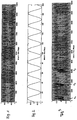
- Fig. 1 shows a speed signal with a constant frequency, for example two megahertz. This signal corresponds in principle to the input signal in a single ultrasonic CW Doppler measurement. This signal is generated constantly continuously continuously with constant frequency.
- Fig. 2 shows a position signal also with constant frequency, which is generated alternately with pause times.
- the frequency here is for example at four megahertz.
- pulses are generated and emitted with this signal, for example pulses of a length of 2 ⁇ s. Based on the time until the detection of echoes on a pulse, conclusions can be drawn on the reflection point, thus on the depth.
- the problem is that for a good resolution short wave packets are required, which in turn contain a small number of waves.
- the accuracy of the speed measurement becomes worse via the Doppler effect.
- Fig. 3 shows a mixed signal from the speed signal according to Fig. 1 and the position signal according to Fig. 2 ,
- t 1 , t 2 and t 3 each have a pulse according to the position signal Fig. 2 from the speed signal Fig. 1 added.
- the mathematical operation of admixture is basically arbitrary.
- the method at this point corresponds to the simultaneous performance of both an ultrasonic CW measurement and an ultrasonic PUL measurement.
- the mixed signal is transmitted via a transmitter in the direction of the object to be examined or of the medium to be examined. From there, the mixed signal is reflected and received as an echo signal.
- the received echo signal is in Fig. 4 shown.
- Fig. 5 shows the echo signal filtered to 2 megahertz Fig. 4 , 2 Megahertz corresponds exactly to the frequency of the speed signal Fig. 1 , about which the speed is to be determined.
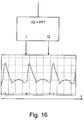
- This filtered echo signal then turns off with the transmitted speed signal Fig. 1 and subjected to an FFT analysis in order to arrive at the speed to be determined via the frequency changes and the Doppler effect (see illustration Fig. 16 ).
- the speed is determined continuously without interruptions. With this method, there are no dead times when the speed remains unknown.
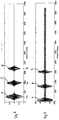
- Fig. 6 this indicates the frequency of the position signal Fig. 2 , here 4 megahertz, filtered echo signal off Fig. 4 , Recognizable here are three echo packets 4, 5 and 6.
- About the echo delay t 4 , t 5 and t 6 is a Conclusion on the position or depth of the reflective object or medium possible.
- the high-precision speed information from the signal in accordance with Fig. 5 receive and continue the position information from the signal according to Fig. 6 , Thus, both sizes are continuously available with one measurement.
- Fig. 7 shows the echo signal Fig. 4 correlates with the position signal Fig. 2 ,
- Fig. 8 shows a speed signal according to a second embodiment with a constant frequency of here, for example 8 megahertz.
- the signal is continuously generated and transmitted continuously at this frequency.
- Fig. 9 shows a position signal according to the second embodiment.
- the signal may be continuously generated and transmitted continuously, but may also be generated or transmitted at intervals of time alternating with a pause.
- the position signal is frequency modulated, initially with two megahertz increasing linearly to four megahertz and then decreasing linearly to two megahertz. After the generation of such a frequency ramp, the signal is first suspended for a pause time and then generated or transmitted again for the duration of the frequency ramp.
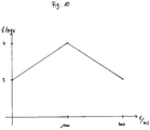
- Fig. 10 shows the frequency modulation function of the position signal Fig. 9 .
- the linear increase from initially two megahertz to four megahertz and towards the end of the ramp drop to two megahertz is recognizable.
- the choice of the modulation function is arbitrary. Barriers may be imposed, for example, by mechanical constraints on reaction delays in piezocrystal generators, but this would be unproblematic in the generation of electromagnetic waves.
- Fig. 11 shows a mixed signal from the speed signal Fig. 8 and position signal after Fig. 9 , This mixed signal is then on a transmitter to be sent in the direction of the medium / object to be examined as in the first embodiment.
- Fig. 12 shows this after transmission of the mixed signal according to Fig. 11 echo signal reflected from the medium / object.
- the evaluation by means of Doppler shift can be done on this signal - just like on the signal Fig. 4 - if necessary after filtering on the frequency of the signal Fig. 8 - To get to the speed of the medium / object.
- Fig. 13 shows the echo signal Fig. 12 correlates with the position signal Fig. 9 ,
- the resolution depends on the quality of the correlation, thus on the uniqueness of the label in the position signal. The better the position signal correlates, the better the resolution in this signal.
- Fig. 14 shows the structure of an apparatus with which the measuring method of the present invention can be performed.
- the speed signal generator 10 for example a CW signal generator, generates a constant frequency signal of eight megahertz FIG. 8th
- the position signal generator 11, for example an FM signal generator, generates a position signal with frequency modulated from two to four megahertz Fig. 9 , Both signals are mixed in a mixing member 12 and passed to a transmitter 14 after amplification in the amplifier 13.
- the transmitter 14 sends the sound waves 15 in the direction of the medium / object 16 to be examined, at which the sound waves 15 experience a reflection.
- the reflected sound waves 17 then pass to a receiver 18 which directs the received echo signal for amplification in the amplifier 19 for evaluation.
- the speed evaluation takes place in consideration of the speed signal (generated by the signal generator 10) in a mixer 20, and the obtained speed information is sent to a presentation member 21.
- the position evaluation takes place in consideration of the position signal generated by the position signal generator 11 in a correlator 22 or the like.
- the position evaluation takes place inter alia by cross-correlation with the position signal. From the result signal, as described above, the position information can be derived.
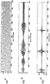
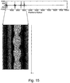
- Fig. 15 Fig. 12 shows a display possibility similar to a signal Fig. 13 .
- this pulsation becomes visible by changing the transit times of the echo packets.
- the duration of the echo packets and thus the position information of the reflection sites, such as the vessel walls, can be applied with an image brightness over time and displayed in a so-called. M-mode.
- the practitioner receives continuous information about the vessel width or depth / position.
- Fig. 16 a further representation of the velocity information obtained from the velocity evaluation is shown.
- the speed information is obtained, for example, after performing a Fourier transformation as a real and imaginary part and plotted over time.
- the black line reflects the number of particles and the shading the velocities of the particles.
- both the speed information and the position information can be displayed simultaneously without dead times. It can be seen how many particles are how fast and at what depth this river is to be assumed. It is even possible to assign the flow to different blood vessels if, for example, there are several blood vessels in the measuring field.
Landscapes
- Engineering & Computer Science (AREA)
- Health & Medical Sciences (AREA)
- Physics & Mathematics (AREA)
- Life Sciences & Earth Sciences (AREA)
- Radar, Positioning & Navigation (AREA)
- Remote Sensing (AREA)
- Pathology (AREA)
- Heart & Thoracic Surgery (AREA)
- Veterinary Medicine (AREA)
- Computer Networks & Wireless Communication (AREA)
- Biophysics (AREA)
- Nuclear Medicine, Radiotherapy & Molecular Imaging (AREA)
- Acoustics & Sound (AREA)
- Radiology & Medical Imaging (AREA)
- Biomedical Technology (AREA)
- General Physics & Mathematics (AREA)
- Medical Informatics (AREA)
- Molecular Biology (AREA)
- Surgery (AREA)
- Animal Behavior & Ethology (AREA)
- General Health & Medical Sciences (AREA)
- Public Health (AREA)
- Hematology (AREA)
- Ultra Sonic Daignosis Equipment (AREA)
Applications Claiming Priority (1)
| Application Number | Priority Date | Filing Date | Title |
|---|---|---|---|
| DE102009012821A DE102009012821A1 (de) | 2009-03-13 | 2009-03-13 | Verfahren zur simultanen Bestimmung von Position und Geschwindigkeit von Objekten |
Publications (2)
| Publication Number | Publication Date |
|---|---|
| EP2228013A1 EP2228013A1 (de) | 2010-09-15 |
| EP2228013B1 true EP2228013B1 (de) | 2016-04-13 |
Family
ID=42244355
Family Applications (1)
| Application Number | Title | Priority Date | Filing Date |
|---|---|---|---|
| EP10153336.2A Active EP2228013B1 (de) | 2009-03-13 | 2010-02-11 | Verfahren zur simultanen Bestimmung von Position und Geschwindigkeit von Objekten |
Country Status (5)
| Country | Link |
|---|---|
| US (1) | US20100234732A1 (pl) |
| EP (1) | EP2228013B1 (pl) |
| DE (1) | DE102009012821A1 (pl) |
| ES (1) | ES2575537T3 (pl) |
| PL (1) | PL2228013T3 (pl) |
Families Citing this family (1)
| Publication number | Priority date | Publication date | Assignee | Title |
|---|---|---|---|---|
| TWI482613B (zh) | 2011-12-27 | 2015-05-01 | Ind Tech Res Inst | 訊號分析方法、超音波影像分析方法以及超音波成像系統 |
Family Cites Families (6)
| Publication number | Priority date | Publication date | Assignee | Title |
|---|---|---|---|---|
| DE3414159A1 (de) * | 1984-04-14 | 1985-10-24 | Licentia Patent-Verwaltungs-Gmbh, 6000 Frankfurt | Radargeraet |
| SE0101320L (sv) * | 2001-04-02 | 2002-02-19 | Saab Ab | Metod och signalsändtagare för fjärrinmätning medelst repetitiv sonderingssignal samt gruppantennsystem innefattande signalsändtagare |
| SE516728C2 (sv) * | 2001-04-02 | 2002-02-19 | Saab Ab | Metod och signalsändtagare för brusmodulerad fjärrinmätning samt gruppantennsystem innefattande signalsändtagare |
| US7244234B2 (en) * | 2003-11-11 | 2007-07-17 | Soma Development Llc | Ultrasound guided probe device and method of using same |
| WO2005098471A2 (en) * | 2004-04-05 | 2005-10-20 | Weibel Scientific A/S | System and method for radar detection of an object |
| US8038622B2 (en) * | 2007-08-03 | 2011-10-18 | Innoscion, Llc | Wired and wireless remotely controlled ultrasonic transducer and imaging apparatus |
-
2009
- 2009-03-13 DE DE102009012821A patent/DE102009012821A1/de not_active Ceased
-
2010
- 2010-02-11 PL PL10153336.2T patent/PL2228013T3/pl unknown
- 2010-02-11 EP EP10153336.2A patent/EP2228013B1/de active Active
- 2010-02-11 ES ES10153336.2T patent/ES2575537T3/es active Active
- 2010-03-11 US US12/721,767 patent/US20100234732A1/en not_active Abandoned
Also Published As
| Publication number | Publication date |
|---|---|
| DE102009012821A1 (de) | 2010-09-16 |
| PL2228013T3 (pl) | 2016-09-30 |
| ES2575537T3 (es) | 2016-06-29 |
| US20100234732A1 (en) | 2010-09-16 |
| EP2228013A1 (de) | 2010-09-15 |
Similar Documents
| Publication | Publication Date | Title |
|---|---|---|
| EP3856038B1 (de) | Verfahren und system zur bestimmung einer strömungsgeschwindigkeit eines durch ein implantiertes, vaskuläres unterstützungssystem strömenden fluids | |
| DE60026471T2 (de) | Akustischer Blitz zum Erhöhen der Penetration | |
| DE3625041C2 (pl) | ||
| EP0204192B1 (de) | Schaltungsanordnung zum Erfassen der Herzschlagsbewegung | |
| DE60315092T2 (de) | Ultraschallvorrichtung und Verfahren zur Messung der Geschwindigkeit von menschlichem Gewebe mittels des Doppler Effektes | |
| DE60215406T2 (de) | Verfahren und Vorrichtung zur Ultraschallabbildung | |
| DE69214023T2 (de) | Filter zur Festechounterdrückung für ein Ultraschalldopplersystem | |
| DE102008042278A1 (de) | Verfahren zur zerstörungsfreien Ultraschalluntersuchung sowie Vorrichtung zur Durchführung des Verfahrens | |
| EP3071989B1 (de) | Verfahren und eine vorrichtung zur messung einer relativgeschwindigkeit mittels eines akustischen sensors | |
| EP2676131B1 (de) | Verfahren zur reduktion von ultraschalldaten | |
| EP3324207A1 (de) | Verfahren zum betreiben eines ultraschallsystems | |
| DE69017102T2 (de) | Diagnose-Ultraschallgerät. | |
| DE10308595A1 (de) | Verfahren und Vorrichtung zur spektralen Verformungsratenvisualisierung | |
| DE102011115691B4 (de) | Verfahren zur Ermittlung der Viskosität eines strömenden oder ruhenden Fluids | |
| DE2513143A1 (de) | Geschwindigkeitsmessgeraet | |
| DE19733091B4 (de) | Vorrichtung und Verfahren zur Emboliedetektion | |
| DE10036565C2 (de) | Vorrichtung zur Feststellung der Änderung der Dichte eines Mediums | |
| DE69222401T2 (de) | Ultraschallechograph zur Messung hoher Geschwindigkeiten von Blutströmungen | |
| EP2228013A1 (de) | Verfahren zur simultanen Bestimmung von Position und Geschwindigkeit von Objekten | |
| DE69109318T2 (de) | Echographievorrichtung zur Messung der Blutströmung und zur Geschwindigkeitsmessung von bewegten Organen mit erhöhter messbarer Geschwindigkeit. | |
| DE202008003245U1 (de) | Vorrichtung zur Ultraschall-Messung von Blutfluß | |
| DE19740549C2 (de) | Verfahren zur Messung der Strömungscharakteristik und anderer Prozeßparameter | |
| EP2607919A1 (de) | Verfahren zum berührungslosen Detektieren eines Objekts in einer Umgebung eines Fahrzeugs, Fahrerassistenzeinrichtung mit einer Ultraschallsensoreinrichtung und Fahrzeug mit einer derartigen Fahrerassistenzeinrichtung | |
| EP2803061B1 (de) | Verfahren zur abtastung der umgebung eines sich bewegenden fahrzeugs | |
| EP3301410B1 (de) | Lokalisieren eines ereignisses in einem sensorsignal |
Legal Events
| Date | Code | Title | Description |
|---|---|---|---|
| PUAI | Public reference made under article 153(3) epc to a published international application that has entered the european phase |
Free format text: ORIGINAL CODE: 0009012 |
|
| AK | Designated contracting states |
Kind code of ref document: A1 Designated state(s): AT BE BG CH CY CZ DE DK EE ES FI FR GB GR HR HU IE IS IT LI LT LU LV MC MK MT NL NO PL PT RO SE SI SK SM TR |
|
| AX | Request for extension of the european patent |
Extension state: AL BA RS |
|
| 17P | Request for examination filed |
Effective date: 20110203 |
|
| 17Q | First examination report despatched |
Effective date: 20140509 |
|
| RAP1 | Party data changed (applicant data changed or rights of an application transferred) |
Owner name: WROBEL, MIROSLAW |
|
| RIN1 | Information on inventor provided before grant (corrected) |
Inventor name: WROBEL, MIROSLAW |
|
| REG | Reference to a national code |
Ref country code: DE Ref legal event code: R079 Ref document number: 502010011414 Country of ref document: DE Free format text: PREVIOUS MAIN CLASS: A61B0008060000 Ipc: A61B0008120000 |
|
| GRAP | Despatch of communication of intention to grant a patent |
Free format text: ORIGINAL CODE: EPIDOSNIGR1 |
|
| RIC1 | Information provided on ipc code assigned before grant |
Ipc: A61B 8/06 20060101ALI20150813BHEP Ipc: A61B 8/08 20060101ALI20150813BHEP Ipc: A61B 8/12 20060101AFI20150813BHEP Ipc: G01S 13/58 20060101ALI20150813BHEP Ipc: G01S 15/58 20060101ALI20150813BHEP Ipc: G01S 15/89 20060101ALI20150813BHEP |
|
| INTG | Intention to grant announced |
Effective date: 20150914 |
|
| GRAS | Grant fee paid |
Free format text: ORIGINAL CODE: EPIDOSNIGR3 |
|
| GRAA | (expected) grant |
Free format text: ORIGINAL CODE: 0009210 |
|
| AK | Designated contracting states |
Kind code of ref document: B1 Designated state(s): AT BE BG CH CY CZ DE DK EE ES FI FR GB GR HR HU IE IS IT LI LT LU LV MC MK MT NL NO PL PT RO SE SI SK SM TR |
|
| REG | Reference to a national code |
Ref country code: GB Ref legal event code: FG4D Free format text: NOT ENGLISH |
|
| REG | Reference to a national code |
Ref country code: AT Ref legal event code: REF Ref document number: 789183 Country of ref document: AT Kind code of ref document: T Effective date: 20160415 Ref country code: CH Ref legal event code: EP |
|
| REG | Reference to a national code |
Ref country code: IE Ref legal event code: FG4D Free format text: LANGUAGE OF EP DOCUMENT: GERMAN |
|
| REG | Reference to a national code |
Ref country code: CH Ref legal event code: NV Representative=s name: E. BLUM AND CO. AG PATENT- UND MARKENANWAELTE , CH |
|
| REG | Reference to a national code |
Ref country code: DE Ref legal event code: R096 Ref document number: 502010011414 Country of ref document: DE |
|
| REG | Reference to a national code |
Ref country code: ES Ref legal event code: FG2A Ref document number: 2575537 Country of ref document: ES Kind code of ref document: T3 Effective date: 20160629 |
|
| REG | Reference to a national code |
Ref country code: NL Ref legal event code: FP |
|
| REG | Reference to a national code |
Ref country code: LT Ref legal event code: MG4D |
|
| PG25 | Lapsed in a contracting state [announced via postgrant information from national office to epo] |
Ref country code: LT Free format text: LAPSE BECAUSE OF FAILURE TO SUBMIT A TRANSLATION OF THE DESCRIPTION OR TO PAY THE FEE WITHIN THE PRESCRIBED TIME-LIMIT Effective date: 20160413 Ref country code: FI Free format text: LAPSE BECAUSE OF FAILURE TO SUBMIT A TRANSLATION OF THE DESCRIPTION OR TO PAY THE FEE WITHIN THE PRESCRIBED TIME-LIMIT Effective date: 20160413 Ref country code: NO Free format text: LAPSE BECAUSE OF FAILURE TO SUBMIT A TRANSLATION OF THE DESCRIPTION OR TO PAY THE FEE WITHIN THE PRESCRIBED TIME-LIMIT Effective date: 20160713 |
|
| PG25 | Lapsed in a contracting state [announced via postgrant information from national office to epo] |
Ref country code: GR Free format text: LAPSE BECAUSE OF FAILURE TO SUBMIT A TRANSLATION OF THE DESCRIPTION OR TO PAY THE FEE WITHIN THE PRESCRIBED TIME-LIMIT Effective date: 20160714 Ref country code: HR Free format text: LAPSE BECAUSE OF FAILURE TO SUBMIT A TRANSLATION OF THE DESCRIPTION OR TO PAY THE FEE WITHIN THE PRESCRIBED TIME-LIMIT Effective date: 20160413 Ref country code: SE Free format text: LAPSE BECAUSE OF FAILURE TO SUBMIT A TRANSLATION OF THE DESCRIPTION OR TO PAY THE FEE WITHIN THE PRESCRIBED TIME-LIMIT Effective date: 20160413 Ref country code: PT Free format text: LAPSE BECAUSE OF FAILURE TO SUBMIT A TRANSLATION OF THE DESCRIPTION OR TO PAY THE FEE WITHIN THE PRESCRIBED TIME-LIMIT Effective date: 20160816 Ref country code: LV Free format text: LAPSE BECAUSE OF FAILURE TO SUBMIT A TRANSLATION OF THE DESCRIPTION OR TO PAY THE FEE WITHIN THE PRESCRIBED TIME-LIMIT Effective date: 20160413 |
|
| REG | Reference to a national code |
Ref country code: DE Ref legal event code: R097 Ref document number: 502010011414 Country of ref document: DE |
|
| PG25 | Lapsed in a contracting state [announced via postgrant information from national office to epo] |
Ref country code: DK Free format text: LAPSE BECAUSE OF FAILURE TO SUBMIT A TRANSLATION OF THE DESCRIPTION OR TO PAY THE FEE WITHIN THE PRESCRIBED TIME-LIMIT Effective date: 20160413 Ref country code: SK Free format text: LAPSE BECAUSE OF FAILURE TO SUBMIT A TRANSLATION OF THE DESCRIPTION OR TO PAY THE FEE WITHIN THE PRESCRIBED TIME-LIMIT Effective date: 20160413 Ref country code: CZ Free format text: LAPSE BECAUSE OF FAILURE TO SUBMIT A TRANSLATION OF THE DESCRIPTION OR TO PAY THE FEE WITHIN THE PRESCRIBED TIME-LIMIT Effective date: 20160413 Ref country code: EE Free format text: LAPSE BECAUSE OF FAILURE TO SUBMIT A TRANSLATION OF THE DESCRIPTION OR TO PAY THE FEE WITHIN THE PRESCRIBED TIME-LIMIT Effective date: 20160413 Ref country code: RO Free format text: LAPSE BECAUSE OF FAILURE TO SUBMIT A TRANSLATION OF THE DESCRIPTION OR TO PAY THE FEE WITHIN THE PRESCRIBED TIME-LIMIT Effective date: 20160413 |
|
| PLBE | No opposition filed within time limit |
Free format text: ORIGINAL CODE: 0009261 |
|
| STAA | Information on the status of an ep patent application or granted ep patent |
Free format text: STATUS: NO OPPOSITION FILED WITHIN TIME LIMIT |
|
| REG | Reference to a national code |
Ref country code: FR Ref legal event code: PLFP Year of fee payment: 8 |
|
| PG25 | Lapsed in a contracting state [announced via postgrant information from national office to epo] |
Ref country code: SM Free format text: LAPSE BECAUSE OF FAILURE TO SUBMIT A TRANSLATION OF THE DESCRIPTION OR TO PAY THE FEE WITHIN THE PRESCRIBED TIME-LIMIT Effective date: 20160413 |
|
| 26N | No opposition filed |
Effective date: 20170116 |
|
| PG25 | Lapsed in a contracting state [announced via postgrant information from national office to epo] |
Ref country code: SI Free format text: LAPSE BECAUSE OF FAILURE TO SUBMIT A TRANSLATION OF THE DESCRIPTION OR TO PAY THE FEE WITHIN THE PRESCRIBED TIME-LIMIT Effective date: 20160413 Ref country code: BE Free format text: LAPSE BECAUSE OF NON-PAYMENT OF DUE FEES Effective date: 20170228 |
|
| PG25 | Lapsed in a contracting state [announced via postgrant information from national office to epo] |
Ref country code: MC Free format text: LAPSE BECAUSE OF FAILURE TO SUBMIT A TRANSLATION OF THE DESCRIPTION OR TO PAY THE FEE WITHIN THE PRESCRIBED TIME-LIMIT Effective date: 20160413 |
|
| REG | Reference to a national code |
Ref country code: IE Ref legal event code: MM4A |
|
| PG25 | Lapsed in a contracting state [announced via postgrant information from national office to epo] |
Ref country code: LU Free format text: LAPSE BECAUSE OF NON-PAYMENT OF DUE FEES Effective date: 20170211 |
|
| REG | Reference to a national code |
Ref country code: BE Ref legal event code: MM Effective date: 20170228 |
|
| REG | Reference to a national code |
Ref country code: FR Ref legal event code: PLFP Year of fee payment: 9 |
|
| PG25 | Lapsed in a contracting state [announced via postgrant information from national office to epo] |
Ref country code: IE Free format text: LAPSE BECAUSE OF NON-PAYMENT OF DUE FEES Effective date: 20170211 |
|
| PG25 | Lapsed in a contracting state [announced via postgrant information from national office to epo] |
Ref country code: MT Free format text: LAPSE BECAUSE OF FAILURE TO SUBMIT A TRANSLATION OF THE DESCRIPTION OR TO PAY THE FEE WITHIN THE PRESCRIBED TIME-LIMIT Effective date: 20160413 |
|
| PG25 | Lapsed in a contracting state [announced via postgrant information from national office to epo] |
Ref country code: HU Free format text: LAPSE BECAUSE OF FAILURE TO SUBMIT A TRANSLATION OF THE DESCRIPTION OR TO PAY THE FEE WITHIN THE PRESCRIBED TIME-LIMIT; INVALID AB INITIO Effective date: 20100211 |
|
| PG25 | Lapsed in a contracting state [announced via postgrant information from national office to epo] |
Ref country code: BG Free format text: LAPSE BECAUSE OF FAILURE TO SUBMIT A TRANSLATION OF THE DESCRIPTION OR TO PAY THE FEE WITHIN THE PRESCRIBED TIME-LIMIT Effective date: 20160413 |
|
| PG25 | Lapsed in a contracting state [announced via postgrant information from national office to epo] |
Ref country code: CY Free format text: LAPSE BECAUSE OF NON-PAYMENT OF DUE FEES Effective date: 20160413 |
|
| PG25 | Lapsed in a contracting state [announced via postgrant information from national office to epo] |
Ref country code: MK Free format text: LAPSE BECAUSE OF FAILURE TO SUBMIT A TRANSLATION OF THE DESCRIPTION OR TO PAY THE FEE WITHIN THE PRESCRIBED TIME-LIMIT Effective date: 20160413 |
|
| PG25 | Lapsed in a contracting state [announced via postgrant information from national office to epo] |
Ref country code: TR Free format text: LAPSE BECAUSE OF FAILURE TO SUBMIT A TRANSLATION OF THE DESCRIPTION OR TO PAY THE FEE WITHIN THE PRESCRIBED TIME-LIMIT Effective date: 20160413 |
|
| PGFP | Annual fee paid to national office [announced via postgrant information from national office to epo] |
Ref country code: PL Payment date: 20200115 Year of fee payment: 11 Ref country code: IT Payment date: 20200221 Year of fee payment: 11 Ref country code: AT Payment date: 20200218 Year of fee payment: 11 Ref country code: ES Payment date: 20200320 Year of fee payment: 11 Ref country code: NL Payment date: 20200220 Year of fee payment: 11 |
|
| PG25 | Lapsed in a contracting state [announced via postgrant information from national office to epo] |
Ref country code: IS Free format text: LAPSE BECAUSE OF FAILURE TO SUBMIT A TRANSLATION OF THE DESCRIPTION OR TO PAY THE FEE WITHIN THE PRESCRIBED TIME-LIMIT Effective date: 20160813 |
|
| REG | Reference to a national code |
Ref country code: AT Ref legal event code: MM01 Ref document number: 789183 Country of ref document: AT Kind code of ref document: T Effective date: 20210211 |
|
| PG25 | Lapsed in a contracting state [announced via postgrant information from national office to epo] |
Ref country code: AT Free format text: LAPSE BECAUSE OF NON-PAYMENT OF DUE FEES Effective date: 20210211 |
|
| REG | Reference to a national code |
Ref country code: NL Ref legal event code: MM Effective date: 20210301 |
|
| PG25 | Lapsed in a contracting state [announced via postgrant information from national office to epo] |
Ref country code: NL Free format text: LAPSE BECAUSE OF NON-PAYMENT OF DUE FEES Effective date: 20210301 |
|
| PG25 | Lapsed in a contracting state [announced via postgrant information from national office to epo] |
Ref country code: IT Free format text: LAPSE BECAUSE OF NON-PAYMENT OF DUE FEES Effective date: 20210211 |
|
| REG | Reference to a national code |
Ref country code: ES Ref legal event code: FD2A Effective date: 20220510 |
|
| PG25 | Lapsed in a contracting state [announced via postgrant information from national office to epo] |
Ref country code: ES Free format text: LAPSE BECAUSE OF NON-PAYMENT OF DUE FEES Effective date: 20210212 |
|
| PG25 | Lapsed in a contracting state [announced via postgrant information from national office to epo] |
Ref country code: PL Free format text: LAPSE BECAUSE OF NON-PAYMENT OF DUE FEES Effective date: 20210211 |
|
| PGFP | Annual fee paid to national office [announced via postgrant information from national office to epo] |
Ref country code: GB Payment date: 20240222 Year of fee payment: 15 Ref country code: CH Payment date: 20240301 Year of fee payment: 15 |
|
| PGFP | Annual fee paid to national office [announced via postgrant information from national office to epo] |
Ref country code: FR Payment date: 20240222 Year of fee payment: 15 |
|
| PGFP | Annual fee paid to national office [announced via postgrant information from national office to epo] |
Ref country code: DE Payment date: 20250423 Year of fee payment: 16 |
|
| REG | Reference to a national code |
Ref country code: CH Ref legal event code: PL |
|
| PG25 | Lapsed in a contracting state [announced via postgrant information from national office to epo] |
Ref country code: CH Free format text: LAPSE BECAUSE OF NON-PAYMENT OF DUE FEES Effective date: 20250228 |
|
| GBPC | Gb: european patent ceased through non-payment of renewal fee |
Effective date: 20250211 |
|
| PG25 | Lapsed in a contracting state [announced via postgrant information from national office to epo] |
Ref country code: GB Free format text: LAPSE BECAUSE OF NON-PAYMENT OF DUE FEES Effective date: 20250211 |
|
| PG25 | Lapsed in a contracting state [announced via postgrant information from national office to epo] |
Ref country code: FR Free format text: LAPSE BECAUSE OF NON-PAYMENT OF DUE FEES Effective date: 20250228 |