EP2227379B1 - Verfahren zur herstellung eines faserverbundwerkstoff-vorformlings aus einem laminat mit zumindest zwei prepreg-lagen sowie herstellungsvorrichtung für ein derartiges verfahren - Google Patents
Verfahren zur herstellung eines faserverbundwerkstoff-vorformlings aus einem laminat mit zumindest zwei prepreg-lagen sowie herstellungsvorrichtung für ein derartiges verfahren Download PDFInfo
- Publication number
- EP2227379B1 EP2227379B1 EP08856106A EP08856106A EP2227379B1 EP 2227379 B1 EP2227379 B1 EP 2227379B1 EP 08856106 A EP08856106 A EP 08856106A EP 08856106 A EP08856106 A EP 08856106A EP 2227379 B1 EP2227379 B1 EP 2227379B1
- Authority
- EP
- European Patent Office
- Prior art keywords
- clamping device
- laminate
- clamping
- edge section
- layers
- Prior art date
- Legal status (The legal status is an assumption and is not a legal conclusion. Google has not performed a legal analysis and makes no representation as to the accuracy of the status listed.)
- Not-in-force
Links
Images


Classifications
-
- B—PERFORMING OPERATIONS; TRANSPORTING
- B29—WORKING OF PLASTICS; WORKING OF SUBSTANCES IN A PLASTIC STATE IN GENERAL
- B29C—SHAPING OR JOINING OF PLASTICS; SHAPING OF MATERIAL IN A PLASTIC STATE, NOT OTHERWISE PROVIDED FOR; AFTER-TREATMENT OF THE SHAPED PRODUCTS, e.g. REPAIRING
- B29C70/00—Shaping composites, i.e. plastics material comprising reinforcements, fillers or preformed parts, e.g. inserts
- B29C70/04—Shaping composites, i.e. plastics material comprising reinforcements, fillers or preformed parts, e.g. inserts comprising reinforcements only, e.g. self-reinforcing plastics
- B29C70/28—Shaping operations therefor
- B29C70/54—Component parts, details or accessories; Auxiliary operations, e.g. feeding or storage of prepregs or SMC after impregnation or during ageing
- B29C70/56—Tensioning reinforcements before or during shaping
-
- B—PERFORMING OPERATIONS; TRANSPORTING
- B29—WORKING OF PLASTICS; WORKING OF SUBSTANCES IN A PLASTIC STATE IN GENERAL
- B29B—PREPARATION OR PRETREATMENT OF THE MATERIAL TO BE SHAPED; MAKING GRANULES OR PREFORMS; RECOVERY OF PLASTICS OR OTHER CONSTITUENTS OF WASTE MATERIAL CONTAINING PLASTICS
- B29B11/00—Making preforms
- B29B11/14—Making preforms characterised by structure or composition
- B29B11/16—Making preforms characterised by structure or composition comprising fillers or reinforcement
-
- B—PERFORMING OPERATIONS; TRANSPORTING
- B29—WORKING OF PLASTICS; WORKING OF SUBSTANCES IN A PLASTIC STATE IN GENERAL
- B29C—SHAPING OR JOINING OF PLASTICS; SHAPING OF MATERIAL IN A PLASTIC STATE, NOT OTHERWISE PROVIDED FOR; AFTER-TREATMENT OF THE SHAPED PRODUCTS, e.g. REPAIRING
- B29C53/00—Shaping by bending, folding, twisting, straightening or flattening; Apparatus therefor
- B29C53/02—Bending or folding
- B29C53/04—Bending or folding of plates or sheets
-
- B—PERFORMING OPERATIONS; TRANSPORTING
- B29—WORKING OF PLASTICS; WORKING OF SUBSTANCES IN A PLASTIC STATE IN GENERAL
- B29C—SHAPING OR JOINING OF PLASTICS; SHAPING OF MATERIAL IN A PLASTIC STATE, NOT OTHERWISE PROVIDED FOR; AFTER-TREATMENT OF THE SHAPED PRODUCTS, e.g. REPAIRING
- B29C70/00—Shaping composites, i.e. plastics material comprising reinforcements, fillers or preformed parts, e.g. inserts
- B29C70/04—Shaping composites, i.e. plastics material comprising reinforcements, fillers or preformed parts, e.g. inserts comprising reinforcements only, e.g. self-reinforcing plastics
- B29C70/28—Shaping operations therefor
- B29C70/54—Component parts, details or accessories; Auxiliary operations, e.g. feeding or storage of prepregs or SMC after impregnation or during ageing
- B29C70/541—Positioning reinforcements in a mould, e.g. using clamping means for the reinforcement
Definitions
- the invention relates to a method for producing a fiber composite (FVW) preform from a laminate having at least two prepreg layers and to a production device for deforming a semifinished product for producing a FVW component according to this method.
- FVW fiber composite
- the EP 1 393 875 A1 describes a method and a mold for forming composite materials.
- a pressing device for forming a laminate structure is taught.
- the pressing device has a pressing tool which has lateral end pieces protruding from a middle section made of an elastic material.
- the pressing tool is moved against an abutment with a laminate structure lying thereon, which is arranged on the counter-layer such that portions lying opposite to one another extend beyond the counter-layer.
- the counter-layer is designed in such a way that, during the pressing movement of the pressing tool, the sections of the laminate structure which extend beyond the counter-layer are pressed down laterally of the counter-layer.
- the elastic end pieces compress the curvature regions of the laminate structure which are formed laterally of the counter-layer with increasing pressing movement in their thickness direction. During the pressing movement, the contact surfaces of the end pieces slide over the surface of the laminate structure facing the same.
- a multi-stage process for producing a structural composite carrier for aircraft is known from DE 60 2005 002 300 T2 known.
- pre-impregnated fiber composites consisting of impregnated reinforcing fibers impregnated with a resin composition while maintaining a defined fiber volume content are used.
- prepregs consisting of impregnated reinforcing fibers impregnated with a resin composition while maintaining a defined fiber volume content.
- the multilayer prepreg laminate is heated to a forming temperature in order to improve the flow properties of the resin mixture.
- the prepreg laminate is reshaped, whereby the laminate layers (laminate layers) of the laminate slide on each other.
- the hot forming of the laminate for example, by means of a single or double diaphragm forming process, press forming or bending process.
- Diaphragm forming processes use a tool mold and a flexible membrane (diaphragm) which cause part deformation to cause deformation of the laminate.
- the press forming process is carried out by compressing heated molds.
- a method and an apparatus for hot working composite plates by means of a bending technique is for example from WO 90/11882 known.
- This conventional bending device uses two bending plates, between which the laminate is arranged.
- a tensile force is applied in the direction of the free plate edge of the laminate by means of a press ram and a pressure roller in order to achieve a tension of the laminate layers.
- a disadvantage of such methods is that the interlaminar sliding of the laminate layers, in particular for large leg lengths and component thicknesses of the fiber composite component, is associated with a high resistance, so that it in the manufacture of the component to a lifting and buckling of the inner Laminate layers can come as a result of compressive stresses on the inner radius of the component.
- the invention is based on the object, a method for producing a FVW preform of a laminate with a total of at least two dry fiber fabric layers, which is held together with binders, and / or with at least two prepreg layers and a manufacturing device for the deformation of a semifinished product for the production to provide a FVW component according to this method, wherein lifting and raising of the inner laminate layers during the forming is prevented.
- the laminate material is not elongated, but bent, in such a way that the laminate layers do not slip or slide against each other or over each other.
- sliding movements between the laminate layers during the forming process and in particular resulting damage to the surface of the laminate structure and thus prevents deterioration of the quality of the component to be produced According to the invention, no or very little sliding movement takes place within the clamping device between the laminate and the clamping device and / or between laminate layers; moreover, the curved region is exposed to the outside.
- the tension in the laminate is created by movement of the form piece transversely to the longitudinal direction of the laminate.
- the manufacturing apparatus for carrying out the method is provided with an actuating device and a movement mechanism with which the fitting can be moved.
- the movement of the first clamping device while exerting a tensile force, comprises a movement of the first clamping device downwards in the direction of the side surface of the shaped piece until the laminate abuts in portions on a first side face facing the first clamping device.
- the angle by which the edge section situated in the first clamping device is rotated relative to the region of the laminate located in front of the first clamping device can be in the range ⁇ 10 degrees equal to the angle in which the second side surface extends with respect to the support surface.
- the first end portion Before clamping the end portion of the laminate in the first clamping device, it may be provided that the first end portion is angled relative to the area adjacent to the end portion to form a curvature area located between these areas and the layers are offset from each other due to the curvature, and that Layers of the first end portion are clamped together in this staggered support in the first clamping device.
- the length of the end portion may be provided so small that a displacement of the position of the end portion takes place without forming a raising of an inner layer.
- the end portion can be angled relative to the area adjacent to the end portion by means of a Umformkems.
- the angling of the end portion relative to the portion adjacent to the end portion can be done by rotating the first clamping device about an axis at which the portion of the laminate received by the first clamping device is angled in its longitudinal direction relative to the region outside and in front of the first clamping device is located.
- a lower clamping force is set, which allows an offset of the layers to each other due to the rotation of the layers.
- the laminate may be an annular segment of an annular preform laminate made by winding a semifinished product onto a winding core.
- the support surface and / or the side surface may be flat.
- the support surface and / or the first side surface may have a curved surface viewed in the pulling direction.
- the support surface and / or the first side surface extending transversely to the direction of pull have three-dimensional contour, so that the preform receives a transverse to the pulling direction seen three-dimensional deformation.
- the second clamping device when moving the first clamping device by means of a further movement mechanism, the second clamping device, which, viewed from the first clamping device, is located beyond a further rounded surface area of the shaped part, in one Direction opposite to the direction of movement of the first clamping device is moved to a point at which the second rounded surface area of the molding, which is located as seen from the first clamping device beyond the first surface area, the laminate between the first rounded surface area and the second clamping device in seen in its longitudinal direction imparts a curvature.
- the movement of the second clamping device can take place simultaneously to the movement of the first clamping device.
- the movement of the further clamping device may also include a movement of the further clamping device in the direction of a second side face of the fitting facing the first side face and facing the second clamping device, until the laminate abuts the second side face in sections.
- the length of the second end portion is so small that an offset of the position of the end portion takes place without forming a throwing of an inner layer. Furthermore, it can be provided in the method that the Angle about the located in the second clamping device edge portion relative to the located in front of the first clamping device region of the laminate in the range ⁇ 10 degrees is equal to the angle at which the second side surface extends relative to the support surface. In the step of angling the second end portion relative to the area adjacent to the end portion, this angling can be done by means of a forming core.
- the bending of the second end portion relative to the portion adjacent to the end portion can be performed by rotating the second clamping device about an axis at which the second end portion of the laminate received by the second clamping device is angled in its longitudinal direction opposite to the portion outside the second clamping device and is located in front of this.
- the second side surface may be formed flat at least in sections or at least in sections may have a curved surface viewed in the pulling direction. Furthermore, the support surface and / or the first side surface can have a three-dimensional contour running transversely to the direction of pull, so that a three-dimensional deformation transversely to the pulling direction is obtained on the preform.
- a drive device is coupled, which is actuated by means of the actuating device and to which the first receiving device is coupled, wherein the movement mechanism and the drive device are designed such that the first receiving device has a predetermined tensile force against the direction points to the second receiving device, can apply and at the same time can perform a movement relative to the fitting receiving.
- the movement performed by the movement mechanics can be located in one plane.
- the drive device may be adapted to exert a tensile force on the laminate during the movement of the movement mechanism by a predetermined amount.
- the tensile force can be applied by means of a spring device, in particular coupled to the drive device, with which a minimum tensile force is maintained during the forming movement.
- the movement mechanism may be designed such that the movement path is adjustable.
- the trajectory can be arcuate.
- the first receiving device may have a rotating device, with which the first receiving device is rotatable about an axis which extends transversely to the connection between the first and the second receiving device.
- a movement mechanism is coupled to the second receiving device, which is controllable by means of an actuating device, wherein the movement mechanism and the drive device are designed such that the second receiving device apply a predetermined tensile force against the direction facing the first receiving device can and simultaneously perform a movement relative to the fitting receiving.
- the movement of the second receiving device executed by the movement mechanism is located in one plane.
- the drive device of the second receiving device may be designed so that it is suitable to apply a tensile force to the laminate with a predetermined amount exercise.
- the drive device of the second receiving device may comprise a spring device, with which a tensile force is applied against the first receiving device, so that a minimum tensile force is maintained during the forming.
- the movement mechanism of the second receiving device can be designed such that the movement path is adjustable.
- the manufacturing device is designed such that a tensile force is exerted in the direction of the exposed before the respective clamping device or receiving device portion and at the same time a predetermined trajectory is performed.
- the movement path of the second receiving device is arcuate.
- the second receiving device may comprise a rotating device with which the second receiving device is rotatable about an axis which extends transversely to the connection between the first and the second receiving device.
- the actuating device and the movement mechanism with the aforementioned alternatives can be provided in an analogous manner for the movement of the molding.
- a fiber composite material (FVW) preform 1 which in the FIGS. 4 and 8th is shown in a form to be produced, by means of the movement of a clamping device (16, 17) at least one clamped end portion 44 and 45 by an investment on a rounded surface portion 58 and 59 while applying a tensile force F transverse to the axis of rotation of the clamping device ( Figures 3 as well as 7 and 8).
- a pre-curvature of the laminate in particular in the vicinity of a curvature region 68, 69 (FIG. FIG. 8 ), as shown in exemplary embodiments in the FIGS. 1, 2 and Figs. 5, 6 are shown.
- a laminate 4, 40 which has a plurality or a plurality of laminate layers or layers 2a, 2b, 2c, for example in a state which in the Figures 2 or 6 and 7 is deformed.
- the starting laminate is a laminate comprising at least two dry fiber fabric layers in total, which is held together with binders and / or uses prepreg layers.
- the following is briefly spoken of laminate layers.
- the deformation may be a deformation and, in particular, may additionally be a three-dimensional deformation of the layers of the starting laminate.
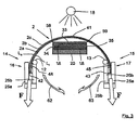
- the laminate 4 used for the subsequent forming steps is produced beforehand in a winding process ( FIG. 1 ), in which, for example, a fiber composite material is wound onto a winding core 6, which in particular can have a circular cross section ( FIG. 1 ).
- the winding process can be carried out in various ways. It can be provided to first guide an endless fiber, a strand or a band through an impregnating bath, to wet it with the matrix material and then to wind it around the winding core 6. Alternatively, prepreg tapes are wound, which are then cured.
- the core with non-saturated composites, which are subsequently impregnated in a resin injection process to form the laminate.
- the layer sequence and number of applied laminate layers 2a, 2b, 2c depends on the requirements of the component to be produced.
- the fiber profile is adapted to the load path of the component, so that the production of lightweight, high-strength structures is possible.
- the winding process and thus the production of the starting preform 2 can be carried out largely automated.
- FIG. 2 shows a side view of a segment of the after FIG. 1 wound starting parison 2 off FIG. 1 , which is separated from the annular preform produced in the winding process after winding in a plurality and preferably in two, each forming a laminate 4 half-rings and removed from the winding body 6.
- a laminate ring segment as the starting preform 2 for the forming process according to the FIG. 3 are in Seen longitudinally of the curvature, the end portions 44, 45 are rotated relative to a central region 41 in the orientation of their longitudinal directions.
- the preform laminate may also be made as shown in FIGS. 5 and 6 or otherwise formed.
- At least one end portion 44, 45 is angled relative to a region 46, 47, which is located adjacent to this end portion 44, 45 to the central region 41, so that a located between the end portion 44 and 45 area to form a angled between these areas curvature region 48 and 49 is angled.
- the preform laminate may in particular have rounded surface regions 36, 37.
- the cross-sectional shape of the molding 20 may be provided according to the application and the required shape of the FVW preform 1.
- the fitting 20 could also have a trapezoidal, triangular, or hexagonal cross-sectional shape.
- This step may also be provided with two, seen in the longitudinal direction or machining direction opposite to this located second end portions, as shown in the FIGS. 5 and 6 is shown. Since, in this step, the respective end section is not clamped or clamped in the cross-sectional direction, the layers can offset one another in their longitudinal direction in accordance with their respective radius in the region of curvature 48 and 49, respectively.
- a starting preform 2 with an angling away of the end section 44 or 45 with respect to the region lying adjacent to the end section 46 or 47 can also, after clamping an edge section in a clamping device 16, 17, by Rotation of the respective clamping device take place about an axis in which the portion of the laminate received by the first clamping device 16 is angled in its longitudinal direction relative to the region which is outside the first clamping device and before this, wherein a lower, ie maximum allowable clamping force is set, which allows a displacement of the layers to each other due to the rotation of the layers.
- an output preform 2 at least one exposed end section 44 or 45 is subsequently clamped or clamped with layers which are offset relative to a starting position with a different curvature and in particular with a planar course, at least in these areas. that the layers of the end section can not offset each other in further process steps.
- steps for forming a starting preform 2 which already has a curvature 48, 49, the risk of the formation of dents or of wrinkles or folds in the curvature region 48, 49 at the inner layers Li, ie the layers with smaller diameter, compared to further outlying layers La further reduced in the curvature region radii.
- Vorfomling 2 for the process even after the FIGS. 5 and 6 can also be a preform segment after the FIG. 2 be used.
- the forming of the FVW preform 1 can be carried out by means of a hot forming process in order to obtain the according to FIG. 5 to transform over projecting end portions 44, 45 of the laminate 40.
- the hot forming of the plate-shaped laminate 40 may be accomplished, for example, by a single or double diaphragm forming process. In this case, slide the layers 2a, 2b, 2c of the laminate 40 to each other, wherein the displacements at leg ends 42, 43 expire, so that in the FIG. 6 shown "book effect" at the leg ends 42, 43 of the approximately U-shaped FVW preform 1 occurs.
- the diaphragm forming process a distinction is made between the simple (SD method) and the double-diaphragm method (DD method) with a diaphragm or two diaphragms.
- the diaphragm is in each case a flexible membrane (not shown), for example a Tygavac® LRB100 or Mosites membrane, which separates a vacuum-evacuated space from the atmosphere.
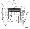
- the forming core 50 is placed on a vacuum table.
- the laminate 40 is positioned on the molding 20 in the desired position, fixed and warmed by means of a heater 18 (see FIG. 5 ). For heating the laminate 40, it is further convectively irradiated with heat from above.
- the heat is first transferred by heat radiation to the upper diaphragm and from there by heat conduction through the membrane into the clutch.
- a heat source ceramic emitters bulbs or IR emitters are preferably used.
- the forming table can be heated from below, ie from the shaped piece 20, eg via heat radiators, for example IR radiators. Thereafter, the diaphragm is placed on the entire structure and connected airtight with the vacuum table. Subsequently, a vacuum is generated by a vacuum line between the diaphragm and the vacuum table, so that the ambient pressure presses the laminate 40 to the fitting 20 and deformed in this way.
- the double diaphragm method differs from the single diaphragm method essentially in that the laminate 40 is positioned between two diaphragms and vacuum evacuated. In this way, the individual layers of the laminate 40 are already fixed to each other. The entire package of the two diaphragms and the scrim is then heated and reshaped, as already explained by the SD method.
- the optionally provided hot-forming of the FVW preform 1 can be carried out according to a further embodiment of the invention by means of a press or bending forming process (not shown).
- a press forming process for forming the preform 1 the laminate 40 is formed between a negative and a positive tool by pressing under the action of temperature.
- a laminate 40 lying on a table is folded over around an edge.
- plates are used which comprise the laminate on the top and bottom without heavy pressure. Subsequently, an end portion 44, 45 of the laminate 40 is bent around the edge by means of a pivotal movement of the plates.
- the pre-curved or non-pre-curved preform 1 is clamped by means of the movement of a clamping device 16, 17, in which at least one end portion 44, 45 is clamped, in particular a region seen in the longitudinal direction LR inside or in front of the clamping device, ie in the direction of the central region 46 or 47 bent by contact with a rounded surface area 58 or 59 of a molded piece 20, wherein by means of the clamping device transverse to the axis of rotation or trajectory of the clamping device, a tensile force is exerted on the laminate ( Figures 3 as well as 7 and 8).
- the at least one clamping device 16, 17 is preferably integrated in a receiving device 14 or 15 into which the respective end section of the laminate can be received.
- the clamping device 16, 17 preferably comprises laminate clamps with two clamping cheeks 25a, 25b which can exert on the laminate 40 or the FVW preform 1 a force F in the laminate longitudinal direction LR.
- a second curved region 68 or 69 forms near the respective clamped end section 44, 45 (FIG. FIG. 8 ), which is seen from the respective clamped end portion 44 and 45, further inside, ie towards the rounded surface area 58, 59 out (if a pre-deformation takes place).
- the end portions 44, 45 of the preform 1 are fixed by means of one of the clamping devices 14, 16 such that the laminate layers 2a, 2b, 2c at the laminate end of the preform at least not in the pulling direction can slide on each other.
- the width B of the Umformkems 50 is greater than the width effective in this direction b of the molding 20 (FIGS. FIG. 7 ), the tensile load leg length L between each leg end 42, 43 and the resulting curvature region 68, 69 of the laminate 40 is greater than the leg length I of the preform laminate between the leg ends 42, 43 and the curvature region formed on the mandrel 50 48, 49 (see FIGS. 6 and 8th ).
- the bending radii R of the Umformkerns 50 may in particular be designed such that they correspond to the bending radius r of the molding 20.
- On the receiving device 14, 15 may be provided on the molding 20 side facing a contact surface 12 and13, which may be formed in particular rounded on the side facing the laminate whose axis of curvature extends transversely to the pulling direction.
- This contact surface can be provided in particular with a corresponding design, in order to transmit this to the preform when a traction force F is exerted, without impairing it.
- a suitably rounded abutment surface 12, 13 may also be provided to impart a curvature 48, 49 thereto in the formation of the parent preform 2, which alternatively or in addition to the method according to FIGS. 5, 6 can be done with the Umformkern50.
- the angling of the end portion relative to the end portion adjacent portion to form an output preform may also be accomplished by rotating the first clamp around an axis at which the portion of the laminate received by the first clamp is angled in its longitudinal direction relative to the portion outside the first clamping device and located in front of this.
- the axis of curvature need not be rectilinear, as it may be a longitudinally curved component.
- the course of the axis of curvature in the formation of a starting preform need not be parallel to the axis of curvature of the laminate, which is provided in the deformation with the clamping device by applying the tensile force.
- this is the case because in the preparatory step, as in the process step carried out with the clamping devices, a right angle in the longitudinal direction of the laminate is formed.
- the angle through which the end section located in the first clamping device is rotated relative to the region of the laminate located in front of the first clamping device can be in the range ⁇ 10 degrees equal to the angle in which the second side surface extends with respect to the support surface.
- the longitudinal direction LR is also generally the direction in which the clamping devices exert tensile forces, the longitudinal direction in particular being able to result from the connecting line between the centers of the clamped end sections.
- the end portion may be angled with respect to the portion adjacent to the end portion by means of a mold core.
- a further deformation of the laminate is carried out by applying a tensile force.
- the bearing surface 33 of the molding 20 is deformed three-dimensionally and e.g. Elevations, corrugations, enforcements, ramps or similar. having.
- Such contoured surfaces can also be provided on one or both side surfaces 34, 35.
- the portion extending along such a bearing surface 33 or one or both of such lateral surfaces 34, 35 is deformed three-dimensionally by being pressed against it.
- an at least regional displacement of layers of the laminate relative to one another can also be achieved. In this way, for example, formations such. Undercuts or distortions of the laminate can be achieved.
- the direction of the tensile force F viewed transversely to the tensile force, runs as precisely as possible in the longitudinal direction of the laminate 40 between the respective clamping devices which exert the tensile force F or a contact surface 12, 13 and a rounded surface region 58, 59.
- a trajectory 62, 63 can be adjusted by exerting a tensile force such that the laminate or the end section 44, 45 accommodated by the clamping device 16, 17 as a whole the clamping device slips and / or that layers within the end portion 44, 45 to slip each other.
- a trajectory 62, 63 can be adjusted by exerting a tensile force such that the laminate or the end section 44, 45 accommodated by the clamping device 16, 17 as a whole the clamping device slips and / or that layers within the end portion 44, 45 to slip each other.
- the movement of the clamping devices or the receiving devices takes place relative to the rounded portion 58, 59, which forms a curvature in front of the respective clamping device.
- a plurality of rounded surface areas may also be provided on the shaped piece in order to form a plurality of curvatures on the laminate.
- the motion control of the recorders 14, 15 along the respective trajectory 62, 63 may be manual or automatic, e.g. be done by means of a CNC control, not shown, an actuator.
- the layers 2a, 2b, 2c slide between the respective clamping device 14, 16 and the at least one rounded surface area 58, 59 on each other.
- the movement path 62, 63 and the direction and magnitude of the tensile force F are selected such that the layers 2a, 2b, 2c are under tensile stress, in particular during the movement of the at least one clamping device, so that bulging or raising of layers or the laminate does not occur.
- the production device has a movement mechanism (not shown) which can be actuated by means of the actuating device (not shown) and coupled to the one or more receiving devices 14, 15 or clamping devices 16, 17 according to the invention.
- the movement mechanism is designed such that the respective receiving device 14, 15 or clamping device 16, 17 can apply a predetermined tensile force against the direction facing the second receiving device and at the same time can perform a movement relative to the fitting receiving.
- a drive device is coupled, which is actuated by means of the actuating device and to which the clamping device or the receiving device is coupled, wherein the movement mechanism and the drive device are designed such that the respective receiving device has a predetermined tensile force against the direction which faces the second receiving device, can apply and at the same time can perform a movement relative to the fitting receiving.
- the drive device or the actuating device can each be coupled to a plurality of receiving devices or clamping devices.
- the actuating device also actuates the clamping device.
- the movement performed by the movement mechanics can be located in one plane.
- the drive device may be adapted to exert a tensile force on the laminate during the movement of the movement mechanism by a predetermined amount.
- the tensile force can be applied by means of a spring device, in particular coupled to the drive device, with which a minimum tensile force is maintained during the forming movement.
- the movement mechanism may be designed such that the movement path is adjustable.
- the trajectory can be arcuate.
- the first receiving device may have a rotating device, with which the first receiving device is rotatable about an axis which extends transversely to the connection between the first and the second receiving device.
- receiving devices In the provision of a plurality of receiving devices can be provided that these are associated with rotating devices whose axes of rotation are not parallel to each other.
- the rotation of the receiving device with a rotating device can be carried out in particular during execution of the movement path 62, 63.
- a manufacturing device may be coupled to the drive device of a spring device, with which the tensile force is applied, and the movement mechanism, the receiving device such that the spring tensioned during the execution of the trajectory remains, so that a minimum tensile force is maintained during the forming.
- the movement mechanism of the respective receiving device can in particular be designed such that the movement path is adjustable.
- the manufacturing device is designed such that a Pulling force is exerted in the direction of the exposed before the respective clamping device or receiving device portion and at the same time a predetermined trajectory is performed.
- the path of movement of the respective receiving device may be arcuate or paraboloidal.
- the manufacturing apparatus may also include one or more additional clamping or clamping devices not intended to carry out a path of movement 62, 63, i. are arranged statically in the manufacturing device.
- this clamping device can also be realized by conventional clamping or clamping means.
Landscapes
- Engineering & Computer Science (AREA)
- Mechanical Engineering (AREA)
- Chemical & Material Sciences (AREA)
- Composite Materials (AREA)
- Moulding By Coating Moulds (AREA)
- Blow-Moulding Or Thermoforming Of Plastics Or The Like (AREA)
- Processing And Handling Of Plastics And Other Materials For Molding In General (AREA)
- Shaping Of Tube Ends By Bending Or Straightening (AREA)
Applications Claiming Priority (3)
| Application Number | Priority Date | Filing Date | Title |
|---|---|---|---|
| US99274007P | 2007-12-06 | 2007-12-06 | |
| DE102007058727A DE102007058727A1 (de) | 2007-12-06 | 2007-12-06 | Verfahren zur Herstellung eines FVW-Vorformlings aus einem Laminat mit zumindest zwei Prepreg-Lagen sowie Herstellungsvorrichtung für ein derartiges Verfahren |
| PCT/EP2008/010398 WO2009071331A2 (de) | 2007-12-06 | 2008-12-08 | Verfahren zur herstellung eines fvw-vorformlings aus einem laminat mit zumindest zwei prepreg-lagen sowie herstellungsvorrichtung für ein derartiges verfahren |
Publications (2)
| Publication Number | Publication Date |
|---|---|
| EP2227379A2 EP2227379A2 (de) | 2010-09-15 |
| EP2227379B1 true EP2227379B1 (de) | 2013-02-20 |
Family
ID=40621114
Family Applications (1)
| Application Number | Title | Priority Date | Filing Date |
|---|---|---|---|
| EP08856106A Not-in-force EP2227379B1 (de) | 2007-12-06 | 2008-12-08 | Verfahren zur herstellung eines faserverbundwerkstoff-vorformlings aus einem laminat mit zumindest zwei prepreg-lagen sowie herstellungsvorrichtung für ein derartiges verfahren |
Country Status (9)
Families Citing this family (34)
| Publication number | Priority date | Publication date | Assignee | Title |
|---|---|---|---|---|
| DE102009017361B4 (de) * | 2009-04-14 | 2013-03-28 | Airbus Operations Gmbh | Vorrichtung und Verfahren zum Drapieren von Fasergewirken für gekrümmte Profilstrukturteile aus Faserverbundmaterial |
| FR2952577B1 (fr) * | 2009-11-19 | 2011-11-04 | Airbus Operations Sas | Procede de fabrication d'une piece courbe en materiau composite et dispositif pour la fabrication d'une piece courbe en materiau composite |
| DE102009060707B4 (de) | 2009-12-29 | 2011-12-08 | Airbus Operations Gmbh | Verfahren und Vorrichtung zur Herstellung eines Bauteils |
| DE102010030009A1 (de) | 2010-06-14 | 2011-12-15 | Bayerische Motoren Werke Aktiengesellschaft | Verfahren und Umformwerkzeug zum Herstellen eines Faserverbund-Vorformlings |
| EP2415573B1 (en) * | 2010-08-05 | 2012-10-31 | Eurocopter Deutschland GmbH | Method to produce a tapered composite preform |
| DE102010040970A1 (de) * | 2010-09-17 | 2012-03-22 | Airbus Operations Gmbh | Verfahren und Vorrichtung zur Bereitstellung eines trockenen textilen Vorformlings |
| DE102011007021A1 (de) * | 2011-04-08 | 2012-10-11 | Voith Patent Gmbh | Vorrichtung und Verfahren zur Herstellung von Faservorformlingen, die insbesondere eine Vorstufe bei der Herstellung von faserverstärkten Kunststoff-Bauteilen darstellen |
| FR2987781B1 (fr) * | 2012-03-12 | 2014-04-11 | Airbus Operations Sas | Procede d'obtention d'une piece en materiau composite incorporant une phase de mise en tension des filaments et outillage pour sa mise en oeuvre |
| CN103831980B (zh) * | 2012-11-27 | 2016-05-11 | 比亚迪股份有限公司 | 一种带缺口曲面纤维管的制备方法及模具 |
| DE102012224357A1 (de) * | 2012-12-24 | 2014-07-10 | Frimo Group Gmbh | Verfahren und Vorrichtung zum Herstellen von Werkstücken aus Faserhalbzeugen |
| JP6216134B2 (ja) * | 2013-03-28 | 2017-10-18 | 三菱航空機株式会社 | 繊維強化プラスチック部材の成形装置および成形方法 |
| ES2731210T3 (es) * | 2014-09-26 | 2019-11-14 | Airbus Operations Sl | Método para la fabricación de una pieza de material compuesto que comprende un alma y al menos un reborde |
| CA2966239C (en) * | 2014-10-30 | 2022-08-16 | Lm Wp Patent Holding A/S | A shear web mould system comprising variable moulding plates |
| JP6488696B2 (ja) * | 2014-12-25 | 2019-03-27 | 三菱ケミカル株式会社 | 繊維強化複合材料成形体の製造方法 |
| DE102015110195A1 (de) * | 2015-06-24 | 2016-12-29 | Airbus Operations Gmbh | Vorrichtung und Verfahren zum Umformen eines Faserhalbzeugs |
| US10688697B2 (en) * | 2016-01-22 | 2020-06-23 | The Boeing Company | Apparatus and method of forming a composite structure |
| US10239251B2 (en) * | 2016-01-22 | 2019-03-26 | The Boeing Company | Apparatus and method of forming a composite structure |
| DE102016001238B4 (de) * | 2016-02-04 | 2021-10-14 | Audi Ag | Anordnung und Verfahren zum Herstellen eines Bauteils |
| US10213968B2 (en) * | 2016-03-04 | 2019-02-26 | The Boeing Company | Dynamic forming tools for composite parts |
| KR20180131028A (ko) * | 2017-05-31 | 2018-12-10 | 현대자동차주식회사 | 기재와 표피재의 성형장치 및 성형방법 |
| DE102017113505A1 (de) | 2017-06-20 | 2018-12-20 | Cotesa Gmbh | Vorrichtung und Verfahren zur Warmumformung von Faserlagenstapeln |
| CN108357566A (zh) * | 2018-01-31 | 2018-08-03 | 浙江众泰汽车制造有限公司 | 一种碳纤维前纵梁延伸板加强板及其成型工艺 |
| CN108357080B (zh) * | 2018-04-23 | 2023-05-23 | 常州新创航空科技有限公司 | 一种复合材料成型设备 |
| JP7153548B2 (ja) * | 2018-12-10 | 2022-10-14 | 三菱重工業株式会社 | 積層体の成形方法及び成形治具 |
| US11945179B2 (en) | 2019-02-07 | 2024-04-02 | Mitsubishi Heavy Industries, Ltd. | Method and device for molding laminate |
| EP3878628A1 (en) * | 2019-02-07 | 2021-09-15 | Mitsubishi Heavy Industries, Ltd. | Laminate shaping apparatus and laminate shaping method |
| CN111016214B (zh) * | 2019-11-07 | 2021-07-27 | 江苏科技大学 | 一种回型支撑结构件自动涂覆成型装置及涂覆成型方法 |
| CN111203996B (zh) * | 2019-12-13 | 2022-04-19 | 中国航空工业集团公司基础技术研究院 | 一种带有弯折截面预制体的制备设备及方法 |
| US11642859B2 (en) * | 2020-05-04 | 2023-05-09 | The Boeing Company | Systems and methods for manufacturing large contoured parts from thermoplastic laminate sheets |
| US11752711B2 (en) * | 2021-01-18 | 2023-09-12 | Spirit Aerosystems, Inc. | System and method for promoting inter-ply slippage |
| US11691356B2 (en) * | 2021-02-08 | 2023-07-04 | General Electric Company | System and method for forming stacked materials |
| US20240058988A1 (en) * | 2022-08-16 | 2024-02-22 | Rohr.Inc | Forming a preform into a shaped body |
| US11813812B1 (en) * | 2022-08-16 | 2023-11-14 | Rohr, Inc. | Forming a preform into a shaped body |
| CN120307662A (zh) * | 2025-06-17 | 2025-07-15 | 福建中科三净环保股份有限公司 | Pph净化槽卷曲拼焊机及其焊接工艺 |
Family Cites Families (9)
| Publication number | Priority date | Publication date | Assignee | Title |
|---|---|---|---|---|
| US2378642A (en) * | 1941-09-02 | 1945-06-19 | Burkart Mfg Company F | Process of making fiber-body articles |
| AT349766B (de) * | 1977-06-20 | 1979-04-25 | Isovolta | Heiss verformbare kunstharz-schichtpressstoff- platte sowie verfahren zum verformen solcher platten |
| GB2061177A (en) | 1979-10-23 | 1981-05-13 | Macalister Elliott & Partners | Moulding articles which include embedded mesh-like material |
| US5458476A (en) * | 1988-10-19 | 1995-10-17 | E. I. Du Pont De Nemours And Company | Apparatus for shaping fiber reinforced resin matrix materials |
| DE58901748D1 (de) * | 1989-04-12 | 1992-07-30 | Karl Winkler | Verfahren und vorrichtung zum heissverformen einer kunstharz-schichtpressstoffplatte. |
| DE4014549A1 (de) | 1989-05-16 | 1990-11-22 | Volkswagen Ag | Verfahren zum herstellen von bauteilen nach art von zugschlaufen aus faserverbundwerkstoffen |
| RU2212341C2 (ru) * | 2001-07-04 | 2003-09-20 | Полетаев Александр Валерьянович | Способ горячего прессования изделий из композиционного материала и устройство для его осуществления |
| US6814916B2 (en) * | 2002-08-30 | 2004-11-09 | The Boeing Company | Forming method for composites |
| ITTO20040410A1 (it) | 2004-06-21 | 2004-09-21 | Alenia Aeronautica Spa | Procedimento per la fabbricazione di travi strutturali in composito per aeromobili. |
-
2007
- 2007-12-06 DE DE102007058727A patent/DE102007058727A1/de not_active Ceased
-
2008
- 2008-12-08 RU RU2010127367/05A patent/RU2508199C2/ru not_active IP Right Cessation
- 2008-12-08 BR BRPI0820723-2A patent/BRPI0820723A2/pt not_active IP Right Cessation
- 2008-12-08 JP JP2010536380A patent/JP2011505281A/ja not_active Withdrawn
- 2008-12-08 CN CN200880119532.XA patent/CN101888925B/zh not_active Expired - Fee Related
- 2008-12-08 EP EP08856106A patent/EP2227379B1/de not_active Not-in-force
- 2008-12-08 CA CA2709840A patent/CA2709840A1/en not_active Abandoned
- 2008-12-08 WO PCT/EP2008/010398 patent/WO2009071331A2/de active Application Filing
- 2008-12-08 US US12/746,240 patent/US8454876B2/en not_active Expired - Fee Related
Also Published As
| Publication number | Publication date |
|---|---|
| DE102007058727A1 (de) | 2009-06-10 |
| WO2009071331A2 (de) | 2009-06-11 |
| CA2709840A1 (en) | 2009-06-11 |
| RU2010127367A (ru) | 2012-01-20 |
| RU2508199C2 (ru) | 2014-02-27 |
| JP2011505281A (ja) | 2011-02-24 |
| US8454876B2 (en) | 2013-06-04 |
| EP2227379A2 (de) | 2010-09-15 |
| CN101888925A (zh) | 2010-11-17 |
| CN101888925B (zh) | 2014-01-01 |
| US20100263789A1 (en) | 2010-10-21 |
| BRPI0820723A2 (pt) | 2015-06-16 |
| WO2009071331A3 (de) | 2009-09-11 |
Similar Documents
| Publication | Publication Date | Title |
|---|---|---|
| EP2227379B1 (de) | Verfahren zur herstellung eines faserverbundwerkstoff-vorformlings aus einem laminat mit zumindest zwei prepreg-lagen sowie herstellungsvorrichtung für ein derartiges verfahren | |
| EP2938478B1 (de) | Verfahren und vorrichtung zum herstellen von dreidimensionalen fasergelegen und bauteilvorformlingen aus fasern in zwei stufen | |
| EP2874800B1 (de) | Vorrichtung und verfahren zur herstellung von faserverstärkten kunststoffbauteilen | |
| DE102008011410A1 (de) | Verfahren zur Herstellung eines profilierten Preforms und eines profilierten FVK-Bauteils, Pultrusionsanlage sowie Press-Vorrichtung zur Durchführung des Verfahrens | |
| EP2637841A1 (de) | Verfahren und vorrichtung zur herstellung eines dreidimensionalen vorformlings im zuge der herstellung von faserverstärkten formteilen | |
| EP1839843B1 (de) | Verfahren zur Herstellung eines strukturierten Kunststoffbauteils | |
| WO2012062825A1 (de) | Verfahren und vorrichtung zur herstellung eines dreidimensionalen vorformlings im zuge der herstellung von faserverstärkten formteilen | |
| WO2015032982A2 (de) | Drapiervorrichtung zum herstellen eines dreidimensionalen vorformlings aus fasermaterial | |
| WO2021032430A1 (de) | Verfahren und vorrichtung zum herstellen eines bauteils aus einem faserverbundwerkstoff | |
| DE102006038666B4 (de) | Herstellungsverfahren für ein Werkstück aus einem Faserverbundwerkstoff und Vorrichtung zum Herstellen eines Werkstücks aus einem Faserverbundwerkstoff | |
| DE102016109284B3 (de) | Bogenförmige Faserverbundkunststoff-Preform und Verfahren zur Herstellung gekrümmter Profile | |
| DE102010053636A1 (de) | Verarbeitung eines Faserverbundhalbzeugs | |
| DE102008057463A1 (de) | Feder aus einem Faserverbundwerkstoff sowie Verfahren und Vorrichtung zur Herstellung derselben | |
| EP2804730B1 (de) | Verfahren und vorrichtung zur herstellung eines dreidimensionalen vorformlings im zuge der herstellung von faserverstärkten formteilen | |
| DE202013104091U1 (de) | Drapiervorrichtung zum Herstellen eines dreidimensionalen Vorformlings aus Fasermaterial | |
| CH684180A5 (de) | Verfahren zur Herstellung eines dreidimensional geformten Schichtverbund-Bauteils. | |
| EP4204204B1 (de) | Verfahren und vorrichtung zum herstellen eines versteifungsprofils | |
| DE102012206020A1 (de) | Verfahren und Vorrichtung zum Herstellen eines textilen Vorformlings | |
| EP3560692B1 (de) | Verfahren zum herstellen eines dreidimensionalen vorformlings aus verstärkungsfasern | |
| DE102008057462A1 (de) | Feder aus einem Faserverbundwerkstoff sowie Verfahren und Vorrichtung zur Herstellung derselben | |
| EP4034359B1 (de) | Vorrichtungen und verfahren zur herstellung eines t-förmigen halbzeugs aus einem mehrlagigen gelege | |
| DE102016001238A1 (de) | Anordnung zum Herstellen eines Bauteils | |
| DE102023106988A1 (de) | Verfahren und Anlage zum kontinuierlichen Herstellen eines Profilbauteils | |
| DE102019132851A1 (de) | Verfahren und Anlage zur Herstellung eines Hybrid-Profilbauteils | |
| DE202015102443U1 (de) | Vorrichtung zur Herstellung eines Vorformlings im Zuge der Herstellung von faserverstärkten Formteilen |
Legal Events
| Date | Code | Title | Description |
|---|---|---|---|
| PUAI | Public reference made under article 153(3) epc to a published international application that has entered the european phase |
Free format text: ORIGINAL CODE: 0009012 |
|
| 17P | Request for examination filed |
Effective date: 20100625 |
|
| AK | Designated contracting states |
Kind code of ref document: A2 Designated state(s): AT BE BG CH CY CZ DE DK EE ES FI FR GB GR HR HU IE IS IT LI LT LU LV MC MT NL NO PL PT RO SE SI SK TR |
|
| AX | Request for extension of the european patent |
Extension state: AL BA MK RS |
|
| DAX | Request for extension of the european patent (deleted) | ||
| 17Q | First examination report despatched |
Effective date: 20110328 |
|
| GRAP | Despatch of communication of intention to grant a patent |
Free format text: ORIGINAL CODE: EPIDOSNIGR1 |
|
| GRAS | Grant fee paid |
Free format text: ORIGINAL CODE: EPIDOSNIGR3 |
|
| GRAP | Despatch of communication of intention to grant a patent |
Free format text: ORIGINAL CODE: EPIDOSNIGR1 |
|
| GRAA | (expected) grant |
Free format text: ORIGINAL CODE: 0009210 |
|
| AK | Designated contracting states |
Kind code of ref document: B1 Designated state(s): AT BE BG CH CY CZ DE DK EE ES FI FR GB GR HR HU IE IS IT LI LT LU LV MC MT NL NO PL PT RO SE SI SK TR |
|
| REG | Reference to a national code |
Ref country code: GB Ref legal event code: FG4D Free format text: NOT ENGLISH |
|
| REG | Reference to a national code |
Ref country code: CH Ref legal event code: EP |
|
| REG | Reference to a national code |
Ref country code: AT Ref legal event code: REF Ref document number: 597346 Country of ref document: AT Kind code of ref document: T Effective date: 20130315 |
|
| REG | Reference to a national code |
Ref country code: IE Ref legal event code: FG4D Free format text: LANGUAGE OF EP DOCUMENT: GERMAN |
|
| REG | Reference to a national code |
Ref country code: DE Ref legal event code: R096 Ref document number: 502008009283 Country of ref document: DE Effective date: 20130418 |
|
| REG | Reference to a national code |
Ref country code: NL Ref legal event code: VDEP Effective date: 20130220 |
|
| REG | Reference to a national code |
Ref country code: LT Ref legal event code: MG4D |
|
| PG25 | Lapsed in a contracting state [announced via postgrant information from national office to epo] |
Ref country code: SE Free format text: LAPSE BECAUSE OF FAILURE TO SUBMIT A TRANSLATION OF THE DESCRIPTION OR TO PAY THE FEE WITHIN THE PRESCRIBED TIME-LIMIT Effective date: 20130220 Ref country code: NO Free format text: LAPSE BECAUSE OF FAILURE TO SUBMIT A TRANSLATION OF THE DESCRIPTION OR TO PAY THE FEE WITHIN THE PRESCRIBED TIME-LIMIT Effective date: 20130520 Ref country code: BG Free format text: LAPSE BECAUSE OF FAILURE TO SUBMIT A TRANSLATION OF THE DESCRIPTION OR TO PAY THE FEE WITHIN THE PRESCRIBED TIME-LIMIT Effective date: 20130520 Ref country code: IS Free format text: LAPSE BECAUSE OF FAILURE TO SUBMIT A TRANSLATION OF THE DESCRIPTION OR TO PAY THE FEE WITHIN THE PRESCRIBED TIME-LIMIT Effective date: 20130620 Ref country code: ES Free format text: LAPSE BECAUSE OF FAILURE TO SUBMIT A TRANSLATION OF THE DESCRIPTION OR TO PAY THE FEE WITHIN THE PRESCRIBED TIME-LIMIT Effective date: 20130531 Ref country code: LT Free format text: LAPSE BECAUSE OF FAILURE TO SUBMIT A TRANSLATION OF THE DESCRIPTION OR TO PAY THE FEE WITHIN THE PRESCRIBED TIME-LIMIT Effective date: 20130220 |
|
| PG25 | Lapsed in a contracting state [announced via postgrant information from national office to epo] |
Ref country code: FI Free format text: LAPSE BECAUSE OF FAILURE TO SUBMIT A TRANSLATION OF THE DESCRIPTION OR TO PAY THE FEE WITHIN THE PRESCRIBED TIME-LIMIT Effective date: 20130220 Ref country code: SI Free format text: LAPSE BECAUSE OF FAILURE TO SUBMIT A TRANSLATION OF THE DESCRIPTION OR TO PAY THE FEE WITHIN THE PRESCRIBED TIME-LIMIT Effective date: 20130220 Ref country code: GR Free format text: LAPSE BECAUSE OF FAILURE TO SUBMIT A TRANSLATION OF THE DESCRIPTION OR TO PAY THE FEE WITHIN THE PRESCRIBED TIME-LIMIT Effective date: 20130521 Ref country code: PL Free format text: LAPSE BECAUSE OF FAILURE TO SUBMIT A TRANSLATION OF THE DESCRIPTION OR TO PAY THE FEE WITHIN THE PRESCRIBED TIME-LIMIT Effective date: 20130220 Ref country code: PT Free format text: LAPSE BECAUSE OF FAILURE TO SUBMIT A TRANSLATION OF THE DESCRIPTION OR TO PAY THE FEE WITHIN THE PRESCRIBED TIME-LIMIT Effective date: 20130620 Ref country code: LV Free format text: LAPSE BECAUSE OF FAILURE TO SUBMIT A TRANSLATION OF THE DESCRIPTION OR TO PAY THE FEE WITHIN THE PRESCRIBED TIME-LIMIT Effective date: 20130220 |
|
| PG25 | Lapsed in a contracting state [announced via postgrant information from national office to epo] |
Ref country code: HR Free format text: LAPSE BECAUSE OF FAILURE TO SUBMIT A TRANSLATION OF THE DESCRIPTION OR TO PAY THE FEE WITHIN THE PRESCRIBED TIME-LIMIT Effective date: 20130220 |
|
| PG25 | Lapsed in a contracting state [announced via postgrant information from national office to epo] |
Ref country code: EE Free format text: LAPSE BECAUSE OF FAILURE TO SUBMIT A TRANSLATION OF THE DESCRIPTION OR TO PAY THE FEE WITHIN THE PRESCRIBED TIME-LIMIT Effective date: 20130220 Ref country code: RO Free format text: LAPSE BECAUSE OF FAILURE TO SUBMIT A TRANSLATION OF THE DESCRIPTION OR TO PAY THE FEE WITHIN THE PRESCRIBED TIME-LIMIT Effective date: 20130220 Ref country code: CZ Free format text: LAPSE BECAUSE OF FAILURE TO SUBMIT A TRANSLATION OF THE DESCRIPTION OR TO PAY THE FEE WITHIN THE PRESCRIBED TIME-LIMIT Effective date: 20130220 Ref country code: NL Free format text: LAPSE BECAUSE OF FAILURE TO SUBMIT A TRANSLATION OF THE DESCRIPTION OR TO PAY THE FEE WITHIN THE PRESCRIBED TIME-LIMIT Effective date: 20130220 Ref country code: SK Free format text: LAPSE BECAUSE OF FAILURE TO SUBMIT A TRANSLATION OF THE DESCRIPTION OR TO PAY THE FEE WITHIN THE PRESCRIBED TIME-LIMIT Effective date: 20130220 Ref country code: DK Free format text: LAPSE BECAUSE OF FAILURE TO SUBMIT A TRANSLATION OF THE DESCRIPTION OR TO PAY THE FEE WITHIN THE PRESCRIBED TIME-LIMIT Effective date: 20130220 |
|
| PG25 | Lapsed in a contracting state [announced via postgrant information from national office to epo] |
Ref country code: CY Free format text: LAPSE BECAUSE OF FAILURE TO SUBMIT A TRANSLATION OF THE DESCRIPTION OR TO PAY THE FEE WITHIN THE PRESCRIBED TIME-LIMIT Effective date: 20130220 |
|
| PLBE | No opposition filed within time limit |
Free format text: ORIGINAL CODE: 0009261 |
|
| STAA | Information on the status of an ep patent application or granted ep patent |
Free format text: STATUS: NO OPPOSITION FILED WITHIN TIME LIMIT |
|
| PG25 | Lapsed in a contracting state [announced via postgrant information from national office to epo] |
Ref country code: IT Free format text: LAPSE BECAUSE OF FAILURE TO SUBMIT A TRANSLATION OF THE DESCRIPTION OR TO PAY THE FEE WITHIN THE PRESCRIBED TIME-LIMIT Effective date: 20130220 |
|
| 26N | No opposition filed |
Effective date: 20131121 |
|
| REG | Reference to a national code |
Ref country code: DE Ref legal event code: R097 Ref document number: 502008009283 Country of ref document: DE Effective date: 20131121 |
|
| BERE | Be: lapsed |
Owner name: AIRBUS OPERATIONS G.M.B.H. Effective date: 20131231 |
|
| REG | Reference to a national code |
Ref country code: CH Ref legal event code: PL |
|
| PG25 | Lapsed in a contracting state [announced via postgrant information from national office to epo] |
Ref country code: MC Free format text: LAPSE BECAUSE OF FAILURE TO SUBMIT A TRANSLATION OF THE DESCRIPTION OR TO PAY THE FEE WITHIN THE PRESCRIBED TIME-LIMIT Effective date: 20130220 Ref country code: LU Free format text: LAPSE BECAUSE OF FAILURE TO SUBMIT A TRANSLATION OF THE DESCRIPTION OR TO PAY THE FEE WITHIN THE PRESCRIBED TIME-LIMIT Effective date: 20131208 |
|
| REG | Reference to a national code |
Ref country code: IE Ref legal event code: MM4A |
|
| PG25 | Lapsed in a contracting state [announced via postgrant information from national office to epo] |
Ref country code: BE Free format text: LAPSE BECAUSE OF NON-PAYMENT OF DUE FEES Effective date: 20131231 Ref country code: LI Free format text: LAPSE BECAUSE OF NON-PAYMENT OF DUE FEES Effective date: 20131231 Ref country code: IE Free format text: LAPSE BECAUSE OF NON-PAYMENT OF DUE FEES Effective date: 20131208 Ref country code: CH Free format text: LAPSE BECAUSE OF NON-PAYMENT OF DUE FEES Effective date: 20131231 |
|
| REG | Reference to a national code |
Ref country code: AT Ref legal event code: MM01 Ref document number: 597346 Country of ref document: AT Kind code of ref document: T Effective date: 20131208 |
|
| PG25 | Lapsed in a contracting state [announced via postgrant information from national office to epo] |
Ref country code: AT Free format text: LAPSE BECAUSE OF NON-PAYMENT OF DUE FEES Effective date: 20131208 |
|
| PG25 | Lapsed in a contracting state [announced via postgrant information from national office to epo] |
Ref country code: TR Free format text: LAPSE BECAUSE OF FAILURE TO SUBMIT A TRANSLATION OF THE DESCRIPTION OR TO PAY THE FEE WITHIN THE PRESCRIBED TIME-LIMIT Effective date: 20130220 |
|
| PG25 | Lapsed in a contracting state [announced via postgrant information from national office to epo] |
Ref country code: HU Free format text: LAPSE BECAUSE OF FAILURE TO SUBMIT A TRANSLATION OF THE DESCRIPTION OR TO PAY THE FEE WITHIN THE PRESCRIBED TIME-LIMIT; INVALID AB INITIO Effective date: 20081208 |
|
| PG25 | Lapsed in a contracting state [announced via postgrant information from national office to epo] |
Ref country code: MT Free format text: LAPSE BECAUSE OF FAILURE TO SUBMIT A TRANSLATION OF THE DESCRIPTION OR TO PAY THE FEE WITHIN THE PRESCRIBED TIME-LIMIT Effective date: 20130220 |
|
| REG | Reference to a national code |
Ref country code: FR Ref legal event code: PLFP Year of fee payment: 8 |
|
| REG | Reference to a national code |
Ref country code: DE Ref legal event code: R082 Ref document number: 502008009283 Country of ref document: DE Representative=s name: BIRD & BIRD LLP, DE |
|
| REG | Reference to a national code |
Ref country code: FR Ref legal event code: PLFP Year of fee payment: 9 |
|
| PGFP | Annual fee paid to national office [announced via postgrant information from national office to epo] |
Ref country code: GB Payment date: 20161222 Year of fee payment: 9 |
|
| REG | Reference to a national code |
Ref country code: FR Ref legal event code: PLFP Year of fee payment: 10 |
|
| GBPC | Gb: european patent ceased through non-payment of renewal fee |
Effective date: 20171208 |
|
| PG25 | Lapsed in a contracting state [announced via postgrant information from national office to epo] |
Ref country code: GB Free format text: LAPSE BECAUSE OF NON-PAYMENT OF DUE FEES Effective date: 20171208 |
|
| PGFP | Annual fee paid to national office [announced via postgrant information from national office to epo] |
Ref country code: DE Payment date: 20191210 Year of fee payment: 12 |
|
| PGFP | Annual fee paid to national office [announced via postgrant information from national office to epo] |
Ref country code: FR Payment date: 20191220 Year of fee payment: 12 |
|
| REG | Reference to a national code |
Ref country code: DE Ref legal event code: R119 Ref document number: 502008009283 Country of ref document: DE |
|
| PG25 | Lapsed in a contracting state [announced via postgrant information from national office to epo] |
Ref country code: FR Free format text: LAPSE BECAUSE OF NON-PAYMENT OF DUE FEES Effective date: 20201231 |
|
| PG25 | Lapsed in a contracting state [announced via postgrant information from national office to epo] |
Ref country code: DE Free format text: LAPSE BECAUSE OF NON-PAYMENT OF DUE FEES Effective date: 20210701 |