EP4034359B1 - Vorrichtungen und verfahren zur herstellung eines t-förmigen halbzeugs aus einem mehrlagigen gelege - Google Patents
Vorrichtungen und verfahren zur herstellung eines t-förmigen halbzeugs aus einem mehrlagigen gelege Download PDFInfo
- Publication number
- EP4034359B1 EP4034359B1 EP20772301.6A EP20772301A EP4034359B1 EP 4034359 B1 EP4034359 B1 EP 4034359B1 EP 20772301 A EP20772301 A EP 20772301A EP 4034359 B1 EP4034359 B1 EP 4034359B1
- Authority
- EP
- European Patent Office
- Prior art keywords
- flange
- web
- forming tool
- flange section
- working direction
- Prior art date
- Legal status (The legal status is an assumption and is not a legal conclusion. Google has not performed a legal analysis and makes no representation as to the accuracy of the status listed.)
- Active
Links
Images


Classifications
-
- B—PERFORMING OPERATIONS; TRANSPORTING
- B29—WORKING OF PLASTICS; WORKING OF SUBSTANCES IN A PLASTIC STATE IN GENERAL
- B29B—PREPARATION OR PRETREATMENT OF THE MATERIAL TO BE SHAPED; MAKING GRANULES OR PREFORMS; RECOVERY OF PLASTICS OR OTHER CONSTITUENTS OF WASTE MATERIAL CONTAINING PLASTICS
- B29B11/00—Making preforms
- B29B11/14—Making preforms characterised by structure or composition
- B29B11/16—Making preforms characterised by structure or composition comprising fillers or reinforcement
-
- B—PERFORMING OPERATIONS; TRANSPORTING
- B29—WORKING OF PLASTICS; WORKING OF SUBSTANCES IN A PLASTIC STATE IN GENERAL
- B29C—SHAPING OR JOINING OF PLASTICS; SHAPING OF MATERIAL IN A PLASTIC STATE, NOT OTHERWISE PROVIDED FOR; AFTER-TREATMENT OF THE SHAPED PRODUCTS, e.g. REPAIRING
- B29C43/00—Compression moulding, i.e. applying external pressure to flow the moulding material; Apparatus therefor
- B29C43/32—Component parts, details or accessories; Auxiliary operations
- B29C43/44—Compression means for making articles of indefinite length
- B29C43/46—Rollers
-
- B—PERFORMING OPERATIONS; TRANSPORTING
- B29—WORKING OF PLASTICS; WORKING OF SUBSTANCES IN A PLASTIC STATE IN GENERAL
- B29C—SHAPING OR JOINING OF PLASTICS; SHAPING OF MATERIAL IN A PLASTIC STATE, NOT OTHERWISE PROVIDED FOR; AFTER-TREATMENT OF THE SHAPED PRODUCTS, e.g. REPAIRING
- B29C43/00—Compression moulding, i.e. applying external pressure to flow the moulding material; Apparatus therefor
- B29C43/22—Compression moulding, i.e. applying external pressure to flow the moulding material; Apparatus therefor of articles of indefinite length
- B29C43/224—Compression moulding, i.e. applying external pressure to flow the moulding material; Apparatus therefor of articles of indefinite length having a profiled section, e.g. tubes, rods
-
- B—PERFORMING OPERATIONS; TRANSPORTING
- B29—WORKING OF PLASTICS; WORKING OF SUBSTANCES IN A PLASTIC STATE IN GENERAL
- B29C—SHAPING OR JOINING OF PLASTICS; SHAPING OF MATERIAL IN A PLASTIC STATE, NOT OTHERWISE PROVIDED FOR; AFTER-TREATMENT OF THE SHAPED PRODUCTS, e.g. REPAIRING
- B29C43/00—Compression moulding, i.e. applying external pressure to flow the moulding material; Apparatus therefor
- B29C43/32—Component parts, details or accessories; Auxiliary operations
- B29C43/34—Feeding the material to the mould or the compression means
-
- B—PERFORMING OPERATIONS; TRANSPORTING
- B29—WORKING OF PLASTICS; WORKING OF SUBSTANCES IN A PLASTIC STATE IN GENERAL
- B29C—SHAPING OR JOINING OF PLASTICS; SHAPING OF MATERIAL IN A PLASTIC STATE, NOT OTHERWISE PROVIDED FOR; AFTER-TREATMENT OF THE SHAPED PRODUCTS, e.g. REPAIRING
- B29C43/00—Compression moulding, i.e. applying external pressure to flow the moulding material; Apparatus therefor
- B29C43/32—Component parts, details or accessories; Auxiliary operations
- B29C43/36—Moulds for making articles of definite length, i.e. discrete articles
- B29C43/3642—Bags, bleeder sheets or cauls for isostatic pressing
-
- B—PERFORMING OPERATIONS; TRANSPORTING
- B29—WORKING OF PLASTICS; WORKING OF SUBSTANCES IN A PLASTIC STATE IN GENERAL
- B29C—SHAPING OR JOINING OF PLASTICS; SHAPING OF MATERIAL IN A PLASTIC STATE, NOT OTHERWISE PROVIDED FOR; AFTER-TREATMENT OF THE SHAPED PRODUCTS, e.g. REPAIRING
- B29C70/00—Shaping composites, i.e. plastics material comprising reinforcements, fillers or preformed parts, e.g. inserts
- B29C70/04—Shaping composites, i.e. plastics material comprising reinforcements, fillers or preformed parts, e.g. inserts comprising reinforcements only, e.g. self-reinforcing plastics
- B29C70/28—Shaping operations therefor
- B29C70/40—Shaping or impregnating by compression not applied
- B29C70/42—Shaping or impregnating by compression not applied for producing articles of definite length, i.e. discrete articles
- B29C70/44—Shaping or impregnating by compression not applied for producing articles of definite length, i.e. discrete articles using isostatic pressure, e.g. pressure difference-moulding, vacuum bag-moulding, autoclave-moulding or expanding rubber-moulding
- B29C70/446—Moulding structures having an axis of symmetry or at least one channel, e.g. tubular structures, frames
-
- B—PERFORMING OPERATIONS; TRANSPORTING
- B29—WORKING OF PLASTICS; WORKING OF SUBSTANCES IN A PLASTIC STATE IN GENERAL
- B29C—SHAPING OR JOINING OF PLASTICS; SHAPING OF MATERIAL IN A PLASTIC STATE, NOT OTHERWISE PROVIDED FOR; AFTER-TREATMENT OF THE SHAPED PRODUCTS, e.g. REPAIRING
- B29C70/00—Shaping composites, i.e. plastics material comprising reinforcements, fillers or preformed parts, e.g. inserts
- B29C70/04—Shaping composites, i.e. plastics material comprising reinforcements, fillers or preformed parts, e.g. inserts comprising reinforcements only, e.g. self-reinforcing plastics
- B29C70/28—Shaping operations therefor
- B29C70/40—Shaping or impregnating by compression not applied
- B29C70/50—Shaping or impregnating by compression not applied for producing articles of indefinite length, e.g. prepregs, sheet moulding compounds [SMC] or cross moulding compounds [XMC]
- B29C70/504—Shaping or impregnating by compression not applied for producing articles of indefinite length, e.g. prepregs, sheet moulding compounds [SMC] or cross moulding compounds [XMC] using rollers or pressure bands
-
- B—PERFORMING OPERATIONS; TRANSPORTING
- B29—WORKING OF PLASTICS; WORKING OF SUBSTANCES IN A PLASTIC STATE IN GENERAL
- B29D—PRODUCING PARTICULAR ARTICLES FROM PLASTICS OR FROM SUBSTANCES IN A PLASTIC STATE
- B29D99/00—Subject matter not provided for in other groups of this subclass
- B29D99/0003—Producing profiled members, e.g. beams
-
- B—PERFORMING OPERATIONS; TRANSPORTING
- B29—WORKING OF PLASTICS; WORKING OF SUBSTANCES IN A PLASTIC STATE IN GENERAL
- B29C—SHAPING OR JOINING OF PLASTICS; SHAPING OF MATERIAL IN A PLASTIC STATE, NOT OTHERWISE PROVIDED FOR; AFTER-TREATMENT OF THE SHAPED PRODUCTS, e.g. REPAIRING
- B29C43/00—Compression moulding, i.e. applying external pressure to flow the moulding material; Apparatus therefor
- B29C43/32—Component parts, details or accessories; Auxiliary operations
- B29C2043/3205—Particular pressure exerting means for making definite articles
- B29C2043/3211—Particular pressure exerting means for making definite articles magnets
-
- B—PERFORMING OPERATIONS; TRANSPORTING
- B29—WORKING OF PLASTICS; WORKING OF SUBSTANCES IN A PLASTIC STATE IN GENERAL
- B29C—SHAPING OR JOINING OF PLASTICS; SHAPING OF MATERIAL IN A PLASTIC STATE, NOT OTHERWISE PROVIDED FOR; AFTER-TREATMENT OF THE SHAPED PRODUCTS, e.g. REPAIRING
- B29C43/00—Compression moulding, i.e. applying external pressure to flow the moulding material; Apparatus therefor
- B29C43/32—Component parts, details or accessories; Auxiliary operations
- B29C43/36—Moulds for making articles of definite length, i.e. discrete articles
- B29C43/3642—Bags, bleeder sheets or cauls for isostatic pressing
- B29C2043/3644—Vacuum bags; Details thereof, e.g. fixing or clamping
-
- B—PERFORMING OPERATIONS; TRANSPORTING
- B29—WORKING OF PLASTICS; WORKING OF SUBSTANCES IN A PLASTIC STATE IN GENERAL
- B29C—SHAPING OR JOINING OF PLASTICS; SHAPING OF MATERIAL IN A PLASTIC STATE, NOT OTHERWISE PROVIDED FOR; AFTER-TREATMENT OF THE SHAPED PRODUCTS, e.g. REPAIRING
- B29C43/00—Compression moulding, i.e. applying external pressure to flow the moulding material; Apparatus therefor
- B29C43/32—Component parts, details or accessories; Auxiliary operations
- B29C43/36—Moulds for making articles of definite length, i.e. discrete articles
- B29C43/3642—Bags, bleeder sheets or cauls for isostatic pressing
- B29C2043/3657—Bags, bleeder sheets or cauls for isostatic pressing additional materials, e.g. permeable bleeder or breather sheets, cloths, blankets
-
- B—PERFORMING OPERATIONS; TRANSPORTING
- B29—WORKING OF PLASTICS; WORKING OF SUBSTANCES IN A PLASTIC STATE IN GENERAL
- B29K—INDEXING SCHEME ASSOCIATED WITH SUBCLASSES B29B, B29C OR B29D, RELATING TO MOULDING MATERIALS OR TO MATERIALS FOR MOULDS, REINFORCEMENTS, FILLERS OR PREFORMED PARTS, e.g. INSERTS
- B29K2105/00—Condition, form or state of moulded material or of the material to be shaped
- B29K2105/06—Condition, form or state of moulded material or of the material to be shaped containing reinforcements, fillers or inserts
- B29K2105/08—Condition, form or state of moulded material or of the material to be shaped containing reinforcements, fillers or inserts of continuous length, e.g. cords, rovings, mats, fabrics, strands or yarns
- B29K2105/0809—Fabrics
-
- B—PERFORMING OPERATIONS; TRANSPORTING
- B29—WORKING OF PLASTICS; WORKING OF SUBSTANCES IN A PLASTIC STATE IN GENERAL
- B29L—INDEXING SCHEME ASSOCIATED WITH SUBCLASS B29C, RELATING TO PARTICULAR ARTICLES
- B29L2031/00—Other particular articles
- B29L2031/001—Profiled members, e.g. beams, sections
- B29L2031/003—Profiled members, e.g. beams, sections having a profiled transverse cross-section
-
- B—PERFORMING OPERATIONS; TRANSPORTING
- B29—WORKING OF PLASTICS; WORKING OF SUBSTANCES IN A PLASTIC STATE IN GENERAL
- B29L—INDEXING SCHEME ASSOCIATED WITH SUBCLASS B29C, RELATING TO PARTICULAR ARTICLES
- B29L2031/00—Other particular articles
- B29L2031/30—Vehicles, e.g. ships or aircraft, or body parts thereof
- B29L2031/3076—Aircrafts
Definitions
- the present invention relates to devices and methods for producing a T-shaped semi-finished product from a multi-layered fabric of reinforcing fibers for a composite material. Two groups of embodiments A and B are described.
- Fiber composite materials are used in many areas, from which particularly light and therefore economical aircraft components can be manufactured.
- Fiber composite materials can be processed in various forms. For example, fabrics that are already impregnated with resin, which are also known as prepregs, are often processed.
- prepregs fabrics that are already impregnated with resin
- Binders that are activated by heat are well known, for example. It is known from the state of the art to activate the binding agent directly before the fabric is formed, so that after forming the layers of the fabric are connected to each other, no longer slip against each other and retain their shape until the resin is introduced. However, this procedure has the disadvantage that there is little time for forming and errors during forming cannot or can only be corrected with difficulty once the binding agent has hardened.
- the T-shaped semi-finished product comprises a web and a flange extending perpendicularly to the web, wherein a web section of the fabric, which is intended to form the web, is clamped in a web forming tool, and the remaining flange section of the fabric is divided into two parts with the aid of a forming tool with several rollers and formed into a web.
- the layers of the fabric can be easily reshaped.
- a film can be placed on the part of the fabric that forms the flange after the fiber layers of the fabric have been formed. The film or membrane is sucked onto the web forming tool using negative pressure and thus holds the fabric in position. Additional heat sources, such as infrared radiators or induction coils, can then activate the binding agent in the fabric so that the layers of the fabric bond together before they are impregnated with resin and hardened.
- the document EN 102007032819A1 discloses a method for producing a T-stringer, in particular in the aerospace sector, with the following steps: providing a first and second backing strip; placing a first separating film on a section of the first backing strip assigned to a stringer foot of the T-stringer to be formed, the first separating film being adjacent to an edge of the first backing strip; placing a second separating film on a section of the second backing strip assigned to the stringer foot to be formed, the second separating film being adjacent to an edge of the second backing strip; placing the second backing strip on the first backing strip in such a way that a section of the second backing strip assigned to a stringer web of the T-stringer to be formed rests on a section of the first backing strip assigned to the stringer web of the T-stringer to be formed and the first and second separating films rest on one another; unfolding the sections of the first and second backing strip assigned to the stringer foot to be formed in opposite directions; and at least partially curing the first and second lay-up strips to
- the object is achieved by a device A according to claim 1 and a method A according to claim 4 as well as a device B according to claim 6 and a method B according to claim 12.
- the object is achieved by a device A for producing a T-shaped semi-finished product from a multi-layered fabric of reinforcing fibers for a composite material, wherein the fabric is mixed with a binder and the T-shaped semi-finished product has a web and a flange extending perpendicular to the web.
- the device comprises a web forming tool extending in a working direction, which is configured to clamp a web section of the multi-layered fabric that forms the web, a forming tool that can be moved in the working direction over the web forming tool in order to divide layers of a flange section of the multi-layered fabric into two parts and to form them into the flange of the T-shaped semi-finished product, and a depositing device that can also be moved in the working direction over the web forming tool and is configured to deposit a flexible film on the flange section that has been formed into the flange, wherein the web forming tool and the flexible film are designed such that a magnetic force is generated between the film and the web forming tool. which pulls the flexible film onto the web forming tool so that the flexible film can
- Flange holds the formed flange portion, wherein the web forming tool has one or more permanent magnets and/or one or more electromagnets and wherein the flexible film is formed from a magnetizable or magnetic material.
- the object is achieved by a device B for producing a T-shaped semi-finished product from a multi-layered fabric of reinforcing fibers for a composite material, wherein the fabric is mixed with a binder and the T-shaped semi-finished product has a web and a flange extending perpendicular to the web.
- the device comprises a web forming tool extending in a working direction, which is configured to clamp a web section of the multi-layer fabric that forms the web, a forming tool that can be moved in the working direction over the web forming tool to divide layers of a flange section of the multi-layer fabric into two parts and to form them into the flange of the T-shaped semi-finished product, a depositing device that can also be moved in the working direction over the web forming tool to deposit a hose body on the flange section that has been formed into a flange, a holding tool that comprises one or more holding elements, wherein the holding tool can be positioned such that the hose body is arranged in a free space between the holding element(s) and the flange section that has been formed into a flange, and a filling device that is configured to fill the hose body with a fluid such that the hose body fills the free space and holds the flange section that has been formed into a flange.
- the present invention relates to a device with which fabrics made of reinforcing fibers, for example glass fibers or carbon fibers, can be formed into a T-shaped semi-finished product.
- the fabric comprises a large number of layers lying loosely on top of one another or stacked on top of one another, which can be moved relative to one another.
- the individual layers of the fabric are therefore not connected to one another. In particular, they are neither woven nor sewn or glued together.
- a binding agent for example in powder form, is arranged between the layers, which, as soon as it is activated and hardened, connects or glues the layers to one another so that they can no longer be moved relative to one another. Once the binding agent has hardened, the layers can only be formed with difficulty, since the layers of the fabric are fixed relative to one another.
- the fabric is divided into at least two sections, a web section and a flange section.
- the area of the fabric referred to as the web section is intended to support the web of the T-shaped semi-finished product, while the flange of the T-shaped semi-finished product is formed from the area of the fabric referred to as the flange section using the device.
- the device A itself comprises at least three elements: a web forming tool, a forming tool and a storage device.
- the various elements can be independent, but can also be combined.
- the forming tool and the storage device can be arranged on the same frame and moved together.
- the device B itself comprises at least five elements: a web forming tool, a forming tool, a storage device, a holding tool and a filling device.
- the various elements can be independent, but can also be combined.
- the web forming tool is intended to clamp the web section of the fabric, i.e. to hold or clamp the layers of the multi-layer fabric in the area that will later form the web of the T-shaped semi-finished product.
- the web forming tool extends along a working direction that coincides with the direction in which the web of the T-shaped semi-finished product is to extend.
- the working direction does not necessarily have to be a straight line, but can also have curves.
- the web forming tool preferably comprises two elongated jaws that extend parallel to the working direction and are configured so that the web section can be clamped between the elongated jaws.
- the flange section of the multi-layer fabric protruding from the web forming tool is formed into the flange of the T-shaped semi-finished product using the forming tool.
- the forming tool which moves over the web forming tool in the working direction, first divides the layers of the fabric into two parts, which are then folded in opposite directions relative to the web section.
- the number of layers in the two parts can be the same or different.
- the forming tool preferably has a plurality of forming rollers that can be moved parallel to the working direction over the web forming tool in order to divide the flange section of the fabric, which initially extends in one plane, into two parts and to form it into the flange.
- the forming rollers initially press the layers of the flange section apart and then continuously fold them further and further until the flange section extends in a plane that is perpendicular to the plane, in which the web section held by the web forming tool runs.
- surfaces of the web forming tool facing the forming tool, in particular the elongated jaws of the web forming tool can serve as contact surfaces against which the flange section is formed.
- a flexible film or membrane is deposited on the flange section formed into a flange using the depositing device, the film being made of a magnetic or magnetizable material.
- the depositing device comprises a pressure roller that can be moved in the working direction over the web forming tool in such a way that the flexible film is guided in the working direction behind the forming tool over the pressure roller onto the flange section formed into a flange and is pressed onto the flange section.
- the web forming tool and the flexible film are designed in such a way that a magnetic force is generated or can be generated between the film and the web forming tool, which pulls the film towards the web forming tool or towards contact surfaces for the flange section formed by the web forming tool.
- the web forming tool has one or more permanent magnets and/or one or more electromagnets that interact with a magnetic or magnetizable film.
- the magnetic force acting on the film clamps the formed flange section between the film and the web forming tool and holds it securely in the formed position. Since the film is flexible, it can also be placed on curved or otherwise non-flat contact surfaces and can immediately follow the shape of the flange. This advantageously ensures that the formed flange section is permanently held in its formed shape until the binding agent has been activated and the layers of the multi-layered fabric have been connected to one another so that they can no longer be moved against one another. In contrast to devices in which the film is sucked onto the web forming tool by means of a vacuum, the use of magnetic force has the advantage that the film is flat can be tightened over the entire area without having to use an air-permeable fabric.
- the device further comprises a heating device which is configured to heat the flange section formed into the flange so that the binding agent with which the fabric is mixed is activated.
- the heating device heats the formed flange section and activates the binding agent with which the fabric is provided.
- the heating device can, for example, be integrated in the web forming tool and be formed by heating coils. However, it is also conceivable to use infrared radiators which, for example, heat the film or the flange section through the film.
- the object is achieved by a method for producing a T-shaped semi-finished product from a multi-layered fabric of reinforcing fibers for a composite material.
- the fabric is mixed with a binder.
- the T-shaped semi-finished product has a web and a flange extending perpendicular to the web.
- the method comprises the steps of clamping a web section of the multi-layered fabric that forms the web in a web tool in a working direction, dividing layers of a flange section of the multi-layered fabric into two parts and forming the layers of the flange section to form the flange of the T-shaped semi-finished product with a forming tool that is moved in the working direction over the web forming tool, placing a flexible film on the flange section formed into the flange in the working direction, and generating a magnetic force between the film and the web forming tool that draws the flexible film onto the web forming tool so that the flexible film holds the flange section formed into the flange.
- the flange portion formed into the flange is heated and the binding agent with which the scrim is mixed is activated while the magnetic force is generated.
- a hose body with a preferably flat cross-section is arranged on the flange section formed into a flange and preferably pressed firmly against it.
- the width of the hose body parallel to the plane in which the flange section extends after forming should preferably be at least equal to the width of the flange section.
- the storage device moves, for example, directly behind the forming tool over the web forming tool and can in particular be directly connected to it, for example by attaching the storage device to the same frame.
- the hose body is formed, for example, from a flexible material that can also be stretchable, but does not have to be stretchable.
- the depositing device of embodiment B comprises a pressure roller that can be moved in the working direction over the web forming tool in such a way that the hose body is guided in the working direction behind the forming tool over the pressure roller onto the flange section formed into a flange and is pressed onto the flange section.
- a pressure roller that can be moved in the working direction over the web forming tool in such a way that the hose body is guided in the working direction behind the forming tool over the pressure roller onto the flange section formed into a flange and is pressed onto the flange section.
- the holding tool is arranged in such a way that a free space or cavity remains between the formed flange section and the holding element(s) of the holding tool, in which the hose body is arranged and which the hose body fills as soon as it is filled with the fluid.
- the holding tool preferably comprises a plurality of holding elements in the form of holding rollers that can be moved in the working direction over the web forming tool. The holding rollers can be moved at a constant height so that the distance between the holding rollers and the formed flange section changes if the flange section is curved in the working direction.
- the device of embodiment B comprises a filling device, for example a compressor or a pump, with which the hose body can be filled with a fluid, which is for example a gas such as preferably air or a liquid such as oil.
- a fluid for example a gas such as preferably air or a liquid such as oil.
- the hose body is subjected to a pressure that is greater than the ambient or atmospheric pressure.
- the hose body is filled to such an extent that it at least fills the hollow space between the holding tool and the formed flange section. Since the holding tool limits the expansion of the hose body away from the flange section, the pressure in the hose body exerts a force on the flange section that deforms the formed Layers in position until the binder is activated and hardened. Since the hose body is flexible, it advantageously follows the contours of the flange section, so that T-shaped semi-finished products with complex contours can also be manufactured without the need for complex tools to hold the flange section until the binder hardens
- the filling device of embodiment B is designed to fill the hose body with a heated fluid, so that the hose body heats the flange section formed into a flange and the binding agent with which the fabric is mixed is activated under the additional pressure of the hose body filled above atmospheric pressure.
- the heating elements do not have to be integrated into the contact surfaces onto which the flange section is formed, which should significantly reduce the costs for producing the corresponding tool, nor does the hose body have to be designed in such a way that the heat can be introduced into the flange section through the hose body.
- the hose body of embodiment B can be designed such that a surface of the hose body facing the formed flange section after the hose body has been placed can be heated.
- heating wires can be embedded in the wall of the hose body, for example, so that the hose body can be heated electrically.
- the object is achieved by a method for producing a T-shaped semi-finished product from a multi-layered fabric of reinforcing fibers for a composite material.
- the fabric is mixed with a binding agent.
- the T-shaped semi-finished product has a web and a flange extending perpendicular to the web.
- the method comprises the steps of clamping a web section of the multi-layered fabric that forms the web in a working direction, dividing layers of a flange section of the multi-layered fabric into two parts and forming the layers of the flange section to form the flange of the T-shaped semi-finished product with a forming tool that is moved in the working direction, placing the hose body on the flange section formed into the flange in the working direction, positioning a holding tool such that the hose body is arranged in a free space between the holding tool and the flange section formed into the flange, and Filling the hose body with a gas so that the hose body fills the free space and holds the flange section formed into a flange.
- one of the devices described above can be used to carry out the method or one of the embodiments of the method described in more detail below.
- the hose body of embodiment B is filled with a heated gas so that the hose body heats the flange portion formed into the flange and activates the binding agent with which the fabric is mixed.
- the web section is clamped between two elongated jaws of a web forming tool extending in the working direction.
- the flange portion is preferably divided into two parts and formed into the flange using a forming tool having a plurality of forming rollers that are movable parallel to the working direction.
- the flexible film is guided via a pressure roller in the working direction behind the forming tool onto the flange section formed into a flange and is pressed onto the flange section with the pressure roller.
- the hose body is guided via a pressure roller in the working direction behind the forming tool onto the flange section formed into a flange and is pressed onto the flange section with the pressure roller.
- the holding tool comprises a plurality of holding elements in the form of holding rollers, which are moved in the working direction over the flange section formed into the flange.
- the individual layers of the fabric are not shown in the figures.
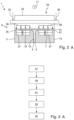
- the T-shaped semi-finished product the cross-sectional shape of which is particularly evident in the sectional view of Figure 2 can be clearly seen, comprises a web 5 and a flange 7 extending perpendicular to the web 5.
- the fabric 3 is mixed with a binding agent that can be activated by heat and, after hardening, bonds the layers of the fabric 3 together.
- the device 1 of the embodiments A and B comprises firstly a web forming tool 9 with two jaws 11, 13, between which a web section 15 of the scrim 3 is clamped. As in Figure 1 As can be seen, the jaws 11, 13 extend in a working direction 17, which Figure 2 runs perpendicularly into the drawing plane.
- the flange section 19 of the fabric 3 protruding upwards from the web forming tool 9 is divided into two parts by a forming tool 21 moved in the working direction 17 over the web forming tool 9 and formed into the flange 7 of the T-shaped semi-finished product.
- the forming tool 21 comprises a plurality of forming rollers 23, of which Figure 1 however, only one is shown in order to keep the drawing clear.
- the flange section 19 of the fabric 3, which previously extended essentially in one plane with the web section 15, is first divided into two parts, each with one or more layers, and then folded over onto contact surfaces 25, 27, which are formed by surfaces 25, 27 of the jaws 11, 13 of the web forming tool 9 facing the forming tool 21.
- a flexible magnetizable film 31 is then applied to the flange section 19, which in the case of embodiments A is formed into the flange 7, using a depositing device 29. deposited or applied.
- the depositing device 29 is attached together with the forming tool 21 to a common frame, which is not shown in the figures, and is moved together with the forming tool 21 in the working direction 17 over the web forming tool 9.
- the depositing device 29 comprises a pressure roller 33, with which the film 31 is pressed firmly against the formed flange section 19 of the scrim 3.
- the depositing device 29 exerts a force 35 on the film 31 and the underlying scrim 3, which acts perpendicular to the contact surfaces 25, 27. This ensures that the film 31 rests flat on the formed scrim 3 and follows the contours of the flange 7, even if this should have curvatures or other complex geometries.
- a magnetic force is exerted on the film 31 placed on the formed flange section 19 via permanent magnets 37 arranged in the web forming tool 9 or, more specifically, the jaws 11, 13, by which the magnetizable film 31 is subjected to a force 39 towards the contact surfaces 25, 27.
- the flange section 19 of the fabric 3 formed into the flange 7 is fixed between the contact surfaces 25, 27 and the film 31 and retains its shape. Since the film 31 is flexible and the magnetic force acts evenly on the film 31 regardless of the shape of the contact surfaces, the flange section 19 can be advantageously fixed with the film 31 even if the flange 7 is curved or follows other complex geometries.
- the device 1 also comprises a heating device 41 in the form of an infrared radiator, with which the flange section 19 can be heated through the film 31 or indirectly by heating the film 31, so that the binding agent is activated under the pressure and heat generated by the magnetic force acting on the film 31 and the layers of the scrim 3 are glued together.
- a heating device 41 in the form of an infrared radiator, with which the flange section 19 can be heated through the film 31 or indirectly by heating the film 31, so that the binding agent is activated under the pressure and heat generated by the magnetic force acting on the film 31 and the layers of the scrim 3 are glued together.
- a hose body 31 is subsequently deposited or applied to the flange section 19 formed into the flange 7 using a depositing device 29, which is moved together with the forming tool 21 in the working direction 17 over the web forming tool 9.
- the depositing device 29 comprises a pressure roller 33, with which the hose body 31 is firmly attached to the formed flange section 19 of the fabric 3.
- the depositing device 29 exerts a force 35 on the hose body 31 and the fabric 3 underneath, which acts perpendicular to the contact surfaces 25, 27. This ensures that the hose body 31 rests flat on the formed fabric 3 and follows the contours of the flange 7, even if the latter has curves or other complex geometries.
- the hose body 31 placed on the formed flange section 19 is then filled with a heated fluid, preferably gas in the form of warm air, by means of a filling device 37, the pressure of the gas in the hose body 31 being higher than atmospheric pressure.
- a heated fluid preferably gas in the form of warm air
- the hose body 31 which was previously lying flat, is pumped up and fills a cavity 39 between the flange section 19 and a holding tool 41 arranged above it.
- the holding tool 41 which comprises a plurality of holding elements 43 in the form of holding rollers 45 and is also moved in the working direction 17 over the web forming tool 9, prevents the hose body 31 from expanding too far away from the contact surfaces 25, 27.
- the pressure in the hose body 31 exerts a uniform force on the formed flange section 19, which holds the flange section 19 in position, while the warm air in the hose body 31 heats the flange section 19 and activates the binding agent. Due to the flexible shape of the hose body 31, it advantageously exerts a uniform pressure on the formed flange section 19 of the fabric 3 everywhere, even with complex web geometries, so that it can be securely fixed until the binding agent or binder has hardened and the layers of the fabric 3 have bonded together.
- the hose body 31 has a plurality of heating wires 46 in its wall 44, with which a surface 48 of the hose body 31 facing the flange section 19 after the hose body 31 has been deposited on the flange section 19 and thus also the underlying flange section 19 of the fabric 3 can be additionally heated in order to accelerate the activation and hardening of the binding agent.
- a first step 47 in the case of embodiments A, the web section 15 of the fabric 3 is first clamped between the jaws 11, 13 of the web forming tool 9 in the working direction 17.
- the layers of the fabric 3 of the flange section 19 protruding upwards from the jaws 11, 13 are divided into two parts by the forming rollers 23 of the forming tool 21 and formed onto the contact surfaces 25, 27.
- the magnetizable film 31 is placed on the formed flange section 19 using the depositing tool 29 and pressed firmly against the flange section 19 by the pressure roller 33.
- a magnetic force is generated between the magnetizable film 31 and the web forming tool 9, by means of which the film 31 is drawn onto the contact surfaces 25, 27 in such a way that pressure is exerted on the formed flange section 19 and the flange section is fixed until the binding agent is activated and hardened.
- the formed flange section 19 is heated with the heating device 41. This activates the binding agent and the layers of the flange section 19 are glued together.
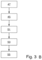
- a first step 47 in the case of embodiments B, the web section 15 of the fabric 3 is first clamped between the jaws 11, 13 of the web forming tool 9 in the working direction 17.
- the layers of the fabric 3 of the flange section 19 protruding upwards from the jaws 11, 13 are divided into two parts by the forming rollers 23 of the forming tool 21 and formed onto the contact surfaces 25, 27.
- the hose body 31 is placed on the formed flange section 19 using the depositing tool 29 and pressed firmly against the flange section 19 by the pressure roller 33.
- the holding tool 41 is positioned such that a free space 39 is formed between the holding elements 43 and the flange section 19, in which the hose body 31 runs.
- the hose body 31 is filled with warm air by the filling device 37 to a pressure that is greater than the ambient pressure, so that it fills the free space 39 and presses and fixes the flange section 19 flat against the contact surfaces 25, 27. Since the hose body 31 is heated by the warm air, the fabric 3 in the area of the formed flange section 19 also heats up. This activates the binding agent and the layers of the flange section 19 are bonded together.
Landscapes
- Engineering & Computer Science (AREA)
- Mechanical Engineering (AREA)
- Chemical & Material Sciences (AREA)
- Composite Materials (AREA)
- Moulding By Coating Moulds (AREA)
- Lining Or Joining Of Plastics Or The Like (AREA)
- Laminated Bodies (AREA)
Description
- Die vorliegende Erfindung betrifft Vorrichtungen und Verfahren zur Herstellung eines T-förmigen Halbzeugs aus einem mehrlagigen Gelege von Verstärkungsfasern für einen Verbundwerkstoff. Es werden zwei Gruppen von Ausführungsformen A und B beschrieben.
- Im Flugzeugbau werden an vielen Stellen Faserverbundwerkstoffe verwendet, aus denen besonders leichte und damit wirtschaftliche Flugzeugbauteile hergestellt werden können. Faserverbundwerkstoffe können in verschiedenen Formen verarbeitet werden. Beispielsweise werden oftmals bereits mit einem Harz getränkte Gewebe verarbeitet, die auch als Prepregs bezeichnet werden. Alternativ ist es bekannt, mehrlagige ebene Gelege aus Verstärkungsfasern zu Halbzeugen umzuformen, bevor diese mit Harz versetzt und ausgehärtet werden. Da die Gelege aus lose aufeinanderliegenden Lagen gebildet werden, bei denen die Fasern anders als bei Geweben nicht miteinander verwoben sind, bezeichnet man sie auch als "non-crimp fabric."
- Damit die Gelege nicht gegeneinander verrutschen, sind sie mit einem Bindemittel versetzt, dass - einmal aktiviert - die Fasern der unterschiedlichen Lagen miteinander verbindet. Bekannt sind beispielsweise Bindemittel, die durch Wärme aktiviert werden. Aus dem Stand der Technik ist es bekannt, das Bindemittel zu aktivieren, direkt bevor das Gelege umgeformt wird, so dass nach dem Umformen die Lagen des Geleges miteinander verbunden sind, nicht mehr gegeneinander verrutschen und ihre Form bis zum Einbringen des Harzes beibehalten. Dieses Vorgehen hat jedoch den Nachteil, dass zum Umformen nur wenig Zeit verbleibt und Fehler beim Umformen nicht oder nur schwerlich korrigiert werden können, wenn das Bindemittel einmal ausgehärtet ist.
- Alternativ ist es beispielsweise aus
DE 10 2016 125 958 A1 bekannt, ein Gelege aus einer Mehrzahl von gestapelten Faserlagen zu einem T-förmigen Halbzeug umzuformen, bevor das das Bindemittel aktiviert wird. Das T-förmige Halbzeug umfasst einen Steg und einen sich senkrecht zum Steg erstreckenden Flansch, wobei ein Stegabschnitt des Geleges, der den Steg bilden soll, in einem Stegformwerkzeug eingespannt wird, und der verbleibende Flanschabschnitt des Geleges mit Hilfe eines Umformwerkzeug mit mehreren Rollen in zwei Teile aufgeteilt und zu einem Steg umgeformt wird. - Da das Bindemittel erst nach dem Umformen aktiviert und das Gelege auch erst nach dem Umformen mit einem Harz getränkt und ausgehärtet wird, können die Lagen des Geleges leicht umgeformt werden. Damit die Faserlagen nach dem Umformen ihre Position beibehalten, bis das Bindemittel aktiviert und ausgehärtet ist, kann nach dem Umformen der Faserlagen des Geleges beispielsweise eine Folie auf dem den Flansch bildenden Teil des Geleges angeordnet werden. Die Folie oder Membran wird mittels eines Unterdrucks an das Stegformwerkzeug angesaugt und hält so das Gelege in Position. Durch zusätzliche Wärmequellen, beispielsweise Infrarotstrahler oder Induktionsspulen, kann das Bindemittel im Gelege dann aktiviert werden, so dass sich die Lagen des Geleges bereits miteinander verbinden, bevor sie mit Harz getränkt und ausgehärtet werden.
- Das Dokument
DE 102007032819A1 offenbart ein Verfahren zur Herstellung eines T-Stringers, insbesondere im Luft- und Raumfahrtbereich, mit folgenden Schritten: Bereitstellen eines ersten und zweiten Vorgelegestreifens; Auflegen einer ersten Trennfolie auf einen einem auszubildenden Stringerfuß des T-Stringers zugeordneten Abschnitt des ersten Vorgelegestreifens, wobei die erste Trennfolie an eine Kante des ersten Vorgelegestreifens angrenzt; Auflegen einer zweiten Trennfolie auf einen dem auszubildenden Stringerfuß zugeordneten Abschnitt des zweiten Vorgelegestreifens, wobei die zweite Trennfolie an eine Kante des zweiten Vorgelegestreifens angrenzt; Auflegen des zweiten Vorgelegestreifens auf den ersten Vorgelegestreifen derart, dass ein einem auszubildenden Stringersteg des T-Stringers zugeordneter Abschnitt des zweiten Vorgelegestreifens auf einem dem auszubildenden Stringersteg des T-Stringers zugeordneten Abschnitt des ersten Vorgelegestreifens aufliegt und die erste und zweite Trennfolie aufeinander aufliegen; Auffalten der dem auszubildenden Stringerfuß zugeordneten Abschnitte des ersten und zweiten Vorgelegestreifens in entgegengesetzter Richtung; und wenigstens teilweise Aushärten des ersten und zweiten Vorgelegestreifens zum Ausbilden des T-Stringers. - Vor diesem Hintergrund ist es eine Aufgabe der vorliegenden Erfindung, eine alternative Vorrichtung und ein alternatives Verfahren zur Herstellung eines T-förmigen Halbzeugs aus einem mehrlagigen Gelege anzugeben.
- Die Aufgabe wird gelöst durch eine Vorrichtung A nach Anspruch 1 und ein Verfahren A nach Anspruch 4 sowie eine Vorrichtung B nach Anspruch 6 und ein Verfahren B nach Anspruch 12.
- Bevorzugte Ausgestaltungen des Verfahrens A und B und der Vorrichtung A und B sind in den abhängigen Ansprüchen angegeben. Die Bezugszeichen beziehen sich dabei jeweils auf die
Figuren 1A ,2A, 3A für die Ausführungsformen A und auf dieFiguren 1B, 2B ,3B für die Ausführungsformen B. - Gemäß einem ersten Aspekt wird die Aufgabe durch eine Vorrichtung A zur Herstellung eines T-förmigen Halbzeugs aus einem mehrlagigen Gelege von Verstärkungsfasern für einen Verbundwerkstoff gelöst, wobei das Gelege mit einem Bindemittel versetzt ist und das T-förmige Halbzeug einen Steg und einen sich senkrecht zum Steg erstreckenden Flansch aufweist. Die Vorrichtung umfasst ein sich in einer Arbeitsrichtung erstreckendes Stegformwerkzeug, das konfiguriert ist, um einen den Steg formenden Stegabschnitt des mehrlagigen Geleges einzuspannen, ein Umformwerkzeug, das in Arbeitsrichtung über Stegformwerkzeug bewegbar ist, um Lagen eines Flanschabschnitts des mehrlagigen Geleges in zwei Teile aufzuteilen und zu dem Flansch des T-förmigen Halbzeugs umzuformen, und eine Ablagevorrichtung, die ebenfalls in Arbeitsrichtung über das Stegformwerkzeug bewegbar und konfiguriert ist, um eine flexible Folie auf dem zum Flansch umgeformten Flanschabschnitt abzulegen, wobei das Stegformwerkzeug und die flexible Folie so ausgebildet sind, dass eine magnetische Kraft zwischen der Folie und dem Stegformwerkzeug erzeugt wird, die die flexible Folie auf das Stegformwerkzeug zieht, so dass die flexible Folie den zum
- Flansch umgeformten Flanschabschnitt festhält, wobei des Stegformwerkzeug einen oder mehrere Permanentmagnete und/oder einen oder mehrere Elektromagnete aufweist und wobei die flexible Folie aus einem magnetisierbaren oder magnetischen Material gebildet ist.
- Gemäß einem ersten Aspekt wird die Aufgabe durch eine Vorrichtung B zur Herstellung eines T-förmigen Halbzeugs aus einem mehrlagigen Gelege von Verstärkungsfasern für einen Verbundwerkstoff gelöst, wobei das Gelege mit einem Bindemittel versetzt ist und das T-förmige Halbzeug einen Steg und einen sich senkrecht zum Steg erstreckenden Flansch aufweist. Die Vorrichtung umfasst ein sich in einer Arbeitsrichtung erstreckendes Stegformwerkzeug, das konfiguriert ist, um einen den Steg formenden Stegabschnitt des mehrlagigen Geleges einzuspannen, ein Umformwerkzeug, das in Arbeitsrichtung über Stegformwerkzeug bewegbar ist, um Lagen eines Flanschabschnitts des mehrlagigen Geleges in zwei Teile aufzuteilen und zu dem Flansch des T-förmigen Halbzeugs umzuformen, eine Ablagevorrichtung, die ebenfalls in Arbeitsrichtung über das Stegformwerkzeug bewegbar ist, um einen Schlauchkörper auf dem zum Flansch umgeformten Flanschabschnitt abzulegen, ein Haltewerkzeug, das ein oder mehrere Halteelemente umfasst, wobei das Haltewerkzeug so positionierbar ist, dass der Schlauchkörper in einem Freiraum zwischen dem oder den Haltelementen und dem zum Flansch umgeformten Flanschabschnitt angeordnet ist, und eine Füllvorrichtung, die konfiguriert ist, um den Schlauchkörper derart mit einem Fluid zu befüllen, dass der Schlauchkörper den Freiraum ausfüllt und den zum Flansch umgeformten Flanschabschnitt festhält.
- Mit anderen Worten betrifft die vorliegende Erfindung eine Vorrichtung, mit der Gelege aus Verstärkungsfasern, beispielsweise Glasfasern oder Kohlenstofffasern, zu einem T-förmigen Halbzeug umgeformt werden können. Das Gelege umfasst eine Vielzahl von lose aufeinanderliegenden oder übereinander gestapelten Lagen, die gegeneinander verschoben werden können. Die einzelnen Lagen des Geleges sind somit nicht miteinander verbunden. Insbesondere sind sie weder miteinander verwoben noch vernäht oder verklebt. Zwischen den Lagen ist ein beispielsweise pulverförmiges Bindemittel angeordnet, das, sobald es aktiviert und ausgehärtet ist, die Lagen miteinander verbindet oder verklebt, so dass diese nicht mehr gegeneinander verschoben werden können. Ist das Bindemittel einmal ausgehärtet, können die Lagen auch nur noch schwerlich umgeformt werden, da die Lagen des Geleges relativ zueinander fixiert sind.
- Das Gelege ist in zumindest zwei Abschnitte unterteilt, einen Stegabschnitt und einen Flanschabschnitt. Der Bereich des Geleges, der als Stegabschnitt bezeichnet wird, soll den Steg des T-förmigen Halbzeugs bilden, während aus dem als Flanschabschnitt bezeichneten Bereich des Geleges mit der Vorrichtung der Flansch des T-förmigen Halbzeugs geformt wird.
- Die Vorrichtung A selbst umfasst zumindest drei Elemente: ein Stegformwerkzeug, ein Umformwerkzeug und eine Ablagevorrichtung. Die verschiedenen Elemente können eigenständig sein, aber auch kombiniert werden. Insbesondere können das Umformwerkzeug und die Ablagevorrichtung am gleichen Rahmen angeordnet und gemeinsam bewegt werden.
- Die Vorrichtung B selbst umfasst zumindest fünf Elemente: ein Stegformwerkzeug, ein Umformwerkzeug, eine Ablagevorrichtung, ein Haltewerkzeug und eine Füllvorrichtung. Die verschiedenen Elemente können eigenständig sein, aber auch kombiniert werden.
- Das Stegformwerkzeug ist dafür vorgesehen, den Stegabschnitt des Geleges einzuspannen, also die Lagen des mehrlagigen Geleges in dem Bereich festzuhalten oder zu klemmen, der später einmal den Steg des T-förmigen Halbzeugs bilden soll. Hierzu erstreckt sich das Stegformwerkzeug entlang einer Arbeitsrichtung, die mit der Richtung zusammenfällt, in die sich der Steg des T-förmigen Halbzeugs erstrecken soll. Die Arbeitsrichtung muss nicht notwendigerweise eine Gerade sein, sondern kann auch Krümmungen aufweisen. Vorzugsweise umfasst das Stegformwerkzeug zwei langgestreckte Backen, die sich parallel zur Arbeitsrichtung erstrecken und so konfiguriert sind, dass der Stegabschnitt zwischen den langgestreckten Backen eingespannt werden kann.
- Nachdem der Stegabschnitt des Geleges im Stegformwerkzeug eingespannt worden ist, wird der aus dem Stegformwerkzeug herausragende Flanschabschnitt des mehrlagigen Geleges mit dem Umformwerkzeug zu dem Flansch des T-förmigen Halbzeugs umgeformt. Dabei teilt das in Arbeitsrichtung über das Stegformwerkzeug fahrende Umformwerkzeug die Lagen des Geleges zunächst in zwei Teile auf, die dann in entgegengesetzte Richtung relativ zum Stegabschnitt umgeklappt werden. Die Anzahl der Lagen in den beiden Teilen kann gleich groß oder unterschiedlich groß sein.
- Hierzu weist das Umformwerkzeug vorzugsweise eine Mehrzahl von Umformrollen auf, die parallel zur Arbeitsrichtung über das Stegformwerkzeug bewegbar sind, um den Flanschabschnitt des sich zunächst in einer Ebene erstreckende Geleges in zwei Teile aufzuteilen und zu dem Flansch umzuformen. Die Umformrollen drücken die Lagen des Flanschabschnitts zunächst auseinander und klappen sie dann kontinuierlich immer weiter um, bis sich der Flanschabschnitt in einer Ebene erstreckt, die senkrecht zu der Ebene verläuft, in der der von dem Stegformwerkzeug gehaltene Stegabschnitt verläuft. Dabei können beispielsweise auf das Umformwerkzeug zuweisende Oberflächen des Stegformwerkzeugs, insbesondere der langgestreckten Backen des Stegformwerkzeugs, als Anlageflächen dienen, gegen die der Flanschabschnitt umgeformt wird.
- Anschließend wird im Fall der Ausführungsformen A mit der Ablagevorrichtung eine flexible Folie oder Membran auf dem zum Flansch umgeformten Flanschabschnitt abgelegt, wobei die Folie aus einem magnetischen oder magnetisierbaren Material gebildet ist. Die Ablagevorrichtung umfasst in einer bevorzugten Ausführungsform eine Anpressrolle, die in Arbeitsrichtung derart über das Stegformwerkzeug bewegbar ist, das die flexible Folie in Arbeitsrichtung hinter dem Umformwerkzeug über die Anpressrolle auf den zum Flansch umgeformten Flanschabschnitt geführt und an den Flanschabschnitt angedrückt wird. So wird auf vorteilhafte Weise sichergestellt, dass die Folie eben auf dem umgeformten Flanschabschnitt anliegt, auch wenn der Flansch des T-förmigen Halbzeugs gekrümmt sein sollte oder anderen komplexen Geometrien folgt.
- Schließlich sind im Fall der Ausführungsformen A das Stegformwerkzeug und die flexible Folie so ausgebildet, dass zwischen Folie und Stegformwerkzeug eine magnetische Kraft erzeugt wird bzw. erzeugt werden kann, die die Folie zum Stegformwerkzeug bzw. zu von dem Stegformwerkzeug gebildeten Anlageflächen für den Flanschabschnitt hin zieht. Hierfür weist das Stegformwerkzeug einen oder mehrere Permanentmagnete und/oder einen oder mehrere Elektromagnete auf, die mit einer magnetischen oder magnetisierbaren Folie zusammenwirken.
- Durch die auf die Folie wirkende Magnetkraft wird im Fall der Ausführungsformen A der umgeformte Flanschabschnitt zwischen Folie und Stegformwerkzeug eingeklemmt und sicher in der umgeformten Position gehalten. Da die Folie flexibel ist, kann sie auch auf gekrümmten oder auf andere Weise nicht ebenen Anlageflächen abgelegt werden und die Form des Flansches unmittelbar nachvollziehen. So wird auf vorteilhafte Weise sichergestellt, dass der umgeformte Flanschabschnitt dauerhaft in seiner umgeformten Form gehalten wird, bis das Bindemittel aktiviert wurde und die Lagen des mehrlagigen Geleges miteinander verbunden wurden, so dass sie nicht mehr gegeneinander verschoben werden können. Im Gegensatz zu Vorrichtungen, bei denen die Folie mittels eines Unterdrucks an das Stegformwerkzeug angesaugt wird, hat die Verwendung von Magnetkraft den Vorteil, dass die Folie flächig über den gesamten Bereich angezogen werden kann, ohne dass hierfür ein luftdurchlässiges Gelege verwendet werden müsste.
- In einer bevorzugten Ausführungsform im Fall der Ausführungsformen A umfasst die Vorrichtung weiterhin eine Heizvorrichtung, die dazu konfiguriert ist, den zum Flansch umgeformten Flanschabschnitt zu erwärmen, so dass das Bindemittel, mit dem das Gelege versetzt ist, aktiviert wird. Mit anderen Worten wird mit der Heizvorrichtung der umgeformte Flanschabschnitt erwärmt und das Bindemittel, mit dem das Gelege versehen ist, aktiviert. Die Heizvorrichtung kann beispielsweise im Stegformwerkzeug integriert sein und durch Heizspiralen gebildet sein. Es ist aber auch denkbar, Infrarotstrahler zu verwenden, die beispielsweise die Folie oder durch die Folie hindurch den Flanschabschnitt erwärmen.
- In einem zweiten Aspekt wird im Fall der Ausführungsformen A die Aufgabe durch ein Verfahren zur Herstellung eines T-förmigen Halbzeugs aus einem mehrlagigen Gelege von Verstärkungsfasern für einen Verbundwerkstoff gelöst. Das Gelege ist mit einem Bindemittel versetzt. Das T-förmige Halbzeug weist einen Steg und einen sich senkrecht zum Steg erstreckenden Flansch auf. Das Verfahren umfasst die Schritte Einspannen eines den Steg formenden Stegabschnitts des mehrlagigen Geleges in einer Arbeitsrichtung in einem Stegwerkzeug, Aufteilen von Lagen eines Flanschabschnitts des mehrlagigen Geleges in zwei Teile und Umformen der Lagen des Flanschabschnitts zu dem Flansch des T-förmigen Halbzeugs mit einem Umformwerkzeug, das in der Arbeitsrichtung über das Stegformwerkzeug bewegt wird, Ablegen einer flexiblen Folie auf dem zum Flansch umgeformten Flanschabschnitt in Arbeitsrichtung, und Erzeugen einer magnetischen Kraft zwischen der Folie und dem Stegformwerkzeug, die die flexible Folie auf das Stegformwerkzeug zieht, so dass die flexible Folie den zum Flansch umgeformten Flanschabschnitt festhält.
- Vorzugsweise wird im Fall der Ausführungsformen A der zum Flansch umgeformte Flanschabschnitt erwärmt und das Bindemittel, mit dem das Gelege versetzt ist, aktiviert, während die magnetische Kraft erzeugt wird.
- Nachfolgend wird im Fall der Ausführungsformen B mit der Ablagevorrichtung ein Schlauchkörper mit einem vorzugsweise flachen Querschnitt auf dem zum Flansch umgeformten Flanschabschnitt angeordnet und vorzugsweise fest an diesen angedrückt. Die Breite des Schlauchkörpers parallel zu der Ebene, in der sich der Flanschabschnitt nach dem Umformen erstreckt, sollte dabei vorzugsweise zumindest der Breite des Flanschabschnitts entsprechen. Die Ablagevorrichtung fährt dabei beispielsweise direkt hinter dem Umformwerkzeug über das Stegformwerkzeug und kann insbesondere direkt mit diesem verbunden sein, indem die Ablagevorrichtung beispielsweise an dem gleichen Rahmen befestigt ist. Der Schlauchkörper ist beispielsweise aus einem flexiblen Material geformt, das auch dehnbar sein kann, aber nicht dehnbar sein muss.
- Die Ablagevorrichtung der Ausführungsformen B umfasst in einer bevorzugten Ausführungsform eine Anpressrolle, die in Arbeitsrichtung derart über das Stegformwerkzeug bewegbar ist, das der Schlauchkörper in Arbeitsrichtung hinter dem Umformwerkzeug über die Anpressrolle auf den zum Flansch umgeformten Flanschabschnitt geführt und an den Flanschabschnitt angedrückt wird. So wird sichergestellt, dass der Schlauchkörper flach auf dem umgeformten Schlauchabschnitt aufliegt und der Kontur des Flansches folgt. Zudem verhindert das Andrücken mit der Anpressrolle, dass der Schlauch bzw. der Schlauchkörper in Abschnitten mit Gas gefüllt wird, die noch nicht auf dem Flanschabschnitt angeordnet wurden, was das Ablegen des Schlauches erschweren würde.
- Oberhalb des Schlauchkörpers der Ausführungsformen B wird das Haltewerkzeug so angeordnet, dass zwischen dem umgeformten Flanschabschnitt und dem oder den Haltelementen des Haltewerkzeugs ein Freiraum oder Hohlraum verbleibt, in dem der Schlauchkörper angeordnet ist und den der Schlauchkörper ausfüllt, sobald er mit dem Fluig gefüllt ist. Vorzugsweise umfasst das Haltewerkzeug eine Mehrzahl von Haltelementen in Form von Halterollen, die in Arbeitsrichtung über das Stegformwerkzeug bewegbar sind. Die Halterollen können dabei auf gleichbleibender Höhe bewegt werden, so dass sich der Abstand zwischen den Halterollen und dem umgeformten Flanschabschnitt verändert, wenn der Flanschabschnitt in Arbeitsrichtung gekrümmt sein sollte.
- Schließlich umfasst die Vorrichtung der Ausführungsformen B eine Füllvorrichtung, beispielsweise ein Kompressor oder eine Pumpe, mit der der Schlauchkörper mit einem Fluid, bei dem es sich beispielsweise um ein Gas wie vorzugsweise Luft oder eine Flüssigkeit wie beispielsweise ein Öl handelt, befüllt werden kann. Dabei wird der Schlauchkörper mit einem Druck beaufschlagt, der größer als der Umgebungs- bzw. Atmosphärendruck ist. Der Schlauchkörper wird so weit gefüllt, dass er zumindest den Hohlraum zwischen Haltewerkzeug und umgeformten Flanschabschnitt ausfüllt. Da das Haltewerkzeug die Ausdehnung des Schlauchkörpers weg von dem Flanschabschnitt begrenzt, wird durch den Druck im Schlauchkörper eine Kraft auf den Flanschabschnitt ausgeübt, die die umgeformten Lagen in Position hält, bis das Bindemittel aktiviert und ausgehärtet ist. Da der Schlauchkörper flexibel ist, folgt er auf vorteilhafte Weise den Konturen des Flanschabschnitts, so dass auch T-förmige Halbzeuge mit komplexen Verläufen gefertigt werden können, ohne dass es hierfür zum Halten des Flanschabschnitts bis zum Aushärten des Binders aufwendiger Werkzeuge bedürfte.
- Vorzugsweise ist die Füllvorrichtung der Ausführungsformen B dazu ausgebildet ist, den Schlauchkörper mit einem erwärmten Fluid zu befüllen, so dass der Schlauchkörper den zum Flansch umgeformten Flanschabschnitt erwärmt und das Bindemittel, mit dem das Gelege versetzt ist, unter dem zusätzlich wirkenden Druck des über Atmosphärendruck gefüllten Schlauchkörpers aktiviert wird. Damit werden auf vorteilhafte Weise keine Heizelemente benötigt, um das Bindemittel zu aktivieren. Insbesondere müssen die Heizelemente weder in die Anlageflächen integriert sein, auf die der Flanschabschnitt umgeformt wird, was die Kosten für die Herstellung des entsprechenden Werkzeugs deutlich verringern sollte, noch muss der Schlauchkörper so ausgestaltet sein, dass die Wärme durch den Schlauchkörper hindurch in den Flanschabschnitt eingebracht werden kann.
- Alternativ oder zusätzlich kann der Schlauchkörper der Ausführungsformen B so ausgebildet sein, dass eine nach dem Ablegen des Schlauchkörpers auf dem umgeformten Flanschabschnitt zuweisende Oberfläche des Schlauchkörpers beheizt werden kann. Hierzu können beispielsweise Heizdrähte in der Wandung des Schlauchkörpers eingebettet sein, so dass der Schlauchkörper elektrisch beheizt werden kann.
- In einem zweiten Aspekt der Ausführungsformen B wird die Aufgabe durch ein Verfahren zur Herstellung eines T-förmigen Halbzeugs aus einem mehrlagigen Gelege von Verstärkungsfasern für einen Verbundwerkstoff gelöst. Das Gelege ist mit einem Bindemittel versetzt. Das T-förmige Halbzeug weist einen Steg und einen sich senkrecht zum Steg erstreckenden Flansch auf. Das Verfahren umfasst die Schritte Einspannen eines den Steg formenden Stegabschnitts des mehrlagigen Geleges in einer Arbeitsrichtung, Aufteilen von Lagen eines Flanschabschnitts des mehrlagigen Geleges in zwei Teile und Umformen der Lagen des Flanschabschnitts zu dem Flansch des T-förmigen Halbzeugs mit einem Umformwerkzeug, das in der Arbeitsrichtung bewegt wird, Ablegen des Schlauchkörpers auf dem zum Flansch umgeformten Flanschabschnitt in Arbeitsrichtung, Positionieren eines Haltewerkzeugs derart, dass der Schlauchkörper in einem Freiraum zwischen dem Haltewerkzeug und dem zum Flansch umgeformten Flanschabschnitt angeordnet ist, und Befüllen des Schlauchkörpers mit einem Gas, so dass der Schlauchkörper den Freiraum ausfüllt und den zum Flansch umgeformten Flanschabschnitt festhält. Beispielsweise kann eine der vorstehend beschriebenen Vorrichtungen zur Durchführung des Verfahrens oder einer der nachfolgend näher beschriebenen Ausführungsformen des Verfahrens verwendet werden.
- Vorzugsweise wird der Schlauchkörper der Ausführungsformen B mit einem erwärmten Gas befüllt, so dass der Schlauchkörper den zum Flansch umgeformten Flanschabschnitt erwärmt und das Bindemittel, mit dem das Gelege versetzt ist, aktiviert.
- Es ist im Fall der Ausführungsformen A und B weiter bevorzugt, wenn der Stegabschnitt zwischen zwei langgestreckten, sich in der Arbeitsrichtung erstreckenden Backen eines Stegformwerkzeugs eingespannt wird.
- Der Flanschabschnitt wird im Fall der Ausführungsformen A und B vorzugsweise mit einem Umformwerkzeug, das eine Mehrzahl von Umformrollen aufweist, die parallel zur Arbeitsrichtung bewegbar sind, in zwei Teile aufgeteilt und zu dem Flansch umgeformt.
- Die flexible Folie wird im Fall der Ausführungsformen A in einer bevorzugten Ausführungsform über eine Anpressrolle in Arbeitsrichtung hinter dem Umformwerkzeug auf den zum Flansch umgeformten Flanschabschnitt geführt und mit der Anpressrolle an den Flanschabschnitt angedrückt.
- In einer bevorzugten Ausführungsform der Ausführungsformen B wird der Schlauchkörper über eine Anpressrolle in Arbeitsrichtung hinter dem Umformwerkzeug auf den zum Flansch umgeformten Flanschabschnitt geführt und mit der Anpressrolle an den Flanschabschnitt angedrückt.
- Schließlich ist es im Fall der Ausführungsformen B bevorzugt, dass das Haltewerkzeug eine Mehrzahl von Haltelementen in Form von Halterollen umfasst, die in Arbeitsrichtung über den zum Flansch umgeformten Flanschabschnitt bewegt werden.
- Die Vorteile der verschiedenen Ausführungsformen des Verfahrens der Ausführungsformen A und B entsprechen den Vorteilen der verschiedenen Ausführungsformen der Vorrichtung zur Herstellung eines T-förmigen Halbzeugs.
- Nachfolgend wird die Erfindung bezugnehmend auf die Zeichnung näher beschrieben. Darin zeigen im Fall der Ausführungsformen A und B
- Figur 1
- eine seitliche Ansicht eines Ausführungsbeispiels einer Vorrichtung zur Herstellung eines T-förmigen Halbzeugs,
- Figur 2
- einen Schnitt entlang der Linie A-A durch die Vorrichtung aus
Figur 1 und - Figur 3
- ein Schritte eines Ausführungsbeispiels eines Verfahrens zur Herstellung eines T-förmigen Halbzeugs zeigendes Flussdiagramm.
- Nachfolgend wird bezugnehmend auf die
Figuren 1A und2A sowie 1B und 2B zunächst ein Ausführungsbeispiel einer Vorrichtung 1 zur Herstellung eines T-förmigen Halbzeugs für einen Faserverbundwerkstoff aus einem mehrlagigen Gelege 3 beschrieben. In den Figuren sind die einzelnen Lagen des Geleges nicht dargestellt. Das T-förmige Halbzeug, dessen Querschnittsform insbesondere in der Schnittansicht vonFigur 2 deutlich zu erkennen ist, umfasst einen Steg 5 sowie einen sich senkrecht zum Steg 5 erstreckenden Flansch 7. Das Gelege 3 ist mit einem Bindemittel versetzt, dass durch Wärme aktiviert werden kann und nach dem Aushärten die Lagen des Geleges 3 miteinander verklebt. - Die Vorrichtung 1 der Ausführungsformen A und B umfasst zunächst ein Stegformwerkzeug 9 mit zwei Backen 11, 13, zwischen denen ein Stegabschnitt 15 des Geleges 3 eingespannt wird. Wie in
Figur 1 zu erkennen ist, erstrecken sich die Backen 11, 13 in einer Arbeitsrichtung 17, die inFigur 2 senkrecht in die Zeichnungsebene hinein verläuft. - Der nach oben aus dem Stegformwerkzeug 9 herausragende Flanschabschnitt 19 des Geleges 3 wird im Fall der Ausführungsformen A und B von einem in Arbeitsrichtung 17 über das Stegformwerkzeug 9 bewegten Umformwerkzeug 21 in zwei Teile geteilt und zum Flansch 7 des T-förmigen Halbzeugs umgeformt. Das Umformwerkzeug 21 umfasst eine Vielzahl von Umformrollen 23, von denen in
Figur 1 jedoch nur eine dargestellt ist, um die Zeichnung übersichtlich zu halten. Mit den Umformrollen 23 wird der sich zuvor im Wesentlichen in einer Ebene mit dem Stegabschnitt 15 erstreckende Flanschabschnitt 19 des Geleges 3 zunächst in zwei Teile mit jeweils einer oder mehreren Lagen aufgeteilt und dann auf Anlagenflächen 25, 27 hin umgeklappt, die von auf das Umformwerkzeug 21 zuweisenden Oberflächen 25, 27 der Backen 11, 13 des Stegformwerkzeugs 9 gebildet werden. - Auf den im Fall der Ausführungsformen A zum Flansch 7 umgeformten Flanschabschnitt 19 wird nachfolgend mit einer Ablagevorrichtung 29 eine flexible magnetisierbare Folie 31 abgelegt bzw. aufgebracht. Die Ablagevorrichtung 29 ist zusammen mit dem Umformwerkzeug 21 an einem gemeinsamen Rahmen befestigt, der in den Figuren nicht dargestellt ist, und wird zusammen mit dem Umformwerkzeug 21 in Arbeitsrichtung 17 über das Stegformwerkzeug 9 bewegt. Zum Ablegen der Folie 31 umfasst die Ablagevorrichtung 29 eine Anpressrolle 33, mit der der die Folie 31 fest an den umgeformten Flanschabschnitt 19 des Geleges 3 angedrückt wird. Dabei übt die Ablagevorrichtung 29 eine Kraft 35 auf die Folie 31 sowie das darunterliegende Gelege 3 aus, die senkrecht zu den Anlagenflächen 25, 27 wirkt. Damit wird sichergestellt, dass die Folie 31 flächig auf dem umgeformten Gelege 3 aufliegt und den Konturen des Flansches 7 folgt, auch wenn dieser Krümmungen oder andere komplexe Geometrien aufweisen sollte.
- Auf die im Fall der Ausführungsformen A auf dem umgeformten Flanschabschnitt 19 abgelegte Folie 31 wird über im Stegformwerkzeug 9 bzw. konkret den Backen 11, 13 angeordnete Permanentmagnete 37 eine Magnetkraft ausgeübt, durch die die magnetisierbare Folie 31 auf die Anlageflächen 25, 27 zu mit einer Kraft 39 beaufschlagt wird. Hierdurch wird der zum Flansch 7 umgeformte Flanschabschnitt 19 des Geleges 3 zwischen den Anlageflächen 25, 27 und der Folie 31 fixiert und behält seine Form bei. Da die Folie 31 flexibel ist und die Magnetkraft unabhängig von der Form der Anlagenflächen gleichmäßig auf die Folie 31 wirkt, kann mit der Folie 31 auf vorteilhafte Weise der Flanschabschnitt 19 auch dann fixiert werden, wenn der Flansch 7 gekrümmt ist oder anderen komplexen Geometrien folgt.
- Schließlich umfasst die Vorrichtung 1 im Fall der Ausführungsformen A noch eine Heizvorrichtung 41 in Form eines Infrarotstrahlers, mit dem der Flanschabschnitt 19 durch die Folie 31 hindurch bzw. indirekt durch Erwärmen der Folie 31 aufgeheizt werden kann, so dass unter dem durch die auf die Folie 31 wirkende Magnetkraft erzeugten Druck und der Wärme das Bindemittel aktiviert wird und die Lagen des Geleges 3 miteinander verklebt werden. Durch die Fixierung des umgeformten Flanschabschnitts 19 mit der auf die Folie 31 wirkenden Magnetkraft können die Lagen des Geleges 3 so lange gehalten werden, bis das Bindemittel ausgehärtet ist.
- Auf den zum Flansch 7 umgeformten Flanschabschnitt 19 wird im Fall der Ausführungsformen B nachfolgend mit einer Ablagevorrichtung 29 ein Schlauchkörper 31 abgelegt bzw. aufgebracht, die zusammen mit dem Umformwerkzeug 21 in Arbeitsrichtung 17 über das Stegformwerkzeug 9 bewegt wird. Zum Ablegen des Schlauchkörpers 31 umfasst die Ablagevorrichtung 29 eine Anpressrolle 33, mit der der Schlauchkörper 31 fest an den umgeformten Flanschabschnitt 19 des Geleges 3 angedrückt wird. Dabei übt die Ablagevorrichtung 29 eine Kraft 35 auf den Schlauchkörper 31 sowie das darunterliegende Gelege 3 aus, die senkrecht zu den Anlagenflächen 25, 27 wirkt. Damit wird sichergestellt, dass der Schlauchkörper 31 flächig auf dem umgeformten Gelege 3 aufliegt und den Konturen des Flansches 7 folgt, auch wenn dieser Krümmungen oder andere komplexe Geometrien aufweisen sollte.
- Der auf dem umgeformten Flanschabschnitt 19 abgelegte Schlauchkörper 31 wird im Fall der Ausführungsformen B sodann mittels einer Füllvorrichtung 37 mit einem erwärmten Fluid und zwar vorzugsweise Gas in Form von warmer Luft befüllt, wobei der Druck des Gases im Schlauchkörper 31 höher als der Atmosphärendruck ist. Dadurch wird der zuvor flach liegende Schlauchkörper 31 aufgepumpt und füllt einen Hohlraum 39 zwischen dem Flanschabschnitt 19 und einem darüber angeordneten Haltewerkzeug 41 aus. Das Haltewerkzeug 41, das eine Vielzahl von Haltelementen 43 in Form von Halterollen 45 umfasst und ebenfalls in Arbeitsrichtung 17, über das Stegformwerkzeug 9 bewegt wird, verhindert, dass sich der Schlauchkörper 31 zu weit von den Anlagenflächen 25, 27 weg ausdehnen kann. Daher wird durch den Druck im Schlauchkörper 31 eine gleichmäßige Kraft auf den umgeformten Flanschabschnitt 19 ausgeübt, die den Flanschabschnitt 19 in Position hält, während die warme Luft im Schlauchkörper 31 den Flanschabschnitt 19 erwärmt und das Bindemittel aktiviert. Aufgrund der flexiblen Form des Schlauchkörpers 31 übt dieser auf vorteilhafte Weise auch bei komplexen Geometrien des Stegs überall einen gleichmäßigen Druck auf den umgeformten Flanschabschnitt 19 des Geleges 3 aus, so dass dieses sicher fixiert werden kann, bis das Bindemittel bzw. der Binder ausgehärtet und die Lagen des Geleges 3 miteinander verklebt sind.
- Zusätzlich weist im Fall der Ausführungsformen B der Schlauchkörper 31 in seiner Wandung 44 eine Mehrzahl von Heizdrähten 46 auf, mit denen einen nach Ablage des Schlauchkörpers 31 auf dem Flanschabschnitt 19 zuweisende Oberfläche 48 des Schlauchkörpers 31 und damit auch der darunterliegende Flanschabschnitt 19 des Geleges 3 zusätzlich erwärmt werden kann, um die Aktivierung und das Aushärten des Bindemittels zu beschleunigen.
- Schließlich wird im Fall der Ausführungsformen A und B bezugnehmend auf
Figur 3 ein Verfahren zur Herstellung eines T-förmigen Halbzeugs aus einem Gelege 3 beschrieben, wobei zur Durchführung des Verfahrens die in denFiguren 1 und2 gezeigte Vorrichtung 1 verwendet wird. - In einem ersten Schritt 47 wird im Fall der Ausführungsformen A zunächst der Stegabschnitt 15 des Geleges 3 zwischen den Backen 11, 13 des Stegformwerkzeugs 9 in Arbeitsrichtung 17 eingespannt. Im zweiten Schritt 49 werden die Lagen des Geleges 3 des aus den Backen 11, 13 nach oben herausstehenden Flanschabschnitts 19 durch die Umformrollen 23 des Umformwerkzeugs 21 in zwei Teile aufgeteilt und auf die Anlagenflächen 25, 27 umgeformt. Im dritten Schritt 51 wird mit dem Ablagewerkzeug 29 die magnetisierbare Folie 31 auf dem umgeformten Flanschabschnitt 19 abgelegt und durch die Anpressrolle 33 fest gegen den Flanschabschnitt 19 gedrückt. Nach dem Ablegen wird entweder unmittelbar durch Permanentmagnete 37 oder nach der Aktivierung von Elektromagneten, die anstelle oder zusätzlichen zu den Permanentmagneten 37 in der Vorrichtung 1 verwendet werden können, in einem vierten Schritt 53 eine magnetische Kraft zwischen der magnetisierbaren Folie 31 und dem Stegformwerkzeug 9 erzeugt, durch die die Folie 31 so auf die Anlagenflächen 25, 27 gezogen wird, dass auf den umgeformten Flanschabschnitt 19 ein Druck ausgeübt wird und der Flanschabschnitt bis zur Aktivierung und Aushärtung des Bindemittels fixiert wird. Schließlich wird in einem fünften Schritt 55 der umgeformte Flanschabschnitt 19 mit der Heizvorrichtung 41 erwärmt. Dadurch wird das Bindemittel aktiviert und die Lagen des Flanschabschnitts 19 miteinander verklebt.
- In einem ersten Schritt 47 wird im Fall der Ausführungsformen B zunächst der Stegabschnitt 15 des Geleges 3 zwischen den Backen 11, 13 des Stegformwerkzeugs 9 in Arbeitsrichtung 17 eingespannt. Im zweiten Schritt 49 werden die Lagen des Geleges 3 des aus den Backen 11, 13 nach oben herausstehenden Flanschabschnitts 19 durch die Umformrollen 23 des Umformwerkzeugs 21 in zwei Teile aufgeteilt und auf die Anlagenflächen 25, 27 umgeformt. Im dritten Schritt 51 wird mit dem Ablagewerkzeug 29 der Schlauchkörper 31 auf dem umgeformten Flanschabschnitt 19 abgelegt und durch die Anpressrolle 33 fest gegen den Flanschabschnitt 19 gedrückt. Nachfolgend wird im vierten Schritt 53 das Haltewerkzeug 41 so positioniert, dass ein Freiraum 39 zwischen den Haltelementen 43 und dem Flanschabschnitt 19 gebildet wird, in dem der Schlaukörper 31 verläuft. Schließlich wird in einem fünften Schritt 55 der Schlauchkörper 31 durch die Füllvorrichtung 37 mit warmer Luft auf einen Druck befüllt, der größer als der Umgebungsdruck ist, so dass er den Freiraum 39 ausfüllt und den Flanschabschnitt 19 flächig an die Anlageflächen 25, 27 drückt und fixiert. Da der Schlauchkörper 31 durch die warme Luft erwärmt wird, erwärmt sich auch das Gelege 3 in Bereich des umgeformten Flanschabschnitts 19. Dadurch wird das Bindemittel aktiviert und die Lagen des Flanschabschnitts 19 miteinander verklebt.
- Die Schritte des Verfahrens können im Fall der Ausführungsformen A und B parallel ausgeführt werden.
Claims (15)
- Vorrichtung (1) zur Herstellung eines T-förmigen Halbzeugs aus einem mehrlagigen Gelege (3) von Verstärkungsfasern für einen Verbundwerkstoff, wobei das Gelege (3) mit einem Bindemittel versetzt ist und das T-förmige Halbzeug einen Steg (5) und einen sich senkrecht zum Steg (5) erstreckenden Flansch (7) aufweist, die Vorrichtung (1) umfassendein sich in einer Arbeitsrichtung (17) erstreckendes Stegformwerkzeug (9), das konfiguriert ist, um einen den Steg (5) formenden Stegabschnitt (15) des mehrlagigen Geleges (3) einzuspannen,ein Umformwerkzeug (21), das in Arbeitsrichtung (17) über Stegformwerkzeug (9) bewegbar ist, um Lagen eines Flanschabschnitts (19) des mehrlagigen Geleges in zwei Teile aufzuteilen und zu dem Flansch (7) des T-förmigen Halbzeugs umzuformen, dadurch gekennzeichnet, dass die Vorrichtung weiter umfasst:eine Ablagevorrichtung (29), die ebenfalls in Arbeitsrichtung (17) über das Stegformwerkzeug (9) bewegbar und konfiguriert ist, um eine flexible Folie (31) auf dem zum Flansch (7) umgeformten Flanschabschnitt (19) abzulegen, wobei das Stegformwerkzeug (9) und die flexible Folie (31) so ausgebildet sind, dass eine magnetische Kraft zwischen der Folie (31) und dem Stegformwerkzeug (9) erzeugt wird, die die flexible Folie (31) auf das Stegformwerkzeug (9) zieht, so dass die flexible Folie (31) den zum Flansch (7) umgeformten Flanschabschnitt (19) festhält,wobei das Stegformwerkzeug (q) einen oder mehrere Permanentmagnete (37) und/oder einen oder mehrere Elektromagnete aufweist undwobei die flexible Folie (31) aus einem magnetisierbaren oder magnetischen Material gebildet ist.
- Vorrichtung (1) nach Anspruch 1, wobei das Umformwerkzeug (21) eine Mehrzahl von Umformrollen (23) aufweist, die parallel zur Arbeitsrichtung (17) über das Stegformwerkzeug (9) bewegbar sind, um den Flanschabschnitt (19) des sich zunächst in einer Ebene erstreckende Geleges (3) in zwei Teile aufzuteilen und zu dem Flansch (7) umzuformen.
- Vorrichtung (1) nach einem der vorhergehenden Ansprüche, wobei die Ablagevorrichtung (29) eine Anpressrolle (33) umfasst, die in Arbeitsrichtung (17) derart über das Stegformwerkzeug (9) bewegbar ist, dass die flexible Folie (31) in Arbeitsrichtung (17) hinter dem Umformwerkzeug (21) über die Anpressrolle (33) auf den zum Flansch (7) umgeformten Flanschabschnitt (19) geführt und an den Flanschabschnitt (19) angedrückt wird.
- Verfahren (1) zur Herstellung eines T-förmigen Halbzeugs aus einem mehrlagigen Gelege (3) von Verstärkungsfasern für einen Verbundwerkstoff, wobei das Gelege (3) mit einem Bindemittel versetzt ist und das T-förmige Halbzeug einen Steg (5) und einen sich senkrecht zum Steg (5) erstreckenden Flansch (7) aufweist, wobei das Verfahren die folgenden Schritte umfasst:Einspannen eines den Steg (5) formenden Stegabschnitts (15) des mehrlagigen Geleges (3) in einer Arbeitsrichtung (17) in einem Stegformwerkzeug (9),Aufteilen von Lagen eines Flanschabschnitts (19) des mehrlagigen Geleges (3) in zwei Teile und Umformen der Lagen des Flanschabschnitts (19) zu dem Flansch (7) des T-förmigen Halbzeugs mit einem Umformwerkzeug (21), das in der Arbeitsrichtung (17) über das Stegformwerkzeug (9) bewegt wird,Ablegen einer flexiblen Folie (31) auf dem zum Flansch (7) umgeformten Flanschabschnitt (19) in Arbeitsrichtung (17),Erzeugen einer magnetischen Kraft zwischen der Folie (31) und dem Stegformwerkzeug (9), die die flexible Folie (31) auf das Stegformwerkzeug (9) zieht, so dass die flexible Folie (31) den zum Flansch (7) umgeformten Flanschabschnitt (19) festhält.
- Verfahren nach Anspruch 4, wobei die flexible Folie (31) über eine Anpressrolle (33) in Arbeitsrichtung (17) hinter dem Umformwerkzeug (21) auf den zum Flansch (7) umgeformten Flanschabschnitt (19) geführt und mit der Anpressrolle (33) an den Flanschabschnitt (19) angedrückt wird.
- Vorrichtung (1) zur Herstellung eines T-förmigen Halbzeugs aus einem mehrlagigen Gelege (3) von Verstärkungsfasern für einen Verbundwerkstoff, wobei das Gelege (3) mit einem Bindemittel versetzt ist und das T-förmige Halbzeug einen Steg (5) und einen sich senkrecht zum Steg (5) erstreckenden Flansch (7) aufweist, die Vorrichtung (1) umfassendein sich in einer Arbeitsrichtung (17) erstreckendes Stegformwerkzeug (9), das konfiguriert ist, um einen den Steg (5) formenden Stegabschnitt (15) des mehrlagigen Geleges (3) einzuspannen,ein Umformwerkzeug (21), das in Arbeitsrichtung (17) über Stegformwerkzeug (9) bewegbar ist, um Lagen eines Flanschabschnitts (19) des mehrlagigen Geleges (3) in zwei Teile aufzuteilen und zu dem Flansch (7) des T-förmigen Halbzeugs umzuformen,eine Ablagevorrichtung (29), die ebenfalls in Arbeitsrichtung (17) über das Stegformwerkzeug (9) bewegbar ist, um einen Schlauchkörper (31) auf dem zum Flansch (7) umgeformten Flanschabschnitt (19) abzulegen,ein Haltewerkzeug (41), das ein oder mehrere Halteelemente (43) umfasst, wobei das Haltewerkzeug (41) so positionierbar ist, dass der Schlauchkörper (31) in einem Freiraum (39) zwischen dem oder den Haltelementen (43) und dem zum Flansch (7) umgeformten Flanschabschnitt (19) angeordnet ist, undeine Füllvorrichtung (37), die konfiguriert ist, um den Schlauchkörper (31) derart mit einem Fluid zu befüllen, dass der Schlauchkörper (31) den Freiraum (39) ausfüllt und den zum Flansch (7) umgeformten Flanschabschnitt (19) festhält.
- Vorrichtung (1) nach Anspruch 6, wobei die Füllvorrichtung (37) dazu ausgebildet ist, den Schlauchkörper (31) mit einem erwärmten Fluid zu befüllen, so dass der Schlauchkörper (31) den zum Flansch (7) umgeformten Flanschabschnitt (19) erwärmt und das Bindemittel, mit dem das Gelege (3) versetzt ist, aktiviert wird.
- Vorrichtung (1) nach einem der Ansprüche 6 bis 7, wobei das Umformwerkzeug (21) eine Mehrzahl von Umformrollen (23) aufweist, die parallel zur Arbeitsrichtung (17) über das Stegformwerkzeug (9) bewegbar sind, um den Flanschabschnitt (19) des sich zunächst in einer Ebene erstreckende Geleges (3) in zwei Teile aufzuteilen und zu dem Flansch (7) umzuformen.
- Vorrichtung (1) nach einem der Ansprüche 6 bis 8, wobei die Ablagevorrichtung (29) eine Anpressrolle (33) umfasst, die in Arbeitsrichtung (17) derart über das Stegformwerkzeug (9) bewegbar ist, das der Schlauchkörper (31) in Arbeitsrichtung (29) hinter dem Umformwerkzeug (21) über die Anpressrolle (33) auf den zum Flansch (7) umgeformten Flanschabschnitt (19) geführt und an den Flanschabschnitt (19) angedrückt wird.
- Vorrichtung (1) nach einem der Ansprüche 6 bis 9, wobei das Haltewerkzeug (41) eine Mehrzahl von Haltelementen (43) in Form von Halterollen (45) umfasst, die in Arbeitsrichtung (17) über das Stegformwerkzeug (9) bewegbar sind.
- Vorrichtung nach einem der vorhergehenden Ansprüche 6 bis 10, wobei der Schlauchkörper (31) so ausgebildet ist, dass eine nach dem Ablegen des Schlauchkörpers (31) auf dem umgeformten Flanschabschnitt (19) zuweisende Oberfläche (48) des Schlauchkörpers (31) elektrisch beheizt werden kann.
- Verfahren zur Herstellung eines T-förmigen Halbzeugs aus einem mehrlagigen Gelege (3) von Verstärkungsfasern für einen Verbundwerkstoff, wobei das Gelege (3) mit einem Bindemittel versetzt ist und das T-förmige Halbzeug einen Steg (5) und einen sich senkrecht zum Steg (5) erstreckenden Flansch (7) aufweist, wobei das Verfahren die folgenden Schritte umfasst:Einspannen eines den Steg (5) formenden Stegabschnitts (15) des mehrlagigen Geleges (3) in einer Arbeitsrichtung (17),Aufteilen von Lagen eines Flanschabschnitts (19) des mehrlagigen Geleges (3) in zwei Teile und Umformen der Lagen des Flanschabschnitts (19) zu dem Flansch (7) des T-förmigen Halbzeugs mit einem Umformwerkzeug (21), das in Arbeitsrichtung (17) bewegt wird,Ablegen des Schlauchkörpers (31) auf dem zum Flansch (7) umgeformten Flanschabschnitt (19) in Arbeitsrichtung (17),Positionieren eines Haltewerkzeugs (41) derart, dass der Schlauchkörper (31) in einem Freiraum (39) zwischen dem Haltewerkzeug (41) und dem zum Flansch (7) umgeformten Flanschabschnitt (19) angeordnet ist, undBefüllen des Schlauchkörpers (31) mit einem Fluid, so dass der Schlauchkörper (31) den Freiraum (39) ausfüllt und den zum Flansch (7) umgeformten Flanschabschnitt (19) festhält.
- Verfahren nach Anspruch 12, wobei der Flanschabschnitt (19) mit einem Umformwerkzeug (21), das eine Mehrzahl von Umformrollen (23) aufweist, die parallel zur Arbeitsrichtung (17) bewegt werden, in zwei Teile aufgeteilt und zu dem Flansch (7) umgeformt wird.
- Verfahren nach einem der Ansprüche 12 bis 13, wobei der Schlauchkörper (31) über eine Anpressrolle (33) in Arbeitsrichtung (17) hinter dem Umformwerkzeug (21) auf den zum Flansch (7) umgeformten Flanschabschnitt (19) geführt und mit der Anpressrolle (33) an den Flanschabschnitt (19) angedrückt wird.
- Verfahren nach einem der Ansprüche 12 bis 14, wobei das Haltewerkzeug (41) eine Mehrzahl von Haltelementen (43) in Form von Halterollen (45) umfasst, die in Arbeitsrichtung (17) über den zum Flansch (7) umgeformten Flanschabschnitt (19) bewegt werden.
Applications Claiming Priority (3)
| Application Number | Priority Date | Filing Date | Title |
|---|---|---|---|
| DE102019125494.9A DE102019125494A1 (de) | 2019-09-23 | 2019-09-23 | Vorrichtung und Verfahren zur Herstellung eines T-förmigen Halbzeugs aus einem mehrlagigen Gelege |
| DE102019125498.1A DE102019125498A1 (de) | 2019-09-23 | 2019-09-23 | Vorrichtung und Verfahren zur Herstellung eines T-förmigen Halbzeugs aus einem mehrlagigen Gelege von Verstärkungsfasern |
| PCT/EP2020/075866 WO2021058350A1 (de) | 2019-09-23 | 2020-09-16 | Vorrichtungen und verfahren zur herstellung eines t-förmigen halbzeugs aus einem mehrlagigen gelege |
Publications (2)
| Publication Number | Publication Date |
|---|---|
| EP4034359A1 EP4034359A1 (de) | 2022-08-03 |
| EP4034359B1 true EP4034359B1 (de) | 2024-04-10 |
Family
ID=72521644
Family Applications (1)
| Application Number | Title | Priority Date | Filing Date |
|---|---|---|---|
| EP20772301.6A Active EP4034359B1 (de) | 2019-09-23 | 2020-09-16 | Vorrichtungen und verfahren zur herstellung eines t-förmigen halbzeugs aus einem mehrlagigen gelege |
Country Status (4)
| Country | Link |
|---|---|
| US (2) | US12023829B2 (de) |
| EP (1) | EP4034359B1 (de) |
| CN (1) | CN114051447A (de) |
| WO (1) | WO2021058350A1 (de) |
Family Cites Families (35)
| Publication number | Priority date | Publication date | Assignee | Title |
|---|---|---|---|---|
| US2401299A (en) * | 1942-10-03 | 1946-06-04 | Universal Moulded Products Cor | Molding and gluing press |
| US2975476A (en) * | 1959-03-02 | 1961-03-21 | John E Burke | Press |
| US4836765A (en) * | 1987-12-03 | 1989-06-06 | United Technologies Corporation | Molding apparatus for composite materials |
| FR2693146B1 (fr) * | 1992-07-02 | 1994-08-19 | Snecma | Installation pour la fabrication par drapage de structures multicouches en matériaux composites. |
| US5538589A (en) * | 1994-08-31 | 1996-07-23 | The Boeing Company | Composite stringer assembly machine |
| US5665301A (en) * | 1995-07-11 | 1997-09-09 | Arctek Inc. | Apparatus and method for forming fiber reinforced composite articles |
| US5820894A (en) * | 1995-10-06 | 1998-10-13 | Mcdonnell Douglas Corporation | Method and apparatus for consolidating a workpiece at elevated temperature |
| EP1126966B1 (de) * | 1998-10-23 | 2003-11-19 | Airbus UK Limited | Walzformgebungs-machine und walzformgebungs-verfahren |
| US6896841B2 (en) * | 2003-03-20 | 2005-05-24 | The Boeing Company | Molding process and apparatus for producing unified composite structures |
| JP3782072B2 (ja) * | 2003-05-30 | 2006-06-07 | 川崎重工業株式会社 | 複合材型材の成形方法及び装置 |
| US7249943B2 (en) * | 2003-08-01 | 2007-07-31 | Alliant Techsystems Inc. | Apparatus for forming composite stiffeners and reinforcing structures |
| DE102004006615B4 (de) * | 2004-02-10 | 2016-03-31 | Airbus Helicopters Deutschland GmbH | Verfahren zur Herstellung eines Faserverbundwerkstoff-Hohlbauteils sowie Zwischenprodukt dafür |
| NL1030029C2 (nl) * | 2005-09-26 | 2007-03-27 | Gtm Consulting B V | Werkwijze en inrichting voor het verlijmen van componenten tot een samengesteld vormdeel. |
| US20070080481A1 (en) * | 2005-10-12 | 2007-04-12 | The Boeing Company | Apparatus and methods for fabrication of composite components |
| DE102007032819B4 (de) * | 2007-07-13 | 2014-08-28 | Airbus Operations Gmbh | Verfahren und Werkzeug zur Herstellung eines T-Stringers |
| US20090039566A1 (en) * | 2007-08-07 | 2009-02-12 | Rodman William L | Composite structures and methods of making same |
| ES2341828B1 (es) | 2008-06-27 | 2011-05-26 | Airbus España, S.L. | Dispositivo y procedimiento para la fabricacion de elementos de material compuesto. |
| JP2011529406A (ja) * | 2008-07-31 | 2011-12-08 | メイ エス.アール.エル. | 眼鏡フレームを製造するための方法および装置、ならびにそれを用いて作製される眼鏡フレーム |
| US8303882B2 (en) * | 2009-02-23 | 2012-11-06 | General Electric Company | Apparatus and method of making composite material articles |
| US8268226B2 (en) | 2009-07-07 | 2012-09-18 | The Boeing Company | Curing system and method using electromagnetic force and conductive heat transfer |
| US8409487B2 (en) * | 2010-09-03 | 2013-04-02 | Franklin D. Carson | Processes and systems for manufacturing spars and other hollow structures |
| US9421717B2 (en) * | 2010-10-08 | 2016-08-23 | Gosakan Aravamudan | Manufacturing a composite |
| US8556618B2 (en) * | 2011-04-07 | 2013-10-15 | Spirit Aerosystems, Inc. | Method and bladder apparatus for forming composite parts |
| WO2013064187A1 (en) * | 2011-11-03 | 2013-05-10 | Applus Servicios Tecnológicos S.L | System for forming composite laminates |
| EP2797732B1 (de) * | 2011-12-30 | 2018-08-15 | Vestas Wind Systems A/S | Verfahren und vorrichtung zur herstellung einer windturbinenschaufelkomponente mit härtung bei gleichmässiger temperatur |
| ES2413189B1 (es) | 2012-01-10 | 2015-02-11 | Manuel Torres Martínez | Instalacion para fabricar larguerillos de fibra para estructuras aeroespaciales |
| US9144960B2 (en) | 2013-02-07 | 2015-09-29 | The Boeing Company | Laminate compaction using magnetic force |
| US10399284B2 (en) * | 2014-05-16 | 2019-09-03 | The Boeing Company | Method and apparatus for forming contoured composite laminates |
| US9849635B2 (en) * | 2015-05-15 | 2017-12-26 | The Boeing Company | Compaction method and device for automated fiber placement |
| JP6774856B2 (ja) * | 2016-11-22 | 2020-10-28 | 三菱重工業株式会社 | ブラダーバッグ及び複合材料の成形方法 |
| DE102016125958A1 (de) | 2016-12-30 | 2018-07-05 | Airbus Operations Gmbh | Werkzeug zum Formen eines T-förmigen Halbzeugs |
| US10889073B2 (en) * | 2017-03-13 | 2021-01-12 | The Boeing Company | Controllable multi-celled bladders for composites |
| DE102018110123A1 (de) * | 2018-04-26 | 2019-10-31 | Airbus Operations Gmbh | Verfahren zum Herstellen eines dreidimensionalen Vorformlings aus Verstärkungsfasern |
| EP4043175B1 (de) * | 2020-01-07 | 2024-09-25 | Mitsubishi Heavy Industries, Ltd. | Formgebungsverfahren und formgebungsvorrichtung |
| US11524468B2 (en) * | 2020-02-03 | 2022-12-13 | Rohr, Inc. | Systems and methods for thermoplastic panel stretch/roll forming |
-
2020
- 2020-09-16 EP EP20772301.6A patent/EP4034359B1/de active Active
- 2020-09-16 WO PCT/EP2020/075866 patent/WO2021058350A1/de not_active Ceased
- 2020-09-16 CN CN202080048461.XA patent/CN114051447A/zh active Pending
-
2021
- 2021-12-21 US US17/557,302 patent/US12023829B2/en active Active
-
2024
- 2024-05-29 US US18/676,927 patent/US12496752B2/en active Active
Also Published As
| Publication number | Publication date |
|---|---|
| US20240316837A1 (en) | 2024-09-26 |
| US12023829B2 (en) | 2024-07-02 |
| EP4034359A1 (de) | 2022-08-03 |
| US20220111568A1 (en) | 2022-04-14 |
| CN114051447A (zh) | 2022-02-15 |
| US12496752B2 (en) | 2025-12-16 |
| WO2021058350A1 (de) | 2021-04-01 |
Similar Documents
| Publication | Publication Date | Title |
|---|---|---|
| EP2227379B1 (de) | Verfahren zur herstellung eines faserverbundwerkstoff-vorformlings aus einem laminat mit zumindest zwei prepreg-lagen sowie herstellungsvorrichtung für ein derartiges verfahren | |
| DE19956394B4 (de) | Verfahren zur Herstellung eines Profiles aus einem Hybridwerkstoff | |
| EP3365158B1 (de) | Verfahren zum herstellen eines bauteils aus einem faserverbundwerkstoff | |
| DE102007062872A1 (de) | Verfahren zur Herstellung eines Profils aus Faserverbundwerkstoff | |
| EP3408075B1 (de) | Verfahren zum herstellen eines bauteils aus einem faserverbundwerkstoff | |
| EP2481569A1 (de) | Kraftfahrzeugbauteil und Verfahren zur Herstellung des Kraftfahrzeugbauteils | |
| EP0056592A2 (de) | Formstabiles Verbundmaterial und Verfahren zu seiner Herstellung | |
| EP3408080B1 (de) | Presse zum herstellen eines bauteils aus einem faserverbundwerkstoff | |
| EP4017694A1 (de) | Verfahren und vorrichtung zum herstellen eines bauteils aus einem faserverbundwerkstoff | |
| EP3524414B1 (de) | Unterdruckbeaufschlagbarer stempel aus schaumkunststoff | |
| EP3237183B1 (de) | Verfahren und vorrichtung zur herstellung eines sandwichbauteils | |
| DE102016108505B4 (de) | Vorrichtungen und Verfahren zur Herstellung von Verstärkungsstrukturen | |
| EP4034359B1 (de) | Vorrichtungen und verfahren zur herstellung eines t-förmigen halbzeugs aus einem mehrlagigen gelege | |
| WO2017129395A1 (de) | Presse zum herstellen eines bauteils aus einem faserverbundwerkstoff | |
| DE102019125494A1 (de) | Vorrichtung und Verfahren zur Herstellung eines T-förmigen Halbzeugs aus einem mehrlagigen Gelege | |
| DE202013104091U1 (de) | Drapiervorrichtung zum Herstellen eines dreidimensionalen Vorformlings aus Fasermaterial | |
| DE102012206020A1 (de) | Verfahren und Vorrichtung zum Herstellen eines textilen Vorformlings | |
| DE102019125498A1 (de) | Vorrichtung und Verfahren zur Herstellung eines T-förmigen Halbzeugs aus einem mehrlagigen Gelege von Verstärkungsfasern | |
| DE102007004312B4 (de) | Verfahren zur Herstellung eines Faserverbundbauteils für ein Luft- oder Raumfahrzeug | |
| DE102014017809A1 (de) | Verfahren zur Herstellung eines Strukturbauteils | |
| DE3741692C2 (de) | Verfahren zur Herstellung eines Verbundteiles sowie Verbundteil | |
| DE102022132315B4 (de) | Verfahren zum Befestigen eines Dekorelements an einem Trägerelement und Vorrichtung zum Befestigen eines Dekorelements an einem Trägerelement | |
| DE102015218215A1 (de) | Vorrichtung und Verfahren zur Herstellung von faserverstärkten Gelegehalbzeugen von Verbundbauteilen | |
| DE102019215945A1 (de) | Vorrichtung und Verfahren zum stoffschlüssigen Verbinden von mindestens einem Materialsegment mit einer Lenkvorrichtung | |
| DE102013001207A1 (de) | Verfahren und Werkzeug zum Herstellen eines Faserverbundbauteils |
Legal Events
| Date | Code | Title | Description |
|---|---|---|---|
| STAA | Information on the status of an ep patent application or granted ep patent |
Free format text: STATUS: UNKNOWN |
|
| STAA | Information on the status of an ep patent application or granted ep patent |
Free format text: STATUS: THE INTERNATIONAL PUBLICATION HAS BEEN MADE |
|
| PUAI | Public reference made under article 153(3) epc to a published international application that has entered the european phase |
Free format text: ORIGINAL CODE: 0009012 |
|
| STAA | Information on the status of an ep patent application or granted ep patent |
Free format text: STATUS: REQUEST FOR EXAMINATION WAS MADE |
|
| 17P | Request for examination filed |
Effective date: 20211119 |
|
| AK | Designated contracting states |
Kind code of ref document: A1 Designated state(s): AL AT BE BG CH CY CZ DE DK EE ES FI FR GB GR HR HU IE IS IT LI LT LU LV MC MK MT NL NO PL PT RO RS SE SI SK SM TR |
|
| RAP3 | Party data changed (applicant data changed or rights of an application transferred) |
Owner name: AIRBUS OPERATIONS GMBH |
|
| DAV | Request for validation of the european patent (deleted) | ||
| DAX | Request for extension of the european patent (deleted) | ||
| GRAP | Despatch of communication of intention to grant a patent |
Free format text: ORIGINAL CODE: EPIDOSNIGR1 |
|
| STAA | Information on the status of an ep patent application or granted ep patent |
Free format text: STATUS: GRANT OF PATENT IS INTENDED |
|
| INTG | Intention to grant announced |
Effective date: 20231121 |
|
| GRAS | Grant fee paid |
Free format text: ORIGINAL CODE: EPIDOSNIGR3 |
|
| GRAA | (expected) grant |
Free format text: ORIGINAL CODE: 0009210 |
|
| STAA | Information on the status of an ep patent application or granted ep patent |
Free format text: STATUS: THE PATENT HAS BEEN GRANTED |
|
| AK | Designated contracting states |
Kind code of ref document: B1 Designated state(s): AL AT BE BG CH CY CZ DE DK EE ES FI FR GB GR HR HU IE IS IT LI LT LU LV MC MK MT NL NO PL PT RO RS SE SI SK SM TR |
|
| REG | Reference to a national code |
Ref country code: GB Ref legal event code: FG4D Free format text: NOT ENGLISH |
|
| REG | Reference to a national code |
Ref country code: CH Ref legal event code: EP |
|
| REG | Reference to a national code |
Ref country code: DE Ref legal event code: R096 Ref document number: 502020007648 Country of ref document: DE |
|
| REG | Reference to a national code |
Ref country code: IE Ref legal event code: FG4D Free format text: LANGUAGE OF EP DOCUMENT: GERMAN |
|
| REG | Reference to a national code |
Ref country code: LT Ref legal event code: MG9D |
|
| REG | Reference to a national code |
Ref country code: NL Ref legal event code: MP Effective date: 20240410 |
|
| PG25 | Lapsed in a contracting state [announced via postgrant information from national office to epo] |
Ref country code: NL Free format text: LAPSE BECAUSE OF FAILURE TO SUBMIT A TRANSLATION OF THE DESCRIPTION OR TO PAY THE FEE WITHIN THE PRESCRIBED TIME-LIMIT Effective date: 20240410 |
|
| PG25 | Lapsed in a contracting state [announced via postgrant information from national office to epo] |
Ref country code: NL Free format text: LAPSE BECAUSE OF FAILURE TO SUBMIT A TRANSLATION OF THE DESCRIPTION OR TO PAY THE FEE WITHIN THE PRESCRIBED TIME-LIMIT Effective date: 20240410 |
|
| PG25 | Lapsed in a contracting state [announced via postgrant information from national office to epo] |
Ref country code: IS Free format text: LAPSE BECAUSE OF FAILURE TO SUBMIT A TRANSLATION OF THE DESCRIPTION OR TO PAY THE FEE WITHIN THE PRESCRIBED TIME-LIMIT Effective date: 20240810 |
|
| PG25 | Lapsed in a contracting state [announced via postgrant information from national office to epo] |
Ref country code: BG Free format text: LAPSE BECAUSE OF FAILURE TO SUBMIT A TRANSLATION OF THE DESCRIPTION OR TO PAY THE FEE WITHIN THE PRESCRIBED TIME-LIMIT Effective date: 20240410 |
|
| PG25 | Lapsed in a contracting state [announced via postgrant information from national office to epo] |
Ref country code: FI Free format text: LAPSE BECAUSE OF FAILURE TO SUBMIT A TRANSLATION OF THE DESCRIPTION OR TO PAY THE FEE WITHIN THE PRESCRIBED TIME-LIMIT Effective date: 20240410 Ref country code: HR Free format text: LAPSE BECAUSE OF FAILURE TO SUBMIT A TRANSLATION OF THE DESCRIPTION OR TO PAY THE FEE WITHIN THE PRESCRIBED TIME-LIMIT Effective date: 20240410 |
|
| PG25 | Lapsed in a contracting state [announced via postgrant information from national office to epo] |
Ref country code: GR Free format text: LAPSE BECAUSE OF FAILURE TO SUBMIT A TRANSLATION OF THE DESCRIPTION OR TO PAY THE FEE WITHIN THE PRESCRIBED TIME-LIMIT Effective date: 20240711 |
|
| PG25 | Lapsed in a contracting state [announced via postgrant information from national office to epo] |
Ref country code: PT Free format text: LAPSE BECAUSE OF FAILURE TO SUBMIT A TRANSLATION OF THE DESCRIPTION OR TO PAY THE FEE WITHIN THE PRESCRIBED TIME-LIMIT Effective date: 20240812 |
|
| PG25 | Lapsed in a contracting state [announced via postgrant information from national office to epo] |
Ref country code: ES Free format text: LAPSE BECAUSE OF FAILURE TO SUBMIT A TRANSLATION OF THE DESCRIPTION OR TO PAY THE FEE WITHIN THE PRESCRIBED TIME-LIMIT Effective date: 20240410 |
|
| PG25 | Lapsed in a contracting state [announced via postgrant information from national office to epo] |
Ref country code: PL Free format text: LAPSE BECAUSE OF FAILURE TO SUBMIT A TRANSLATION OF THE DESCRIPTION OR TO PAY THE FEE WITHIN THE PRESCRIBED TIME-LIMIT Effective date: 20240410 |
|
| PG25 | Lapsed in a contracting state [announced via postgrant information from national office to epo] |
Ref country code: LV Free format text: LAPSE BECAUSE OF FAILURE TO SUBMIT A TRANSLATION OF THE DESCRIPTION OR TO PAY THE FEE WITHIN THE PRESCRIBED TIME-LIMIT Effective date: 20240410 |
|
| PG25 | Lapsed in a contracting state [announced via postgrant information from national office to epo] |
Ref country code: PT Free format text: LAPSE BECAUSE OF FAILURE TO SUBMIT A TRANSLATION OF THE DESCRIPTION OR TO PAY THE FEE WITHIN THE PRESCRIBED TIME-LIMIT Effective date: 20240812 Ref country code: PL Free format text: LAPSE BECAUSE OF FAILURE TO SUBMIT A TRANSLATION OF THE DESCRIPTION OR TO PAY THE FEE WITHIN THE PRESCRIBED TIME-LIMIT Effective date: 20240410 Ref country code: NO Free format text: LAPSE BECAUSE OF FAILURE TO SUBMIT A TRANSLATION OF THE DESCRIPTION OR TO PAY THE FEE WITHIN THE PRESCRIBED TIME-LIMIT Effective date: 20240710 Ref country code: LV Free format text: LAPSE BECAUSE OF FAILURE TO SUBMIT A TRANSLATION OF THE DESCRIPTION OR TO PAY THE FEE WITHIN THE PRESCRIBED TIME-LIMIT Effective date: 20240410 Ref country code: IS Free format text: LAPSE BECAUSE OF FAILURE TO SUBMIT A TRANSLATION OF THE DESCRIPTION OR TO PAY THE FEE WITHIN THE PRESCRIBED TIME-LIMIT Effective date: 20240810 Ref country code: HR Free format text: LAPSE BECAUSE OF FAILURE TO SUBMIT A TRANSLATION OF THE DESCRIPTION OR TO PAY THE FEE WITHIN THE PRESCRIBED TIME-LIMIT Effective date: 20240410 Ref country code: GR Free format text: LAPSE BECAUSE OF FAILURE TO SUBMIT A TRANSLATION OF THE DESCRIPTION OR TO PAY THE FEE WITHIN THE PRESCRIBED TIME-LIMIT Effective date: 20240711 Ref country code: FI Free format text: LAPSE BECAUSE OF FAILURE TO SUBMIT A TRANSLATION OF THE DESCRIPTION OR TO PAY THE FEE WITHIN THE PRESCRIBED TIME-LIMIT Effective date: 20240410 Ref country code: ES Free format text: LAPSE BECAUSE OF FAILURE TO SUBMIT A TRANSLATION OF THE DESCRIPTION OR TO PAY THE FEE WITHIN THE PRESCRIBED TIME-LIMIT Effective date: 20240410 Ref country code: BG Free format text: LAPSE BECAUSE OF FAILURE TO SUBMIT A TRANSLATION OF THE DESCRIPTION OR TO PAY THE FEE WITHIN THE PRESCRIBED TIME-LIMIT Effective date: 20240410 Ref country code: RS Free format text: LAPSE BECAUSE OF FAILURE TO SUBMIT A TRANSLATION OF THE DESCRIPTION OR TO PAY THE FEE WITHIN THE PRESCRIBED TIME-LIMIT Effective date: 20240710 |
|
| REG | Reference to a national code |
Ref country code: DE Ref legal event code: R097 Ref document number: 502020007648 Country of ref document: DE |
|
| PG25 | Lapsed in a contracting state [announced via postgrant information from national office to epo] |
Ref country code: DK Free format text: LAPSE BECAUSE OF FAILURE TO SUBMIT A TRANSLATION OF THE DESCRIPTION OR TO PAY THE FEE WITHIN THE PRESCRIBED TIME-LIMIT Effective date: 20240410 |
|
| PG25 | Lapsed in a contracting state [announced via postgrant information from national office to epo] |
Ref country code: EE Free format text: LAPSE BECAUSE OF FAILURE TO SUBMIT A TRANSLATION OF THE DESCRIPTION OR TO PAY THE FEE WITHIN THE PRESCRIBED TIME-LIMIT Effective date: 20240410 |
|
| PG25 | Lapsed in a contracting state [announced via postgrant information from national office to epo] |
Ref country code: CZ Free format text: LAPSE BECAUSE OF FAILURE TO SUBMIT A TRANSLATION OF THE DESCRIPTION OR TO PAY THE FEE WITHIN THE PRESCRIBED TIME-LIMIT Effective date: 20240410 |
|
| PG25 | Lapsed in a contracting state [announced via postgrant information from national office to epo] |
Ref country code: RO Free format text: LAPSE BECAUSE OF FAILURE TO SUBMIT A TRANSLATION OF THE DESCRIPTION OR TO PAY THE FEE WITHIN THE PRESCRIBED TIME-LIMIT Effective date: 20240410 Ref country code: SK Free format text: LAPSE BECAUSE OF FAILURE TO SUBMIT A TRANSLATION OF THE DESCRIPTION OR TO PAY THE FEE WITHIN THE PRESCRIBED TIME-LIMIT Effective date: 20240410 |
|
| PG25 | Lapsed in a contracting state [announced via postgrant information from national office to epo] |
Ref country code: SM Free format text: LAPSE BECAUSE OF FAILURE TO SUBMIT A TRANSLATION OF THE DESCRIPTION OR TO PAY THE FEE WITHIN THE PRESCRIBED TIME-LIMIT Effective date: 20240410 |
|
| PG25 | Lapsed in a contracting state [announced via postgrant information from national office to epo] |
Ref country code: SM Free format text: LAPSE BECAUSE OF FAILURE TO SUBMIT A TRANSLATION OF THE DESCRIPTION OR TO PAY THE FEE WITHIN THE PRESCRIBED TIME-LIMIT Effective date: 20240410 Ref country code: SK Free format text: LAPSE BECAUSE OF FAILURE TO SUBMIT A TRANSLATION OF THE DESCRIPTION OR TO PAY THE FEE WITHIN THE PRESCRIBED TIME-LIMIT Effective date: 20240410 Ref country code: RO Free format text: LAPSE BECAUSE OF FAILURE TO SUBMIT A TRANSLATION OF THE DESCRIPTION OR TO PAY THE FEE WITHIN THE PRESCRIBED TIME-LIMIT Effective date: 20240410 Ref country code: EE Free format text: LAPSE BECAUSE OF FAILURE TO SUBMIT A TRANSLATION OF THE DESCRIPTION OR TO PAY THE FEE WITHIN THE PRESCRIBED TIME-LIMIT Effective date: 20240410 Ref country code: DK Free format text: LAPSE BECAUSE OF FAILURE TO SUBMIT A TRANSLATION OF THE DESCRIPTION OR TO PAY THE FEE WITHIN THE PRESCRIBED TIME-LIMIT Effective date: 20240410 Ref country code: CZ Free format text: LAPSE BECAUSE OF FAILURE TO SUBMIT A TRANSLATION OF THE DESCRIPTION OR TO PAY THE FEE WITHIN THE PRESCRIBED TIME-LIMIT Effective date: 20240410 |
|
| PG25 | Lapsed in a contracting state [announced via postgrant information from national office to epo] |
Ref country code: IT Free format text: LAPSE BECAUSE OF FAILURE TO SUBMIT A TRANSLATION OF THE DESCRIPTION OR TO PAY THE FEE WITHIN THE PRESCRIBED TIME-LIMIT Effective date: 20240410 |
|
| PLBE | No opposition filed within time limit |
Free format text: ORIGINAL CODE: 0009261 |
|
| STAA | Information on the status of an ep patent application or granted ep patent |
Free format text: STATUS: NO OPPOSITION FILED WITHIN TIME LIMIT |
|
| 26N | No opposition filed |
Effective date: 20250113 |
|
| PG25 | Lapsed in a contracting state [announced via postgrant information from national office to epo] |
Ref country code: SI Free format text: LAPSE BECAUSE OF FAILURE TO SUBMIT A TRANSLATION OF THE DESCRIPTION OR TO PAY THE FEE WITHIN THE PRESCRIBED TIME-LIMIT Effective date: 20240410 Ref country code: MC Free format text: LAPSE BECAUSE OF FAILURE TO SUBMIT A TRANSLATION OF THE DESCRIPTION OR TO PAY THE FEE WITHIN THE PRESCRIBED TIME-LIMIT Effective date: 20240410 |
|
| REG | Reference to a national code |
Ref country code: CH Ref legal event code: PL |
|
| PG25 | Lapsed in a contracting state [announced via postgrant information from national office to epo] |
Ref country code: LU Free format text: LAPSE BECAUSE OF NON-PAYMENT OF DUE FEES Effective date: 20240916 |
|
| REG | Reference to a national code |
Ref country code: BE Ref legal event code: MM Effective date: 20240930 |
|
| PG25 | Lapsed in a contracting state [announced via postgrant information from national office to epo] |
Ref country code: BE Free format text: LAPSE BECAUSE OF NON-PAYMENT OF DUE FEES Effective date: 20240930 |
|
| PG25 | Lapsed in a contracting state [announced via postgrant information from national office to epo] |
Ref country code: CH Free format text: LAPSE BECAUSE OF NON-PAYMENT OF DUE FEES Effective date: 20240930 |
|
| PG25 | Lapsed in a contracting state [announced via postgrant information from national office to epo] |
Ref country code: IE Free format text: LAPSE BECAUSE OF NON-PAYMENT OF DUE FEES Effective date: 20240916 |
|
| PG25 | Lapsed in a contracting state [announced via postgrant information from national office to epo] |
Ref country code: SE Free format text: LAPSE BECAUSE OF FAILURE TO SUBMIT A TRANSLATION OF THE DESCRIPTION OR TO PAY THE FEE WITHIN THE PRESCRIBED TIME-LIMIT Effective date: 20240410 |
|
| PGFP | Annual fee paid to national office [announced via postgrant information from national office to epo] |
Ref country code: DE Payment date: 20250919 Year of fee payment: 6 |
|
| PGFP | Annual fee paid to national office [announced via postgrant information from national office to epo] |
Ref country code: GB Payment date: 20250919 Year of fee payment: 6 |
|
| PGFP | Annual fee paid to national office [announced via postgrant information from national office to epo] |
Ref country code: AT Payment date: 20251020 Year of fee payment: 5 Ref country code: FR Payment date: 20250922 Year of fee payment: 6 |
|
| PG25 | Lapsed in a contracting state [announced via postgrant information from national office to epo] |
Ref country code: CY Free format text: LAPSE BECAUSE OF FAILURE TO SUBMIT A TRANSLATION OF THE DESCRIPTION OR TO PAY THE FEE WITHIN THE PRESCRIBED TIME-LIMIT; INVALID AB INITIO Effective date: 20200916 |
|
| PG25 | Lapsed in a contracting state [announced via postgrant information from national office to epo] |
Ref country code: HU Free format text: LAPSE BECAUSE OF FAILURE TO SUBMIT A TRANSLATION OF THE DESCRIPTION OR TO PAY THE FEE WITHIN THE PRESCRIBED TIME-LIMIT; INVALID AB INITIO Effective date: 20200916 |