EP2227325B1 - Catalytic reactor - Google Patents
Catalytic reactor Download PDFInfo
- Publication number
- EP2227325B1 EP2227325B1 EP08806671.7A EP08806671A EP2227325B1 EP 2227325 B1 EP2227325 B1 EP 2227325B1 EP 08806671 A EP08806671 A EP 08806671A EP 2227325 B1 EP2227325 B1 EP 2227325B1
- Authority
- EP
- European Patent Office
- Prior art keywords
- reactor
- fischer
- coolant
- flow channels
- channels
- Prior art date
- Legal status (The legal status is an assumption and is not a legal conclusion. Google has not performed a legal analysis and makes no representation as to the accuracy of the status listed.)
- Active
Links
- 230000003197 catalytic effect Effects 0.000 title description 10
- 239000007789 gas Substances 0.000 claims description 53
- 238000003786 synthesis reaction Methods 0.000 claims description 52
- 230000015572 biosynthetic process Effects 0.000 claims description 51
- 239000002826 coolant Substances 0.000 claims description 46
- VNWKTOKETHGBQD-UHFFFAOYSA-N methane Chemical compound C VNWKTOKETHGBQD-UHFFFAOYSA-N 0.000 claims description 35
- 239000003054 catalyst Substances 0.000 claims description 34
- 239000012530 fluid Substances 0.000 claims description 17
- 229930195733 hydrocarbon Natural products 0.000 claims description 15
- 150000002430 hydrocarbons Chemical class 0.000 claims description 15
- 238000006243 chemical reaction Methods 0.000 claims description 14
- 238000000034 method Methods 0.000 claims description 14
- 239000000203 mixture Substances 0.000 claims description 10
- 239000000758 substrate Substances 0.000 claims description 8
- 229910052751 metal Inorganic materials 0.000 claims description 7
- 239000002184 metal Substances 0.000 claims description 7
- 239000003345 natural gas Substances 0.000 claims description 7
- 239000007795 chemical reaction product Substances 0.000 claims description 3
- 239000000047 product Substances 0.000 claims description 2
- 239000011888 foil Substances 0.000 description 16
- PNEYBMLMFCGWSK-UHFFFAOYSA-N Alumina Chemical compound [O-2].[O-2].[O-2].[Al+3].[Al+3] PNEYBMLMFCGWSK-UHFFFAOYSA-N 0.000 description 7
- BASFCYQUMIYNBI-UHFFFAOYSA-N platinum Chemical compound [Pt] BASFCYQUMIYNBI-UHFFFAOYSA-N 0.000 description 6
- XEEYBQQBJWHFJM-UHFFFAOYSA-N Iron Chemical compound [Fe] XEEYBQQBJWHFJM-UHFFFAOYSA-N 0.000 description 4
- 238000005524 ceramic coating Methods 0.000 description 4
- 239000011248 coating agent Substances 0.000 description 4
- 238000000576 coating method Methods 0.000 description 4
- 239000000463 material Substances 0.000 description 4
- 238000002407 reforming Methods 0.000 description 4
- UGFAIRIUMAVXCW-UHFFFAOYSA-N Carbon monoxide Chemical compound [O+]#[C-] UGFAIRIUMAVXCW-UHFFFAOYSA-N 0.000 description 3
- 239000004411 aluminium Substances 0.000 description 3
- XAGFODPZIPBFFR-UHFFFAOYSA-N aluminium Chemical group [Al] XAGFODPZIPBFFR-UHFFFAOYSA-N 0.000 description 3
- 229910052782 aluminium Inorganic materials 0.000 description 3
- 238000005219 brazing Methods 0.000 description 3
- 229910002091 carbon monoxide Inorganic materials 0.000 description 3
- 229910017052 cobalt Inorganic materials 0.000 description 3
- 239000010941 cobalt Substances 0.000 description 3
- GUTLYIVDDKVIGB-UHFFFAOYSA-N cobalt atom Chemical compound [Co] GUTLYIVDDKVIGB-UHFFFAOYSA-N 0.000 description 3
- 229910052739 hydrogen Inorganic materials 0.000 description 3
- 239000001257 hydrogen Substances 0.000 description 3
- 239000003129 oil well Substances 0.000 description 3
- 229910052697 platinum Inorganic materials 0.000 description 3
- 239000007787 solid Substances 0.000 description 3
- XLYOFNOQVPJJNP-UHFFFAOYSA-N water Substances O XLYOFNOQVPJJNP-UHFFFAOYSA-N 0.000 description 3
- 229910000838 Al alloy Inorganic materials 0.000 description 2
- 229910000851 Alloy steel Inorganic materials 0.000 description 2
- IJGRMHOSHXDMSA-UHFFFAOYSA-N Atomic nitrogen Chemical compound N#N IJGRMHOSHXDMSA-UHFFFAOYSA-N 0.000 description 2
- UFHFLCQGNIYNRP-UHFFFAOYSA-N Hydrogen Chemical compound [H][H] UFHFLCQGNIYNRP-UHFFFAOYSA-N 0.000 description 2
- KDLHZDBZIXYQEI-UHFFFAOYSA-N Palladium Chemical compound [Pd] KDLHZDBZIXYQEI-UHFFFAOYSA-N 0.000 description 2
- ATUOYWHBWRKTHZ-UHFFFAOYSA-N Propane Chemical compound CCC ATUOYWHBWRKTHZ-UHFFFAOYSA-N 0.000 description 2
- 230000001464 adherent effect Effects 0.000 description 2
- 238000001311 chemical methods and process Methods 0.000 description 2
- 238000009792 diffusion process Methods 0.000 description 2
- 230000000694 effects Effects 0.000 description 2
- 229910052742 iron Inorganic materials 0.000 description 2
- MRELNEQAGSRDBK-UHFFFAOYSA-N lanthanum(3+);oxygen(2-) Chemical compound [O-2].[O-2].[O-2].[La+3].[La+3] MRELNEQAGSRDBK-UHFFFAOYSA-N 0.000 description 2
- 239000007788 liquid Substances 0.000 description 2
- 230000003647 oxidation Effects 0.000 description 2
- 238000007254 oxidation reaction Methods 0.000 description 2
- 229910052703 rhodium Inorganic materials 0.000 description 2
- 239000010948 rhodium Substances 0.000 description 2
- MHOVAHRLVXNVSD-UHFFFAOYSA-N rhodium atom Chemical compound [Rh] MHOVAHRLVXNVSD-UHFFFAOYSA-N 0.000 description 2
- 239000004215 Carbon black (E152) Substances 0.000 description 1
- VYZAMTAEIAYCRO-UHFFFAOYSA-N Chromium Chemical compound [Cr] VYZAMTAEIAYCRO-UHFFFAOYSA-N 0.000 description 1
- RYGMFSIKBFXOCR-UHFFFAOYSA-N Copper Chemical compound [Cu] RYGMFSIKBFXOCR-UHFFFAOYSA-N 0.000 description 1
- OTMSDBZUPAUEDD-UHFFFAOYSA-N Ethane Chemical compound CC OTMSDBZUPAUEDD-UHFFFAOYSA-N 0.000 description 1
- 229910052688 Gadolinium Inorganic materials 0.000 description 1
- PWHULOQIROXLJO-UHFFFAOYSA-N Manganese Chemical compound [Mn] PWHULOQIROXLJO-UHFFFAOYSA-N 0.000 description 1
- 229910000990 Ni alloy Inorganic materials 0.000 description 1
- KJTLSVCANCCWHF-UHFFFAOYSA-N Ruthenium Chemical compound [Ru] KJTLSVCANCCWHF-UHFFFAOYSA-N 0.000 description 1
- 229910000831 Steel Inorganic materials 0.000 description 1
- 125000000217 alkyl group Chemical group 0.000 description 1
- 229910045601 alloy Inorganic materials 0.000 description 1
- 239000000956 alloy Substances 0.000 description 1
- 230000000712 assembly Effects 0.000 description 1
- 238000000429 assembly Methods 0.000 description 1
- QVGXLLKOCUKJST-UHFFFAOYSA-N atomic oxygen Chemical compound [O] QVGXLLKOCUKJST-UHFFFAOYSA-N 0.000 description 1
- 239000001273 butane Substances 0.000 description 1
- 238000007084 catalytic combustion reaction Methods 0.000 description 1
- 238000006555 catalytic reaction Methods 0.000 description 1
- 229910052804 chromium Inorganic materials 0.000 description 1
- 239000011651 chromium Substances 0.000 description 1
- 238000002485 combustion reaction Methods 0.000 description 1
- 238000001816 cooling Methods 0.000 description 1
- 229910052802 copper Inorganic materials 0.000 description 1
- 239000010949 copper Substances 0.000 description 1
- 238000005260 corrosion Methods 0.000 description 1
- 230000007797 corrosion Effects 0.000 description 1
- 238000010586 diagram Methods 0.000 description 1
- 238000009826 distribution Methods 0.000 description 1
- 238000011010 flushing procedure Methods 0.000 description 1
- 239000002737 fuel gas Substances 0.000 description 1
- UIWYJDYFSGRHKR-UHFFFAOYSA-N gadolinium atom Chemical compound [Gd] UIWYJDYFSGRHKR-UHFFFAOYSA-N 0.000 description 1
- 238000001513 hot isostatic pressing Methods 0.000 description 1
- 150000002431 hydrogen Chemical class 0.000 description 1
- SZVJSHCCFOBDDC-UHFFFAOYSA-N iron(II,III) oxide Inorganic materials O=[Fe]O[Fe]O[Fe]=O SZVJSHCCFOBDDC-UHFFFAOYSA-N 0.000 description 1
- 229910052748 manganese Inorganic materials 0.000 description 1
- 239000011572 manganese Substances 0.000 description 1
- IJDNQMDRQITEOD-UHFFFAOYSA-N n-butane Chemical compound CCCC IJDNQMDRQITEOD-UHFFFAOYSA-N 0.000 description 1
- OFBQJSOFQDEBGM-UHFFFAOYSA-N n-pentane Natural products CCCCC OFBQJSOFQDEBGM-UHFFFAOYSA-N 0.000 description 1
- 229910052757 nitrogen Inorganic materials 0.000 description 1
- 239000001301 oxygen Substances 0.000 description 1
- 229910052760 oxygen Inorganic materials 0.000 description 1
- 229910052763 palladium Inorganic materials 0.000 description 1
- 239000001294 propane Substances 0.000 description 1
- 229910052707 ruthenium Inorganic materials 0.000 description 1
- 239000010935 stainless steel Substances 0.000 description 1
- 229910001220 stainless steel Inorganic materials 0.000 description 1
- 238000000629 steam reforming Methods 0.000 description 1
- 239000010959 steel Substances 0.000 description 1
- 238000004018 waxing Methods 0.000 description 1
- 229910052727 yttrium Inorganic materials 0.000 description 1
- VWQVUPCCIRVNHF-UHFFFAOYSA-N yttrium atom Chemical compound [Y] VWQVUPCCIRVNHF-UHFFFAOYSA-N 0.000 description 1
Images


Classifications
-
- B—PERFORMING OPERATIONS; TRANSPORTING
- B01—PHYSICAL OR CHEMICAL PROCESSES OR APPARATUS IN GENERAL
- B01J—CHEMICAL OR PHYSICAL PROCESSES, e.g. CATALYSIS OR COLLOID CHEMISTRY; THEIR RELEVANT APPARATUS
- B01J19/00—Chemical, physical or physico-chemical processes in general; Their relevant apparatus
- B01J19/24—Stationary reactors without moving elements inside
- B01J19/248—Reactors comprising multiple separated flow channels
- B01J19/249—Plate-type reactors
-
- C—CHEMISTRY; METALLURGY
- C10—PETROLEUM, GAS OR COKE INDUSTRIES; TECHNICAL GASES CONTAINING CARBON MONOXIDE; FUELS; LUBRICANTS; PEAT
- C10G—CRACKING HYDROCARBON OILS; PRODUCTION OF LIQUID HYDROCARBON MIXTURES, e.g. BY DESTRUCTIVE HYDROGENATION, OLIGOMERISATION, POLYMERISATION; RECOVERY OF HYDROCARBON OILS FROM OIL-SHALE, OIL-SAND, OR GASES; REFINING MIXTURES MAINLY CONSISTING OF HYDROCARBONS; REFORMING OF NAPHTHA; MINERAL WAXES
- C10G2/00—Production of liquid hydrocarbon mixtures of undefined composition from oxides of carbon
- C10G2/30—Production of liquid hydrocarbon mixtures of undefined composition from oxides of carbon from carbon monoxide with hydrogen
- C10G2/32—Production of liquid hydrocarbon mixtures of undefined composition from oxides of carbon from carbon monoxide with hydrogen with the use of catalysts
- C10G2/34—Apparatus, reactors
- C10G2/341—Apparatus, reactors with stationary catalyst bed
-
- B—PERFORMING OPERATIONS; TRANSPORTING
- B01—PHYSICAL OR CHEMICAL PROCESSES OR APPARATUS IN GENERAL
- B01J—CHEMICAL OR PHYSICAL PROCESSES, e.g. CATALYSIS OR COLLOID CHEMISTRY; THEIR RELEVANT APPARATUS
- B01J2219/00—Chemical, physical or physico-chemical processes in general; Their relevant apparatus
- B01J2219/00002—Chemical plants
- B01J2219/00018—Construction aspects
- B01J2219/0002—Plants assembled from modules joined together
-
- B—PERFORMING OPERATIONS; TRANSPORTING
- B01—PHYSICAL OR CHEMICAL PROCESSES OR APPARATUS IN GENERAL
- B01J—CHEMICAL OR PHYSICAL PROCESSES, e.g. CATALYSIS OR COLLOID CHEMISTRY; THEIR RELEVANT APPARATUS
- B01J2219/00—Chemical, physical or physico-chemical processes in general; Their relevant apparatus
- B01J2219/00049—Controlling or regulating processes
- B01J2219/00051—Controlling the temperature
- B01J2219/00074—Controlling the temperature by indirect heating or cooling employing heat exchange fluids
-
- B—PERFORMING OPERATIONS; TRANSPORTING
- B01—PHYSICAL OR CHEMICAL PROCESSES OR APPARATUS IN GENERAL
- B01J—CHEMICAL OR PHYSICAL PROCESSES, e.g. CATALYSIS OR COLLOID CHEMISTRY; THEIR RELEVANT APPARATUS
- B01J2219/00—Chemical, physical or physico-chemical processes in general; Their relevant apparatus
- B01J2219/18—Details relating to the spatial orientation of the reactor
- B01J2219/185—Details relating to the spatial orientation of the reactor vertical
-
- B—PERFORMING OPERATIONS; TRANSPORTING
- B01—PHYSICAL OR CHEMICAL PROCESSES OR APPARATUS IN GENERAL
- B01J—CHEMICAL OR PHYSICAL PROCESSES, e.g. CATALYSIS OR COLLOID CHEMISTRY; THEIR RELEVANT APPARATUS
- B01J2219/00—Chemical, physical or physico-chemical processes in general; Their relevant apparatus
- B01J2219/24—Stationary reactors without moving elements inside
- B01J2219/2401—Reactors comprising multiple separate flow channels
- B01J2219/245—Plate-type reactors
- B01J2219/2451—Geometry of the reactor
- B01J2219/2453—Plates arranged in parallel
-
- B—PERFORMING OPERATIONS; TRANSPORTING
- B01—PHYSICAL OR CHEMICAL PROCESSES OR APPARATUS IN GENERAL
- B01J—CHEMICAL OR PHYSICAL PROCESSES, e.g. CATALYSIS OR COLLOID CHEMISTRY; THEIR RELEVANT APPARATUS
- B01J2219/00—Chemical, physical or physico-chemical processes in general; Their relevant apparatus
- B01J2219/24—Stationary reactors without moving elements inside
- B01J2219/2401—Reactors comprising multiple separate flow channels
- B01J2219/245—Plate-type reactors
- B01J2219/2451—Geometry of the reactor
- B01J2219/2456—Geometry of the plates
- B01J2219/2458—Flat plates, i.e. plates which are not corrugated or otherwise structured, e.g. plates with cylindrical shape
-
- B—PERFORMING OPERATIONS; TRANSPORTING
- B01—PHYSICAL OR CHEMICAL PROCESSES OR APPARATUS IN GENERAL
- B01J—CHEMICAL OR PHYSICAL PROCESSES, e.g. CATALYSIS OR COLLOID CHEMISTRY; THEIR RELEVANT APPARATUS
- B01J2219/00—Chemical, physical or physico-chemical processes in general; Their relevant apparatus
- B01J2219/24—Stationary reactors without moving elements inside
- B01J2219/2401—Reactors comprising multiple separate flow channels
- B01J2219/245—Plate-type reactors
- B01J2219/2451—Geometry of the reactor
- B01J2219/2456—Geometry of the plates
- B01J2219/2459—Corrugated plates
-
- B—PERFORMING OPERATIONS; TRANSPORTING
- B01—PHYSICAL OR CHEMICAL PROCESSES OR APPARATUS IN GENERAL
- B01J—CHEMICAL OR PHYSICAL PROCESSES, e.g. CATALYSIS OR COLLOID CHEMISTRY; THEIR RELEVANT APPARATUS
- B01J2219/00—Chemical, physical or physico-chemical processes in general; Their relevant apparatus
- B01J2219/24—Stationary reactors without moving elements inside
- B01J2219/2401—Reactors comprising multiple separate flow channels
- B01J2219/245—Plate-type reactors
- B01J2219/2461—Heat exchange aspects
- B01J2219/2462—Heat exchange aspects the reactants being in indirect heat exchange with a non reacting heat exchange medium
-
- B—PERFORMING OPERATIONS; TRANSPORTING
- B01—PHYSICAL OR CHEMICAL PROCESSES OR APPARATUS IN GENERAL
- B01J—CHEMICAL OR PHYSICAL PROCESSES, e.g. CATALYSIS OR COLLOID CHEMISTRY; THEIR RELEVANT APPARATUS
- B01J2219/00—Chemical, physical or physico-chemical processes in general; Their relevant apparatus
- B01J2219/24—Stationary reactors without moving elements inside
- B01J2219/2401—Reactors comprising multiple separate flow channels
- B01J2219/245—Plate-type reactors
- B01J2219/2476—Construction materials
- B01J2219/2477—Construction materials of the catalysts
- B01J2219/2479—Catalysts coated on the surface of plates or inserts
-
- B—PERFORMING OPERATIONS; TRANSPORTING
- B01—PHYSICAL OR CHEMICAL PROCESSES OR APPARATUS IN GENERAL
- B01J—CHEMICAL OR PHYSICAL PROCESSES, e.g. CATALYSIS OR COLLOID CHEMISTRY; THEIR RELEVANT APPARATUS
- B01J2219/00—Chemical, physical or physico-chemical processes in general; Their relevant apparatus
- B01J2219/24—Stationary reactors without moving elements inside
- B01J2219/2401—Reactors comprising multiple separate flow channels
- B01J2219/245—Plate-type reactors
- B01J2219/2476—Construction materials
- B01J2219/2483—Construction materials of the plates
- B01J2219/2485—Metals or alloys
- B01J2219/2486—Steel
-
- B—PERFORMING OPERATIONS; TRANSPORTING
- B01—PHYSICAL OR CHEMICAL PROCESSES OR APPARATUS IN GENERAL
- B01J—CHEMICAL OR PHYSICAL PROCESSES, e.g. CATALYSIS OR COLLOID CHEMISTRY; THEIR RELEVANT APPARATUS
- B01J2219/00—Chemical, physical or physico-chemical processes in general; Their relevant apparatus
- B01J2219/24—Stationary reactors without moving elements inside
- B01J2219/2401—Reactors comprising multiple separate flow channels
- B01J2219/245—Plate-type reactors
- B01J2219/2491—Other constructional details
- B01J2219/2497—Size aspects, i.e. concrete sizes are being mentioned in the classified document
-
- B—PERFORMING OPERATIONS; TRANSPORTING
- B01—PHYSICAL OR CHEMICAL PROCESSES OR APPARATUS IN GENERAL
- B01J—CHEMICAL OR PHYSICAL PROCESSES, e.g. CATALYSIS OR COLLOID CHEMISTRY; THEIR RELEVANT APPARATUS
- B01J2219/00—Chemical, physical or physico-chemical processes in general; Their relevant apparatus
- B01J2219/24—Stationary reactors without moving elements inside
- B01J2219/2401—Reactors comprising multiple separate flow channels
- B01J2219/245—Plate-type reactors
- B01J2219/2491—Other constructional details
- B01J2219/2498—Additional structures inserted in the channels, e.g. plates, catalyst holding meshes
Definitions
- This invention relates to a catalytic reactor suitable for use in a chemical process to convert natural gas to longer-chain hydrocarbons, in particular for performing Fischer-Tropsch synthesis, and to a plant including such a catalytic reactor to perform the process.
- a process is described in WO 01/51194 and WO 03/048034 (Accentus plc) in which methane is reacted with steam, to generate carbon monoxide and hydrogen in a first catalytic reactor; the resulting gas mixture is then used to perform Fischer-Tropsch synthesis in a second catalytic reactor.
- the overall result is to convert methane to hydrocarbons of higher molecular weight, which are usually liquid under ambient conditions.
- the two stages of the process, steam/methane reforming and Fischer-Tropsch synthesis require different catalysts, and heat to be transferred to or from the reacting gases, respectively, as the reactions are respectively endothermic and exothermic.
- Fischer-Tropsch synthesis is usually carried out at a higher pressure but a lower temperature than steam/methane reforming; and in the heat transfer channels of the Fischer-Tropsch reactor only a coolant fluid is required, whereas the heat required for steam/methane reforming would typically be provided by catalytic combustion, and so would require a suitable catalyst.
- the reactor is preferably formed as a stack of plates, with flow channels defined between the plates, the flow channels for the different fluids alternating in the stack.
- this is preferably in the form of a corrugated metal substrate carrying the catalyst in a ceramic coating, and such corrugated structures may be removable from the channels when the catalyst is spent.
- a reactor module for Fischer-Tropsch synthesis comprising a generally rectangular reactor block comprising a stack of plates defining a multiplicity of first and second flow channels arranged alternately in the block, for carrying first and second fluids respectively, the first fluid being a gas mixture which undergoes Fischer-Tropsch synthesis, and the second fluid being a coolant fluid; wherein the first flow channels extend in a generally vertical direction between upper and lower faces of the reactor block; and wherein the second flow channels extend in directions generally parallel to those of the first flow channels, and so in a generally vertical direction, and communicate through horizontally-extending distributor chambers with inlet and outlet ports at one or more side faces of the reactor block; the second flow channels are defined between successive flat plates that are spaced apart by edge strips and by corrugated sheets; and wherein each first flow channel contains a removable gas-permeable catalyst structure incorporating a metal substrate.
- each first flow channel is of width no more than 200 mm, measured in the plane parallel to the plate; more preferably the width is no more than 100 mm.
- the first flow channels are defined by plates and spaced supports.
- the spaced supports may be in the form of, for example, bars, fins or lands between grooves cut into a plate, or fins defined by a ridged or castellated plate.
- the Fischer-Tropsch reaction is typically carried out at a temperature about 200°C to 250°C, so a wide range of materials may be selected for the reactor module.
- the reactor module may be made of an aluminium alloy, stainless steel, high-nickel alloys, or other steel alloys.
- the metal substrate for the catalyst structure is a steel alloy that forms an adherent surface coating of aluminium oxide when heated, for example an aluminium-bearing ferritic steel such as iron with 15% chromium, 4% aluminium, and 0.3% yttrium (eg Fecralloy (TM)).
- TM yttrium
- this metal is heated in a gas containing oxygen (e.g. air) it forms an adherent oxide coating of alumina, which protects the alloy against further oxidation and against corrosion.
- a gas containing oxygen e.g. air
- the substrate may be a wire mesh or a felt sheet, but the preferred substrate is a thin metal foil for example of thickness less than 100 ⁇ m, and the substrate may be corrugated or pleated, and may be dimpled, and may be perforated.
- a catalyst structure incorporating catalytic material may be inserted into each of the first flow channels.
- the metal substrate of the catalyst structure provides mechanical strength, and enhances heat transfer and catalyst surface area.
- the catalyst structures are removable from the channels in the module, so they can be replaced if the catalyst becomes spent.
- the first flow channels, and consequently also the catalyst structures are preferably of width in the plane parallel to the plate between 4 mm and 100 mm, and preferably extend by at least 8 mm in one dimension transverse to the flow direction. For good heat transfer the first flow channels are preferably no more than 15 mm deep and more preferably no more than 10 mm deep in the direction perpendicular to the plate.
- the stack of plates forming the reactor block is bonded together for example by diffusion bonding, brazing, or hot isostatic pressing.
- the gas mixture is supplied so as to flow in a downward direction through the first flow channels.
- the gas mixture is supplied through a supply means such as a header to the entire face of the reactor block, and the first flow channels are open (within the supply means) along the upper face of the reactor block.
- a supply means such as a header to the entire face of the reactor block
- the first flow channels are open (within the supply means) along the upper face of the reactor block.
- headers are preferably provided at the lower face of the reactor block for outflow of the fluids that have undergone Fischer-Tropsch synthesis, and headers are preferably provided for coolant, communicating with the inlet and outlet ports on one or more side faces of the reactor block. It is also desirable that the flow of gas should be substantially uniform across all the first flow channels, so the space velocity is the same in each Fischer-Tropsch channel.
- Arranging the coolant to flow in a direction generally parallel to the flow in the first flow channels makes it easier to minimise temperature variation within the coolant between opposite sides of the reactor block.
- the coolant flow may be co-current or counter-current relative to the flow in the first flow channels.
- the coolant channels are defined between adjacent plates in the stack, and the plates may be spaced apart by ridged sheets to define parallel flow channels.
- the ridged sheets may for example have corrugations that are zigzag, curved, or castellated.
- the ridged sheets do not extend to the ends of the plates, and the spaces between the end portions of the plates define the distributor chambers.
- the coolant enters a distributor chamber flowing in a generally horizontal direction, then flows vertically down the flow channels, and then returns to a generally horizontal flow direction to emerge from the distributor chamber at the other end.
- baffles or fins to enhance the uniformity of distribution of coolant as it is directed from the horizontal plane to the vertical plane and back to the horizontal plane.
- Such a Fischer-Tropsch reactor may form part of a plant for making longer chain hydrocarbons, the plant incorporating means for forming synthesis gas, and means for performing Fischer-Tropsch synthesis on the synthesis gas to generate longer-chain hydrocarbons.
- the synthesis gas may be made from natural gas. This process can be carried out at an oil-producing facility connected to one or more oil wells, for example to treat associated gas.
- the flow rate of associated gas can be expected to vary significantly through the operating life of the oil-producing facility, and it is therefore desirable to be able to accommodate changes or fluctuations in the flow rate of associated gas.
- a plant that incorporates a multiplicity of Fischer-Tropsch reactors as specified above, through which the flows of synthesis gas are in parallel, so that variations in the gas flow rate can be accommodated by varying the number of reactors that are in use.
- the reaction conditions such as space velocity in the means for performing Fischer-Tropsch synthesis can be held within a comparatively narrow range despite much larger changes in the flow rate of associated gas.
- a multiplicity of the Fischer-Tropsch reactors are substantially equivalent in throughput, nominal product conversion, and in their external connections, so as to be interchangeable and readily replaceable. Indeed they are preferably identical reactors.
- This interchangeability means that if one reactor needs to be serviced, either on a scheduled basis or to rectify a fault, the reactor can be readily removed and replaced. Preferably the subsequent servicing would be carried out at a different location, so that there is no need to provide catalyst handling facilities at the oil-producing facility.
- each Fischer-Tropsch reactor should be readily taken out of use, and readily disconnected from the plant, and equally readily replaced and brought back into use.
- the invention is of relevance to a chemical process for converting natural gas (primarily methane) to longer chain hydrocarbons.
- the first stage of this process is to produce synthesis gas, and preferably involves steam reforming, that is to say the reaction: H 2 O + CH 4 ⁇ CO + 3 H 2
- This reaction is endothermic, and may be catalysed by a rhodium or platinum/rhodium catalyst in a first gas flow channel.
- the heat required to cause this reaction may be provided by combustion of a fuel gas such as methane, or another short-chain hydrocarbon (e.g. ethane, propane, butane), carbon monoxide, hydrogen, or a mixture of such gases, which is exothermic and may be catalysed by a palladium/platinum catalyst in an adjacent second gas flow channel.
- a fuel gas such as methane, or another short-chain hydrocarbon (e.g. ethane, propane, butane), carbon monoxide, hydrogen, or a mixture of such gases, which is exothermic and may be catalysed by a palladium/platinum catalyst in an adjacent second gas flow channel.
- the synthesis gas may be produced by a partial oxidation process or an autothermal process, which are well-known processes; these produce synthesis gases of slightly different compositions
- the synthesis gas mixture is then used to perform a Fischer-Tropsch synthesis to generate longer chain hydrocarbons, that is to say: n CO + 2n H 2 ⁇ (CH 2 ) n + n H 2 O which is an exothermic reaction, occurring at an elevated temperature, typically between 190°C and 280°C, and an elevated pressure typically between 1.8 MPa and 2.8 MPa (absolute values), in the presence of a catalyst such as iron, cobalt or fused magnetite.
- a catalyst such as iron, cobalt or fused magnetite
- the preferred catalyst for the Fischer-Tropsch synthesis comprises a coating of gamma-alumina of specific surface area 140-230 m 2 /g with about 10-40% cobalt (by weight compared to the alumina), and with a promoter such as ruthenium, platinum or gadolinium which is less than 10% the weight of the cobalt, and a basicity promoter such as lanthanum oxide.
- the preferred reaction conditions are at a temperature of between 215°C and 235°C, and a pressure in the range from 2.1 MPa up to 2.7 MPa, for example 2.6 MPa.
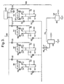
- FIG 1a there is shown a reactor block 10 suitable for use in a Fischer-Tropsch reactor module 50 (see figure 2 ), the reactor block 10 being shown in section and only in part.
- the reactor block 10 consists of a stack of flat plates 12 of thickness 1 mm spaced apart so as to define channels 15 for a coolant fluid alternating with channels 17 for the Fischer-Tropsch synthesis.
- the coolant channels 15 are defined by sheets 14 of thickness 0.75 mm shaped into flat-topped sawtooth corrugations.
- the height of the corrugations (typically in the range 1 to 4 mm) is 2 mm in this example, and correspondingly thick solid edge strips 16 are provided along the sides, and the wavelength of the corrugations is 12 mm (the arrangement being described in more detail below).
- the channels 17 for the Fischer-Tropsch synthesis are of height 5 mm (typically within a range of 2 mm to 10 mm), being defined by bars 18 of square or rectangular cross-section, 5 mm high, spaced apart by 80 mm (the spacing typically being in a range of 20 - 100 mm) and so defining straight through channels.
- a corrugated 50 ⁇ m thick foil 20 typically of thickness in the range from 20-150 ⁇ m
- a ceramic coating acting as a support for the catalytic material only two such foils 20 are shown.
- the reactor block 10 may be made by stacking the components that define the channels 15 and 17, and then bonding them together for example by brazing or by diffusion bonding. The reactor block 10 is then turned through 90° so that the channels 15 and 17 are upright, and the catalyst carrying foils 20 are inserted into the channels 17.
- FIG. 1b there is shown an alternative reactor block 110 suitable for use in a Fischer-Tropsch reactor module, the reactor block 110 being shown in section and only in part.
- the reactor block 110 resembles the reactor block 10, identical components being referred to by the same reference numerals.
- the reactor block 110 consists of a stack of flat plates 12 of thickness 1 mm spaced apart so as to define channels 15 for a coolant fluid alternating with channels 117 for the Fischer-Tropsch synthesis.
- the coolant channels 15 are defined in addition by sheets 14 of thickness 0.75 mm shaped into flat-topped sawtooth corrugations as described above, with solid edge strips 16.
- the channels 117 for the Fischer-Tropsch synthesis are sealed by solid edge bars 18 and are defined in addition by sheets 119 of thickness 1.0 mm shaped into castellations of height in the range of 4 mm to 12 mm, preferably 5 mm.
- the resulting channels 117 are of width 10 mm and of height 5 mm and extend straight through the stack from one face to the opposite face.
- the channels 15 and 117 in reactor block 110 extend in parallel.
- the reactor block 110 may be made by stacking the components that define the channels 15 and 117, and then bonding them together for example by brazing. The reactor block 110 is then turned through 90° so that the channels 15 and 117 are upright, and the catalyst carrying foils 120 are inserted into the channels 117.
- the catalyst inserts 20 or 120 are shown as single corrugated foils of the height of the channel 17 or 117, but might instead consist of a stack of corrugated foils and substantially flat foils.
- the channels 117 have their largest transverse dimension parallel to the plane of the plates 12.
- the channels may have their largest transverse dimension perpendicular to the plane of the plates 12.
- the width of the channels is preferably between about 4 and 20 mm.
- Each plate 12 may for example be 1.3 m by 1.3 m, or 1.2 m by 0.8 m, so the channels 17 or 117 would be 1.3 m long or 0.8 m long, respectively.
- the channels 17 or 117 are no more than 1.5 m long, and preferably at least 0.3 m long.
- the reactor module 50 incorporating the reactor block 10 is shown in vertical cross-section, with the reactor block 10 partly broken away.
- the reactor block 10 consists of a stack of flat plates 12 separated from each other to define the flow channels 15 and 17.
- the channels 17 for the Fischer-Tropsch reaction contain catalyst-carrying corrugated foils 20, and extend straight through the reactor block 10 (from top to bottom), the top face being open, and at the bottom face the channels 17 communicate with a header 24.
- the reaction products flow out of the header 24 through a duct 25.
- the flat plates 12 are held apart by the edge strips 16 around the perimeter of the plate 12, and in the central section also by the corrugated sheets 14.
- each corrugated sheet 14 is an end portion 26, enclosed by the edge strips 16 apart from a gap on one side, so that the end portion 26 communicates with a respective header 28 or 30; these extend the length of the reactor block 10 and are attached to its sides near diametrically opposite corners, top left and bottom right as shown.
- the coolant fluid is supplied to the header 28 and withdrawn through the header 30, and the end portions 26 distribute the coolant between the header 28 or 30 and the coolant channels 15.
- the coolant is supplied to the header 28 from a duct 32, and is removed from the header 30 by a duct 34, so the flow is generally co-current relative to the flow in the Fischer-Tropsch channels 17.
- the flat plates 12, the edge strips 16, the bars 18, and the corrugated sheets 14 may be of aluminium alloy, for example 3003 grade (aluminium with about 1.2% manganese and 0.1% copper).
- the synthesis gas is supplied to the top face of the reactor block 10 through a header 40, although it will be appreciated that other supply means may be used with the reactor block 10. Synthesis gas is supplied to the header 40 through a pipe 42.
- the coolant may be supplied at such a flow rate that the coolant temperature increases by a preset amount such as 10 K on passing through the reactor 50; arranging for the coolant to flow co-current relative to the Fischer-Tropsch channels 17 (apart from the coolant flow in the distributing end portions 26) helps to minimise the temperature difference across any two points in any horizontal plane through the cooling channels of the reactor block 10.
- the reactor block 10 might be of overall length over 1 m, say 8 m, and its cross-sectional area is that of one of the plates 12.
- the reactor module 50 incorporating the reactor block 10 may weigh no more than 25 tonnes, so it can be handled by conventional cargo handling equipment. It may have sufficient capacity to produce about 32 m 3 /day (200 barrels/day) of long chain hydrocarbons.
- the Fischer-Tropsch reactor module 50 may form part of a plant for processing natural gas to obtain longer chain hydrocarbons, the plant incorporating means for forming synthesis gas from methane, and means for subjecting the synthesis gas to Fischer-Tropsch synthesis to generate longer-chain hydrocarbons.
- This process can be carried out at an oil well, for example to treat associated gas.
- the flow rate of associated gas can be expected to vary significantly through the operating life of the oil well, and it is therefore desirable to be able to accommodate changes or fluctuations in the flow rate of associated gas.
- Synthesis gas at a suitable pressure (say 2.6 MPa) is provided through a feed duct 60, through which it is supplied to the inlet pipe 42 of each reactor module 50.
- Coolant fluid is circulated through the coolant channels and recirculated via a temperature control system 44 (represented diagrammatically), ensuring that the temperature difference between the inlet 32 and outlet 34 for the coolant is no more than say 10 K, and that the average temperature of the reactor 50 remains constant.
- a temperature control system 44 represented diagrammatically
- the performance of a Fischer-Tropsch reactor depends upon the reaction temperature.
- the performance of the reactor is determined by the mean temperature.
- the temperature control system 44 includes a control circuit to ensure that the mean coolant temperature has the value so as to achieve a predetermined conversion, and the mean temperature should not differ by more than 2 K from this set point value, preferably not differing by more than 1 K.
- This control is achieved by controlling the temperature of the coolant supplied to the reactor module 50, and fine adjustment of the mean temperature is obtained by adjusting the flow rate, since the temperature difference between inlet and outlet on the process side is directly related to the corresponding temperature difference on the coolant side.
- the coolant flow rate is also controlled to ensure that the temperature difference between the inflowing and outflowing coolant does not exceed a preset limit; this limit may be 10 K or less, for example 7 K or 5 K.
- the fluid mixture containing reaction products emerges through the ducts 25 from the Fischer-Tropsch reactor modules 50, and is cooled by passage through a heat exchanger 46 to condense water vapour and longer chain hydrocarbons. This is then separated by a separator 48 into water, liquid hydrocarbons C5+, and remaining tail gases 64.
- the coolant used for the heat exchanger 46 may be water, and may be at ambient temperature, say about 20 or 30°C, or preferably somewhat warmer, say between 60 and 80°C to ensure no waxing of the heat exchanger surfaces.
- the combination of the reactor modules 50, the heat exchanger 46 and the separator 48 may be referred to as a synthesis assembly 66.
- the tail gas 64 from the separator 48 is then fed through a second synthesis assembly 66 to convert remaining hydrogen and carbon monoxide to additional longer chain hydrocarbons C5+.
- the plant may consist of a plurality of such synthesis assemblies 66, so as to carry out Fischer-Tropsch synthesis in a plurality of stages. The number of stages depends on the proportion of the synthesis gas that undergoes Fischer-Tropsch synthesis in each stage.
- Each module 50 in this plant is provided with shut-off valves 55 or pairs of shut-off valves 55 so the flows of synthesis gas in and out can be turned off to that individual reactor module 50 without preventing operation of the remainder of the plant.
- Valves 56 also enable the coolant to be turned off. Hence if the flow rate of associated gas changes, the capacity of the plant to perform Fischer-Tropsch synthesis can be adjusted accordingly by changing the number of reactor modules 50 in use.
- shut-off valves 55 When it is necessary to shut off one of the Fischer-Tropsch reactor modules 50, the shut-off valves 55 are both closed, but at the same time the reactor module 50 is flushed through with a shutdown gas at the Fischer-Tropsch channel operating pressure (2.6 MPa in this example) from a shutdown gas supply 58, to remove any remaining synthesis gas.
- the shutdown gas supply 58 is connected via shut-off valves 59 (which are normally closed) to each reactor module 50, but only the connections to one reactor module 50 are shown. After flushing out the synthesis gas, the reactor module 50 is then closed in at this operating pressure by also closing the shut-off valves 59. This ensures that the catalyst does not deteriorate.
- the shutdown gas is a gas that is not involved in the catalytic reaction, thereby substantially preventing further catalytic activity in the reactor. Examples of suitable gases include pure methane, desulphurised natural gas, and nitrogen.
- This procedure also enables individual reactor modules 50 to be removed and replaced, while not in use, for example if a reactor module 50 needs to be refurbished for example to replace spent catalysts. It will be appreciated that such a reactor module 50 that has been removed from the plant, and has been subsequently depressurised, can readily be dismantled by disconnecting the header 40 from the reactor block 10. The catalyst carrying foils 20 can then be withdrawn through the open ends of the channels 17.
- the reactor block 10 and the reactor module 50 described above are by way of example only, and that they may be modified in many ways while remaining within the scope of the present invention.
- the plates may be of a different shape and size, and the flow channels 15 and 17 (or 117) may have a different cross-sectional shape to those described above, for example the corrugated sheet 14 might have castellated corrugations.
- the catalyst structure is shown as a single corrugated foil 20 or 120, but it may instead for example be an assembly of two corrugated foils with a flat foil between them or three corrugated foils with two flats between them.
- the catalyst structure may extend the entire length of the channel 17 or 117, or may for example extend only along that part of the channel that is adjacent to a coolant channel 15.
Landscapes
- Chemical & Material Sciences (AREA)
- Oil, Petroleum & Natural Gas (AREA)
- Organic Chemistry (AREA)
- Chemical Kinetics & Catalysis (AREA)
- Engineering & Computer Science (AREA)
- General Chemical & Material Sciences (AREA)
- Organic Low-Molecular-Weight Compounds And Preparation Thereof (AREA)
- Catalysts (AREA)
- Low-Molecular Organic Synthesis Reactions Using Catalysts (AREA)
- Production Of Liquid Hydrocarbon Mixture For Refining Petroleum (AREA)
- Devices And Processes Conducted In The Presence Of Fluids And Solid Particles (AREA)
- Physical Or Chemical Processes And Apparatus (AREA)
Applications Claiming Priority (2)
| Application Number | Priority Date | Filing Date | Title |
|---|---|---|---|
| GBGB0725140.8A GB0725140D0 (en) | 2007-12-24 | 2007-12-24 | Catalytic Reactor |
| PCT/GB2008/050855 WO2009081175A1 (en) | 2007-12-24 | 2008-09-24 | Catalytic reactor |
Publications (2)
| Publication Number | Publication Date |
|---|---|
| EP2227325A1 EP2227325A1 (en) | 2010-09-15 |
| EP2227325B1 true EP2227325B1 (en) | 2015-01-07 |
Family
ID=39048685
Family Applications (1)
| Application Number | Title | Priority Date | Filing Date |
|---|---|---|---|
| EP08806671.7A Active EP2227325B1 (en) | 2007-12-24 | 2008-09-24 | Catalytic reactor |
Country Status (14)
| Country | Link |
|---|---|
| US (1) | US8444939B2 (zh) |
| EP (1) | EP2227325B1 (zh) |
| JP (1) | JP5571573B2 (zh) |
| KR (1) | KR20100101158A (zh) |
| CN (1) | CN101932379B (zh) |
| AU (1) | AU2008339634B2 (zh) |
| BR (1) | BRPI0821525A8 (zh) |
| CA (1) | CA2708821C (zh) |
| DK (1) | DK2227325T3 (zh) |
| EA (1) | EA019964B1 (zh) |
| GB (1) | GB0725140D0 (zh) |
| MY (1) | MY157456A (zh) |
| WO (1) | WO2009081175A1 (zh) |
| ZA (1) | ZA201004401B (zh) |
Families Citing this family (27)
| Publication number | Priority date | Publication date | Assignee | Title |
|---|---|---|---|---|
| US20050171217A1 (en) * | 2001-12-05 | 2005-08-04 | Bowe Michael J. | Process and apparatus for steam-methane reforming |
| WO2009044198A1 (en) * | 2007-10-02 | 2009-04-09 | Compact Gtl Plc | Gas-to-liquid plant using parallel units |
| GB0915036D0 (en) * | 2009-08-28 | 2009-09-30 | Compactgtl Plc | Catalytic reaction module |
| JP5581028B2 (ja) * | 2009-09-16 | 2014-08-27 | 住友精密工業株式会社 | 触媒反応器 |
| KR101031886B1 (ko) | 2009-10-07 | 2011-05-02 | 한국에너지기술연구원 | Ft 슬러리 기포탑 반응기의 반응열 제거용 혼합형 냉각장치 |
| GB0918738D0 (en) * | 2009-10-26 | 2009-12-09 | Compactgtl Plc | Reactor with channels |
| KR101297597B1 (ko) * | 2011-04-19 | 2013-08-19 | 한국화학연구원 | 합성가스로부터 탄화수소를 제조하기 위한 반응장치 |
| GB201107070D0 (en) * | 2011-04-27 | 2011-06-08 | Davy Process Techn Ltd | FT process using can reactor |
| GB201112028D0 (en) * | 2011-07-13 | 2011-08-31 | Gas2 Ltd | Fixed bed fischer tropsch reactor |
| WO2013117948A1 (en) * | 2012-02-06 | 2013-08-15 | Helbio Societé Anonyme Hydrogen And Energy Production Systems | Heat integrated reformer with catalytic combustion for hydrogen production |
| US11607657B2 (en) | 2012-02-06 | 2023-03-21 | Helbio S.A. | Heat integrated reformer with catalytic combustion for hydrogen production |
| EP2814910A4 (en) | 2012-02-17 | 2015-11-11 | Ceramatec Inc | EXTENDED FISCHER TROPSCH SYSTEM |
| EP2817090A4 (en) | 2012-02-21 | 2016-01-20 | Ceramatec Inc | COMPACT FISCHER TROPSCH SYSTEM WITH INTEGRATED PRIMARY AND SECONDARY BED TEMPERATURE CONTROL |
| US9162935B2 (en) | 2012-02-21 | 2015-10-20 | Ceramatec, Inc. | Compact FT combined with micro-fibrous supported nano-catalyst |
| JP2015517175A (ja) | 2012-03-08 | 2015-06-18 | ヘルビオ ソシエテ アノニム ハイドロジェン アンド エナジー プロダクション システムズ | 燃料電池のための触媒を支持する置換可能な構造化支持部を含む触媒加熱式燃料処理装置 |
| US9255746B2 (en) | 2012-10-26 | 2016-02-09 | Modine Manufacturing Company | Reactor core for use in a chemical reactor, and method of making the same |
| GB201302301D0 (en) * | 2013-02-08 | 2013-03-27 | Process Systems Entpr Ltd | Reactor and reaction method |
| US9676623B2 (en) | 2013-03-14 | 2017-06-13 | Velocys, Inc. | Process and apparatus for conducting simultaneous endothermic and exothermic reactions |
| JP6376131B2 (ja) * | 2013-09-13 | 2018-08-22 | 株式会社Ihi | リアクタ |
| US10286372B2 (en) | 2014-05-12 | 2019-05-14 | Univation Technologies, Llc | Systems and methods using an insert assembly with stacked gas flow gaps |
| KR102003429B1 (ko) * | 2016-10-19 | 2019-07-24 | 주식회사 포스코건설 | 합성석유 제조장치 및 제조방법 |
| US10543470B2 (en) | 2017-04-28 | 2020-01-28 | Intramicron, Inc. | Reactors and methods for processes involving partial oxidation reactions |
| US10544371B2 (en) | 2018-05-11 | 2020-01-28 | Intramicron, Inc. | Channel reactors |
| JP7271865B2 (ja) * | 2018-05-17 | 2023-05-12 | 株式会社Ihi | 反応装置 |
| EP3599075A1 (de) | 2018-07-27 | 2020-01-29 | Siemens Aktiengesellschaft | Reaktor zur durchführung einer chemischen gleichgewichtsreaktion |
| CN112221439A (zh) * | 2020-09-09 | 2021-01-15 | 中石化宁波工程有限公司 | 用于微通道反应器的分布板及具有其的微通道反应器 |
| CN113345611B (zh) * | 2021-05-11 | 2022-12-13 | 哈尔滨工程大学 | 一种板型燃料元件多矩形流道均匀释热模拟试验装置 |
Family Cites Families (11)
| Publication number | Priority date | Publication date | Assignee | Title |
|---|---|---|---|---|
| GB1116345A (en) * | 1964-06-16 | 1968-06-06 | Marston Excelsior Ltd | Improvements in or relating to chemical catalytic reactors and like process vessels in which fluids are contacted with solid materials |
| ZA782775B (en) * | 1977-06-27 | 1979-05-30 | Minnesota Mining & Mfg | Catalytic reactor for isothermal reactions |
| GB2223237B (en) * | 1988-07-21 | 1992-09-16 | Shell Int Research | Shut-down process for a fischer-tropsch reactor, and said reactor |
| GB0116894D0 (en) * | 2001-07-11 | 2001-09-05 | Accentus Plc | Catalytic reactor |
| GB0124999D0 (en) * | 2001-10-18 | 2001-12-05 | Accentus Plc | Catalytic reactor |
| US20050171217A1 (en) | 2001-12-05 | 2005-08-04 | Bowe Michael J. | Process and apparatus for steam-methane reforming |
| DE60307885T3 (de) * | 2002-12-02 | 2010-12-16 | Compactgtl Plc, Abingdon | Katalytisches verfahren |
| GB0413400D0 (en) * | 2004-06-16 | 2004-07-21 | Accentus Plc | Catalytic plant and process |
| GB0501731D0 (en) * | 2005-01-31 | 2005-03-02 | Accentus Plc | Catalytic reactor |
| GB0504622D0 (en) * | 2005-03-05 | 2005-04-13 | Accentus Plc | Catalytic reactors |
| WO2007129109A2 (en) | 2006-05-08 | 2007-11-15 | Compactgtl Plc | Catalytic reactor comprising first and secondary flow channels arranged alternately |
-
2007
- 2007-12-24 GB GBGB0725140.8A patent/GB0725140D0/en not_active Ceased
-
2008
- 2008-09-24 CA CA2708821A patent/CA2708821C/en active Active
- 2008-09-24 US US12/810,128 patent/US8444939B2/en active Active - Reinstated
- 2008-09-24 MY MYPI2010002898A patent/MY157456A/en unknown
- 2008-09-24 CN CN200880123322.8A patent/CN101932379B/zh active Active
- 2008-09-24 KR KR1020107016437A patent/KR20100101158A/ko not_active Application Discontinuation
- 2008-09-24 BR BRPI0821525A patent/BRPI0821525A8/pt active Search and Examination
- 2008-09-24 AU AU2008339634A patent/AU2008339634B2/en active Active
- 2008-09-24 WO PCT/GB2008/050855 patent/WO2009081175A1/en active Application Filing
- 2008-09-24 JP JP2010540174A patent/JP5571573B2/ja active Active
- 2008-09-24 DK DK08806671.7T patent/DK2227325T3/da active
- 2008-09-24 EA EA201070797A patent/EA019964B1/ru not_active IP Right Cessation
- 2008-09-24 EP EP08806671.7A patent/EP2227325B1/en active Active
-
2010
- 2010-06-22 ZA ZA2010/04401A patent/ZA201004401B/en unknown
Also Published As
| Publication number | Publication date |
|---|---|
| US20100324158A1 (en) | 2010-12-23 |
| GB0725140D0 (en) | 2008-01-30 |
| JP5571573B2 (ja) | 2014-08-13 |
| DK2227325T3 (da) | 2014-06-30 |
| ZA201004401B (en) | 2011-08-31 |
| CN101932379A (zh) | 2010-12-29 |
| US8444939B2 (en) | 2013-05-21 |
| CA2708821A1 (en) | 2009-07-02 |
| BRPI0821525A2 (pt) | 2015-06-16 |
| CA2708821C (en) | 2015-12-29 |
| EA019964B1 (ru) | 2014-07-30 |
| MY157456A (en) | 2016-06-15 |
| CN101932379B (zh) | 2014-06-04 |
| EP2227325A1 (en) | 2010-09-15 |
| AU2008339634B2 (en) | 2012-12-06 |
| WO2009081175A1 (en) | 2009-07-02 |
| AU2008339634A1 (en) | 2009-07-02 |
| BRPI0821525A8 (pt) | 2016-03-22 |
| EA201070797A1 (ru) | 2010-12-30 |
| KR20100101158A (ko) | 2010-09-16 |
| JP2011508043A (ja) | 2011-03-10 |
Similar Documents
| Publication | Publication Date | Title |
|---|---|---|
| EP2227325B1 (en) | Catalytic reactor | |
| US7235218B2 (en) | Catalytic reactors | |
| EP1756249B1 (en) | Catalytic plant and process for performing fischer-tropsch synthesis | |
| CA2593609C (en) | Catalytic reactor | |
| CA2597161C (en) | Catalytic reactors | |
| US20080226517A1 (en) | Catalytic Reactor | |
| US20040251001A1 (en) | Catalytic reactor | |
| MX2007008996A (es) | Reactor catalitico. | |
| US20120142789A1 (en) | Catalytic Reaction Module | |
| CA2660469A1 (en) | Compact reactor | |
| WO2007003959A1 (en) | Producing liquid hydrocarbons | |
| GB2441509A (en) | Fischer-Tropsch synthesis | |
| TW201039919A (en) | Catalytic reactor | |
| WO2013034934A1 (en) | Catalytic method using a plate-type reactor | |
| WO2013076460A1 (en) | Removal of carbon from a catalytic reaction module |
Legal Events
| Date | Code | Title | Description |
|---|---|---|---|
| PUAI | Public reference made under article 153(3) epc to a published international application that has entered the european phase |
Free format text: ORIGINAL CODE: 0009012 |
|
| 17P | Request for examination filed |
Effective date: 20100614 |
|
| AK | Designated contracting states |
Kind code of ref document: A1 Designated state(s): AT BE BG CH CY CZ DE DK EE ES FI FR GB GR HR HU IE IS IT LI LT LU LV MC MT NL NO PL PT RO SE SI SK TR |
|
| AX | Request for extension of the european patent |
Extension state: AL BA MK RS |
|
| 17Q | First examination report despatched |
Effective date: 20101222 |
|
| DAX | Request for extension of the european patent (deleted) | ||
| RAP1 | Party data changed (applicant data changed or rights of an application transferred) |
Owner name: COMPACTGTL LIMITED |
|
| GRAP | Despatch of communication of intention to grant a patent |
Free format text: ORIGINAL CODE: EPIDOSNIGR1 |
|
| INTG | Intention to grant announced |
Effective date: 20131205 |
|
| GRAS | Grant fee paid |
Free format text: ORIGINAL CODE: EPIDOSNIGR3 |
|
| GRAA | (expected) grant |
Free format text: ORIGINAL CODE: 0009210 |
|
| AK | Designated contracting states |
Kind code of ref document: B1 Designated state(s): AT BE BG CH CY CZ DE DK EE ES FI FR GB GR HR HU IE IS IT LI LT LU LV MC MT NL NO PL PT RO SE SI SK TR |
|
| REG | Reference to a national code |
Ref country code: GB Ref legal event code: FG4D Ref country code: CH Ref legal event code: EP |
|
| REG | Reference to a national code |
Ref country code: AT Ref legal event code: REF Ref document number: 664709 Country of ref document: AT Kind code of ref document: T Effective date: 20140515 |
|
| REG | Reference to a national code |
Ref country code: IE Ref legal event code: FG4D |
|
| REG | Reference to a national code |
Ref country code: DE Ref legal event code: R096 Ref document number: 602008031905 Country of ref document: DE Effective date: 20140612 |
|
| REG | Reference to a national code |
Ref country code: DK Ref legal event code: T3 Effective date: 20140626 |
|
| PUAC | Information related to the publication of a b1 document modified or deleted |
Free format text: ORIGINAL CODE: 0009299EPPU |
|
| REG | Reference to a national code |
Ref country code: CH Ref legal event code: PK Free format text: DIE ERTEILUNG WURDE VOM EPA WIDERRUFEN. |
|
| 29U | Proceedings interrupted after grant according to rule 142 epc |
Effective date: 20140108 |
|
| 29W | Proceedings resumed after grant [after interruption of proceedings according to rule 142 epc] |
Effective date: 20141001 |
|
| REG | Reference to a national code |
Ref country code: NL Ref legal event code: T3 |
|
| DB1 | Publication of patent cancelled |
Effective date: 20140711 |
|
| REG | Reference to a national code |
Ref country code: NL Ref legal event code: GRER Effective date: 20140814 |
|
| REG | Reference to a national code |
Ref country code: DE Ref legal event code: R107 Ref document number: 602008031905 Country of ref document: DE Effective date: 20140904 |
|
| GRAJ | Information related to disapproval of communication of intention to grant by the applicant or resumption of examination proceedings by the epo deleted |
Free format text: ORIGINAL CODE: EPIDOSDIGR1 |
|
| GRAP | Despatch of communication of intention to grant a patent |
Free format text: ORIGINAL CODE: EPIDOSNIGR1 |
|
| INTG | Intention to grant announced |
Effective date: 20141029 |
|
| GRAS | Grant fee paid |
Free format text: ORIGINAL CODE: EPIDOSNIGR3 |
|
| GRAA | (expected) grant |
Free format text: ORIGINAL CODE: 0009210 |
|
| AK | Designated contracting states |
Kind code of ref document: B1 Designated state(s): AT BE BG CH CY CZ DE DK EE ES FI FR GB GR HR HU IE IS IT LI LT LU LV MC MT NL NO PL PT RO SE SI SK TR |
|
| REG | Reference to a national code |
Ref country code: GB Ref legal event code: FG4D |
|
| REG | Reference to a national code |
Ref country code: CH Ref legal event code: EP Ref country code: CH Ref legal event code: PK Free format text: DIE ERTEILUNG VOM 30.04.2014 WURDE VOM EPA WIDERRUFEN |
|
| REG | Reference to a national code |
Ref country code: NL Ref legal event code: T3 |
|
| REG | Reference to a national code |
Ref country code: DE Ref legal event code: R096 Ref document number: 602008031905 Country of ref document: DE Effective date: 20150219 |
|
| REG | Reference to a national code |
Ref country code: NO Ref legal event code: T2 Effective date: 20150107 |
|
| REG | Reference to a national code |
Ref country code: LT Ref legal event code: MG4D |
|
| PG25 | Lapsed in a contracting state [announced via postgrant information from national office to epo] |
Ref country code: LT Free format text: LAPSE BECAUSE OF FAILURE TO SUBMIT A TRANSLATION OF THE DESCRIPTION OR TO PAY THE FEE WITHIN THE PRESCRIBED TIME-LIMIT Effective date: 20150107 Ref country code: HR Free format text: LAPSE BECAUSE OF FAILURE TO SUBMIT A TRANSLATION OF THE DESCRIPTION OR TO PAY THE FEE WITHIN THE PRESCRIBED TIME-LIMIT Effective date: 20150107 Ref country code: FI Free format text: LAPSE BECAUSE OF FAILURE TO SUBMIT A TRANSLATION OF THE DESCRIPTION OR TO PAY THE FEE WITHIN THE PRESCRIBED TIME-LIMIT Effective date: 20150107 |
|
| PG25 | Lapsed in a contracting state [announced via postgrant information from national office to epo] |
Ref country code: LV Free format text: LAPSE BECAUSE OF FAILURE TO SUBMIT A TRANSLATION OF THE DESCRIPTION OR TO PAY THE FEE WITHIN THE PRESCRIBED TIME-LIMIT Effective date: 20150107 |
|
| REG | Reference to a national code |
Ref country code: DE Ref legal event code: R097 Ref document number: 602008031905 Country of ref document: DE |
|
| PG25 | Lapsed in a contracting state [announced via postgrant information from national office to epo] |
Ref country code: MC Free format text: LAPSE BECAUSE OF FAILURE TO SUBMIT A TRANSLATION OF THE DESCRIPTION OR TO PAY THE FEE WITHIN THE PRESCRIBED TIME-LIMIT Effective date: 20150107 Ref country code: EE Free format text: LAPSE BECAUSE OF FAILURE TO SUBMIT A TRANSLATION OF THE DESCRIPTION OR TO PAY THE FEE WITHIN THE PRESCRIBED TIME-LIMIT Effective date: 20150107 Ref country code: CZ Free format text: LAPSE BECAUSE OF FAILURE TO SUBMIT A TRANSLATION OF THE DESCRIPTION OR TO PAY THE FEE WITHIN THE PRESCRIBED TIME-LIMIT Effective date: 20150107 Ref country code: SK Free format text: LAPSE BECAUSE OF FAILURE TO SUBMIT A TRANSLATION OF THE DESCRIPTION OR TO PAY THE FEE WITHIN THE PRESCRIBED TIME-LIMIT Effective date: 20150107 |
|
| PLBE | No opposition filed within time limit |
Free format text: ORIGINAL CODE: 0009261 |
|
| STAA | Information on the status of an ep patent application or granted ep patent |
Free format text: STATUS: NO OPPOSITION FILED WITHIN TIME LIMIT |
|
| 26N | No opposition filed |
Effective date: 20151008 |
|
| PG25 | Lapsed in a contracting state [announced via postgrant information from national office to epo] |
Ref country code: SI Free format text: LAPSE BECAUSE OF FAILURE TO SUBMIT A TRANSLATION OF THE DESCRIPTION OR TO PAY THE FEE WITHIN THE PRESCRIBED TIME-LIMIT Effective date: 20150107 |
|
| REG | Reference to a national code |
Ref country code: DE Ref legal event code: R119 Ref document number: 602008031905 Country of ref document: DE |
|
| REG | Reference to a national code |
Ref country code: CH Ref legal event code: PL |
|
| PG25 | Lapsed in a contracting state [announced via postgrant information from national office to epo] |
Ref country code: BE Free format text: LAPSE BECAUSE OF FAILURE TO SUBMIT A TRANSLATION OF THE DESCRIPTION OR TO PAY THE FEE WITHIN THE PRESCRIBED TIME-LIMIT Effective date: 20150107 |
|
| REG | Reference to a national code |
Ref country code: IE Ref legal event code: MM4A |
|
| REG | Reference to a national code |
Ref country code: FR Ref legal event code: ST Effective date: 20160531 |
|
| PG25 | Lapsed in a contracting state [announced via postgrant information from national office to epo] |
Ref country code: CH Free format text: LAPSE BECAUSE OF NON-PAYMENT OF DUE FEES Effective date: 20150930 Ref country code: LI Free format text: LAPSE BECAUSE OF NON-PAYMENT OF DUE FEES Effective date: 20150930 Ref country code: IE Free format text: LAPSE BECAUSE OF NON-PAYMENT OF DUE FEES Effective date: 20150924 |
|
| PG25 | Lapsed in a contracting state [announced via postgrant information from national office to epo] |
Ref country code: FR Free format text: LAPSE BECAUSE OF NON-PAYMENT OF DUE FEES Effective date: 20150930 |
|
| PG25 | Lapsed in a contracting state [announced via postgrant information from national office to epo] |
Ref country code: MT Free format text: LAPSE BECAUSE OF FAILURE TO SUBMIT A TRANSLATION OF THE DESCRIPTION OR TO PAY THE FEE WITHIN THE PRESCRIBED TIME-LIMIT Effective date: 20150107 |
|
| PG25 | Lapsed in a contracting state [announced via postgrant information from national office to epo] |
Ref country code: BG Free format text: LAPSE BECAUSE OF FAILURE TO SUBMIT A TRANSLATION OF THE DESCRIPTION OR TO PAY THE FEE WITHIN THE PRESCRIBED TIME-LIMIT Effective date: 20150107 Ref country code: HU Free format text: LAPSE BECAUSE OF FAILURE TO SUBMIT A TRANSLATION OF THE DESCRIPTION OR TO PAY THE FEE WITHIN THE PRESCRIBED TIME-LIMIT; INVALID AB INITIO Effective date: 20080924 Ref country code: DE Free format text: LAPSE BECAUSE OF NON-PAYMENT OF DUE FEES Effective date: 20160401 Ref country code: RO Free format text: LAPSE BECAUSE OF FAILURE TO SUBMIT A TRANSLATION OF THE DESCRIPTION OR TO PAY THE FEE WITHIN THE PRESCRIBED TIME-LIMIT Effective date: 20150107 |
|
| PG25 | Lapsed in a contracting state [announced via postgrant information from national office to epo] |
Ref country code: SE Free format text: LAPSE BECAUSE OF NON-PAYMENT OF DUE FEES Effective date: 20150107 Ref country code: CY Free format text: LAPSE BECAUSE OF FAILURE TO SUBMIT A TRANSLATION OF THE DESCRIPTION OR TO PAY THE FEE WITHIN THE PRESCRIBED TIME-LIMIT Effective date: 20150107 Ref country code: GR Free format text: LAPSE BECAUSE OF FAILURE TO SUBMIT A TRANSLATION OF THE DESCRIPTION OR TO PAY THE FEE WITHIN THE PRESCRIBED TIME-LIMIT Effective date: 20150107 Ref country code: IS Free format text: LAPSE BECAUSE OF NON-PAYMENT OF DUE FEES Effective date: 20150107 Ref country code: ES Free format text: LAPSE BECAUSE OF FAILURE TO SUBMIT A TRANSLATION OF THE DESCRIPTION OR TO PAY THE FEE WITHIN THE PRESCRIBED TIME-LIMIT Effective date: 20150107 |
|
| PG25 | Lapsed in a contracting state [announced via postgrant information from national office to epo] |
Ref country code: AT Free format text: LAPSE BECAUSE OF FAILURE TO SUBMIT A TRANSLATION OF THE DESCRIPTION OR TO PAY THE FEE WITHIN THE PRESCRIBED TIME-LIMIT Effective date: 20150107 Ref country code: IT Free format text: LAPSE BECAUSE OF NON-PAYMENT OF DUE FEES Effective date: 20150107 |
|
| PG25 | Lapsed in a contracting state [announced via postgrant information from national office to epo] |
Ref country code: TR Free format text: LAPSE BECAUSE OF FAILURE TO SUBMIT A TRANSLATION OF THE DESCRIPTION OR TO PAY THE FEE WITHIN THE PRESCRIBED TIME-LIMIT Effective date: 20150107 |
|
| PG25 | Lapsed in a contracting state [announced via postgrant information from national office to epo] |
Ref country code: LU Free format text: LAPSE BECAUSE OF NON-PAYMENT OF DUE FEES Effective date: 20150924 |
|
| PG25 | Lapsed in a contracting state [announced via postgrant information from national office to epo] |
Ref country code: PL Free format text: LAPSE BECAUSE OF NON-PAYMENT OF DUE FEES Effective date: 20150107 |
|
| PG25 | Lapsed in a contracting state [announced via postgrant information from national office to epo] |
Ref country code: PT Free format text: LAPSE BECAUSE OF FAILURE TO SUBMIT A TRANSLATION OF THE DESCRIPTION OR TO PAY THE FEE WITHIN THE PRESCRIBED TIME-LIMIT Effective date: 20150107 |
|
| PGFP | Annual fee paid to national office [announced via postgrant information from national office to epo] |
Ref country code: NL Payment date: 20240320 Year of fee payment: 16 |
|
| PGFP | Annual fee paid to national office [announced via postgrant information from national office to epo] |
Ref country code: GB Payment date: 20240229 Year of fee payment: 16 |
|
| PGFP | Annual fee paid to national office [announced via postgrant information from national office to epo] |
Ref country code: NO Payment date: 20240313 Year of fee payment: 16 Ref country code: DK Payment date: 20240312 Year of fee payment: 16 |