EP2226695A1 - Verfahren und Vorrichtung zur Identifizierung fehlerhafter Sensorausgaben - Google Patents
Verfahren und Vorrichtung zur Identifizierung fehlerhafter Sensorausgaben Download PDFInfo
- Publication number
- EP2226695A1 EP2226695A1 EP09179539A EP09179539A EP2226695A1 EP 2226695 A1 EP2226695 A1 EP 2226695A1 EP 09179539 A EP09179539 A EP 09179539A EP 09179539 A EP09179539 A EP 09179539A EP 2226695 A1 EP2226695 A1 EP 2226695A1
- Authority
- EP
- European Patent Office
- Prior art keywords
- samples
- sample
- sensor
- erroneous
- mean
- Prior art date
- Legal status (The legal status is an assumption and is not a legal conclusion. Google has not performed a legal analysis and makes no representation as to the accuracy of the status listed.)
- Withdrawn
Links
Images

Classifications
-
- G—PHYSICS
- G01—MEASURING; TESTING
- G01D—MEASURING NOT SPECIALLY ADAPTED FOR A SPECIFIC VARIABLE; ARRANGEMENTS FOR MEASURING TWO OR MORE VARIABLES NOT COVERED IN A SINGLE OTHER SUBCLASS; TARIFF METERING APPARATUS; MEASURING OR TESTING NOT OTHERWISE PROVIDED FOR
- G01D21/00—Measuring or testing not otherwise provided for
-
- G—PHYSICS
- G01—MEASURING; TESTING
- G01D—MEASURING NOT SPECIALLY ADAPTED FOR A SPECIFIC VARIABLE; ARRANGEMENTS FOR MEASURING TWO OR MORE VARIABLES NOT COVERED IN A SINGLE OTHER SUBCLASS; TARIFF METERING APPARATUS; MEASURING OR TESTING NOT OTHERWISE PROVIDED FOR
- G01D1/00—Measuring arrangements giving results other than momentary value of variable, of general application
-
- G—PHYSICS
- G01—MEASURING; TESTING
- G01D—MEASURING NOT SPECIALLY ADAPTED FOR A SPECIFIC VARIABLE; ARRANGEMENTS FOR MEASURING TWO OR MORE VARIABLES NOT COVERED IN A SINGLE OTHER SUBCLASS; TARIFF METERING APPARATUS; MEASURING OR TESTING NOT OTHERWISE PROVIDED FOR
- G01D15/00—Component parts of recorders for measuring arrangements not specially adapted for a specific variable
Definitions
- the disclosure relates to obtaining sensor data, and, more particularly, evaluating the sensor data.
- Data received from a sensor measuring a real world physical quantity likely contains accurate measurement data as well as erroneous data. Sensors often generate erroneous data due to noise in the measurement environment or other variables affecting the sensor measurement.
- Acoustic proximity sensors provide output data that relates to the distance from the sensor to an object. Acoustic proximity sensors operate by generating an acoustic pulse and measuring the time from when the acoustic pulse is sent to when a return pulse (echo) is received. When sent, the acoustic pulse propagates away from the sensor through the air, water, or other liquid medium until reaching a solid object. When the pulse hits the solid object, a return pulse is reflected back towards the sensor. The time between when the initial pulse is sent and when the return pulse is received is used to determine the distance from the sensor to the object.
- the sensor Along with the return pulse, the sensor also receives multipath signals and noise.
- Multipath signals are caused when the acoustic pulse echoes off of surfaces other than the object to which the distance is being measured. For example, a portion of the acoustic pulse may reflect directly back to the sensor, however, other portions of the acoustic pulse may reflect off of the object in directions not directly back toward the sensor. These other reflected signals may then reflect off of other objects and return to the sensor. These signals are referred to as multipath signals.
- the multipath signals are detected by the sensor, but the time between when the acoustic pulse was sent and when the multipath signal(s) is received does not represent an accurate distance to the object.
- the data output from the sensor based on the multipath signal received is erroneous data that does not represent an accurate distance to the object.
- environmental noise may also be interpreted by the sensor as a return signal.
- environmental noise may also cause erroneous data to be output from the sensor.
- other factors may cause erroneous data output.
- a method for identifying erroneous sensor outputs includes obtaining a first plurality of samples from a sensor over a period of time. A mean of the plurality of samples is determined. A first additional sample from the sensor at a time subsequent to times that the first plurality of samples were obtained is also received. A divergence of the first additional sample from the mean is determined. The first additional sample is identified as erroneous when the divergence is greater than a threshold.
- Figure 1 is block diagram of one embodiment of a system for identifying erroneous sensor outputs
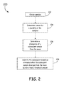
- Figure 2 is flow chart illustrating one embodiment of a method for identifying erroneous sensor outputs
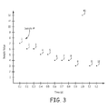
- Figure 3 is a timing diagram illustrating one embodiment of a plurality of samples from a sensor.
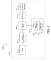
- Figure 4 is a block diagram of one embodiment of a system for identifying erroneous sensor outputs.
- Erroneous outputs are identified by comparing output data to a mean of a portion of the previous output data.
- a sliding window is used to select the previous output data from which the mean is determined. For example, in one embodiment, as output data is obtained from the sensor, a currently obtained output data is compared to the mean of the immediately preceding output data. If the current output data diverges from the mean by more than a threshold, the current output data is identified as erroneous. If the current output data diverges by less than or equal to the threshold, the output data is likely valid and is not identified as erroneous. Divergence between the output data and a threshold, as well as determination of a threshold is discussed in more detail below.
- the output data from the sensor is then sent to a controller which uses the data to control a mechanism. Either in the controller or in processing prior to the controller, the erroneousness of the data is taken into account. For example, in one embodiment, once output data is identified as erroneous, the output data may be discarded such that the erroneous output data is not used in further processing of the data. In other embodiments, other actions (discussed in more detail below) may be taken to account for the erroneous output data.
- FIG. 1 illustrates one embodiment of a system 100 for identifying an erroneous sensor output.
- System 100 includes a sensor 102 communicatively coupled to an analog to digital converter (ADC) 106 which is communicatively coupled to a processing device 104.
- ADC analog to digital converter
- Processing device is coupled to an associated memory 108 housing program code 110 for identifying erroneous sensor outputs.
- Sensor 102 obtains measurements from the surrounding environment and outputs data to processing device 104.
- Processing device 104 analyzes the data according to instructions provided by program code 110 to identify erroneous data from sensor 102.
- sensor 102 is an analog sensor that outputs a voltage that is relative to the measurement obtained by sensor 102.
- ADC 106 converts the analog voltage into digital samples and sends the digital samples to processing device 104.
- sensor 102 is a digital sensor which directly outputs digital samples to processing device 104.
- Processing device 104 receives samples obtained by sensor 102 and identifies erroneous samples.
- Figure 2 illustrates one embodiment of a method 200 for identifying erroneous samples.
- processing device 104 compares each sample to a mean of a plurality of samples obtained by sensor 102 previous in time to the time in which sensor 102 obtained the sample being compared.
- the data within the samples is obtained by sensor 102.
- the data within samples comprises measurements obtained by sensor 102 of the environment around sensor 102. These measurements are output as digital samples to processing device 104 either directly by sensor 102 or through ADC 106 as mentioned above (202).
- sensor 102 continually obtains data and samples are continually provided to processing system 104. In one embodiment, samples are provided to processing system 104 every 1/10 of a second. For each sample, processing system 104 determines a mean of a portion of the previously obtained samples (204). Processing system 104 then compares the mean to the current sample to determine a divergence of the current sample from the mean (206).
- processing system 104 When the divergence of the current sample from the mean is greater than a threshold divergence, processing system 104 identifies the current sample as erroneous (208). When the current sample is less than or equal to the threshold divergence, processing system 104 does not identify the current sample as erroneous.
- the threshold is selected based on empirical data.
- the threshold is selected high enough to ensure that a sufficiently low number of accurate samples are incorrectly identified as erroneous.
- the threshold is selected low enough to ensure that a sufficiently high number of actual erroneous samples are identified as erroneous.
- the divergence between a sample and the mean is calculated as a coefficient of variance of the sample relative to the mean.
- the coefficient of variance is a dimensionless measure of the relative variability of the sample, designed to allow comparisons of variation for samples with different average sizes.
- the coefficient of variance is calculated by taking the standard deviation over 'n' samples, normalized by the mean of those 'n' samples.
- the threshold is a selected coefficient of variance that is determined from empirical data. In one embodiment, the coefficient of variance is selected as 5. In another embodiment, a simple difference between the sample and the mean is used as the threshold.
- Figure 3 illustrates one example of a timing diagram illustrating a plurality of samples that are processed as described in method 200.
- sample 10 is being analyzed by processing device 104 to determine if the sample is erroneous.
- processing device 104 compares sample 10 to the mean of the three samples that immediately precede sample 10 in time.
- processing device 104 determines the mean of samples 7, 8, and 9.
- samples 7, 8, and 9 represent values 4, 4, and 3 respectively.
- the means of samples 7, 8, and 9 is 3 2/3.
- sample 10 is compared to the mean to determine a divergence of sample 10 from the mean. This divergence from the mean is compared to a threshold divergence to determine whether sample 10 is an erroneous sample.
- each sample received from sensor 102 is analyzed to determine whether the sample is erroneous.
- processing device 104 determines a mean based on a plurality of samples in a sliding window. For example, referring back to Figure 3 , assuming as described above, processing system 104 has completed analyzing sample 10, and processing system 104 uses a sliding window to determine from which samples the mean is determined. During processing of sample 10, the sliding window contains samples 7, 8, and 9. After sample 10 is analyzed as described above, sample 11 is received and analyzed by processing device 104. For sample 11 the sliding window "slides" from including samples 7, 8, and 9 used for sample 10 to including samples 8, 9, and 10.
- Processing device 104 determines the mean from samples 8, 9, and 10 and compares sample 11 to this mean. The divergence of sample 11 from this mean is then compared to the threshold to determine whether sample 11 contains erroneous data. Continuing with this example, processing device 104 analyzes each sample in this way such that each sample is compared to the mean of three samples immediately previous in time.
- processing device 104 does not analyze samples during startup of sensor 102. This is because the first samples have no previous samples from which to obtain a mean and/or sensor 102 may be going through an initialization procedure.
- each erroneous sample is flagged by processing device 104. Flagging the erroneous samples enables the samples to be discarded or otherwise processed differently than non-erroneous samples during further processing. For example, flagged samples may be given less weight during further processing than un-flagged samples.
- the sample is discarded. Here, for example, the sample is replaced with a sample equal to the mean of the previous samples.
- a sample identified as erroneous is discarded for further processing except for calculation of a mean for the erroneous determination of subsequent samples. Thus, the sample is used in the sliding window to determine a mean for successive samples, but the sample is not used in any further processing of the samples.
- each erroneous sample is replaced.
- a sample and hold algorithm is used to replace an erroneous sample with the last valid (non-erroneous) sample obtained.
- the erroneous sample is replaced with a predicted value based on a slope of the previous n valid samples obtained.
- identification of erroneous samples from sensor 102 is performed on the raw data output from sensor 102.
- the data output from sensor 102 has not been filtered or otherwise altered prior to analyzing by processing device 104.
- the samples are analyzed by processing system 104 in real time, such that data is output from sensor 102 and a sample is received by processing system 104, processing system 104 analyzes the data as the data is received.
- the samples are provided to a controller (not shown) for controlling the operation of a mechanism.
- the controller causes the mechanism to make a physical movement based on the data received within the samples.
- processing system 104 has discarded all erroneous data, thus the commands from controller and the actions of the mechanism are based only on non-erroneous data.
- the erroneous data is given less weight, thus controller may provide a different command to move mechanism based on an erroneous data point as compared to the same value in a non-erroneous data point.
- the mechanism is a thruster for an aircraft.
- the mechanism is a brake for a wheeled vehicle.
- the mechanism is a flap for an aircraft.
- the mean is selected based on system and application criteria. For example, when sensor 102 is used in a setting in which the physical quantity that is measured by sensor 102 varies rapidly, it may be advantageous to use a lower number of samples to calculate the mean. This is because when the samples vary rapidly, a larger number of samples may include samples from when the sensor was measuring a different physical quantity and thus, the mean may not reflect the actual mean of the more current measurements.
- sensor 102 when sensor 102 is used in a situation in which the physical quantity that is measured by sensor 102 does not vary rapidly, it may be advantageous to use a higher number of samples to calculate the mean. This is because a larger number of samples may provide a more accurate mean.
- samples used to determine the mean are the samples immediately preceding in time the sample being compared, in other embodiments, earlier preceding samples are used. For example, in one embodiment, when determining whether sample 10 is erroneous, samples 5, 6, and 7 are used to determine the mean. Furthermore, although as described above, the samples used to determine the mean are consecutive in time, in other embodiments, non-consecutive samples are used to determine a mean.
- System 400 includes a sensor 402, a sample and hold circuit 406, a processing device 404, a memory 408, and program code 410 which as substantially similar to those described with respect to Figure 1 .
- System 400 also includes program code for a digital filter 412, a controller 414, and an aircraft landing mechanism 416.
- system 400 is installed in an aircraft 418 and used to assist in landing aircraft 418.
- sensor 402 is an acoustic proximity sensor and is mounted on aircraft 418 and used to determine a distance from aircraft 418 to the ground.
- the samples after being processed to determine whether they are erroneous are used by an aircraft control system 414 to control aircraft landing mechanism 416 in order to assist in landing aircraft 418.
- sensor 402 is an acoustic sensor which transmits acoustic pulses and detects return echo pulses from the transmitted pulses.
- the acoustic sensor measures an amount of time passed from when the acoustic pulse was transmitted until when a return pulse is received.
- the acoustic sensor then outputs a voltage level representing this time measurement. For example, in one embodiment, a time measurement of 5 microseconds results in an output of 3 volts, and a time measurement of 10 microseconds results in an output of 4 volts. This time measurement is provided (possibly after conversion by a sample and hold circuit) as a digital sample to processing system 404.
- processing system 404 receives samples on a periodic basis, for example, one sample every 1/10 of a second.
- the samples are further processed depending upon the application of sensor 402.
- the samples are further processed by being filtered by digital filter 412.
- digital filter 412 include a simple averaging type filter and a more sophisticated Kalman type filter.
- Digital filter 412 smoothes the sampled data to provide a more realistic portrayal of the actual value being sensed.
- the digitally filtered data is then used by controller 414 to control aircraft landing mechanism 416.
- the further processing is performed by processing device 104, in another embodiment, the further processing is performed by a separate processing device or devices (not shown). Examples of digital filters 412 and controller 414 to control aircraft landing mechanisms are provided in U.S. Patent Application Serial No. 12/332,481 filed on December 11, 2008 and owned by the present assignee.
- processing device 404 performs multiple functions in addition to identifying erroneous data from sensor 402.
- the function of identifying erroneous samples, along with the other functions of processing device 404, are carried out by software operating on processing device 404.
- processing device 404 comprises a general purpose processor coupled to a memory device containing the software that operates on the processor.
- processing device 404 is a microprocessor that is programmed solely to identify erroneous samples from sensor 402.
- method 200 is implemented in processor readable instructions, such as program modules or applications, which are executed by processing device.
- program modules or applications include routines, programs, objects, data components, data structures, algorithms, and the like, which perform particular tasks or implement particular abstract data types. These represent examples of program code for executing steps of the methods disclosed herein. The particular sequence of such executable instructions or associated data structures represent examples of corresponding acts for implementing the functions described in such steps.
- identifying erroneous data improves the accuracy of subsequently processed data by taking into account the erroneous data during subsequent processing.
- using a sliding window enables the threshold to take into account changes in the sensor outputs.
- the threshold is based on a divergence from the mean. Since the mean is not locked at a single value, and is instead determined based on a temporally varying plurality of the preceding samples, the mean takes into account changes in the sample data. This is because the mean is based on only the samples within the window. Older samples taken when the sensor may have been measuring a different physical quantity are automatically factored out of the mean calculation by the sliding window.
- identifying erroneous sensor outputs based on a mean of preceding samples does not introduce lag into the sample stream from the sensor, because the decision of whether the output is erroneous relies only on previously obtained data, not on future data.
- instructions for carrying out the various process tasks, and calculations other data used in the operation of the methods described above are implemented in a program product including software, firmware, or other processor readable instructions. These instructions are stored on any appropriate processor readable medium used for storage of processor readable instructions or data structures. Such processor readable media is any available media that can be accessed by a general purpose or special purpose computer or processor, or any programmable logic device.
- Suitable processor readable media comprises, for example, non-volatile memory devices including semiconductor memory devices such as erasable programmable read-only memory (EPROM), electrically erasable programmable read-only memory (EEPROM_, or flash memory devices; magnetic disks such as internal hard disks or removable disks; magneto-optical disks; compact discs (CDs), digital versatile (or video) discs (DVDs), or other optical storage disks; nonvolatile read only memory (ROM), random access memory (RAM), and other like media; or any other media that can be used to carry or store desired program code in the form of processor executable instructions or data structures.
- semiconductor memory devices such as erasable programmable read-only memory (EPROM), electrically erasable programmable read-only memory (EEPROM_, or flash memory devices
- magnetic disks such as internal hard disks or removable disks
- magneto-optical disks compact discs (CDs), digital versatile (or video) discs (DVDs), or other optical storage disks
- processors may be supplemented by, or incorporated in, specially-designed Application Specific Integrated Circuits (ASICs) or Field Programmable Gate Arrays (FPGAs).
- ASICs Application Specific Integrated Circuits
- FPGAs Field Programmable Gate Arrays
Landscapes
- Physics & Mathematics (AREA)
- General Physics & Mathematics (AREA)
- Measurement Of Velocity Or Position Using Acoustic Or Ultrasonic Waves (AREA)
- Transmission And Conversion Of Sensor Element Output (AREA)
- Radar Systems Or Details Thereof (AREA)
Applications Claiming Priority (1)
| Application Number | Priority Date | Filing Date | Title |
|---|---|---|---|
| US12/398,041 US8359178B2 (en) | 2009-03-04 | 2009-03-04 | Method and apparatus for identifying erroneous sensor outputs |
Publications (1)
| Publication Number | Publication Date |
|---|---|
| EP2226695A1 true EP2226695A1 (de) | 2010-09-08 |
Family
ID=42236495
Family Applications (1)
| Application Number | Title | Priority Date | Filing Date |
|---|---|---|---|
| EP09179539A Withdrawn EP2226695A1 (de) | 2009-03-04 | 2009-12-16 | Verfahren und Vorrichtung zur Identifizierung fehlerhafter Sensorausgaben |
Country Status (3)
| Country | Link |
|---|---|
| US (1) | US8359178B2 (de) |
| EP (1) | EP2226695A1 (de) |
| JP (1) | JP5607347B2 (de) |
Families Citing this family (8)
| Publication number | Priority date | Publication date | Assignee | Title |
|---|---|---|---|---|
| US9075446B2 (en) * | 2010-03-15 | 2015-07-07 | Qualcomm Incorporated | Method and apparatus for processing and reconstructing data |
| JP5890087B2 (ja) * | 2010-05-06 | 2016-03-22 | 古野電気株式会社 | 探知装置 |
| JP2012256821A (ja) | 2010-09-13 | 2012-12-27 | Semiconductor Energy Lab Co Ltd | 記憶装置 |
| US9162642B2 (en) * | 2012-10-05 | 2015-10-20 | Ford Global Technologies | Method and system for determining a primary direction of force resulting from a vehicle collision |
| AU2013357019B2 (en) * | 2012-12-14 | 2018-02-15 | Bae Systems Plc | Mitigation of anomalous propagation effects in radar |
| JP6362768B2 (ja) * | 2015-03-27 | 2018-07-25 | 三菱電機株式会社 | 端末装置 |
| US10082787B2 (en) | 2015-08-28 | 2018-09-25 | International Business Machines Corporation | Estimation of abnormal sensors |
| US10830899B2 (en) * | 2018-09-26 | 2020-11-10 | Bae Systems Information And Electronic Systems Integration Inc. | Visual display system for use in testing or monitoring a GPS enabled device |
Citations (6)
| Publication number | Priority date | Publication date | Assignee | Title |
|---|---|---|---|---|
| US20020065628A1 (en) * | 1999-11-04 | 2002-05-30 | Mcmahan David M. | Automated methods and systems for analyzing data associated with an industrial process |
| US20030154052A1 (en) | 2001-08-31 | 2003-08-14 | Shuichi Samata | Method for diagnosing life of manufacturing equipment using rotary machine |
| US7275425B2 (en) * | 2002-10-23 | 2007-10-02 | Robert Bosch Gmbh | Method for testing at least three sensors, which detect a measurable variable for an internal combustion engine |
| US20080082294A1 (en) * | 2006-09-28 | 2008-04-03 | Fisher-Rosemont Systems, Inc. | Method and system for detecting abnormal operation in a stirred vessel |
| US20080181280A1 (en) | 2007-01-31 | 2008-07-31 | Wang Wei D | Method and apparatus to monitor a temperature sensing device |
| EP2296272A2 (de) * | 2009-09-14 | 2011-03-16 | Soonhan Engineering Corp. | Verfahren zum Erkennen und Filtern eines Rauschstörungssignals |
Family Cites Families (47)
| Publication number | Priority date | Publication date | Assignee | Title |
|---|---|---|---|---|
| JPS5951875B2 (ja) * | 1980-05-28 | 1984-12-17 | 東洋製罐株式会社 | 不良空缶自動弁別除去方法および装置 |
| JPS59500391A (ja) * | 1982-05-17 | 1984-03-08 | インタ−ナシヨナル・ビジネス・マシ−ンズ・コ−ポレ−シヨン | セクタ.サ−ボ探索制御装置 |
| US4606316A (en) * | 1982-05-24 | 1986-08-19 | Mitsubishi Denki Kabushiki Kaisha | Ignition timing control system for internal combustion engine |
| US4518917A (en) * | 1982-08-31 | 1985-05-21 | Westinghouse Electric Corp. | Plural sensor apparatus for monitoring turbine blading with undesired component elimination |
| US4712427A (en) * | 1985-10-21 | 1987-12-15 | Sundstrand Data Control, Inc. | Vibrating beam accelerometer with velocity change output |
| JP2525372B2 (ja) | 1986-08-15 | 1996-08-21 | 富士通テン株式会社 | アンチスキツド制御装置 |
| JPH0792377B2 (ja) * | 1987-05-29 | 1995-10-09 | 住友金属工業株式会社 | 厚み計測装置 |
| US5136512A (en) * | 1988-06-26 | 1992-08-04 | Cubic Defense Systems, Inc. | Ground collision avoidance system |
| DE3841089A1 (de) * | 1988-12-07 | 1990-06-13 | Bosch Gmbh Robert | Verfahren zur auswertung eines sensorsignals |
| US5049838A (en) * | 1989-09-19 | 1991-09-17 | The Boeing Company | Minimum intrusion search oscillator for use in feedback loops |
| US5267277A (en) * | 1989-11-02 | 1993-11-30 | Combustion Engineering, Inc. | Indicator system for advanced nuclear plant control complex |
| US5175438A (en) * | 1989-11-10 | 1992-12-29 | Nikuni Machinery Industrial Co., Ltd. | Method of distinguishing particles in fluid and apparatus for the same using dual wavelength reflectivity ratio sensing |
| JP3267310B2 (ja) | 1991-07-10 | 2002-03-18 | パイオニア株式会社 | Gpsナビゲーション装置 |
| JP2687066B2 (ja) * | 1992-04-13 | 1997-12-08 | トヨタ自動車株式会社 | ドップラ式対地車速検出装置 |
| US5479161A (en) * | 1994-03-25 | 1995-12-26 | Honeywell Inc. | Automatic calibration of redundant sensors |
| US5621776A (en) * | 1995-07-14 | 1997-04-15 | General Electric Company | Fault-tolerant reactor protection system |
| US6029111A (en) * | 1995-12-28 | 2000-02-22 | Magellan Dis, Inc. | Vehicle navigation system and method using GPS velocities |
| US5923286A (en) * | 1996-10-23 | 1999-07-13 | Honeywell Inc. | GPS/IRS global position determination method and apparatus with integrity loss provisions |
| US5906655A (en) * | 1997-04-02 | 1999-05-25 | Caterpillar Inc. | Method for monitoring integrity of an integrated GPS and INU system |
| JP3610234B2 (ja) * | 1998-07-17 | 2005-01-12 | 株式会社メディア・テクノロジー | アイリス情報取得装置およびアイリス識別装置 |
| US6108269A (en) * | 1998-10-01 | 2000-08-22 | Garmin Corporation | Method for elimination of passive noise interference in sonar |
| US6201763B1 (en) * | 1999-09-20 | 2001-03-13 | The United States Of America As Represented By The Secretary Of The Navy | Depthimeter |
| JP4562051B2 (ja) * | 1999-11-30 | 2010-10-13 | 独立行政法人産業技術総合研究所 | 損耗センサ付き切削工具の信号処理装置および信号処理方法 |
| US6678394B1 (en) * | 1999-11-30 | 2004-01-13 | Cognex Technology And Investment Corporation | Obstacle detection system |
| US6335905B1 (en) * | 1999-12-17 | 2002-01-01 | Garmin Corporation | Method for elimination of passive noise interference in sonar |
| JP4229358B2 (ja) * | 2001-01-22 | 2009-02-25 | 株式会社小松製作所 | 無人車両の走行制御装置 |
| JP2002339178A (ja) * | 2001-05-15 | 2002-11-27 | Murata Mach Ltd | 仮撚機 |
| FR2832796B1 (fr) * | 2001-11-27 | 2004-01-23 | Thales Sa | Centrale de navigation inertielle hybride a integrite amelioree en altitude |
| US6793174B2 (en) * | 2002-09-16 | 2004-09-21 | The Boeing Company | Pulsejet augmentor powered VTOL aircraft |
| US7274387B2 (en) * | 2002-10-15 | 2007-09-25 | Digicomp Research Corporation | Automatic intrusion detection system for perimeter defense |
| JP2004271233A (ja) * | 2003-03-05 | 2004-09-30 | Fujitsu Ten Ltd | 異常検出機能を備えたレーダ装置 |
| US7343232B2 (en) * | 2003-06-20 | 2008-03-11 | Geneva Aerospace | Vehicle control system including related methods and components |
| US20050040985A1 (en) * | 2003-08-19 | 2005-02-24 | Trammell Hudson | System and method for providing improved accuracy relative positioning from a lower end GPS receiver |
| US7204123B2 (en) * | 2004-03-26 | 2007-04-17 | Honeywell International Inc. | Accuracy enhancement of a sensor during an anomalous event |
| US7126496B2 (en) * | 2004-09-30 | 2006-10-24 | Safe Flight Instrument Corporation | Tactile cueing system and method for aiding a helicopter pilot in making landings |
| US7219856B2 (en) * | 2005-02-04 | 2007-05-22 | Lockheed Martin Corporation | UAV recovery system |
| US20060229534A1 (en) * | 2005-03-29 | 2006-10-12 | Chang Walter H | System and method for measuring coefficient variance of resonance frequency of musculoskeletal system |
| EP1866716B1 (de) * | 2005-04-04 | 2011-06-29 | Fisher-Rosemount Systems, Inc. | Diagnose eines prozessregelungssystems |
| CA2605177C (en) * | 2005-04-19 | 2011-06-21 | Jaymart Sensors, Llc | Miniaturized inertial measurement unit and associated methods |
| IL169269A (en) | 2005-06-19 | 2012-08-30 | Israel Aerospace Ind Ltd | Method for automatic navigation of an unmanned vehicle Carrying data that can be read by a computer and storing a program to perform the method |
| US7962252B2 (en) * | 2005-06-20 | 2011-06-14 | The United States Of America As Represented By The Administrator Of The National Aeronautics And Space Administration | Self-contained avionics sensing and flight control system for small unmanned aerial vehicle |
| WO2007124014A2 (en) | 2006-04-19 | 2007-11-01 | Swope John M | System for position and velocity sense and control of an aircraft |
| US7702460B2 (en) * | 2006-06-17 | 2010-04-20 | Northrop Grumman Guidance And Electronics Company, Inc. | Estimate of relative position between navigation units |
| US7388809B2 (en) * | 2006-09-28 | 2008-06-17 | Furuno Electric Company, Limited | Fish finder that transmits ultrasonic waves, receives echo signals, and performs interference removal |
| US20080195304A1 (en) * | 2007-02-12 | 2008-08-14 | Honeywell International Inc. | Sensor fusion for navigation |
| US7463340B2 (en) * | 2007-03-28 | 2008-12-09 | Honeywell International Inc. | Ladar-based motion estimation for navigation |
| US20100152933A1 (en) * | 2008-12-11 | 2010-06-17 | Honeywell International Inc. | Apparatus and method for unmanned aerial vehicle ground proximity detection, landing and descent |
-
2009
- 2009-03-04 US US12/398,041 patent/US8359178B2/en not_active Expired - Fee Related
- 2009-12-16 EP EP09179539A patent/EP2226695A1/de not_active Withdrawn
- 2009-12-18 JP JP2009287464A patent/JP5607347B2/ja not_active Expired - Fee Related
Patent Citations (6)
| Publication number | Priority date | Publication date | Assignee | Title |
|---|---|---|---|---|
| US20020065628A1 (en) * | 1999-11-04 | 2002-05-30 | Mcmahan David M. | Automated methods and systems for analyzing data associated with an industrial process |
| US20030154052A1 (en) | 2001-08-31 | 2003-08-14 | Shuichi Samata | Method for diagnosing life of manufacturing equipment using rotary machine |
| US7275425B2 (en) * | 2002-10-23 | 2007-10-02 | Robert Bosch Gmbh | Method for testing at least three sensors, which detect a measurable variable for an internal combustion engine |
| US20080082294A1 (en) * | 2006-09-28 | 2008-04-03 | Fisher-Rosemont Systems, Inc. | Method and system for detecting abnormal operation in a stirred vessel |
| US20080181280A1 (en) | 2007-01-31 | 2008-07-31 | Wang Wei D | Method and apparatus to monitor a temperature sensing device |
| EP2296272A2 (de) * | 2009-09-14 | 2011-03-16 | Soonhan Engineering Corp. | Verfahren zum Erkennen und Filtern eines Rauschstörungssignals |
Non-Patent Citations (2)
| Title |
|---|
| SABYASACHI BASU ET AL: "Automatic outlier detection for time series: an application to sensor data", 22 August 2006, KNOWLEDGE AND INFORMATION SYSTEMS ; AN INTERNATIONAL JOURNAL, SPRINGER-VERLAG, LO, PAGE(S) 137 - 154, ISSN: 0219-3116, XP019475923 * |
| SABYASACHI BASU ET AL: "Automatic outlier detection for time series: an application to sensor data", KNOWLEDGE AND INFORMATION SYSTEMS ; AN INTERNATIONAL JOURNAL, SPRINGER-VERLAG, LO, vol. 11, no. 2, 22 August 2006 (2006-08-22), pages 137 - 154, XP019475923, ISSN: 0219-3116 * |
Also Published As
| Publication number | Publication date |
|---|---|
| US20100228512A1 (en) | 2010-09-09 |
| JP2010204090A (ja) | 2010-09-16 |
| JP5607347B2 (ja) | 2014-10-15 |
| US8359178B2 (en) | 2013-01-22 |
Similar Documents
| Publication | Publication Date | Title |
|---|---|---|
| EP2226695A1 (de) | Verfahren und Vorrichtung zur Identifizierung fehlerhafter Sensorausgaben | |
| US11465643B2 (en) | Obstacle recognition device and obstacle recognition method | |
| US11415690B2 (en) | Method and system comparing odometer velocity to radar based velocity | |
| JP5551169B2 (ja) | 全てディジタルの見通し線(los)プロセッサアーキテクチャ | |
| CN104736973B (zh) | 用于确定马达驱动的致动部件的位置的方法和装置 | |
| CN108761408B (zh) | 一种评估地基天气雷达非降水回波识别算法效果的方法 | |
| CA2742418C (en) | Method and apparatus for passive determination of target data | |
| US6556511B1 (en) | Method of locking onto and tracking a target | |
| CN109696665B (zh) | 超声波传感器测量数据的处理方法、装置及设备 | |
| CN111971581A (zh) | 用于验证由雨量传感器提供的数据的设备、方法和计算机程序产品 | |
| US10605607B2 (en) | Two step pruning in a PHD filter | |
| US7576685B2 (en) | Radar sensor | |
| EP2251819A1 (de) | Objektklassifizierung mit Partikel-Filtern | |
| KR102196479B1 (ko) | 반능동 레이저 신호를 탐지하여 표적을 추적하는 장치 및 방법 | |
| Belinska et al. | Application of least square method with variable parameters for GPS accuracy improvement | |
| JP5512987B2 (ja) | 車両用レーダ装置 | |
| US20070185634A1 (en) | Method and system for controlling a driver-assistance device | |
| KR102077461B1 (ko) | 반능동 레이저 신호를 탐지하는 장치, 방법 및 시스템 | |
| JP6342270B2 (ja) | 目標検出装置、目標検出方法及び目標検出プログラム | |
| CN114482754B (zh) | 车辆后备箱开启方法、装置、车辆及存储介质 | |
| US11086012B2 (en) | Method and system for recognizing objects using ultrasonic signals | |
| WO2023213417A1 (en) | Time-series anomaly detection | |
| RU2394264C2 (ru) | Устройство для управления полетом над водной поверхностью (варианты) | |
| CN116106893A (zh) | 机动目标跟踪方法、装置、设备及存储介质 | |
| JP2009030998A (ja) | 距離算出装置 |
Legal Events
| Date | Code | Title | Description |
|---|---|---|---|
| PUAI | Public reference made under article 153(3) epc to a published international application that has entered the european phase |
Free format text: ORIGINAL CODE: 0009012 |
|
| 17P | Request for examination filed |
Effective date: 20091216 |
|
| AK | Designated contracting states |
Kind code of ref document: A1 Designated state(s): AT BE BG CH CY CZ DE DK EE ES FI FR GB GR HR HU IE IS IT LI LT LU LV MC MK MT NL NO PL PT RO SE SI SK SM TR |
|
| AX | Request for extension of the european patent |
Extension state: AL BA RS |
|
| 17Q | First examination report despatched |
Effective date: 20100816 |
|
| RAP1 | Party data changed (applicant data changed or rights of an application transferred) |
Owner name: HONEYWELL INTERNATIONAL INC. |
|
| STAA | Information on the status of an ep patent application or granted ep patent |
Free format text: STATUS: THE APPLICATION IS DEEMED TO BE WITHDRAWN |
|
| 18D | Application deemed to be withdrawn |
Effective date: 20160701 |