EP2226503A1 - Kolbenverdichter - Google Patents
Kolbenverdichter Download PDFInfo
- Publication number
- EP2226503A1 EP2226503A1 EP10001437A EP10001437A EP2226503A1 EP 2226503 A1 EP2226503 A1 EP 2226503A1 EP 10001437 A EP10001437 A EP 10001437A EP 10001437 A EP10001437 A EP 10001437A EP 2226503 A1 EP2226503 A1 EP 2226503A1
- Authority
- EP
- European Patent Office
- Prior art keywords
- stage
- annular gap
- cylinder
- compressor
- cylinders
- Prior art date
- Legal status (The legal status is an assumption and is not a legal conclusion. Google has not performed a legal analysis and makes no representation as to the accuracy of the status listed.)
- Withdrawn
Links
- 239000002826 coolant Substances 0.000 claims abstract description 9
- XAGFODPZIPBFFR-UHFFFAOYSA-N aluminium Chemical compound [Al] XAGFODPZIPBFFR-UHFFFAOYSA-N 0.000 claims abstract description 7
- 229910052782 aluminium Inorganic materials 0.000 claims abstract description 7
- 229910001060 Gray iron Inorganic materials 0.000 claims abstract description 5
- 239000003562 lightweight material Substances 0.000 claims abstract description 4
- 239000000463 material Substances 0.000 claims abstract description 4
- 238000001816 cooling Methods 0.000 description 8
- 230000006835 compression Effects 0.000 description 5
- 238000007906 compression Methods 0.000 description 5
- 239000004411 aluminium Substances 0.000 description 1
- 238000010276 construction Methods 0.000 description 1
- 239000000498 cooling water Substances 0.000 description 1
- 210000003746 feather Anatomy 0.000 description 1
- 238000004519 manufacturing process Methods 0.000 description 1
- 239000003507 refrigerant Substances 0.000 description 1
- 238000009423 ventilation Methods 0.000 description 1
- XLYOFNOQVPJJNP-UHFFFAOYSA-N water Substances O XLYOFNOQVPJJNP-UHFFFAOYSA-N 0.000 description 1
Images
Classifications
-
- F—MECHANICAL ENGINEERING; LIGHTING; HEATING; WEAPONS; BLASTING
- F04—POSITIVE - DISPLACEMENT MACHINES FOR LIQUIDS; PUMPS FOR LIQUIDS OR ELASTIC FLUIDS
- F04B—POSITIVE-DISPLACEMENT MACHINES FOR LIQUIDS; PUMPS
- F04B39/00—Component parts, details, or accessories, of pumps or pumping systems specially adapted for elastic fluids, not otherwise provided for in, or of interest apart from, groups F04B25/00 - F04B37/00
- F04B39/06—Cooling; Heating; Prevention of freezing
- F04B39/064—Cooling by a cooling jacket in the pump casing
-
- F—MECHANICAL ENGINEERING; LIGHTING; HEATING; WEAPONS; BLASTING
- F04—POSITIVE - DISPLACEMENT MACHINES FOR LIQUIDS; PUMPS FOR LIQUIDS OR ELASTIC FLUIDS
- F04B—POSITIVE-DISPLACEMENT MACHINES FOR LIQUIDS; PUMPS
- F04B27/00—Multi-cylinder pumps specially adapted for elastic fluids and characterised by number or arrangement of cylinders
- F04B27/005—Multi-cylinder pumps specially adapted for elastic fluids and characterised by number or arrangement of cylinders with two cylinders
-
- F—MECHANICAL ENGINEERING; LIGHTING; HEATING; WEAPONS; BLASTING
- F04—POSITIVE - DISPLACEMENT MACHINES FOR LIQUIDS; PUMPS FOR LIQUIDS OR ELASTIC FLUIDS
- F04B—POSITIVE-DISPLACEMENT MACHINES FOR LIQUIDS; PUMPS
- F04B39/00—Component parts, details, or accessories, of pumps or pumping systems specially adapted for elastic fluids, not otherwise provided for in, or of interest apart from, groups F04B25/00 - F04B37/00
- F04B39/12—Casings; Cylinders; Cylinder heads; Fluid connections
- F04B39/122—Cylinder block
-
- F—MECHANICAL ENGINEERING; LIGHTING; HEATING; WEAPONS; BLASTING
- F04—POSITIVE - DISPLACEMENT MACHINES FOR LIQUIDS; PUMPS FOR LIQUIDS OR ELASTIC FLUIDS
- F04B—POSITIVE-DISPLACEMENT MACHINES FOR LIQUIDS; PUMPS
- F04B41/00—Pumping installations or systems specially adapted for elastic fluids
- F04B41/06—Combinations of two or more pumps
-
- F—MECHANICAL ENGINEERING; LIGHTING; HEATING; WEAPONS; BLASTING
- F04—POSITIVE - DISPLACEMENT MACHINES FOR LIQUIDS; PUMPS FOR LIQUIDS OR ELASTIC FLUIDS
- F04B—POSITIVE-DISPLACEMENT MACHINES FOR LIQUIDS; PUMPS
- F04B53/00—Component parts, details or accessories not provided for in, or of interest apart from, groups F04B1/00 - F04B23/00 or F04B39/00 - F04B47/00
- F04B53/08—Cooling; Heating; Preventing freezing
-
- F—MECHANICAL ENGINEERING; LIGHTING; HEATING; WEAPONS; BLASTING
- F16—ENGINEERING ELEMENTS AND UNITS; GENERAL MEASURES FOR PRODUCING AND MAINTAINING EFFECTIVE FUNCTIONING OF MACHINES OR INSTALLATIONS; THERMAL INSULATION IN GENERAL
- F16J—PISTONS; CYLINDERS; SEALINGS
- F16J10/00—Engine or like cylinders; Features of hollow, e.g. cylindrical, bodies in general
- F16J10/02—Cylinders designed to receive moving pistons or plungers
Definitions
- the invention relates to a reciprocating compressor for compressing a gas, in particular of air. This involves two- or multi-stage compressors.
- the invention relates to compressors for vehicles, also called air compressor.
- a compressor of the type in question comprises two or more cylinders.
- the cylinders are connected in series. Accordingly, the medium to be compressed is first compressed to a first value. It is then fed to the second cylinder and compressed to a second, even higher value.
- the temperature of the pressure medium on entering the cylinder increases from a low value of, for example, 20 ° C to re-emerge after compression with, for example, 200 ° C. Therefore, cooling is required.
- a cooling device is provided between the two pressure stages.
- the cylinders must have the necessary strength to be able to absorb, above all, the normal forces of the piston. They should be easy at the same time, which is increasingly required especially for use for motor vehicles. The cooling should be optimal. Finally, the compressor should be simple in construction and inexpensive to manufacture.
- the invention has for its object to provide a particular multi-stage compressor, which meets the requirements. He should thus comply with the requirements in terms of strength, structure, volume and cooling.
- At least one of the cylinders has an inner bushing and an outer bushing, between which an annular gap for passing a cooling medium remains.
- This embodiment of the invention is based on the following consideration: In a particularly two-stage compressor, the temperatures of the compressed medium are above the temperatures of the cooling medium only in the last stage. Therefore, only the last cylinder in the compression direction is double-walled with an annular gap for the cooling medium designed by having an inner liner and an outer sleeve.
- Double-walled but uncooled cylinders are known in refrigerant compressors.
- the two cylinder liners are close together.
- both of these types of machines each represent a different genus than the air compressors discussed here, and are therefore not comparable with this.
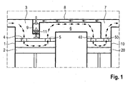
- the figure illustrates in schematic representation a two-stage air compressor.
- the air compressor comprises a first compressor stage with a cylinder 1 and a piston 2, and a second compressor stage with a cylinder 10 and a piston 20.
- the air is sucked from the piston 2 of the first stage of a suction chamber 3. It enters through a suction valve 4 in the cylinder 1 a. After its compression, it passes through a pressure valve 5 in an intermediate chamber 6 with a cooler, not shown.
- the air then passes through another suction valve 40 in the cylinder 10 of the second compressor stage, and exits after compression by a pressure valve 50 from the cylinder 10, and reaches a pressure chamber. 7
- Air passes from the pressure chamber 7 via a branch line 8 to a discharge piston 9, which is acted upon by a spring 11 against the pressure of the air from the branch line 8.
- the housing of the air compressor is largely made of aluminum.
- the two cylinders 1 and 10 are double-walled, as illustrated by the second cylinder 10.
- the outer cylinder liner 10.1 of the second compressor stage is formed from the housing and thus made of aluminum.
- the inner cylinder liner 10.2 is made of gray cast iron.
- the inner cylinder liner In the first compressor stage, the inner cylinder liner is inserted into the outer cylinder liner virtually gap-free.
- annular gap 10.3 located at the second compressor stage between the outer cylinder liner 10.1 and the inner cylinder liner 10.2 an annular gap 10.3.
- the annular gap 10.3 may extend over part of the length of the cylinder 10, or over the entire cylinder length, or over the stroke of the piston 20 of the second compressor stage.
- annular gap 10.3 of the cylinder 10 of the second compressor stage is connected to a cooling medium which flows through the annular gap.
- the inlet and the outlet may be located at any points of the axial extent of the annular gap 10.3, for reasons of ventilation, the outlet should be in the top dead center.
- the pistons 2 and 20 of the two compressor stages are each assigned a connecting rod 2.1 or 20.1. These work on a crankshaft 12.
- the cooling device 13 is used for intermediate cooling of the coming of the first compressor stage gas, in the present embodiment, the air.
- the compressed air thus enters the second cylinder 10 already at a somewhat reduced temperature.
- a cooling medium which passes through the annular gap 10.3, causes a further cooling of the gas in the second compressor stage.
- the cooling medium will generally be water or cooling water of the engine.
Landscapes
- Engineering & Computer Science (AREA)
- General Engineering & Computer Science (AREA)
- Mechanical Engineering (AREA)
- Chemical & Material Sciences (AREA)
- Combustion & Propulsion (AREA)
- Compressor (AREA)
Abstract
Die Erfindung betrifft einen zwei- oder mehrstufigen Verdichter zum Verdichten eines Gases, umfassend die folgenden Bauteile beziehungsweise Merkmale:
- eine mindestens der Anzahl der Stufen entsprechende Zahl von Zylindern;
- wenigstens einer der Zylinder umfasst eine innere Laufbuchse aus einem standfesten Werkstoff wie Grauguss, und eine äußere Buchse aus einem leichten Werkstoff wie Aluminium;
- wenigstens einer der Zylinder weist einen Ringspalt zwischen der inneren Laufbuchse und der äußeren Buchse auf;
- der Ringspalt weist einen Einlass und einen Auslass für ein Kühlmedium auf
- eine mindestens der Anzahl der Stufen entsprechende Zahl von Zylindern;
- wenigstens einer der Zylinder umfasst eine innere Laufbuchse aus einem standfesten Werkstoff wie Grauguss, und eine äußere Buchse aus einem leichten Werkstoff wie Aluminium;
- wenigstens einer der Zylinder weist einen Ringspalt zwischen der inneren Laufbuchse und der äußeren Buchse auf;
- der Ringspalt weist einen Einlass und einen Auslass für ein Kühlmedium auf
Description
- Die Erfindung betrifft einen Kolbenverdichter zum Verdichten eines Gases, insbesondere von Luft. Dabei geht es um zwei- oder mehrstufige Verdichter. Die Erfindung betrifft Verdichter für Fahrzeuge, auch Luftpresser genannt.
- Ein Verdichter der in Rede stehenden Art umfasst zwei oder mehrere Zylinder. Die Zylinder sind in Reihe geschaltet. Demgemäß wird das zu verdichtende Medium zunächst auf einen ersten Wert verdichtet. Sodann wird es dem zweiten Zylinder zugeführt und auf einen zweiten, noch höheren Wert verdichtet. Beim Verdichten erhöht sich die Temperatur des Druckmediums beim Eintreten in den Zylinder von einem niedrigen Wert von zum Beispiel 20 °C, um nach dem Verdichten mit beispielsweise 200 °C wieder auszutreten. Daher ist eine Kühlung erforderlich. Zu diesem Zweck ist eine Kühleinrichtung zwischen die beiden Druckstufen vorgesehen.
- An Verdichter werden die folgenden Anforderungen gestellt: Die Zylinder müssen die notwendige Festigkeit aufweisen, um vor allem die Normalkräfte des Kolbens aufnehmen zu können. Sie sollen gleichzeitig leicht sein, was insbesondere bei Verwendung für Kraftfahrzeuge in zunehmendem Maße gefordert wird. Die Kühlung soll optimal sein. Schließlich soll der Verdichter einfach im Aufbau und kostengünstig in der Herstellung sein.
- Bei bekannten Verdichtern für Nutzfahrzeuge wurde die Gesamtheit dieser Anforderungen nicht erfüllt.
- Der Erfindung liegt die Aufgabe zugrunde, einen insbesondere mehrstufigen Verdichter anzugeben, der den Anforderungen entspricht. Er soll somit bezüglich Festigkeit, Aufbau, Bauvolumen und Kühlung den Anforderungen entsprechen.
- Diese Aufgabe wird durch die Merkmale von Anspruch 1 gelöst.
- Demgemäß weist wenigstens einer der Zylinder eine innere Laufbuchse sowie eine äußere Buchse auf, zwischen denen ein Ringspalt zum Hindurchschicken eines Kühlmediums verbleibt.
- Gemäß einer besonders vorteilhaften Ausführungsform der Erfindung weist ein insbesondere zweistufiger Verdichter die folgenden Merkmale auf:
- wenigstens der Zylinder der letzten Stufe umfasst eine innere Laufbuchse aus einem standfesten Werkstoff wie Grauguss, und eine äußere Buchse aus einem leichten Werkstoff wie Aluminium;
- wenigstens der Zylinder der letzten Stufe weist einen Ringspalt zwischen der inneren Laufbuchse und der äußeren Buchse auf;
- der Ringspalt weist einen Einlass und einen Auslass für ein Kühlmedium auf;
- die äußere Buchse kann aus dem Gehäuse des Luftpressers gebildet werden.
- Dieser Ausführungsform der Erfindung liegt die folgende Überlegung zugrunde: Bei einem insbesondere zweistufigen Verdichter liegen die Temperaturen des verdichteten Mediums erst in der letzten Stufe über den Temperaturen des Kühlmediums. Deswegen wird nur der in Verdichtungsrichtung letzte Zylinder doppelwandig mit einem Ringspalt für das Kühlmedium gestaltet, indem er eine innere Laufbuchse und eine äußere Buchse aufweist.
- Doppelwandige aber ungekühlte Zylinder sind bei Kältemittelkompressoren bekannt. Die beiden Zylinderbuchsen liegen dabei eng beieinander. Außerdem ist es bei befeuerten Motoren bekannt, den Zylinder doppelwandig auszuführen, mit einem gekühlten Ringspalt zwischen den beiden Zylinderbuchsen. Beide dieser Maschinenarten stellen jedoch jeweils eine andere Gattung als die hier behandelten Luftpresser dar, und sind daher mit diesem nicht zu vergleichen.
- Der Stand der Technik sowie die Erfindung sind anhand der Zeichnung näher erläutert. Darin ist im Einzelnen Folgendes dargestellt:
- Die Figur veranschaulicht in schematischer Darstellung einen zweistufigen Luftpresser.
- Der Luftpresser umfasst eine erste Verdichterstufe mit einem Zylinder 1 und einem Kolben 2, sowie eine zweite Verdichterstufe mit einem Zylinder 10 und einem Kolben 20.
- Die Luft wird vom Kolben 2 der ersten Stufe aus einer Saugkammer 3 angesaugt. Dabei tritt sie durch ein Saugventil 4 in den Zylinder 1 ein. Nach ihrer Verdichtung gelangt sie durch ein Druckventil 5 in eine Zwischenkammer 6 mit einem nicht näher dargestellten Kühler.
- Die Luft gelangt sodann durch ein weiteres Saugventil 40 in den Zylinder 10 der zweiten Verdichterstufe, und tritt nach Verdichtung durch ein Druckventil 50 aus den Zylinder 10 aus, und gelangt zu einer Druckkammer 7.
- In der Figur ist der Vollständigkeit halber ebenfalls ein bekanntes Entlastungssystem gezeigt. Dabei gelangt Luft aus der Druckkammer 7 über eine Abzweigleitung 8 zu einem Entlastungskolben 9, der von einer Feder 11 entgegen dem Druck der Luft aus der Abzweigleitung 8 beaufschlagt ist.
- Das Gehäuse des Luftpressers besteht weitestgehend aus Aluminium.
- Die beiden Zylinder 1 und 10 sind doppelwandig, wie anhand des zweiten Zylinders 10 veranschaulicht. Dabei ist die äußere Zylinderbuchse 10.1 der zweiten Verdichterstufe aus dem Gehäuse gebildet und somit aus Aluminium. Die innere Zylinderbuchse 10.2 besteht aus Grauguss.
- Bei der ersten Verdichterstufe ist die innere Zylinderbuchse in die äußere Zylinderbuchse praktisch spaltfrei eingeschoben. Hingegen befindet sich bei der zweiten Verdichterstufe zwischen der äußeren Zylinderbuchse 10.1 und der inneren Zylinderbuchse 10.2 ein Ringspalt 10.3. Der Ringspalt 10.3 kann sich über einen Teil der Länge des Zylinders 10 erstrecken, oder über die gesamte Zylinderlänge, oder über den Hub des Kolbens 20 der zweiten Verdichterstufe.
- Entscheidend ist, dass der Ringspalt 10.3 des Zylinders 10 der zweiten Verdichterstufe an ein Kühlmedium angeschlossen ist, das den Ringspalt durchströmt. Der Einlass und der Auslass können an jeglichen Stellen der axialen Erstreckung des Ringspaltes 10.3 liegen, wobei aus Gründen der Entlüftung der Auslass im oberen Totpunktbereich liegen sollte.
- Den Kolben 2 und 20 der beiden Verdichterstufen ist jeweils eine Pleuelstange 2.1 beziehungsweise 20.1 zugeordnet. Diese arbeiten auf eine Kurbelwelle 12.
- Die Kühleinrichtung 13 dient zum Zwischenkühlen des von der ersten Verdichterstufe kommenden Gases, im vorliegenden Ausführungsbeispiel der Luft. Die verdichtete Luft tritt somit in den zweiten Zylinder 10 bereits mit einer etwas verringerten Temperatur ein. Ein Kühlmedium, das durch den Ringspalt 10.3 hindurchtritt, bewirkt eine weitere Kühlung des Gases in der zweiten Verdichterstufe. Das Kühlmedium wird im Allgemeinen Wasser bzw. Kühlwasser des Motors sein.
-
- 1
- Zylinder 1. Stufe
- 2
- Kolben 1. Stufe
- 2.1
- Pleuel 1. Stufe
- 3
- Saugkammer
- 4
- Saugventil 1. Stufe
- 5
- Druckventil 1. Stufe
- 6
- Zwischenkammer
- 7
- Druckkammer
- 8
- Abzweigleitung
- 9
- Entlastungskolben
- 10
- Zylinder 2. Stufe
- 10.1
- äußere Zylinderbuchse 2. Stufe
- 10.2
- innere Zylinderbuchse 2. Stufe
- 10.3
- Ringspalt
- 11
- Feder
- 12
- Kurbelwelle
- 13
- Kühleinrichtung
- 20
- Kolben 2. Stufe
- 20.1
- Pleuel 2. Stufe
- 40
- Saugventil 2. Stufe
- 50
- Druckventil 2. Stufe
- 51
- Druckventil 2. Stufe
Claims (2)
- Zwei- oder mehrstufiger Verdichter zum Verdichten eines Gases, umfassend die folgenden Bauteile beziehungsweise Merkmale:1.1 eine mindestens der Anzahl der Stufen entsprechende Zahl von Zylindern (1, 10);1.2 wenigstens einer der Zylinder umfasst eine innere Laufbuchse aus einem standfesten Werkstoff wie Grauguss, und eine äußere Buchse aus einem leichten Werkstoff wie Aluminium;1.3 wenigstens einer der Zylinder (10) weist einen Ringspalt (10.3) zwischen der inneren Laufbuchse und der äußeren Buchse auf;1.4 der Ringspalt weist einen Einlass und einen Auslass für ein Kühlmedium auf.
- Verdichter nach Anspruch 1, gekennzeichnet durch die folgenden Merkmale:2.1 wenigstens der Zylinder (10) der letzten Stufe umfasst eine innere Laufbuchse (10.2) aus einem standfesten Werkstoff wie Grauguss, und eine äußere Buchse (10.1) aus einem leichten Werkstoff wie Aluminium;2.2 wenigstens der Zylinder (10) der letzten Stufe weist einen Ringspalt (10.3) zwischen der inneren Laufbuchse und der äußeren Buchse auf.
Applications Claiming Priority (1)
| Application Number | Priority Date | Filing Date | Title |
|---|---|---|---|
| DE200910011214 DE102009011214A1 (de) | 2009-03-04 | 2009-03-04 | Kolbenverdichter |
Publications (1)
| Publication Number | Publication Date |
|---|---|
| EP2226503A1 true EP2226503A1 (de) | 2010-09-08 |
Family
ID=42111632
Family Applications (1)
| Application Number | Title | Priority Date | Filing Date |
|---|---|---|---|
| EP10001437A Withdrawn EP2226503A1 (de) | 2009-03-04 | 2010-02-11 | Kolbenverdichter |
Country Status (2)
| Country | Link |
|---|---|
| EP (1) | EP2226503A1 (de) |
| DE (1) | DE102009011214A1 (de) |
Cited By (12)
| Publication number | Priority date | Publication date | Assignee | Title |
|---|---|---|---|---|
| CN103758732A (zh) * | 2013-12-31 | 2014-04-30 | 广西玉柴机器股份有限公司 | 一种二级增压车载空气压缩机 |
| WO2014114659A1 (de) * | 2013-01-24 | 2014-07-31 | Voith Patent Gmbh | Mehrstufiger kolbenverdichter |
| WO2015118001A1 (de) * | 2014-02-07 | 2015-08-13 | Voith Patent Gmbh | Verdichter für ein druckluftsystem insbesondere eines kraftfahrzeugs |
| CN105156308A (zh) * | 2015-08-27 | 2015-12-16 | 中国石油集团济柴动力总厂成都压缩机厂 | 用于油气开采的高压往复活塞式气体压缩机 |
| CN105257510A (zh) * | 2015-11-20 | 2016-01-20 | 台州市伸顺电机制造有限公司 | 无油空气压缩机上的泵头 |
| CN105697289A (zh) * | 2014-12-11 | 2016-06-22 | 株式会社神户制钢所 | 压缩机 |
| CN106286204A (zh) * | 2016-08-09 | 2017-01-04 | 北京动力机械研究所 | 两级活塞增压式真空压缩泵 |
| WO2017102472A1 (de) * | 2015-12-14 | 2017-06-22 | Voith Patent Gmbh | Zylinderkopf für mehrstufigen kolbenverdichter |
| CN107567541A (zh) * | 2015-05-05 | 2018-01-09 | 皇家飞利浦有限公司 | 用于增强往复式压缩机的性能的方法和系统 |
| CN109653992A (zh) * | 2018-12-26 | 2019-04-19 | 广州纯水健康科技有限公司 | 一种高效冷却的真空泵及应用 |
| US10480499B2 (en) | 2016-02-01 | 2019-11-19 | Knorr-Bremse Systeme Fuer Nutzfahrzeuge Gmbh | Crankcase assembly for a reciprocating machine |
| CN111577573A (zh) * | 2020-05-21 | 2020-08-25 | 任丘市凯晟石油机械制造有限公司 | 一种双向抽气装置 |
Families Citing this family (4)
| Publication number | Priority date | Publication date | Assignee | Title |
|---|---|---|---|---|
| US10001120B2 (en) | 2015-08-31 | 2018-06-19 | Bendix Commercial Vehicle Systems Llc | Lightweight compressor crankcase assembly and method |
| DE102017106147B4 (de) | 2017-03-22 | 2021-10-28 | Voith Patent Gmbh | Hubkolbenmaschine mit Kühleinrichtung |
| CN114278532A (zh) * | 2021-12-11 | 2022-04-05 | 钱银杰 | 一种双缸空气压缩机 |
| DE102022134427A1 (de) * | 2022-12-21 | 2024-06-27 | Voith Patent Gmbh | Kolbenkompressor mit Leerlauffunktion |
Citations (5)
| Publication number | Priority date | Publication date | Assignee | Title |
|---|---|---|---|---|
| FR320042A (fr) * | 1902-03-29 | 1902-11-29 | Hill | Perfectionnements dans les compresseurs d'air |
| US1764753A (en) * | 1926-09-30 | 1930-06-17 | Fairbanks Morse & Co | Fluid-compressing means |
| GB483644A (en) * | 1936-10-15 | 1938-04-19 | Louis William Slade | Improvements in air compressors |
| US2382716A (en) * | 1943-02-10 | 1945-08-14 | Herzmark Nicolas | Compressor |
| GB2033536A (en) * | 1978-11-04 | 1980-05-21 | Dowty Boulton Paul Ltd | Piston-and-cylinder device |
Family Cites Families (4)
| Publication number | Priority date | Publication date | Assignee | Title |
|---|---|---|---|---|
| FR332224A (fr) * | 1903-05-19 | 1903-10-19 | Henry Bland | Perfectionnements dans les compresseurs |
| DE1428015A1 (de) * | 1964-11-16 | 1969-01-16 | Uetersener Maschinenfabrik Hat | Zylindermantel zur Aufnahme einer Laufbuchse fuer einen Gas- bzw. Luftverdichter |
| CH641876A5 (de) * | 1980-02-14 | 1984-03-15 | Sulzer Ag | Kolbenkompressor, insbesondere zum verdichten von sauerstoff. |
| DE10138070C2 (de) * | 2001-08-03 | 2003-05-22 | Knorr Bremse Systeme | Kolbenkompressor mit einem Kühlluftstrom |
-
2009
- 2009-03-04 DE DE200910011214 patent/DE102009011214A1/de not_active Withdrawn
-
2010
- 2010-02-11 EP EP10001437A patent/EP2226503A1/de not_active Withdrawn
Patent Citations (5)
| Publication number | Priority date | Publication date | Assignee | Title |
|---|---|---|---|---|
| FR320042A (fr) * | 1902-03-29 | 1902-11-29 | Hill | Perfectionnements dans les compresseurs d'air |
| US1764753A (en) * | 1926-09-30 | 1930-06-17 | Fairbanks Morse & Co | Fluid-compressing means |
| GB483644A (en) * | 1936-10-15 | 1938-04-19 | Louis William Slade | Improvements in air compressors |
| US2382716A (en) * | 1943-02-10 | 1945-08-14 | Herzmark Nicolas | Compressor |
| GB2033536A (en) * | 1978-11-04 | 1980-05-21 | Dowty Boulton Paul Ltd | Piston-and-cylinder device |
Cited By (13)
| Publication number | Priority date | Publication date | Assignee | Title |
|---|---|---|---|---|
| WO2014114659A1 (de) * | 2013-01-24 | 2014-07-31 | Voith Patent Gmbh | Mehrstufiger kolbenverdichter |
| CN103758732A (zh) * | 2013-12-31 | 2014-04-30 | 广西玉柴机器股份有限公司 | 一种二级增压车载空气压缩机 |
| WO2015118001A1 (de) * | 2014-02-07 | 2015-08-13 | Voith Patent Gmbh | Verdichter für ein druckluftsystem insbesondere eines kraftfahrzeugs |
| CN105697289B (zh) * | 2014-12-11 | 2017-11-21 | 株式会社神户制钢所 | 压缩机 |
| CN105697289A (zh) * | 2014-12-11 | 2016-06-22 | 株式会社神户制钢所 | 压缩机 |
| CN107567541A (zh) * | 2015-05-05 | 2018-01-09 | 皇家飞利浦有限公司 | 用于增强往复式压缩机的性能的方法和系统 |
| CN105156308A (zh) * | 2015-08-27 | 2015-12-16 | 中国石油集团济柴动力总厂成都压缩机厂 | 用于油气开采的高压往复活塞式气体压缩机 |
| CN105257510A (zh) * | 2015-11-20 | 2016-01-20 | 台州市伸顺电机制造有限公司 | 无油空气压缩机上的泵头 |
| WO2017102472A1 (de) * | 2015-12-14 | 2017-06-22 | Voith Patent Gmbh | Zylinderkopf für mehrstufigen kolbenverdichter |
| US10480499B2 (en) | 2016-02-01 | 2019-11-19 | Knorr-Bremse Systeme Fuer Nutzfahrzeuge Gmbh | Crankcase assembly for a reciprocating machine |
| CN106286204A (zh) * | 2016-08-09 | 2017-01-04 | 北京动力机械研究所 | 两级活塞增压式真空压缩泵 |
| CN109653992A (zh) * | 2018-12-26 | 2019-04-19 | 广州纯水健康科技有限公司 | 一种高效冷却的真空泵及应用 |
| CN111577573A (zh) * | 2020-05-21 | 2020-08-25 | 任丘市凯晟石油机械制造有限公司 | 一种双向抽气装置 |
Also Published As
| Publication number | Publication date |
|---|---|
| DE102009011214A1 (de) | 2010-09-23 |
Similar Documents
| Publication | Publication Date | Title |
|---|---|---|
| DE102009011214A1 (de) | Kolbenverdichter | |
| DE102006024315B4 (de) | Fahrzeugkühlsystem für einen Motor und einen Motorluftkühler | |
| EP2205870B1 (de) | Aufgeladener kompressor und verfahren zur steuerung eines aufgeladenen kompressors | |
| EP2652330B1 (de) | Kompressor, druckluftversorgungsanlage, pneumatisches system und verfahren zum betreiben einer druckluftversorgungsanlage | |
| DE10297064B4 (de) | Mehrstufiger Verdichter zur Komprimierung von Gasen | |
| DE10138070C2 (de) | Kolbenkompressor mit einem Kühlluftstrom | |
| EP2052156B1 (de) | Mehrstufiger verdichter | |
| DE102005040495B3 (de) | Mehrzylindriger trockenlaufender Kolbenverdichter mit einem Kühlluftstrom | |
| EP3601797B1 (de) | Kolbenkompressor mit erweitertem regelbereich | |
| DE102014000226A1 (de) | Zylinderkopf für zweistufigen Hubkolbenverdichter | |
| DE102015225069A1 (de) | Zylinderkopf für mehrstufigen Kolbenverdichter | |
| DE102019119944A1 (de) | Ventilvorrichtung für einen Hubkolbenverdichter | |
| EP2795204B1 (de) | Verdichter | |
| DE3902658C2 (de) | Kolbenmkompressor | |
| DE19714143C2 (de) | Taumelscheibenverdichter | |
| WO2004005712A1 (de) | Hubkolbenmaschine | |
| EP1922486B1 (de) | Verfahren zur montage eines kurbeltriebs und kolbenverdichter | |
| DE102018124757B4 (de) | Elektrisch angetriebene Verdichteranordnung | |
| DE102021205041A1 (de) | Kolbenverdichter, insbesondere Radialkolbenverdichter | |
| EP3179067A1 (de) | Abgasturbolader für ein kraftfahrzeug | |
| DE102011121056A1 (de) | Verdichter zum Einsatz in einem Luftfedersystem sowie ein Verfahren zum Betrieb eines solchen Luftfedersystems | |
| DE202004007708U1 (de) | Verdichter | |
| DE102007054163A1 (de) | Zweistufiger Luftverdichter | |
| DE102017106147B4 (de) | Hubkolbenmaschine mit Kühleinrichtung | |
| EP3232058B1 (de) | Kolbenkompressor |
Legal Events
| Date | Code | Title | Description |
|---|---|---|---|
| PUAI | Public reference made under article 153(3) epc to a published international application that has entered the european phase |
Free format text: ORIGINAL CODE: 0009012 |
|
| AK | Designated contracting states |
Kind code of ref document: A1 Designated state(s): AT BE BG CH CY CZ DE DK EE ES FI FR GB GR HR HU IE IS IT LI LT LU LV MC MK MT NL NO PL PT RO SE SI SK SM TR |
|
| AX | Request for extension of the european patent |
Extension state: AL BA RS |
|
| STAA | Information on the status of an ep patent application or granted ep patent |
Free format text: STATUS: THE APPLICATION HAS BEEN WITHDRAWN |
|
| 17P | Request for examination filed |
Effective date: 20110118 |
|
| 18W | Application withdrawn |
Effective date: 20110209 |