EP2226473A2 - Air guiding element of a system for tip clearance adjustment of an aero gas turbine - Google Patents
Air guiding element of a system for tip clearance adjustment of an aero gas turbine Download PDFInfo
- Publication number
- EP2226473A2 EP2226473A2 EP10001674A EP10001674A EP2226473A2 EP 2226473 A2 EP2226473 A2 EP 2226473A2 EP 10001674 A EP10001674 A EP 10001674A EP 10001674 A EP10001674 A EP 10001674A EP 2226473 A2 EP2226473 A2 EP 2226473A2
- Authority
- EP
- European Patent Office
- Prior art keywords
- flow channel
- flow
- air guide
- guide element
- inflow opening
- Prior art date
- Legal status (The legal status is an assumption and is not a legal conclusion. Google has not performed a legal analysis and makes no representation as to the accuracy of the status listed.)
- Granted
Links
Images


Classifications
-
- F—MECHANICAL ENGINEERING; LIGHTING; HEATING; WEAPONS; BLASTING
- F02—COMBUSTION ENGINES; HOT-GAS OR COMBUSTION-PRODUCT ENGINE PLANTS
- F02C—GAS-TURBINE PLANTS; AIR INTAKES FOR JET-PROPULSION PLANTS; CONTROLLING FUEL SUPPLY IN AIR-BREATHING JET-PROPULSION PLANTS
- F02C7/00—Features, components parts, details or accessories, not provided for in, or of interest apart form groups F02C1/00 - F02C6/00; Air intakes for jet-propulsion plants
- F02C7/06—Arrangements of bearings; Lubricating
-
- F—MECHANICAL ENGINEERING; LIGHTING; HEATING; WEAPONS; BLASTING
- F01—MACHINES OR ENGINES IN GENERAL; ENGINE PLANTS IN GENERAL; STEAM ENGINES
- F01D—NON-POSITIVE DISPLACEMENT MACHINES OR ENGINES, e.g. STEAM TURBINES
- F01D11/00—Preventing or minimising internal leakage of working-fluid, e.g. between stages
- F01D11/08—Preventing or minimising internal leakage of working-fluid, e.g. between stages for sealing space between rotor blade tips and stator
- F01D11/14—Adjusting or regulating tip-clearance, i.e. distance between rotor-blade tips and stator casing
- F01D11/20—Actively adjusting tip-clearance
- F01D11/24—Actively adjusting tip-clearance by selectively cooling-heating stator or rotor components
-
- F—MECHANICAL ENGINEERING; LIGHTING; HEATING; WEAPONS; BLASTING
- F01—MACHINES OR ENGINES IN GENERAL; ENGINE PLANTS IN GENERAL; STEAM ENGINES
- F01D—NON-POSITIVE DISPLACEMENT MACHINES OR ENGINES, e.g. STEAM TURBINES
- F01D25/00—Component parts, details, or accessories, not provided for in, or of interest apart from, other groups
- F01D25/08—Cooling; Heating; Heat-insulation
- F01D25/14—Casings modified therefor
-
- F—MECHANICAL ENGINEERING; LIGHTING; HEATING; WEAPONS; BLASTING
- F02—COMBUSTION ENGINES; HOT-GAS OR COMBUSTION-PRODUCT ENGINE PLANTS
- F02C—GAS-TURBINE PLANTS; AIR INTAKES FOR JET-PROPULSION PLANTS; CONTROLLING FUEL SUPPLY IN AIR-BREATHING JET-PROPULSION PLANTS
- F02C7/00—Features, components parts, details or accessories, not provided for in, or of interest apart form groups F02C1/00 - F02C6/00; Air intakes for jet-propulsion plants
- F02C7/12—Cooling of plants
- F02C7/16—Cooling of plants characterised by cooling medium
- F02C7/18—Cooling of plants characterised by cooling medium the medium being gaseous, e.g. air
-
- F—MECHANICAL ENGINEERING; LIGHTING; HEATING; WEAPONS; BLASTING
- F02—COMBUSTION ENGINES; HOT-GAS OR COMBUSTION-PRODUCT ENGINE PLANTS
- F02C—GAS-TURBINE PLANTS; AIR INTAKES FOR JET-PROPULSION PLANTS; CONTROLLING FUEL SUPPLY IN AIR-BREATHING JET-PROPULSION PLANTS
- F02C9/00—Controlling gas-turbine plants; Controlling fuel supply in air- breathing jet-propulsion plants
- F02C9/16—Control of working fluid flow
- F02C9/18—Control of working fluid flow by bleeding, bypassing or acting on variable working fluid interconnections between turbines or compressors or their stages
-
- F—MECHANICAL ENGINEERING; LIGHTING; HEATING; WEAPONS; BLASTING
- F02—COMBUSTION ENGINES; HOT-GAS OR COMBUSTION-PRODUCT ENGINE PLANTS
- F02K—JET-PROPULSION PLANTS
- F02K3/00—Plants including a gas turbine driving a compressor or a ducted fan
- F02K3/02—Plants including a gas turbine driving a compressor or a ducted fan in which part of the working fluid by-passes the turbine and combustion chamber
- F02K3/04—Plants including a gas turbine driving a compressor or a ducted fan in which part of the working fluid by-passes the turbine and combustion chamber the plant including ducted fans, i.e. fans with high volume, low pressure outputs, for augmenting the jet thrust, e.g. of double-flow type
-
- F—MECHANICAL ENGINEERING; LIGHTING; HEATING; WEAPONS; BLASTING
- F05—INDEXING SCHEMES RELATING TO ENGINES OR PUMPS IN VARIOUS SUBCLASSES OF CLASSES F01-F04
- F05D—INDEXING SCHEME FOR ASPECTS RELATING TO NON-POSITIVE-DISPLACEMENT MACHINES OR ENGINES, GAS-TURBINES OR JET-PROPULSION PLANTS
- F05D2240/00—Components
- F05D2240/10—Stators
- F05D2240/14—Casings or housings protecting or supporting assemblies within
-
- F—MECHANICAL ENGINEERING; LIGHTING; HEATING; WEAPONS; BLASTING
- F05—INDEXING SCHEMES RELATING TO ENGINES OR PUMPS IN VARIOUS SUBCLASSES OF CLASSES F01-F04
- F05D—INDEXING SCHEME FOR ASPECTS RELATING TO NON-POSITIVE-DISPLACEMENT MACHINES OR ENGINES, GAS-TURBINES OR JET-PROPULSION PLANTS
- F05D2260/00—Function
- F05D2260/20—Heat transfer, e.g. cooling
-
- Y—GENERAL TAGGING OF NEW TECHNOLOGICAL DEVELOPMENTS; GENERAL TAGGING OF CROSS-SECTIONAL TECHNOLOGIES SPANNING OVER SEVERAL SECTIONS OF THE IPC; TECHNICAL SUBJECTS COVERED BY FORMER USPC CROSS-REFERENCE ART COLLECTIONS [XRACs] AND DIGESTS
- Y02—TECHNOLOGIES OR APPLICATIONS FOR MITIGATION OR ADAPTATION AGAINST CLIMATE CHANGE
- Y02T—CLIMATE CHANGE MITIGATION TECHNOLOGIES RELATED TO TRANSPORTATION
- Y02T50/00—Aeronautics or air transport
- Y02T50/60—Efficient propulsion technologies, e.g. for aircraft
Definitions
- the invention relates to an air guide element which is used in a running gap adjustment system of an aircraft gas turbine to introduce cooling air from a bypass duct in a core engine ventilation space.
- the invention relates to an air guide element of a lining of a core engine of a gas turbine, through which air is supplied from a secondary flow to a plurality of cooling air distributors.
- the invention has for its object to provide an air guide element of the type mentioned, which allows a flow-optimized cooling air introduction.
- the spoiler element according to the invention is characterized by a number of significant advantages. In particular, it is optimally suitable for removing a gas or fluid flow as a partial flow from another flow without resulting in large flow losses.
- the air guide element according to the invention can be used not only for the described active gap adjustment, but in all applications in which partial fluid flows can be taken for cooling, heating or other purposes.
- the air guide element can be manufactured in a simple manner and consists of a small number of individual parts. This simplifies the manufacturing process. Overall, results in a low part weight.
- the maintenance costs are due to the simple structure, low, since there is virtually no maintenance.
- two flow channels are associated with each other, wherein a first, tubular flow channel is provided, which extends through the wall or panel, and a second flow channel, which at least partially encloses the first flow channel and the inflow opening in the flow direction of the inflow opening of the first flow channel is.
- the second flow channel at least partially surrounds or surrounds the first flow channel, an effective and effective flow cross-section can be created for both flow channels, which minimally affects the main flow and ensures effective discharge of the respective partial flows.
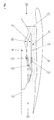
- the Fig. 1 shows a schematic representation of an engine nacelle 9 with an inlet 10, in which a fan is arranged.
- the exiting flow of the fan 11 passes into a bypass duct 4 and to a compressor 12 of a core engine 2, which comprises a combustion chamber 13 and a turbine 14.
- the flow emerging from the turbine 14 and the bypass duct 3 is supplied to a thrust nozzle 15.
- the reference numeral 16 describes an engine axis.
- a core engine ventilation space 4 is formed, which is bounded radially outward by a panel 1.
- the panel 1 is penetrated by an air guide element 17, through which cooling air, as described, is supplied for cooling the running gap by cooling a wall of a turbine housing, not shown in detail.
- the Fig. 2-5 show an inventive embodiment of the air guide 17.
- This includes a first flow channel 5, which has a substantially rectangular cross-sectional shape and is provided with a likewise substantially rectangular inlet opening 6, which is located in the bypass duct 3.
- the first flow channel 5 extends arcuately downward with a substantially constant cross-section and opens into a substantially rectangular outlet opening 18, which may be surrounded by a seal 19 (see 8 and 9 ).
- a second flow channel 7 surrounds or encloses the first flow channel 5. Its two lateral inlet openings 8 are set back in the axial direction or in the flow direction, as can be seen for example from FIGS FIGS. 2 and 3 results.
- the second flow channel is thus fork-shaped, the incoming flow surrounds the first flow channel 5 on both sides and then merges to flow out through an outlet opening 20, which can also be enclosed on a seal 21.
- FIG. 2-5 show the respective flow paths.
- the Fig. 2 shows with the two double arrows the inflow into the first flow channel 5 and into one side of the second flow channel 7 through its lateral inlet opening 8 (see also Fig. 7 ).
- the Fig. 3 shows the union of the two partial flows, which have entered through the two lateral inlet openings 8 in the second flow channel 7.
- the Fig. 4 shows in plan view the inflow regions of the first flow channel 5 and the two lateral inflow regions into the second flow channel 7.
- the flow guide is in Fig. 5 again clarified.
- the Fig. 3 . 6 and 8th show further that the first flow channel 5 is spaced in the region of its inflow opening 6 from the surface of the panel 1. This is achieved by a flow-shaped spacer element 22, so that the inlet into the inflow opening 6 is not affected by edge effects and frictional effects of the panel 1.
Abstract
Description
Die Erfindung bezieht sich auf ein Luftleitelement, welches bei einem Laufspalteinstellungssystem einer Fluggasturbine verwendet wird, um Kühlluft aus einem Nebenstromkanal in einem Kerntriebwerklüftungsraum einzuleiten.The invention relates to an air guide element which is used in a running gap adjustment system of an aircraft gas turbine to introduce cooling air from a bypass duct in a core engine ventilation space.
Im Einzelnen bezieht sich die Erfindung auf ein Luftleitelement einer Verkleidung eines Kerntriebwerks einer Gasturbine, durch welches Luft aus einer Nebenströmung zu mehreren Kühlluftverteilern zugeführt wird.In detail, the invention relates to an air guide element of a lining of a core engine of a gas turbine, through which air is supplied from a secondary flow to a plurality of cooling air distributors.
Aus dem Stand der Technik ist es bekannt, Kühlluft zur aktiven Laufspaltkontrolle aus einem Nebenstromkanal abzuzweigen und zur Kühlung der Wandung eines Turbinengehäuses zu verwenden.From the prior art it is known to divert cooling air for active clearance control from a bypass duct and to use for cooling the wall of a turbine housing.
Zum Stand der Technik wird auf die
Zur Einleitung von Kühlluft ist es erforderlich, diese strömungsgünstig aus dem Nebenstromkanal aufzunehmen und strömungsorientiert durch die Verkleidung des Kerntriebwerklüftungsraums radial nach innen zu leiten.For the introduction of cooling air, it is necessary to take these streamlined from the bypass duct and flow oriented radially through the lining of the core engine vent space radially inwards.
Der Erfindung liegt die Aufgabe zugrunde, ein Luftleitelement der eingangs genannten Art zu schaffen, welches eine strömungsoptimierte Kühllufteinleitung ermöglicht.The invention has for its object to provide an air guide element of the type mentioned, which allows a flow-optimized cooling air introduction.
Erfindungsgemäß wird die Aufgabe durch die Merkmalskombination des Anspruchs 1 gelöst, die Unteransprüche zeigen weitere vorteilhafte Ausgestaltungen der Erfindung.According to the invention the object is achieved by the combination of features of
Das erfindungsgemäße Luftleitelement (scoop) zeichnet sich durch eine Reihe erheblicher Vorteile aus. Es ist insbesondere in optimaler Weise dafür geeignet, eine Gas- oder Fluidströmung als Teilströmung aus einer anderen Strömung zu entnehmen, ohne dass sich hierbei große Strömungsverluste ergeben würden.The spoiler element according to the invention (scoop) is characterized by a number of significant advantages. In particular, it is optimally suitable for removing a gas or fluid flow as a partial flow from another flow without resulting in large flow losses.
Demgemäß ist das erfindungsgemäße Luftleitelement nicht nur für die beschriebene aktive Laufspalteinstellung verwendbar, sondern bei allen Anwendungen, bei welchen Teil-Fluidströmungen zum Kühlen, Heizen oder zu anderen Zwecken zu entnehmen sind.Accordingly, the air guide element according to the invention can be used not only for the described active gap adjustment, but in all applications in which partial fluid flows can be taken for cooling, heating or other purposes.
Erfindungsgemäß ergibt sich durch die Ausgestaltung des Luftleitelements eine strömungsgünstige Strömungsführung, welche geringe Druck- und Strömungsverluste aufweist. Dies insbesondere in der beschriebenen Kombination zweier zu entnehmender Fluidströmungen, welche praktisch an einem gleichen Ort aus einer Hauptströmung zu entnehmen sind.According to the invention results from the design of the air guide a flow-favorable flow guidance, which has low pressure and flow losses. This in particular in the described combination of two fluid flows to be taken, which can be taken practically at the same location from a main flow.
Weiterhin erweist es sich erfindungsgemäß als besonders günstig, dass das Luftleitelement in einfacher Weise gefertigt werden kann und aus einer geringen Zahl von Einzelteilen besteht. Somit vereinfacht sich der Herstellungsprozess. Insgesamt ergibt sich ein geringes Teilegewicht. Auch die Wartungskosten sind, bedingt durch den einfachen Aufbau, gering, da praktisch kein Wartungsaufwand besteht.Furthermore, it proves to be particularly favorable according to the invention that the air guide element can be manufactured in a simple manner and consists of a small number of individual parts. This simplifies the manufacturing process. Overall, results in a low part weight. The maintenance costs are due to the simple structure, low, since there is virtually no maintenance.
Erfindungsgemäß sind somit zwei Strömungskanäle einander zugeordnet, wobei ein erster, rohrförmiger Strömungskanal vorgesehen ist, welcher sich durch die Wandung oder Verkleidung erstreckt, sowie ein zweiter Strömungskanal, welcher den ersten Strömungskanal zumindest teilweise umschließt und dessen Einströmöffnung in Strömungsrichtung von der Einströmöffnung des ersten Strömungskanals rückversetzt ist. Dies führt zu dem günstigen Effekt, dass sich die beiden Einströmöffnungen und die sich hierbei ergebenden Beeinträchtigungen der ursprünglichen Gesamtströmung nicht negativ gegenseitig beeinträchtigen. Vielmehr kann eine ungestörte Einströmung durch beide Einströmöffnungen erfolgen, es treten keine Verwirbelungen oder Ablösungen der Strömung auf.According to the invention thus two flow channels are associated with each other, wherein a first, tubular flow channel is provided, which extends through the wall or panel, and a second flow channel, which at least partially encloses the first flow channel and the inflow opening in the flow direction of the inflow opening of the first flow channel is. This leads to the favorable effect that the two inlet openings and the resulting impairment of the original total flow does not negatively affect each other. Rather, an undisturbed inflow can take place through both inflow openings, there is no turbulence or separation of the flow.
Durch die erfindungsgemäße Lösung, dass der zweite Strömungskanal den ersten Strömungskanal zumindest teilweise umgreift oder umschließt, kann für beide Strömungskanäle ein effektiver und wirksamer Strömungsquerschnitt geschaffen werden, der die Hauptströmung nur minimal beeinträchtigt und ein wirksames Abführen der jeweiligen Teilströmungen gewährleistet.The inventive solution that the second flow channel at least partially surrounds or surrounds the first flow channel, an effective and effective flow cross-section can be created for both flow channels, which minimally affects the main flow and ensures effective discharge of the respective partial flows.
Im Folgenden wird die Erfindung anhand eines Ausführungsbeispiels in Verbindung mit der Zeichnung beschrieben. Dabei zeigt:
- Fig. 1
- eine vereinfachte axiale Teil-Schnittansicht einer Fluggasturbine unter Verwendung des erfindungsgemäßen Luftleitelements,
- Fig. 2, 3
- eine perspektivische Darstellung des erfindungsgemäßen Luftleitelements,
- Fig. 4, 5
- eine Draufsicht auf die Darstellung gemäß den
Fig. 2 und 3 , - Fig. 6
- eine vereinfachte Längs-Schnittansicht des gezeigten Ausführungsbeispiels,
- Fig. 7
- eine Radial-Schnittansicht längs der Linie Y-Y von
Fig. 6 , - Fig. 8
- eine vereinfachte Seiten-Schnittansicht, insbesondere der Darstellung der
Fig. 6 , und - Fig. 9
- eine perspektivische Unteransicht.
- Fig. 1
- a simplified partial axial sectional view of an aircraft gas turbine using the air guide element according to the invention,
- Fig. 2, 3rd
- a perspective view of the air guide element according to the invention,
- Fig. 4, 5
- a plan view of the representation according to the
FIGS. 2 and 3 . - Fig. 6
- a simplified longitudinal sectional view of the embodiment shown,
- Fig. 7
- a radial sectional view taken along the line YY of
Fig. 6 . - Fig. 8
- a simplified side sectional view, in particular the representation of
Fig. 6 , and - Fig. 9
- a perspective bottom view.
Die
Zwischen dem Kerntriebwerk 2 und dem Nebenstromkanal 3 ist ein Kerntriebwerklüftungsraum 4 ausgebildet, welcher radial nach außen durch eine Verkleidung 1 begrenzt wird. Die Verkleidung 1 wird durchgriffen von einem Luftleitelement 17, durch welches Kühlluft, wie beschrieben, zur Kühlung des Laufspalts durch Kühlung einer im Einzelnen nicht dargestellten Wandung eines Turbinengehäuses zugeführt wird.Between the
Die
Ein zweiter Strömungskanal 7 umgreift oder umschließt den ersten Strömungskanal 5. Seine beiden seitlichen Eintrittsöffnungen 8 sind in axialer Richtung bzw. in Strömungsrichtung zurückversetzt, so wie sich dies beispielsweise aus den
Insbesondere die
Die
- 11
- Verkleidungpaneling
- 22
- KerntriebwerkCore engine
- 33
- NebenstromkanalBypass duct
- 44
- KerntriebwerklüftungsraumCore engine room ventilation
- 55
- erster Strömungskanalfirst flow channel
- 66
- Einströmöffnunginflow
- 77
- zweiter Strömungskanalsecond flow channel
- 88th
- Eintrittsöffnunginlet opening
- 99
- TriebwerksgondelEngine nacelle
- 1010
- Einlaufenema
- 1111
- Fanfan
- 1212
- Kompressorcompressor
- 1313
- Brennkammercombustion chamber
- 1414
- Turbineturbine
- 1515
- Schubdüseexhaust nozzle
- 1616
- TriebwerksachseEngine axis
- 1717
- Luftleitelementair guide
- 1818
- Austrittsöffnungoutlet opening
- 1919
- Dichtungpoetry
- 2020
- Austrittsöffnungoutlet opening
- 2121
- Dichtungpoetry
- 2222
- Distanzelementspacer
Claims (6)
Applications Claiming Priority (1)
| Application Number | Priority Date | Filing Date | Title |
|---|---|---|---|
| DE102009011635A DE102009011635A1 (en) | 2009-03-04 | 2009-03-04 | Air guide element of a running gap adjustment system of an aircraft gas turbine |
Publications (3)
| Publication Number | Publication Date |
|---|---|
| EP2226473A2 true EP2226473A2 (en) | 2010-09-08 |
| EP2226473A3 EP2226473A3 (en) | 2016-03-02 |
| EP2226473B1 EP2226473B1 (en) | 2016-08-24 |
Family
ID=41818420
Family Applications (1)
| Application Number | Title | Priority Date | Filing Date |
|---|---|---|---|
| EP10001674.0A Not-in-force EP2226473B1 (en) | 2009-03-04 | 2010-02-18 | Air scoop of a system for tip clearance adjustment of an aero gas turbine |
Country Status (3)
| Country | Link |
|---|---|
| US (1) | US8408008B2 (en) |
| EP (1) | EP2226473B1 (en) |
| DE (1) | DE102009011635A1 (en) |
Cited By (5)
| Publication number | Priority date | Publication date | Assignee | Title |
|---|---|---|---|---|
| WO2013068671A1 (en) * | 2011-11-10 | 2013-05-16 | Aircelle | Composite panel having a built-in sampling scoop |
| CN103935524A (en) * | 2014-04-29 | 2014-07-23 | 南京航空航天大学 | High-performance subsonic speed air inlet duct integrated with inner auxiliary air inlet duct |
| EP2993307A1 (en) * | 2014-09-05 | 2016-03-09 | Rolls-Royce Deutschland Ltd & Co KG | Air directing device and turbo engine having air directing device |
| EP3246524A1 (en) * | 2016-05-06 | 2017-11-22 | United Technologies Corporation | Impingement manifold |
| EP3366909A1 (en) * | 2017-02-24 | 2018-08-29 | Unison Industries LLC | Turbine engine with thermal seal |
Families Citing this family (17)
| Publication number | Priority date | Publication date | Assignee | Title |
|---|---|---|---|---|
| EP2798229B1 (en) * | 2011-12-31 | 2019-04-17 | Rolls-Royce Corporation | Flow splitter for a fluid system of a gas turbine engine |
| US9297334B2 (en) * | 2012-05-25 | 2016-03-29 | King Abdulaziz City For Science And Technology | Exhaust nozzle of a gas turbine engine |
| US9194330B2 (en) * | 2012-07-31 | 2015-11-24 | United Technologies Corporation | Retrofitable auxiliary inlet scoop |
| FR3015569B1 (en) * | 2013-12-19 | 2019-01-25 | Safran Aircraft Engines | CARTER FOR A PROPULSIVE ASSEMBLY |
| EP2918787B1 (en) * | 2014-03-12 | 2017-10-18 | Rolls-Royce Deutschland Ltd & Co KG | Flow guiding system and rotary combustion engine |
| FR3021994B1 (en) * | 2014-06-04 | 2019-04-05 | Safran Aircraft Engines | ECOPE FOR A SYSTEM FOR COOLING AND CONTROLLING THE GAMES OF A TURBOMACHINE TURBINE |
| EP2957755A1 (en) * | 2014-06-18 | 2015-12-23 | United Technologies Corporation | Nacelle air scoop assembly |
| DE102014217831A1 (en) * | 2014-09-05 | 2016-03-10 | Rolls-Royce Deutschland Ltd & Co Kg | Device for drawing bleed air and aircraft engine with at least one device for drawing bleed air |
| FR3028289B1 (en) * | 2014-11-06 | 2019-12-27 | Airbus Operations (S.A.S.) | AIRCRAFT TURBOMACHINE COMPRISING AN AIR INTAKE BOX WITH VARIABLE AERODYNAMIC PROFILE |
| DE102014223548A1 (en) | 2014-11-18 | 2016-05-19 | Rolls-Royce Deutschland Ltd & Co Kg | Fully integrated air guide element |
| US20160153363A1 (en) * | 2014-12-01 | 2016-06-02 | United Technologies Corporation | Liquid separating air inlets |
| GB201705802D0 (en) * | 2017-04-11 | 2017-05-24 | Rolls Royce Plc | Inlet duct |
| FR3067387B1 (en) | 2017-06-07 | 2019-06-28 | Safran Aircraft Engines | AIR SUPPLY ECOPE FOR SUPPLYING A COOLING SYSTEM AND CONTROLLING THE GAMES OF A TURBINE |
| CN107298180B (en) * | 2017-06-09 | 2018-08-31 | 南京航空航天大学 | A kind of aircraft having one flowing control and pneumatic adaptation design method |
| GB201808352D0 (en) * | 2018-05-22 | 2018-07-11 | Rolls Royce Plc | Air intake system |
| CN110513162B (en) | 2018-05-22 | 2022-06-14 | 通用电气公司 | Bucket type entrance |
| CN113606045B (en) * | 2021-07-15 | 2022-07-12 | 南京航空航天大学 | Large-bypass-ratio turbofan engine core cabin ventilation structure and ventilation method thereof |
Citations (3)
| Publication number | Priority date | Publication date | Assignee | Title |
|---|---|---|---|---|
| US20070140838A1 (en) | 2005-12-16 | 2007-06-21 | Estridge Scott A | System and method to exhaust spent cooling air of gas turbine engine active clearance control |
| US20070140839A1 (en) | 2005-12-16 | 2007-06-21 | Bucaro Michael T | Thermal control of gas turbine engine rings for active clearance control |
| US20070245711A1 (en) | 2006-04-20 | 2007-10-25 | Rolls-Royce Plc | Aeroengine ventilation system |
Family Cites Families (10)
| Publication number | Priority date | Publication date | Assignee | Title |
|---|---|---|---|---|
| DE3546839C2 (en) * | 1985-11-19 | 1995-05-04 | Mtu Muenchen Gmbh | By-pass turbojet engine with split compressor |
| FR2614073B1 (en) | 1987-04-15 | 1992-02-14 | Snecma | REAL-TIME ADJUSTMENT DEVICE OF THE RADIAL GAME BETWEEN A ROTOR AND A TURBOMACHINE STATOR |
| GB9027986D0 (en) | 1990-12-22 | 1991-02-13 | Rolls Royce Plc | Gas turbine engine clearance control |
| US5269135A (en) | 1991-10-28 | 1993-12-14 | General Electric Company | Gas turbine engine fan cooled heat exchanger |
| US5351478A (en) * | 1992-05-29 | 1994-10-04 | General Electric Company | Compressor casing assembly |
| US5826794A (en) | 1997-02-28 | 1998-10-27 | The Boeing Company | Aircraft scoop ejector nozzle |
| US6058696A (en) | 1997-12-22 | 2000-05-09 | United Technologies Corporation | Inlet and outlet module for a heat exchanger for a flowpath for working medium gases |
| WO2006091138A1 (en) * | 2005-02-25 | 2006-08-31 | Volvo Aero Corporation | A bleed structure for a bleed passage in a gas turbine engine |
| US7717667B2 (en) * | 2006-09-29 | 2010-05-18 | General Electric Company | Method and apparatus for operating gas turbine engines |
| US7861968B2 (en) * | 2006-10-26 | 2011-01-04 | The Boeing Company | Air inlet and method for a highspeed mobile platform |
-
2009
- 2009-03-04 DE DE102009011635A patent/DE102009011635A1/en not_active Withdrawn
-
2010
- 2010-02-18 EP EP10001674.0A patent/EP2226473B1/en not_active Not-in-force
- 2010-03-03 US US12/716,741 patent/US8408008B2/en not_active Expired - Fee Related
Patent Citations (3)
| Publication number | Priority date | Publication date | Assignee | Title |
|---|---|---|---|---|
| US20070140838A1 (en) | 2005-12-16 | 2007-06-21 | Estridge Scott A | System and method to exhaust spent cooling air of gas turbine engine active clearance control |
| US20070140839A1 (en) | 2005-12-16 | 2007-06-21 | Bucaro Michael T | Thermal control of gas turbine engine rings for active clearance control |
| US20070245711A1 (en) | 2006-04-20 | 2007-10-25 | Rolls-Royce Plc | Aeroengine ventilation system |
Cited By (10)
| Publication number | Priority date | Publication date | Assignee | Title |
|---|---|---|---|---|
| WO2013068671A1 (en) * | 2011-11-10 | 2013-05-16 | Aircelle | Composite panel having a built-in sampling scoop |
| FR2982588A1 (en) * | 2011-11-10 | 2013-05-17 | Aircelle Sa | COMPOSITE PANEL WITH INTEGRATED SAMPLING ECOPE |
| US9410485B2 (en) | 2011-11-10 | 2016-08-09 | Aircelle | Composite panel having a built-in duct |
| CN103935524A (en) * | 2014-04-29 | 2014-07-23 | 南京航空航天大学 | High-performance subsonic speed air inlet duct integrated with inner auxiliary air inlet duct |
| EP2993307A1 (en) * | 2014-09-05 | 2016-03-09 | Rolls-Royce Deutschland Ltd & Co KG | Air directing device and turbo engine having air directing device |
| US10054054B2 (en) | 2014-09-05 | 2018-08-21 | Rolls-Royce Deutschland Ltd & Co Kg | Air guiding device and turbo engine with air guiding device |
| EP3246524A1 (en) * | 2016-05-06 | 2017-11-22 | United Technologies Corporation | Impingement manifold |
| US10329941B2 (en) | 2016-05-06 | 2019-06-25 | United Technologies Corporation | Impingement manifold |
| EP3366909A1 (en) * | 2017-02-24 | 2018-08-29 | Unison Industries LLC | Turbine engine with thermal seal |
| US10514005B2 (en) | 2017-02-24 | 2019-12-24 | Unison Industries, Llc | Turbine engine thermal seal |
Also Published As
| Publication number | Publication date |
|---|---|
| US8408008B2 (en) | 2013-04-02 |
| EP2226473A3 (en) | 2016-03-02 |
| EP2226473B1 (en) | 2016-08-24 |
| DE102009011635A1 (en) | 2010-09-09 |
| US20100223905A1 (en) | 2010-09-09 |
Similar Documents
| Publication | Publication Date | Title |
|---|---|---|
| EP2226473B1 (en) | Air scoop of a system for tip clearance adjustment of an aero gas turbine | |
| EP0126399B1 (en) | Fluid duct presenting a reduced construction | |
| EP0955235A2 (en) | Boundary layer suction device for aircraft | |
| DE10019437A1 (en) | Method and device for cooling the housings of turbines of jet engines | |
| DE102009011924A1 (en) | Bypass duct of a turbofan engine | |
| DE102015201805A1 (en) | turbocharger | |
| DE102009010647A1 (en) | Running column adjustment system of an aircraft gas turbine | |
| DE1070880B (en) | Gas turbine unit with turbo compressor | |
| EP1716380A1 (en) | Arrangement for cooling the exhaust gas of a motor vehicle | |
| EP2881548A1 (en) | Gas turbine compressor | |
| DE102014221049A1 (en) | Arrangement and method for blowing off compressor air in an engine | |
| DE102017130568A1 (en) | Discharge nozzle for a turbofan engine of a supersonic aircraft | |
| WO1989007194A1 (en) | Turbine for an exhaust gas turbocharger | |
| DE1233660B (en) | Ring-shaped incinerator for gas turbine jet engines | |
| DE102004042295A1 (en) | Rotor for an engine | |
| DE102011012039A1 (en) | Duct section for use as ring diffuser for axial blower with post-guide vane, has annular components subdividing duct cross-section into sub ducts, where displacement thickness of parts of components is increased in flow direction upto ends | |
| EP3462090A1 (en) | Nozzle with axial extension for a combustion chamber of an engine | |
| DE102007019056A1 (en) | Fan for extractor fan | |
| EP3124742A1 (en) | Gas turbine | |
| DE10162238A1 (en) | Air intake system of a PTL drive | |
| DE102014209452A1 (en) | Air conditioning with bypass device | |
| DE69728222T2 (en) | Arrangement and method for regulating the diameter of a vane ring | |
| DE102010044819B4 (en) | Axial flow turbine and method of removing flow from an axial flow turbine | |
| DE102004015829B4 (en) | intake | |
| DE102016004850A1 (en) | Humidifier for a fuel cell system. Fuel cell system and vehicle |
Legal Events
| Date | Code | Title | Description |
|---|---|---|---|
| PUAI | Public reference made under article 153(3) epc to a published international application that has entered the european phase |
Free format text: ORIGINAL CODE: 0009012 |
|
| AK | Designated contracting states |
Kind code of ref document: A2 Designated state(s): AT BE BG CH CY CZ DE DK EE ES FI FR GB GR HR HU IE IS IT LI LT LU LV MC MK MT NL NO PL PT RO SE SI SK SM TR |
|
| AX | Request for extension of the european patent |
Extension state: AL BA RS |
|
| PUAL | Search report despatched |
Free format text: ORIGINAL CODE: 0009013 |
|
| AK | Designated contracting states |
Kind code of ref document: A3 Designated state(s): AT BE BG CH CY CZ DE DK EE ES FI FR GB GR HR HU IE IS IT LI LT LU LV MC MK MT NL NO PL PT RO SE SI SK SM TR |
|
| AX | Request for extension of the european patent |
Extension state: AL BA RS |
|
| RIC1 | Information provided on ipc code assigned before grant |
Ipc: F01D 25/14 20060101ALI20160125BHEP Ipc: F01D 11/24 20060101AFI20160125BHEP Ipc: F02C 7/06 20060101ALI20160125BHEP Ipc: F02K 3/04 20060101ALI20160125BHEP Ipc: F02C 9/18 20060101ALI20160125BHEP Ipc: F02C 7/18 20060101ALI20160125BHEP |
|
| 17P | Request for examination filed |
Effective date: 20160225 |
|
| RBV | Designated contracting states (corrected) |
Designated state(s): AT BE BG CH CY CZ DE DK EE ES FI FR GB GR HR HU IE IS IT LI LT LU LV MC MK MT NL NO PL PT RO SE SI SK SM TR |
|
| GRAP | Despatch of communication of intention to grant a patent |
Free format text: ORIGINAL CODE: EPIDOSNIGR1 |
|
| INTG | Intention to grant announced |
Effective date: 20160422 |
|
| GRAS | Grant fee paid |
Free format text: ORIGINAL CODE: EPIDOSNIGR3 |
|
| GRAA | (expected) grant |
Free format text: ORIGINAL CODE: 0009210 |
|
| AK | Designated contracting states |
Kind code of ref document: B1 Designated state(s): AT BE BG CH CY CZ DE DK EE ES FI FR GB GR HR HU IE IS IT LI LT LU LV MC MK MT NL NO PL PT RO SE SI SK SM TR |
|
| REG | Reference to a national code |
Ref country code: GB Ref legal event code: FG4D Free format text: NOT ENGLISH |
|
| RIN1 | Information on inventor provided before grant (corrected) |
Inventor name: HERZOG, STEPHAN Inventor name: TODOROVIC, PREDRAG Inventor name: SEYDEL, CHRISTIAN |
|
| REG | Reference to a national code |
Ref country code: CH Ref legal event code: EP |
|
| REG | Reference to a national code |
Ref country code: AT Ref legal event code: REF Ref document number: 823301 Country of ref document: AT Kind code of ref document: T Effective date: 20160915 |
|
| REG | Reference to a national code |
Ref country code: IE Ref legal event code: FG4D Free format text: LANGUAGE OF EP DOCUMENT: GERMAN |
|
| REG | Reference to a national code |
Ref country code: DE Ref legal event code: R096 Ref document number: 502010012241 Country of ref document: DE |
|
| REG | Reference to a national code |
Ref country code: LT Ref legal event code: MG4D |
|
| REG | Reference to a national code |
Ref country code: NL Ref legal event code: MP Effective date: 20160824 |
|
| PG25 | Lapsed in a contracting state [announced via postgrant information from national office to epo] |
Ref country code: FI Free format text: LAPSE BECAUSE OF FAILURE TO SUBMIT A TRANSLATION OF THE DESCRIPTION OR TO PAY THE FEE WITHIN THE PRESCRIBED TIME-LIMIT Effective date: 20160824 Ref country code: HR Free format text: LAPSE BECAUSE OF FAILURE TO SUBMIT A TRANSLATION OF THE DESCRIPTION OR TO PAY THE FEE WITHIN THE PRESCRIBED TIME-LIMIT Effective date: 20160824 Ref country code: NO Free format text: LAPSE BECAUSE OF FAILURE TO SUBMIT A TRANSLATION OF THE DESCRIPTION OR TO PAY THE FEE WITHIN THE PRESCRIBED TIME-LIMIT Effective date: 20161124 Ref country code: LT Free format text: LAPSE BECAUSE OF FAILURE TO SUBMIT A TRANSLATION OF THE DESCRIPTION OR TO PAY THE FEE WITHIN THE PRESCRIBED TIME-LIMIT Effective date: 20160824 Ref country code: NL Free format text: LAPSE BECAUSE OF FAILURE TO SUBMIT A TRANSLATION OF THE DESCRIPTION OR TO PAY THE FEE WITHIN THE PRESCRIBED TIME-LIMIT Effective date: 20160824 Ref country code: IT Free format text: LAPSE BECAUSE OF FAILURE TO SUBMIT A TRANSLATION OF THE DESCRIPTION OR TO PAY THE FEE WITHIN THE PRESCRIBED TIME-LIMIT Effective date: 20160824 |
|
| REG | Reference to a national code |
Ref country code: FR Ref legal event code: PLFP Year of fee payment: 8 |
|
| PG25 | Lapsed in a contracting state [announced via postgrant information from national office to epo] |
Ref country code: LV Free format text: LAPSE BECAUSE OF FAILURE TO SUBMIT A TRANSLATION OF THE DESCRIPTION OR TO PAY THE FEE WITHIN THE PRESCRIBED TIME-LIMIT Effective date: 20160824 Ref country code: GR Free format text: LAPSE BECAUSE OF FAILURE TO SUBMIT A TRANSLATION OF THE DESCRIPTION OR TO PAY THE FEE WITHIN THE PRESCRIBED TIME-LIMIT Effective date: 20161125 Ref country code: ES Free format text: LAPSE BECAUSE OF FAILURE TO SUBMIT A TRANSLATION OF THE DESCRIPTION OR TO PAY THE FEE WITHIN THE PRESCRIBED TIME-LIMIT Effective date: 20160824 Ref country code: SE Free format text: LAPSE BECAUSE OF FAILURE TO SUBMIT A TRANSLATION OF THE DESCRIPTION OR TO PAY THE FEE WITHIN THE PRESCRIBED TIME-LIMIT Effective date: 20160824 Ref country code: PT Free format text: LAPSE BECAUSE OF FAILURE TO SUBMIT A TRANSLATION OF THE DESCRIPTION OR TO PAY THE FEE WITHIN THE PRESCRIBED TIME-LIMIT Effective date: 20161226 |
|
| PG25 | Lapsed in a contracting state [announced via postgrant information from national office to epo] |
Ref country code: RO Free format text: LAPSE BECAUSE OF FAILURE TO SUBMIT A TRANSLATION OF THE DESCRIPTION OR TO PAY THE FEE WITHIN THE PRESCRIBED TIME-LIMIT Effective date: 20160824 Ref country code: EE Free format text: LAPSE BECAUSE OF FAILURE TO SUBMIT A TRANSLATION OF THE DESCRIPTION OR TO PAY THE FEE WITHIN THE PRESCRIBED TIME-LIMIT Effective date: 20160824 |
|
| REG | Reference to a national code |
Ref country code: DE Ref legal event code: R097 Ref document number: 502010012241 Country of ref document: DE |
|
| PG25 | Lapsed in a contracting state [announced via postgrant information from national office to epo] |
Ref country code: SM Free format text: LAPSE BECAUSE OF FAILURE TO SUBMIT A TRANSLATION OF THE DESCRIPTION OR TO PAY THE FEE WITHIN THE PRESCRIBED TIME-LIMIT Effective date: 20160824 Ref country code: CZ Free format text: LAPSE BECAUSE OF FAILURE TO SUBMIT A TRANSLATION OF THE DESCRIPTION OR TO PAY THE FEE WITHIN THE PRESCRIBED TIME-LIMIT Effective date: 20160824 Ref country code: SK Free format text: LAPSE BECAUSE OF FAILURE TO SUBMIT A TRANSLATION OF THE DESCRIPTION OR TO PAY THE FEE WITHIN THE PRESCRIBED TIME-LIMIT Effective date: 20160824 Ref country code: BE Free format text: LAPSE BECAUSE OF NON-PAYMENT OF DUE FEES Effective date: 20170228 Ref country code: BG Free format text: LAPSE BECAUSE OF FAILURE TO SUBMIT A TRANSLATION OF THE DESCRIPTION OR TO PAY THE FEE WITHIN THE PRESCRIBED TIME-LIMIT Effective date: 20161124 Ref country code: DK Free format text: LAPSE BECAUSE OF FAILURE TO SUBMIT A TRANSLATION OF THE DESCRIPTION OR TO PAY THE FEE WITHIN THE PRESCRIBED TIME-LIMIT Effective date: 20160824 Ref country code: PL Free format text: LAPSE BECAUSE OF FAILURE TO SUBMIT A TRANSLATION OF THE DESCRIPTION OR TO PAY THE FEE WITHIN THE PRESCRIBED TIME-LIMIT Effective date: 20160824 |
|
| PLBE | No opposition filed within time limit |
Free format text: ORIGINAL CODE: 0009261 |
|
| STAA | Information on the status of an ep patent application or granted ep patent |
Free format text: STATUS: NO OPPOSITION FILED WITHIN TIME LIMIT |
|
| 26N | No opposition filed |
Effective date: 20170526 |
|
| PG25 | Lapsed in a contracting state [announced via postgrant information from national office to epo] |
Ref country code: SI Free format text: LAPSE BECAUSE OF FAILURE TO SUBMIT A TRANSLATION OF THE DESCRIPTION OR TO PAY THE FEE WITHIN THE PRESCRIBED TIME-LIMIT Effective date: 20160824 |
|
| PG25 | Lapsed in a contracting state [announced via postgrant information from national office to epo] |
Ref country code: MC Free format text: LAPSE BECAUSE OF FAILURE TO SUBMIT A TRANSLATION OF THE DESCRIPTION OR TO PAY THE FEE WITHIN THE PRESCRIBED TIME-LIMIT Effective date: 20160824 |
|
| REG | Reference to a national code |
Ref country code: CH Ref legal event code: PL |
|
| PG25 | Lapsed in a contracting state [announced via postgrant information from national office to epo] |
Ref country code: CH Free format text: LAPSE BECAUSE OF NON-PAYMENT OF DUE FEES Effective date: 20170228 Ref country code: LI Free format text: LAPSE BECAUSE OF NON-PAYMENT OF DUE FEES Effective date: 20170228 |
|
| REG | Reference to a national code |
Ref country code: IE Ref legal event code: MM4A |
|
| PG25 | Lapsed in a contracting state [announced via postgrant information from national office to epo] |
Ref country code: LU Free format text: LAPSE BECAUSE OF NON-PAYMENT OF DUE FEES Effective date: 20170218 |
|
| REG | Reference to a national code |
Ref country code: BE Ref legal event code: MM Effective date: 20170228 |
|
| REG | Reference to a national code |
Ref country code: FR Ref legal event code: PLFP Year of fee payment: 9 |
|
| PG25 | Lapsed in a contracting state [announced via postgrant information from national office to epo] |
Ref country code: IE Free format text: LAPSE BECAUSE OF NON-PAYMENT OF DUE FEES Effective date: 20170218 |
|
| REG | Reference to a national code |
Ref country code: AT Ref legal event code: MM01 Ref document number: 823301 Country of ref document: AT Kind code of ref document: T Effective date: 20170218 |
|
| PG25 | Lapsed in a contracting state [announced via postgrant information from national office to epo] |
Ref country code: AT Free format text: LAPSE BECAUSE OF NON-PAYMENT OF DUE FEES Effective date: 20170218 |
|
| PG25 | Lapsed in a contracting state [announced via postgrant information from national office to epo] |
Ref country code: MT Free format text: LAPSE BECAUSE OF FAILURE TO SUBMIT A TRANSLATION OF THE DESCRIPTION OR TO PAY THE FEE WITHIN THE PRESCRIBED TIME-LIMIT Effective date: 20160824 |
|
| PG25 | Lapsed in a contracting state [announced via postgrant information from national office to epo] |
Ref country code: HU Free format text: LAPSE BECAUSE OF FAILURE TO SUBMIT A TRANSLATION OF THE DESCRIPTION OR TO PAY THE FEE WITHIN THE PRESCRIBED TIME-LIMIT; INVALID AB INITIO Effective date: 20100218 |
|
| PG25 | Lapsed in a contracting state [announced via postgrant information from national office to epo] |
Ref country code: CY Free format text: LAPSE BECAUSE OF NON-PAYMENT OF DUE FEES Effective date: 20160824 |
|
| PG25 | Lapsed in a contracting state [announced via postgrant information from national office to epo] |
Ref country code: MK Free format text: LAPSE BECAUSE OF FAILURE TO SUBMIT A TRANSLATION OF THE DESCRIPTION OR TO PAY THE FEE WITHIN THE PRESCRIBED TIME-LIMIT Effective date: 20160824 |
|
| PG25 | Lapsed in a contracting state [announced via postgrant information from national office to epo] |
Ref country code: TR Free format text: LAPSE BECAUSE OF FAILURE TO SUBMIT A TRANSLATION OF THE DESCRIPTION OR TO PAY THE FEE WITHIN THE PRESCRIBED TIME-LIMIT Effective date: 20160824 |
|
| PGFP | Annual fee paid to national office [announced via postgrant information from national office to epo] |
Ref country code: GB Payment date: 20200227 Year of fee payment: 11 Ref country code: DE Payment date: 20200227 Year of fee payment: 11 |
|
| PGFP | Annual fee paid to national office [announced via postgrant information from national office to epo] |
Ref country code: FR Payment date: 20200225 Year of fee payment: 11 |
|
| PG25 | Lapsed in a contracting state [announced via postgrant information from national office to epo] |
Ref country code: IS Free format text: LAPSE BECAUSE OF FAILURE TO SUBMIT A TRANSLATION OF THE DESCRIPTION OR TO PAY THE FEE WITHIN THE PRESCRIBED TIME-LIMIT Effective date: 20161224 |
|
| REG | Reference to a national code |
Ref country code: DE Ref legal event code: R082 Ref document number: 502010012241 Country of ref document: DE |
|
| REG | Reference to a national code |
Ref country code: DE Ref legal event code: R119 Ref document number: 502010012241 Country of ref document: DE |
|
| GBPC | Gb: european patent ceased through non-payment of renewal fee |
Effective date: 20210218 |
|
| PG25 | Lapsed in a contracting state [announced via postgrant information from national office to epo] |
Ref country code: FR Free format text: LAPSE BECAUSE OF NON-PAYMENT OF DUE FEES Effective date: 20210228 Ref country code: GB Free format text: LAPSE BECAUSE OF NON-PAYMENT OF DUE FEES Effective date: 20210218 Ref country code: DE Free format text: LAPSE BECAUSE OF NON-PAYMENT OF DUE FEES Effective date: 20210901 |