EP3246524A1 - Impingement manifold - Google Patents
Impingement manifold Download PDFInfo
- Publication number
- EP3246524A1 EP3246524A1 EP17169950.7A EP17169950A EP3246524A1 EP 3246524 A1 EP3246524 A1 EP 3246524A1 EP 17169950 A EP17169950 A EP 17169950A EP 3246524 A1 EP3246524 A1 EP 3246524A1
- Authority
- EP
- European Patent Office
- Prior art keywords
- manifold
- flow
- impingement
- lobe
- lobes
- Prior art date
- Legal status (The legal status is an assumption and is not a legal conclusion. Google has not performed a legal analysis and makes no representation as to the accuracy of the status listed.)
- Granted
Links
Images


Classifications
-
- F—MECHANICAL ENGINEERING; LIGHTING; HEATING; WEAPONS; BLASTING
- F01—MACHINES OR ENGINES IN GENERAL; ENGINE PLANTS IN GENERAL; STEAM ENGINES
- F01D—NON-POSITIVE DISPLACEMENT MACHINES OR ENGINES, e.g. STEAM TURBINES
- F01D11/00—Preventing or minimising internal leakage of working-fluid, e.g. between stages
- F01D11/08—Preventing or minimising internal leakage of working-fluid, e.g. between stages for sealing space between rotor blade tips and stator
- F01D11/14—Adjusting or regulating tip-clearance, i.e. distance between rotor-blade tips and stator casing
- F01D11/20—Actively adjusting tip-clearance
- F01D11/24—Actively adjusting tip-clearance by selectively cooling-heating stator or rotor components
-
- F—MECHANICAL ENGINEERING; LIGHTING; HEATING; WEAPONS; BLASTING
- F01—MACHINES OR ENGINES IN GENERAL; ENGINE PLANTS IN GENERAL; STEAM ENGINES
- F01D—NON-POSITIVE DISPLACEMENT MACHINES OR ENGINES, e.g. STEAM TURBINES
- F01D11/00—Preventing or minimising internal leakage of working-fluid, e.g. between stages
- F01D11/08—Preventing or minimising internal leakage of working-fluid, e.g. between stages for sealing space between rotor blade tips and stator
- F01D11/14—Adjusting or regulating tip-clearance, i.e. distance between rotor-blade tips and stator casing
- F01D11/20—Actively adjusting tip-clearance
-
- F—MECHANICAL ENGINEERING; LIGHTING; HEATING; WEAPONS; BLASTING
- F01—MACHINES OR ENGINES IN GENERAL; ENGINE PLANTS IN GENERAL; STEAM ENGINES
- F01D—NON-POSITIVE DISPLACEMENT MACHINES OR ENGINES, e.g. STEAM TURBINES
- F01D25/00—Component parts, details, or accessories, not provided for in, or of interest apart from, other groups
- F01D25/08—Cooling; Heating; Heat-insulation
- F01D25/12—Cooling
-
- F—MECHANICAL ENGINEERING; LIGHTING; HEATING; WEAPONS; BLASTING
- F02—COMBUSTION ENGINES; HOT-GAS OR COMBUSTION-PRODUCT ENGINE PLANTS
- F02C—GAS-TURBINE PLANTS; AIR INTAKES FOR JET-PROPULSION PLANTS; CONTROLLING FUEL SUPPLY IN AIR-BREATHING JET-PROPULSION PLANTS
- F02C3/00—Gas-turbine plants characterised by the use of combustion products as the working fluid
- F02C3/04—Gas-turbine plants characterised by the use of combustion products as the working fluid having a turbine driving a compressor
-
- F—MECHANICAL ENGINEERING; LIGHTING; HEATING; WEAPONS; BLASTING
- F02—COMBUSTION ENGINES; HOT-GAS OR COMBUSTION-PRODUCT ENGINE PLANTS
- F02C—GAS-TURBINE PLANTS; AIR INTAKES FOR JET-PROPULSION PLANTS; CONTROLLING FUEL SUPPLY IN AIR-BREATHING JET-PROPULSION PLANTS
- F02C6/00—Plural gas-turbine plants; Combinations of gas-turbine plants with other apparatus; Adaptations of gas- turbine plants for special use
- F02C6/04—Gas-turbine plants providing heated or pressurised working fluid for other apparatus, e.g. without mechanical power output
- F02C6/06—Gas-turbine plants providing heated or pressurised working fluid for other apparatus, e.g. without mechanical power output providing compressed gas
- F02C6/08—Gas-turbine plants providing heated or pressurised working fluid for other apparatus, e.g. without mechanical power output providing compressed gas the gas being bled from the gas-turbine compressor
-
- F—MECHANICAL ENGINEERING; LIGHTING; HEATING; WEAPONS; BLASTING
- F02—COMBUSTION ENGINES; HOT-GAS OR COMBUSTION-PRODUCT ENGINE PLANTS
- F02C—GAS-TURBINE PLANTS; AIR INTAKES FOR JET-PROPULSION PLANTS; CONTROLLING FUEL SUPPLY IN AIR-BREATHING JET-PROPULSION PLANTS
- F02C7/00—Features, components parts, details or accessories, not provided for in, or of interest apart form groups F02C1/00 - F02C6/00; Air intakes for jet-propulsion plants
- F02C7/12—Cooling of plants
- F02C7/16—Cooling of plants characterised by cooling medium
- F02C7/18—Cooling of plants characterised by cooling medium the medium being gaseous, e.g. air
-
- F—MECHANICAL ENGINEERING; LIGHTING; HEATING; WEAPONS; BLASTING
- F05—INDEXING SCHEMES RELATING TO ENGINES OR PUMPS IN VARIOUS SUBCLASSES OF CLASSES F01-F04
- F05D—INDEXING SCHEME FOR ASPECTS RELATING TO NON-POSITIVE-DISPLACEMENT MACHINES OR ENGINES, GAS-TURBINES OR JET-PROPULSION PLANTS
- F05D2220/00—Application
- F05D2220/30—Application in turbines
- F05D2220/32—Application in turbines in gas turbines
-
- F—MECHANICAL ENGINEERING; LIGHTING; HEATING; WEAPONS; BLASTING
- F05—INDEXING SCHEMES RELATING TO ENGINES OR PUMPS IN VARIOUS SUBCLASSES OF CLASSES F01-F04
- F05D—INDEXING SCHEME FOR ASPECTS RELATING TO NON-POSITIVE-DISPLACEMENT MACHINES OR ENGINES, GAS-TURBINES OR JET-PROPULSION PLANTS
- F05D2240/00—Components
- F05D2240/10—Stators
- F05D2240/12—Fluid guiding means, e.g. vanes
-
- F—MECHANICAL ENGINEERING; LIGHTING; HEATING; WEAPONS; BLASTING
- F05—INDEXING SCHEMES RELATING TO ENGINES OR PUMPS IN VARIOUS SUBCLASSES OF CLASSES F01-F04
- F05D—INDEXING SCHEME FOR ASPECTS RELATING TO NON-POSITIVE-DISPLACEMENT MACHINES OR ENGINES, GAS-TURBINES OR JET-PROPULSION PLANTS
- F05D2240/00—Components
- F05D2240/20—Rotors
- F05D2240/30—Characteristics of rotor blades, i.e. of any element transforming dynamic fluid energy to or from rotational energy and being attached to a rotor
-
- F—MECHANICAL ENGINEERING; LIGHTING; HEATING; WEAPONS; BLASTING
- F05—INDEXING SCHEMES RELATING TO ENGINES OR PUMPS IN VARIOUS SUBCLASSES OF CLASSES F01-F04
- F05D—INDEXING SCHEME FOR ASPECTS RELATING TO NON-POSITIVE-DISPLACEMENT MACHINES OR ENGINES, GAS-TURBINES OR JET-PROPULSION PLANTS
- F05D2260/00—Function
- F05D2260/20—Heat transfer, e.g. cooling
- F05D2260/201—Heat transfer, e.g. cooling by impingement of a fluid
-
- F—MECHANICAL ENGINEERING; LIGHTING; HEATING; WEAPONS; BLASTING
- F05—INDEXING SCHEMES RELATING TO ENGINES OR PUMPS IN VARIOUS SUBCLASSES OF CLASSES F01-F04
- F05D—INDEXING SCHEME FOR ASPECTS RELATING TO NON-POSITIVE-DISPLACEMENT MACHINES OR ENGINES, GAS-TURBINES OR JET-PROPULSION PLANTS
- F05D2300/00—Materials; Properties thereof
- F05D2300/50—Intrinsic material properties or characteristics
- F05D2300/502—Thermal properties
- F05D2300/5021—Expansivity
-
- Y—GENERAL TAGGING OF NEW TECHNOLOGICAL DEVELOPMENTS; GENERAL TAGGING OF CROSS-SECTIONAL TECHNOLOGIES SPANNING OVER SEVERAL SECTIONS OF THE IPC; TECHNICAL SUBJECTS COVERED BY FORMER USPC CROSS-REFERENCE ART COLLECTIONS [XRACs] AND DIGESTS
- Y02—TECHNOLOGIES OR APPLICATIONS FOR MITIGATION OR ADAPTATION AGAINST CLIMATE CHANGE
- Y02T—CLIMATE CHANGE MITIGATION TECHNOLOGIES RELATED TO TRANSPORTATION
- Y02T50/00—Aeronautics or air transport
- Y02T50/60—Efficient propulsion technologies, e.g. for aircraft
Definitions
- the present disclosure relates generally to impingement manifolds, and more specifically to gas turbine engine impingement manifolds including specialized flow features.
- Gas turbine engines include a compressor that compresses air, a combustor that ignites the compressed air and a turbine across which the compressed air is expanded. The expansion of the combustion products drives the turbine to rotate, which in turn drives rotation of the compressor.
- a fan is included forward of the compressor section, and driven to rotate by the turbine as well.
- a clearance between the tips of rotors in the primary flowpath and an inner diameter of the primary flowpath is kept sufficiently small that a minimum amount of air passes between the tip of the rotor and the outer diameter of the flowpath, while still allowing sufficient space that the tip of the rotor does not contact the outer diameter.
- an impingement manifold includes a fluid inlet passage, a pressurized chamber including at least one lobe, the at least one lobe including a flow improving feature configured to minimize vorticity of a flow field within the pressurized chamber, and at least one flow outlet.
- the flow improving feature is at least one of an inward protruding dimple and an outward protruding bulge in at least one wall defining the at least one lobe.
- the at least one flow outlet has a first cross sectional area normal to an expected direction of fluid flow
- the fluid inlet passage has a second cross sectional area normal to an expected direction of fluid flow, and wherein the first cross sectional area is less than the second cross sectional area
- the at least one lobe includes a plurality of lobes and each of the lobes in the plurality of lobes includes a pressurized fluid outlet.
- the plurality of lobes includes four lobes.
- the plurality of lobes includes three lobes.
- an interior surface of the manifold is a continuous interior surface.
- the continuous interior surface is configured to alter a direction of flow through the manifold by an angle within the range of 35-55 degrees.
- the continuous interior surface is configured to alter a direction of flow through the manifold by an angle of approximately 45 degrees.
- the manifold is constructed at least partially of joined shaped sheet metal pieces.
- a ratio of the radius of curvature to a width of the pressurized chamber at the curvature is within the range of 2 to 3 for at least a portion of an interior surface of the pressurized chamber.
- a method for providing a cooling flow to an aircraft component includes passing a cooling flow through a manifold including a pressurized chamber having at least one lobe including a flow improving feature configured to minimize vorticity of a flow field within the pressurized chamber.
- any of the above described exemplary methods for providing cooling flow to an aircraft component passing the cooling flow through the manifold includes directing the cooling flow using a continuous interior surface of the manifold.
- passing the cooling flow through the manifold includes passing the cooling flow through at least one of a plurality of lobes.
- any of the above described exemplary methods for providing cooling flow to an aircraft component passing the cooling flow through the manifold includes splitting the cooling flow, such that a portion of the cooling flow is passed through each lobe in the plurality of lobes.
- a gas turbine engine in another aspect, includes a compressor section partially defining a primary flowpath, a combustor section fluidly connected to the compressor section and partially defining the primary flowpath, a turbine section fluidly connected to the combustor section and partially defining the primary flowpath, and a fluid manifold including a continuous interior surface.
- the fluid manifold may comprise any of the features described above and/or claimed in claims 1 to 9.
- the fluid manifold is a component of an active clearance control system configured radially outward of at least one of a compressor stage and a turbine stage, and wherein the fluid manifold includes a fluid inlet passage, a pressurized chamber including at least one lobe, the at least one lobe including a flow improving feature configured to minimize vorticity of a flow field within the pressurized chamber, and at least one flow outlet.
- FIG. 1 schematically illustrates a gas turbine engine 20.
- the gas turbine engine 20 is disclosed herein as a two-spool turbofan that generally incorporates a fan section 22, a compressor section 24, a combustor section 26 and a turbine section 28.
- Alternative engines might include an augmentor section (not shown) among other systems or features.
- the fan section 22 drives air along a bypass flow path B in a bypass duct defined within a nacelle 15, while the compressor section 24 drives air along a core flow path C for compression and communication into the combustor section 26 then expansion through the turbine section 28.
- the exemplary engine 20 generally includes a low speed spool 30 and a high speed spool 32 mounted for rotation about an engine central longitudinal axis A relative to an engine static structure 36 via several bearing systems 38. It should be understood that various bearing systems 38 at various locations may alternatively or additionally be provided, and the location of bearing systems 38 may be varied as appropriate to the application.
- the low speed spool 30 generally includes an inner shaft 40 that interconnects a fan 42, a first (or low) pressure compressor 44 and a first (or low) pressure turbine 46.
- the inner shaft 40 is connected to the fan 42 through a speed change mechanism, which in exemplary gas turbine engine 20 is illustrated as a geared architecture 48 to drive the fan 42 at a lower speed than the low speed spool 30.
- the high speed spool 32 includes an outer shaft 50 that interconnects a second (or high) pressure compressor 52 and a second (or high) pressure turbine 54.
- a combustor 56 is arranged in exemplary gas turbine 20 between the high pressure compressor 52 and the high pressure turbine 54.
- a mid-turbine frame 57 of the engine static structure 36 is arranged generally between the high pressure turbine 54 and the low pressure turbine 46.
- the mid-turbine frame 57 further supports bearing systems 38 in the turbine section 28.
- the inner shaft 40 and the outer shaft 50 are concentric and rotate via bearing systems 38 about the engine central longitudinal axis A which is collinear with their longitudinal axes.
- the core airflow is compressed by the low pressure compressor 44 then the high pressure compressor 52, mixed and burned with fuel in the combustor 56, then expanded over the high pressure turbine 54 and low pressure turbine 46.
- the mid-turbine frame 57 includes airfoils which are in the core airflow path C.
- the turbines 46, 54 rotationally drive the respective low speed spool 30 and high speed spool 32 in response to the expansion.
- gear system 48 may be located aft of combustor section 26 or even aft of turbine section 28, and fan section 22 may be positioned forward or aft of the location of gear system 48.
- the engine 20 in one example is a high-bypass geared aircraft engine.
- the engine 20 bypass ratio is greater than about six, with an example embodiment being greater than about ten
- the geared architecture 48 is an epicyclic gear train, such as a planetary gear system or other gear system, with a gear reduction ratio of greater than about 2.3 and the low pressure turbine 46 has a pressure ratio that is greater than about five.
- the engine 20 bypass ratio is greater than about ten
- the fan diameter is significantly larger than that of the low pressure compressor 44
- the low pressure turbine 46 has a pressure ratio that is greater than about five.
- Low pressure turbine 46 pressure ratio is pressure measured prior to inlet of low pressure turbine 46 as related to the pressure at the outlet of the low pressure turbine 46 prior to an exhaust nozzle.
- the geared architecture 48 may be an epicycle gear train, such as a planetary gear system or other gear system, with a gear reduction ratio of greater than about 2.3:1. It should be understood, however, that the above parameters are only exemplary of one embodiment of a geared architecture engine and that the present invention is applicable to other gas turbine engines including direct drive turbofans.
- the fan section 22 of the engine 20 is designed for a particular flight condition -- typically cruise at about 0.8 Mach and about 35,000 feet (10668 meters).
- "Low fan pressure ratio” is the pressure ratio across the fan blade alone, without a Fan Exit Guide Vane (“FEGV”) system.
- the low fan pressure ratio as disclosed herein according to one non-limiting embodiment is less than about 1.45.
- the "Low corrected fan tip speed” as disclosed herein according to one non-limiting embodiment is less than about 1150 ft / second (350.5 m/s).
- the engine efficiency, fuel consumption, payload, range, and stall margin of gas turbine engines is improved by minimizing the amount of leakage of air that occurs within the compressor section 24 and the turbine section 28.
- Leakage air within the compressor section 24 or the turbine section 28 is air that passes between a radially outward rotor tip and an outer diameter of the primary flowpath. Leakage air does not contribute to the power extracted by the turbine and results in an overall loss of efficiency.
- the loss of efficiency due to leakage air which increases as the engine is operated over time, leads to decreased engine service life, less time on wing, greater degradation of engine components, increased maintenance costs, and reduction of exhaust gas temperature margin.
- Outer air seals in gas turbine engines form containing shrouds around the rotors.
- the distance between the case, air seal and the tips of the turbine blades is referred to as the tip clearance.
- the tip clearance is typically minimized in order to limit the leakage air.
- the tip clearance is maintained large enough to avoid contact between the rotor tips and the shroud.
- the clearance between blade tips and the surrounding case, or shroud varies due to thermo-mechanical loads on the rotating and stationary structures.
- the magnitude of the tip clearance varies over multiple operating points (take-off, climb, cruise, descent, re-accel, etc.) of the engine as distortion and displacement is caused by the centrifugal, thermal and pressure loads on both the rotating and the static components in the engine.
- ACC active clearance control
- Some gas turbine engines include active clearance control (ACC) systems that improve turbine and compressor blade tip clearances.
- ACC systems maintain minimum tip clearance during cruise, while avoiding rubs (contact between a blade tip and an outer diameter of the flowpath) over the flight profile.
- ACC includes active thermal maintenance of one or more aircraft parts.
- Some example active thermal maintenance systems utilize cooling air to cool outer air seal segments within a shroud.
- the cooling of the outer air seal segments results in thermal shrinkage.
- the thermal shrinkage closes the gap between the blades and the shroud by contracting the case. If the clearance is required to be increased, the cooling air is reduced or removed.
- FIG 2 schematically illustrates an example impingement manifold 100 that acts as a cooling air collector and air flow splitter to provide cooling air to impingement cavities 110 within a shroud and impinges the cooling air on a blade outer air seal (not pictured, radially inward of the impingement cavity 110.
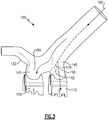
- Figure 3 schematically illustrates an alternate view of the impingement manifold 100 of Figure 2 .
- the manifold 100 also acts as a controller for the passage of spent impingement air, and facilitates the operation of an ACC system.
- the example manifold 100 includes a cylindrical inlet 120 that feeds into a manifold body 160.
- the manifold body 160 is defined by four lobes 150, each of which is connected to a radially inward impingement cavity 110 by an opening.
- a cylindrical outlet 130 curves upward from the manifold body 160 and provides an alternative fluid outlet from the manifold body 160.
- Within each of the lobes 150 is a dimple 140.
- the dimples 140 are curved inward protrusions into the interior of the lobe 150.
- Each lobe 150 also includes an outward bulge 142.
- the bulges 142 are outward protrusions from the interior of the lobe 150.
- the outlet 130 is connected to the manifold body 160 via a radially outward curvature including a bulge 132.
- the bulge 132 is similar in form and function to the bulges 142 included on each of the lobes 140.
- the combination of the dimples 140 and the bulges 142 operates to define a curvature along the interior surface of the manifold body 160 that exerts a total curvature onto flow through the manifold 100 in the range of 35 to 55 degrees. In some examples the curvature is limited to approximately 45 degrees.
- the interior surface of the manifold body 160 achieves this curvature via a continuous interior surface.
- the interior surface includes no angled junctions of 90 degrees or greater.
- the interior curvature of the manifold is defined as a ratio of the radius of curvature to the width of the manifold 100 at the curvature. In order to achieve the desired bend in the range of 35 to 55 degrees, the ratio of the radius to the width is greater than or equal to 2 and less than or equal to three along the entire interior surface of the manifold 100. In some examples, the ratio within the range of 2 to 3 is localized at each of the lobes 150, dimples 140 and bulges 142. In other examples, the ratio within the range of 2 to 3 is extended across the entire interior surface of the manifold.
- cooling air follows a flow path 102 from the inlet 120 and splits into multiple flows 104 such that the flows 104 are directed radially inward into an impingement cavity 110 of one or more shrouds through a corresponding lobe 150.
- the impingement cavities 110 in turn generate multiple impingement streams 106 that impinge upon and cool the air seal segments (not pictured).
- the spent impingement air is then released into the primary flowpath through stator flanges.
- the seal segments radially inward of the impingement cavities 110 are in some examples, attached to a thermally efficient internal flow structure that is also cooled inside by air from the fan or compressor.
- the seal segments also purge cooling air through the leading and trailing edges of the shroud segments. Since the pressure in the blade tip clearance region varies axially from the leading to trailing edge, a positive backflow margin in pressure is maintained by an engine controller to achieve this purge flow.
- the dimples 140 and bulges 142 described above are included in the forward and leeward walls of each lobe 150 of the manifold 100.
- the dimples 140 and bulges 142 improve the flow performance of cooling air being provided through the impingement manifold 100 by reducing a vorticity of the cooling air passing through the manifold body 160 relative to a manifold without the dimples 140 and bulges 142.
- the decreased vorticity improves performance of the ACC system.
- Each of the dimples 140 turns the flow 104 entering the corresponding lobe 150 with minimum pressure loss and provides a uniform ejection of the impingement air into the impingement cavities 110.
- the cooling flow paths 102, 104 branch from the inlet 120 flow path 102 to the lobe flows 104 and the interior surface defined by the lobes 150, dimples 140 and bulges 142 turn the air flows 104 in the forward portion (relative to airflow through the impingement manifold 100) towards the radially inward portion of the forward lobes 104 onto the case.
- Flow non-uniformities in the branching region (the area of the manifold body 160 where the lobes 150 branch out) generate recirculation downstream in the lobe flows 104.
- the dimples 140 impact the direction of the flows 104, by causing the flows 104 to turn less sharply.
- the airflow turns are in the range of 35-55 degrees.
- the dimples cause the airflow turns to be approximately 45 degree turns.
- the reduction in the sharpness of the airflow turns is relative to the airflow in a correspondingly shaped manifold that omits the dimples 140, and bulges 142.
- the reduced sharpness of the turns results in a fluid velocity field that is locally irrotational.
- Irrotational flows are idealized flows where losses due to vorticity are minimized.
- the irrotational flows produced by the dimples 140 and the lobes 150 also reduces a flow path 102 velocity coming from the inlet 120 by pinching the flow towards the lobes 150, resulting in more uniform flow at the outlets connecting the lobes 150 to the impingement cavities 110.
- the bulge 142 in each lobe 150 sets a compensating or contrary momentum to the radially inward flow.
- the outlet 130 also includes a bulge 132 as the outlet is turned radially outward. This keeps the flow of the fluid attached and to reduce the velocity in front of the outlet.
- the manifold 100 is, in some examples, created utilizing an additive manufacturing process.
- the additive manufacturing process can be any process including direct metal laser sintering (DMLS), or any similar construction technique. While some additive manufacturing systems can create a distinct stair step surface roughness, such a feature is sufficiently small scale that the roughness is not considered to break the continuousness of the interior surface.
- the manifold 100 can be created using a sheet metal forming procedure such as hydroforming.
- the manifold 100 can be constructed utilizing a casting technique.
- the curvature defined in the illustrated example includes localized turning within the range of 35-55 degrees or approximately 45 degrees.
- One of skill in the art, having the benefit of this disclosure will understand that lower curvatures, and in some cases higher curvatures of less than 90 degrees, can achieve similar functions and could be designed in a similar fashion. As such, it is within the contemplation of this disclosure to utilize curvatures outside of the range of 35-55 degrees, and the enumerated ranges are only exemplary in nature.
- a localized turning angle 170 is illustrated in Figure 3 , and is the angle that the fluid flow 102 turns at any given bend. Localized turning can, alternatively, be referred to as altering a direction of flow through the manifold 100.
Abstract
Description
- The present disclosure relates generally to impingement manifolds, and more specifically to gas turbine engine impingement manifolds including specialized flow features.
- Gas turbine engines include a compressor that compresses air, a combustor that ignites the compressed air and a turbine across which the compressed air is expanded. The expansion of the combustion products drives the turbine to rotate, which in turn drives rotation of the compressor. In some examples a fan is included forward of the compressor section, and driven to rotate by the turbine as well.
- In order to ensure maximized efficiency of the gas turbine engine, a clearance between the tips of rotors in the primary flowpath and an inner diameter of the primary flowpath is kept sufficiently small that a minimum amount of air passes between the tip of the rotor and the outer diameter of the flowpath, while still allowing sufficient space that the tip of the rotor does not contact the outer diameter.
- In one aspect, an impingement manifold includes a fluid inlet passage, a pressurized chamber including at least one lobe, the at least one lobe including a flow improving feature configured to minimize vorticity of a flow field within the pressurized chamber, and at least one flow outlet.
- In an embodiment of the above described impingement manifold the flow improving feature is at least one of an inward protruding dimple and an outward protruding bulge in at least one wall defining the at least one lobe.
- In another exemplary embodiment of any of the above described impingement manifolds the at least one flow outlet has a first cross sectional area normal to an expected direction of fluid flow, and the fluid inlet passage has a second cross sectional area normal to an expected direction of fluid flow, and wherein the first cross sectional area is less than the second cross sectional area.
- In another exemplary embodiment of any of the above described impingement manifolds the at least one lobe includes a plurality of lobes and each of the lobes in the plurality of lobes includes a pressurized fluid outlet.
- In another exemplary embodiment of any of the above described impingement manifolds the plurality of lobes includes four lobes.
- In another exemplary embodiment of any of the above described impingement manifolds the plurality of lobes includes three lobes.
- In another exemplary embodiment of any of the above described impingement manifolds an interior surface of the manifold is a continuous interior surface.
- In another exemplary embodiment of any of the above described impingement manifolds the continuous interior surface is configured to alter a direction of flow through the manifold by an angle within the range of 35-55 degrees.
- In another exemplary embodiment of any of the above described impingement manifolds the continuous interior surface is configured to alter a direction of flow through the manifold by an angle of approximately 45 degrees.
- In another exemplary embodiment of any of the above described impingement manifolds wherein the manifold is a single piece constructed via one of an additive manufacturing process and a casting process.
- In another exemplary embodiment of any of the above described impingement manifolds the manifold is constructed at least partially of joined shaped sheet metal pieces.
- In another exemplary embodiment of any of the above described impingement manifolds a ratio of the radius of curvature to a width of the pressurized chamber at the curvature is within the range of 2 to 3 for at least a portion of an interior surface of the pressurized chamber.
- In another aspect, a method for providing a cooling flow to an aircraft component includes passing a cooling flow through a manifold including a pressurized chamber having at least one lobe including a flow improving feature configured to minimize vorticity of a flow field within the pressurized chamber.
- In an example of the above described method for providing cooling flow to an aircraft component passing the cooling flow through the manifold further comprises turning the fluid flow less than 55 degrees.
- In a further example of any of the above described exemplary methods for providing cooling flow to an aircraft component passing the cooling flow through the manifold further comprises turning the fluid flow within the range of 35-55 degrees.
- In a further example of any of the above described exemplary methods for providing cooling flow to an aircraft component passing the cooling flow through the manifold, includes directing the cooling flow using a continuous interior surface of the manifold.
- In a further example of any of the above described exemplary methods for providing cooling flow to an aircraft component passing the cooling flow through the manifold includes passing the cooling flow through at least one of a plurality of lobes.
- In a further example of any of the above described exemplary methods for providing cooling flow to an aircraft component passing the cooling flow through the manifold includes splitting the cooling flow, such that a portion of the cooling flow is passed through each lobe in the plurality of lobes.
- In another aspect, a gas turbine engine includes a compressor section partially defining a primary flowpath, a combustor section fluidly connected to the compressor section and partially defining the primary flowpath, a turbine section fluidly connected to the combustor section and partially defining the primary flowpath, and a fluid manifold including a continuous interior surface.
- The fluid manifold may comprise any of the features described above and/or claimed in claims 1 to 9.
- In an exemplary embodiment of the above described gas turbine engine the fluid manifold is a component of an active clearance control system configured radially outward of at least one of a compressor stage and a turbine stage, and wherein the fluid manifold includes a fluid inlet passage, a pressurized chamber including at least one lobe, the at least one lobe including a flow improving feature configured to minimize vorticity of a flow field within the pressurized chamber, and at least one flow outlet.
- These and other features of the present invention can be best understood from the following specification and drawings, the following of which is a brief description.
-
-
Figure 1 schematically illustrates an exemplary gas turbine engine. -
Figure 2 schematically illustrates an example impingement manifold. -
Figure 3 schematically illustrates an alternate view of the example impingement manifold ofFigure 2 . -
Figure 1 schematically illustrates agas turbine engine 20. Thegas turbine engine 20 is disclosed herein as a two-spool turbofan that generally incorporates afan section 22, acompressor section 24, acombustor section 26 and aturbine section 28. Alternative engines might include an augmentor section (not shown) among other systems or features. Thefan section 22 drives air along a bypass flow path B in a bypass duct defined within a nacelle 15, while thecompressor section 24 drives air along a core flow path C for compression and communication into thecombustor section 26 then expansion through theturbine section 28. Although depicted as a two-spool turbofan gas turbine engine in the disclosed non-limiting embodiment, it should be understood that the concepts described herein are not limited to use with two-spool turbofans as the teachings may be applied to other types of turbine engines including three-spool architectures. - The
exemplary engine 20 generally includes alow speed spool 30 and ahigh speed spool 32 mounted for rotation about an engine central longitudinal axis A relative to an enginestatic structure 36 viaseveral bearing systems 38. It should be understood thatvarious bearing systems 38 at various locations may alternatively or additionally be provided, and the location ofbearing systems 38 may be varied as appropriate to the application. - The
low speed spool 30 generally includes aninner shaft 40 that interconnects afan 42, a first (or low)pressure compressor 44 and a first (or low)pressure turbine 46. Theinner shaft 40 is connected to thefan 42 through a speed change mechanism, which in exemplarygas turbine engine 20 is illustrated as a gearedarchitecture 48 to drive thefan 42 at a lower speed than thelow speed spool 30. Thehigh speed spool 32 includes anouter shaft 50 that interconnects a second (or high)pressure compressor 52 and a second (or high)pressure turbine 54. Acombustor 56 is arranged inexemplary gas turbine 20 between thehigh pressure compressor 52 and thehigh pressure turbine 54. Amid-turbine frame 57 of the enginestatic structure 36 is arranged generally between thehigh pressure turbine 54 and thelow pressure turbine 46. Themid-turbine frame 57 further supports bearingsystems 38 in theturbine section 28. Theinner shaft 40 and theouter shaft 50 are concentric and rotate viabearing systems 38 about the engine central longitudinal axis A which is collinear with their longitudinal axes. - The core airflow is compressed by the
low pressure compressor 44 then thehigh pressure compressor 52, mixed and burned with fuel in thecombustor 56, then expanded over thehigh pressure turbine 54 andlow pressure turbine 46. Themid-turbine frame 57 includes airfoils which are in the core airflow path C. Theturbines low speed spool 30 andhigh speed spool 32 in response to the expansion. It will be appreciated that each of the positions of thefan section 22,compressor section 24,combustor section 26,turbine section 28, and fandrive gear system 48 may be varied. For example,gear system 48 may be located aft ofcombustor section 26 or even aft ofturbine section 28, andfan section 22 may be positioned forward or aft of the location ofgear system 48. - The
engine 20 in one example is a high-bypass geared aircraft engine. In a further example, theengine 20 bypass ratio is greater than about six, with an example embodiment being greater than about ten, the gearedarchitecture 48 is an epicyclic gear train, such as a planetary gear system or other gear system, with a gear reduction ratio of greater than about 2.3 and thelow pressure turbine 46 has a pressure ratio that is greater than about five. In one disclosed embodiment, theengine 20 bypass ratio is greater than about ten, the fan diameter is significantly larger than that of thelow pressure compressor 44, and thelow pressure turbine 46 has a pressure ratio that is greater than about five.Low pressure turbine 46 pressure ratio is pressure measured prior to inlet oflow pressure turbine 46 as related to the pressure at the outlet of thelow pressure turbine 46 prior to an exhaust nozzle. The gearedarchitecture 48 may be an epicycle gear train, such as a planetary gear system or other gear system, with a gear reduction ratio of greater than about 2.3:1. It should be understood, however, that the above parameters are only exemplary of one embodiment of a geared architecture engine and that the present invention is applicable to other gas turbine engines including direct drive turbofans. - A significant amount of thrust is provided by the bypass flow B due to the high bypass ratio. The
fan section 22 of theengine 20 is designed for a particular flight condition -- typically cruise at about 0.8 Mach and about 35,000 feet (10668 meters). The flight condition of 0.8 Mach and 35,000 ft (10668 m), with the engine at its best fuel consumption - also known as "bucket cruise Thrust Specific Fuel Consumption ('TSFC')" - is the industry standard parameter of lbm of fuel being burned divided by lbf of thrust the engine produces at that minimum point. "Low fan pressure ratio" is the pressure ratio across the fan blade alone, without a Fan Exit Guide Vane ("FEGV") system. The low fan pressure ratio as disclosed herein according to one non-limiting embodiment is less than about 1.45. "Low corrected fan tip speed" is the actual fan tip speed in ft/sec divided by an industry standard temperature correction of [(Tram °R) / (518.7 °R)]^0.5 (where °R = K x 9/5). The "Low corrected fan tip speed" as disclosed herein according to one non-limiting embodiment is less than about 1150 ft / second (350.5 m/s). - The engine efficiency, fuel consumption, payload, range, and stall margin of gas turbine engines, such as the
gas turbine engine 20 illustrated inFigure 1 , is improved by minimizing the amount of leakage of air that occurs within thecompressor section 24 and theturbine section 28. Leakage air within thecompressor section 24 or theturbine section 28 is air that passes between a radially outward rotor tip and an outer diameter of the primary flowpath. Leakage air does not contribute to the power extracted by the turbine and results in an overall loss of efficiency. The loss of efficiency due to leakage air, which increases as the engine is operated over time, leads to decreased engine service life, less time on wing, greater degradation of engine components, increased maintenance costs, and reduction of exhaust gas temperature margin. - Outer air seals in gas turbine engines form containing shrouds around the rotors. The distance between the case, air seal and the tips of the turbine blades is referred to as the tip clearance. The tip clearance is typically minimized in order to limit the leakage air. However, the tip clearance is maintained large enough to avoid contact between the rotor tips and the shroud. During operation of the
gas turbine engine 20, the clearance between blade tips and the surrounding case, or shroud, varies due to thermo-mechanical loads on the rotating and stationary structures. The magnitude of the tip clearance varies over multiple operating points (take-off, climb, cruise, descent, re-accel, etc.) of the engine as distortion and displacement is caused by the centrifugal, thermal and pressure loads on both the rotating and the static components in the engine. - In order to minimize leakage losses during transient engine operation, interstage sealing and blade tip clearance control are used in gas turbine engines. Some gas turbine engines include active clearance control (ACC) systems that improve turbine and compressor blade tip clearances. ACC systems maintain minimum tip clearance during cruise, while avoiding rubs (contact between a blade tip and an outer diameter of the flowpath) over the flight profile. ACC includes active thermal maintenance of one or more aircraft parts.
- Some example active thermal maintenance systems utilize cooling air to cool outer air seal segments within a shroud. The cooling of the outer air seal segments results in thermal shrinkage. The thermal shrinkage, in turn, closes the gap between the blades and the shroud by contracting the case. If the clearance is required to be increased, the cooling air is reduced or removed.
-
Figure 2 schematically illustrates anexample impingement manifold 100 that acts as a cooling air collector and air flow splitter to provide cooling air to impingementcavities 110 within a shroud and impinges the cooling air on a blade outer air seal (not pictured, radially inward of theimpingement cavity 110.Figure 3 schematically illustrates an alternate view of theimpingement manifold 100 ofFigure 2 . The manifold 100 also acts as a controller for the passage of spent impingement air, and facilitates the operation of an ACC system. - The
example manifold 100 includes acylindrical inlet 120 that feeds into amanifold body 160. Themanifold body 160 is defined by fourlobes 150, each of which is connected to a radiallyinward impingement cavity 110 by an opening. Acylindrical outlet 130 curves upward from themanifold body 160 and provides an alternative fluid outlet from themanifold body 160. Within each of thelobes 150 is adimple 140. Thedimples 140 are curved inward protrusions into the interior of thelobe 150. Eachlobe 150 also includes anoutward bulge 142. Thebulges 142 are outward protrusions from the interior of thelobe 150. Theoutlet 130 is connected to themanifold body 160 via a radially outward curvature including abulge 132. Thebulge 132 is similar in form and function to thebulges 142 included on each of thelobes 140. The combination of thedimples 140 and thebulges 142 operates to define a curvature along the interior surface of themanifold body 160 that exerts a total curvature onto flow through the manifold 100 in the range of 35 to 55 degrees. In some examples the curvature is limited to approximately 45 degrees. - The interior surface of the
manifold body 160 achieves this curvature via a continuous interior surface. In other words, barring manufacturing roughness, the interior surface includes no angled junctions of 90 degrees or greater. The interior curvature of the manifold is defined as a ratio of the radius of curvature to the width of the manifold 100 at the curvature. In order to achieve the desired bend in the range of 35 to 55 degrees, the ratio of the radius to the width is greater than or equal to 2 and less than or equal to three along the entire interior surface of themanifold 100. In some examples, the ratio within the range of 2 to 3 is localized at each of thelobes 150,dimples 140 and bulges 142. In other examples, the ratio within the range of 2 to 3 is extended across the entire interior surface of the manifold. - In an example implementation, cooling air follows a
flow path 102 from theinlet 120 and splits intomultiple flows 104 such that theflows 104 are directed radially inward into animpingement cavity 110 of one or more shrouds through acorresponding lobe 150. The impingement cavities 110 in turn generatemultiple impingement streams 106 that impinge upon and cool the air seal segments (not pictured). The spent impingement air is then released into the primary flowpath through stator flanges. - The seal segments radially inward of the
impingement cavities 110 are in some examples, attached to a thermally efficient internal flow structure that is also cooled inside by air from the fan or compressor. In some examples, the seal segments also purge cooling air through the leading and trailing edges of the shroud segments. Since the pressure in the blade tip clearance region varies axially from the leading to trailing edge, a positive backflow margin in pressure is maintained by an engine controller to achieve this purge flow. - The
dimples 140 and bulges 142 described above are included in the forward and leeward walls of eachlobe 150 of themanifold 100. Thedimples 140 and bulges 142 improve the flow performance of cooling air being provided through theimpingement manifold 100 by reducing a vorticity of the cooling air passing through themanifold body 160 relative to a manifold without thedimples 140 and bulges 142. The decreased vorticity improves performance of the ACC system. - Each of the
dimples 140 turns theflow 104 entering thecorresponding lobe 150 with minimum pressure loss and provides a uniform ejection of the impingement air into theimpingement cavities 110. Thecooling flow paths inlet 120flow path 102 to the lobe flows 104 and the interior surface defined by thelobes 150,dimples 140 and bulges 142 turn the air flows 104 in the forward portion (relative to airflow through the impingement manifold 100) towards the radially inward portion of theforward lobes 104 onto the case. - Flow non-uniformities in the branching region (the area of the
manifold body 160 where thelobes 150 branch out) generate recirculation downstream in the lobe flows 104. Thedimples 140 impact the direction of theflows 104, by causing theflows 104 to turn less sharply. In some examples the airflow turns are in the range of 35-55 degrees. In alternative examples, the dimples cause the airflow turns to be approximately 45 degree turns. The reduction in the sharpness of the airflow turns is relative to the airflow in a correspondingly shaped manifold that omits thedimples 140, and bulges 142. - The reduced sharpness of the turns results in a fluid velocity field that is locally irrotational. Irrotational flows are idealized flows where losses due to vorticity are minimized. The irrotational flows produced by the
dimples 140 and thelobes 150 also reduces aflow path 102 velocity coming from theinlet 120 by pinching the flow towards thelobes 150, resulting in more uniform flow at the outlets connecting thelobes 150 to theimpingement cavities 110. Thebulge 142 in eachlobe 150 sets a compensating or contrary momentum to the radially inward flow. Theoutlet 130 also includes abulge 132 as the outlet is turned radially outward. This keeps the flow of the fluid attached and to reduce the velocity in front of the outlet. - In order to construct the
bulges lobes 150, of theoverall manifold 100, as well as to reduce internal features that would induce vortices in the fluid flow through the manifold 100, the manifold 100 is, in some examples, created utilizing an additive manufacturing process. The additive manufacturing process can be any process including direct metal laser sintering (DMLS), or any similar construction technique. While some additive manufacturing systems can create a distinct stair step surface roughness, such a feature is sufficiently small scale that the roughness is not considered to break the continuousness of the interior surface. In alternative examples, particularly those with consecutive series oriented lobes, the manifold 100 can be created using a sheet metal forming procedure such as hydroforming. In yet further alternatives, depending on the specific features of the manifold, the manifold 100 can be constructed utilizing a casting technique. - While discussed above within the specific context of an
impingement manifold 100 for an ACC system, one of ordinary skill in the art, having the benefit of this disclosure will understand that the utilization of organic interior curvature, such as dimples and bulges, as well as the lobed construction, can facilitate cooling fluid flow through manifolds for multiple distinct purposes, and is not limited to an ACC impingement manifold. - The curvature defined in the illustrated example includes localized turning within the range of 35-55 degrees or approximately 45 degrees. One of skill in the art, having the benefit of this disclosure will understand that lower curvatures, and in some cases higher curvatures of less than 90 degrees, can achieve similar functions and could be designed in a similar fashion. As such, it is within the contemplation of this disclosure to utilize curvatures outside of the range of 35-55 degrees, and the enumerated ranges are only exemplary in nature. By way of example, a
localized turning angle 170 is illustrated inFigure 3 , and is the angle that thefluid flow 102 turns at any given bend. Localized turning can, alternatively, be referred to as altering a direction of flow through themanifold 100. - It is further understood that any of the above described concepts can be used alone or in combination with any or all of the other above described concepts. Although an embodiment of this invention has been disclosed, a worker of ordinary skill in this art would recognize that certain modifications would come within the scope of this invention. For that reason, the following claims should be studied to determine the true scope and content of this invention.
Claims (15)
- An impingement manifold (100) comprising:a fluid inlet passage (120);a pressurized chamber (160) including at least one lobe (150), the at least one lobe (150) including a flow improving feature (140, 142) configured to minimize vorticity of a flow field within the pressurized chamber (160); andat least one flow outlet (130).
- The impingement manifold (100) of claim 1, wherein the flow improving feature (140, 142) comprises an inward protruding dimple (140) and/or an outward protruding bulge (142) in at least one wall defining the at least one lobe (150).
- The impingement manifold (100) of claim 1 or 2, wherein the at least one flow outlet (130) has a first cross sectional area normal to an expected direction of fluid flow, the fluid inlet passage (120) has a second cross sectional area normal to an expected direction of fluid flow, and the first cross sectional area is less than the second cross sectional area.
- The impingement manifold (100) of claim 1, 2 or 3, wherein the at least one lobe (150) includes a plurality of lobes (150) and each of the lobes (150) in the plurality of lobes (150) includes a pressurized fluid outlet (130), optionally wherein the plurality of lobes includes four lobes, or three lobes.
- The impingement manifold (100) of any preceding claim, wherein an interior surface of said manifold (100) is a continuous interior surface.
- The impingement manifold (100) of claim 5, wherein said continuous interior surface is configured to alter a direction of flow through the manifold (100) by an angle (170) within the range of 35-55 degrees, optionally wherein said continuous interior surface is configured to alter a direction of flow through the manifold by an angle (170) of approximately 45 degrees.
- The impingement manifold (100) of any preceding claim, wherein the manifold (100) is a single piece constructed via one of an additive manufacturing process and a casting process.
- The impingement manifold (100) of any of claims 1 to 6, wherein the manifold (100) is constructed at least partially of joined shaped sheet metal pieces.
- The impingement manifold (100) of any preceding claim, wherein a ratio of the radius of curvature to a width of the pressurized chamber (160) at the curvature is within the range of 2 to 3 for at least a portion of an interior surface of the pressurized chamber (160).
- A method for providing a cooling flow to an aircraft component comprising passing a cooling flow through a manifold (100) including a pressurized chamber (160) having at least one lobe (150) including a flow improving feature (140, 142) configured to minimize vorticity of a flow field within the pressurized chamber (160).
- The method of claim 10, wherein passing the cooling flow through the manifold (100) further comprises turning the fluid flow less than 55 degrees, optionally within the range of 35-55 degrees.
- The method of claim 10 or 11, wherein passing the cooling flow through the manifold (100) includes directing the cooling flow using a continuous interior surface of the manifold (100).
- The method of claim 10, 11 or 12, wherein passing the cooling flow through the manifold (100) includes passing the cooling flow through at least one of a plurality of lobes (150), optionally splitting the cooling flow, such that a portion of the cooling flow is passed through each lobe (150) in said plurality of lobes (150).
- A gas turbine engine (20) comprising:a compressor section (24) partially defining a primary flowpath;a combustor section (26) fluidly connected to the compressor section (24) and partially defining the primary flowpath;a turbine section (28) fluidly connected to the combustor section (26) and partially defining the primary flowpath; anda fluid manifold (100) including a continuous interior surface.
- The gas turbine engine (20) of claim 14, wherein the fluid manifold (100) is a component of an active clearance control system configured radially outward of at least one of a compressor stage and a turbine stage, and the fluid manifold (100) includes a fluid inlet passage (120), a pressurized chamber (160) including at least one lobe (150), the at least one lobe (150) including a flow improving feature (140, 142) configured to minimize vorticity of a flow field within the pressurized chamber (160), and at least one flow outlet (130).
Applications Claiming Priority (1)
| Application Number | Priority Date | Filing Date | Title |
|---|---|---|---|
| US15/148,336 US10329941B2 (en) | 2016-05-06 | 2016-05-06 | Impingement manifold |
Publications (2)
| Publication Number | Publication Date |
|---|---|
| EP3246524A1 true EP3246524A1 (en) | 2017-11-22 |
| EP3246524B1 EP3246524B1 (en) | 2019-09-18 |
Family
ID=58692414
Family Applications (1)
| Application Number | Title | Priority Date | Filing Date |
|---|---|---|---|
| EP17169950.7A Active EP3246524B1 (en) | 2016-05-06 | 2017-05-08 | Impingement manifold |
Country Status (2)
| Country | Link |
|---|---|
| US (1) | US10329941B2 (en) |
| EP (1) | EP3246524B1 (en) |
Families Citing this family (4)
| Publication number | Priority date | Publication date | Assignee | Title |
|---|---|---|---|---|
| US10329941B2 (en) * | 2016-05-06 | 2019-06-25 | United Technologies Corporation | Impingement manifold |
| US20190170009A1 (en) * | 2017-12-05 | 2019-06-06 | General Electric Company | Turbine engine with clearance control system |
| FR3085719B1 (en) * | 2018-09-06 | 2021-04-16 | Safran Aircraft Engines | PRESSURIZED AIR SUPPLY BOX OF AN AIR JET COOLING DEVICE |
| US11015475B2 (en) | 2018-12-27 | 2021-05-25 | Rolls-Royce Corporation | Passive blade tip clearance control system for gas turbine engine |
Citations (5)
| Publication number | Priority date | Publication date | Assignee | Title |
|---|---|---|---|---|
| US5100291A (en) * | 1990-03-28 | 1992-03-31 | General Electric Company | Impingement manifold |
| US6487491B1 (en) * | 2001-11-21 | 2002-11-26 | United Technologies Corporation | System and method of controlling clearance between turbine engine blades and case based on engine components thermal growth model |
| EP1473518A2 (en) * | 2003-04-28 | 2004-11-03 | General Electric Company | Methods and apparatus for injecting fluids in gas turbine engines |
| EP2226473A2 (en) * | 2009-03-04 | 2010-09-08 | Rolls-Royce Deutschland Ltd & Co KG | Air guiding element of a system for tip clearance adjustment of an aero gas turbine |
| WO2014186002A2 (en) * | 2013-04-12 | 2014-11-20 | United Technologies Corporation | Rapid response clearance control system with spring assist for gas turbine engine |
Family Cites Families (37)
| Publication number | Priority date | Publication date | Assignee | Title |
|---|---|---|---|---|
| US2698711A (en) * | 1951-02-06 | 1955-01-04 | United Aircraft Corp | Compressor air bleed closure |
| US4155681A (en) * | 1977-02-14 | 1979-05-22 | General Electric Company | Manifold protection system |
| US4329114A (en) * | 1979-07-25 | 1982-05-11 | The United States Of America As Represented By The Administrator Of The National Aeronautics And Space Administration | Active clearance control system for a turbomachine |
| DE3407945A1 (en) * | 1984-03-03 | 1985-09-05 | MTU Motoren- und Turbinen-Union München GmbH, 8000 München | METHOD AND MEANS FOR AVOIDING THE DEVELOPMENT OF TITANIUM FIRE |
| US4642024A (en) | 1984-12-05 | 1987-02-10 | United Technologies Corporation | Coolable stator assembly for a rotary machine |
| US4650395A (en) | 1984-12-21 | 1987-03-17 | United Technologies Corporation | Coolable seal segment for a rotary machine |
| US5092735A (en) * | 1990-07-02 | 1992-03-03 | The United States Of America As Represented By The Secretary Of The Air Force | Blade outer air seal cooling system |
| US5116199A (en) * | 1990-12-20 | 1992-05-26 | General Electric Company | Blade tip clearance control apparatus using shroud segment annular support ring thermal expansion |
| US5281085A (en) | 1990-12-21 | 1994-01-25 | General Electric Company | Clearance control system for separately expanding or contracting individual portions of an annular shroud |
| WO1992017686A1 (en) * | 1991-04-02 | 1992-10-15 | Rolls-Royce Plc | Turbine casing |
| US5399066A (en) * | 1993-09-30 | 1995-03-21 | General Electric Company | Integral clearance control impingement manifold and environmental shield |
| FR2750451B1 (en) * | 1996-06-27 | 1998-08-07 | Snecma | DEVICE FOR BLOWING GAS ADJUSTING GAMES IN A TURBOMACHINE |
| GB9709086D0 (en) * | 1997-05-07 | 1997-06-25 | Rolls Royce Plc | Gas turbine engine cooling apparatus |
| US6367240B1 (en) * | 1998-06-22 | 2002-04-09 | General Electric Company | Air manifold system |
| US6224329B1 (en) * | 1999-01-07 | 2001-05-01 | Siemens Westinghouse Power Corporation | Method of cooling a combustion turbine |
| US6185925B1 (en) * | 1999-02-12 | 2001-02-13 | General Electric Company | External cooling system for turbine frame |
| FR2816352B1 (en) * | 2000-11-09 | 2003-01-31 | Snecma Moteurs | VENTILATION ASSEMBLY OF A STATOR RING |
| US7082770B2 (en) | 2003-12-24 | 2006-08-01 | Martling Vincent C | Flow sleeve for a low NOx combustor |
| FR2867806B1 (en) * | 2004-03-18 | 2006-06-02 | Snecma Moteurs | DEVICE FOR CONTROLLING GAS TURBINE SET WITH AIR FLOW BALANCING |
| US7513040B2 (en) | 2005-08-31 | 2009-04-07 | United Technologies Corporation | Manufacturable and inspectable cooling microcircuits for blade-outer-air-seals |
| US7597537B2 (en) * | 2005-12-16 | 2009-10-06 | General Electric Company | Thermal control of gas turbine engine rings for active clearance control |
| US7819626B2 (en) * | 2006-10-13 | 2010-10-26 | General Electric Company | Plasma blade tip clearance control |
| US8439629B2 (en) | 2007-03-01 | 2013-05-14 | United Technologies Corporation | Blade outer air seal |
| US8439639B2 (en) | 2008-02-24 | 2013-05-14 | United Technologies Corporation | Filter system for blade outer air seal |
| GB0904118D0 (en) * | 2009-03-11 | 2009-04-22 | Rolls Royce Plc | An impingement cooling arrangement for a gas turbine engine |
| US8092146B2 (en) * | 2009-03-26 | 2012-01-10 | Pratt & Whitney Canada Corp. | Active tip clearance control arrangement for gas turbine engine |
| GB0906059D0 (en) * | 2009-04-08 | 2009-05-20 | Rolls Royce Plc | Thermal control system for turbines |
| US8622693B2 (en) | 2009-08-18 | 2014-01-07 | Pratt & Whitney Canada Corp | Blade outer air seal support cooling air distribution system |
| US8769954B2 (en) * | 2009-12-31 | 2014-07-08 | General Electric Company | Frequency-tunable bracketless fluid manifold |
| GB201020418D0 (en) * | 2010-12-02 | 2011-01-19 | Rolls Royce Plc | Fluid impingement arrangement |
| US9316111B2 (en) * | 2011-12-15 | 2016-04-19 | Pratt & Whitney Canada Corp. | Active turbine tip clearance control system |
| US9260974B2 (en) * | 2011-12-16 | 2016-02-16 | General Electric Company | System and method for active clearance control |
| US9316155B2 (en) * | 2013-03-18 | 2016-04-19 | General Electric Company | System for providing fuel to a combustor |
| US8910470B2 (en) * | 2013-05-17 | 2014-12-16 | Ford Global Technologies, Llc | Exhaust system having a flow rotation element and method for operation of an exhaust system |
| US20170114667A1 (en) * | 2015-10-23 | 2017-04-27 | General Electric Company | Active clearance control with integral double wall heat shielding |
| US10087772B2 (en) * | 2015-12-21 | 2018-10-02 | General Electric Company | Method and apparatus for active clearance control for high pressure compressors using fan/booster exhaust air |
| US10329941B2 (en) * | 2016-05-06 | 2019-06-25 | United Technologies Corporation | Impingement manifold |
-
2016
- 2016-05-06 US US15/148,336 patent/US10329941B2/en active Active
-
2017
- 2017-05-08 EP EP17169950.7A patent/EP3246524B1/en active Active
Patent Citations (5)
| Publication number | Priority date | Publication date | Assignee | Title |
|---|---|---|---|---|
| US5100291A (en) * | 1990-03-28 | 1992-03-31 | General Electric Company | Impingement manifold |
| US6487491B1 (en) * | 2001-11-21 | 2002-11-26 | United Technologies Corporation | System and method of controlling clearance between turbine engine blades and case based on engine components thermal growth model |
| EP1473518A2 (en) * | 2003-04-28 | 2004-11-03 | General Electric Company | Methods and apparatus for injecting fluids in gas turbine engines |
| EP2226473A2 (en) * | 2009-03-04 | 2010-09-08 | Rolls-Royce Deutschland Ltd & Co KG | Air guiding element of a system for tip clearance adjustment of an aero gas turbine |
| WO2014186002A2 (en) * | 2013-04-12 | 2014-11-20 | United Technologies Corporation | Rapid response clearance control system with spring assist for gas turbine engine |
Also Published As
| Publication number | Publication date |
|---|---|
| US20170321568A1 (en) | 2017-11-09 |
| EP3246524B1 (en) | 2019-09-18 |
| US10329941B2 (en) | 2019-06-25 |
Similar Documents
| Publication | Publication Date | Title |
|---|---|---|
| US11661865B2 (en) | Gas turbine engine component | |
| US9920633B2 (en) | Compound fillet for a gas turbine airfoil | |
| US10036271B2 (en) | Gas turbine engine blade outer air seal profile | |
| US10830070B2 (en) | Endwall countouring trench | |
| US9476308B2 (en) | Gas turbine engine serpentine cooling passage with chevrons | |
| EP3063374A1 (en) | Gas turbine engine airfoil with auxiliary flow channel | |
| EP3246524B1 (en) | Impingement manifold | |
| US10309253B2 (en) | Gas turbine engine blade outer air seal profile | |
| US20160208620A1 (en) | Gas turbine engine airfoil turbulator for airfoil creep resistance | |
| EP3351731A1 (en) | Trailing edge configuration with cast slots and drilled filmholes | |
| US20160102561A1 (en) | Gas turbine engine turbine blade tip cooling | |
| US20140219813A1 (en) | Gas turbine engine serpentine cooling passage | |
| EP2993303B1 (en) | Gas turbine engine component with film cooling hole with pocket | |
| EP3023596B1 (en) | Internally cooled turbine platform | |
| EP3623587B1 (en) | Airfoil assembly for a gas turbine engine | |
| EP3623585B1 (en) | Pressure side cover for a variable camber vane assembly for a compressor of a gas turbine engine |
Legal Events
| Date | Code | Title | Description |
|---|---|---|---|
| PUAI | Public reference made under article 153(3) epc to a published international application that has entered the european phase |
Free format text: ORIGINAL CODE: 0009012 |
|
| STAA | Information on the status of an ep patent application or granted ep patent |
Free format text: STATUS: THE APPLICATION HAS BEEN PUBLISHED |
|
| AK | Designated contracting states |
Kind code of ref document: A1 Designated state(s): AL AT BE BG CH CY CZ DE DK EE ES FI FR GB GR HR HU IE IS IT LI LT LU LV MC MK MT NL NO PL PT RO RS SE SI SK SM TR |
|
| AX | Request for extension of the european patent |
Extension state: BA ME |
|
| STAA | Information on the status of an ep patent application or granted ep patent |
Free format text: STATUS: REQUEST FOR EXAMINATION WAS MADE |
|
| 17P | Request for examination filed |
Effective date: 20180522 |
|
| RBV | Designated contracting states (corrected) |
Designated state(s): AL AT BE BG CH CY CZ DE DK EE ES FI FR GB GR HR HU IE IS IT LI LT LU LV MC MK MT NL NO PL PT RO RS SE SI SK SM TR |
|
| RIC1 | Information provided on ipc code assigned before grant |
Ipc: F02C 6/08 20060101ALI20180622BHEP Ipc: F01D 11/24 20060101ALI20180622BHEP Ipc: F01D 25/12 20060101ALI20180622BHEP Ipc: F01D 11/20 20060101AFI20180622BHEP |
|
| STAA | Information on the status of an ep patent application or granted ep patent |
Free format text: STATUS: EXAMINATION IS IN PROGRESS |
|
| 17Q | First examination report despatched |
Effective date: 20180808 |
|
| GRAP | Despatch of communication of intention to grant a patent |
Free format text: ORIGINAL CODE: EPIDOSNIGR1 |
|
| STAA | Information on the status of an ep patent application or granted ep patent |
Free format text: STATUS: GRANT OF PATENT IS INTENDED |
|
| INTG | Intention to grant announced |
Effective date: 20190326 |
|
| GRAS | Grant fee paid |
Free format text: ORIGINAL CODE: EPIDOSNIGR3 |
|
| GRAA | (expected) grant |
Free format text: ORIGINAL CODE: 0009210 |
|
| STAA | Information on the status of an ep patent application or granted ep patent |
Free format text: STATUS: THE PATENT HAS BEEN GRANTED |
|
| AK | Designated contracting states |
Kind code of ref document: B1 Designated state(s): AL AT BE BG CH CY CZ DE DK EE ES FI FR GB GR HR HU IE IS IT LI LT LU LV MC MK MT NL NO PL PT RO RS SE SI SK SM TR |
|
| REG | Reference to a national code |
Ref country code: GB Ref legal event code: FG4D |
|
| REG | Reference to a national code |
Ref country code: CH Ref legal event code: EP |
|
| REG | Reference to a national code |
Ref country code: DE Ref legal event code: R096 Ref document number: 602017007097 Country of ref document: DE |
|
| REG | Reference to a national code |
Ref country code: AT Ref legal event code: REF Ref document number: 1181548 Country of ref document: AT Kind code of ref document: T Effective date: 20191015 |
|
| REG | Reference to a national code |
Ref country code: IE Ref legal event code: FG4D |
|
| REG | Reference to a national code |
Ref country code: NL Ref legal event code: MP Effective date: 20190918 |
|
| PG25 | Lapsed in a contracting state [announced via postgrant information from national office to epo] |
Ref country code: HR Free format text: LAPSE BECAUSE OF FAILURE TO SUBMIT A TRANSLATION OF THE DESCRIPTION OR TO PAY THE FEE WITHIN THE PRESCRIBED TIME-LIMIT Effective date: 20190918 Ref country code: LT Free format text: LAPSE BECAUSE OF FAILURE TO SUBMIT A TRANSLATION OF THE DESCRIPTION OR TO PAY THE FEE WITHIN THE PRESCRIBED TIME-LIMIT Effective date: 20190918 Ref country code: NO Free format text: LAPSE BECAUSE OF FAILURE TO SUBMIT A TRANSLATION OF THE DESCRIPTION OR TO PAY THE FEE WITHIN THE PRESCRIBED TIME-LIMIT Effective date: 20191218 Ref country code: BG Free format text: LAPSE BECAUSE OF FAILURE TO SUBMIT A TRANSLATION OF THE DESCRIPTION OR TO PAY THE FEE WITHIN THE PRESCRIBED TIME-LIMIT Effective date: 20191218 Ref country code: FI Free format text: LAPSE BECAUSE OF FAILURE TO SUBMIT A TRANSLATION OF THE DESCRIPTION OR TO PAY THE FEE WITHIN THE PRESCRIBED TIME-LIMIT Effective date: 20190918 Ref country code: SE Free format text: LAPSE BECAUSE OF FAILURE TO SUBMIT A TRANSLATION OF THE DESCRIPTION OR TO PAY THE FEE WITHIN THE PRESCRIBED TIME-LIMIT Effective date: 20190918 |
|
| REG | Reference to a national code |
Ref country code: LT Ref legal event code: MG4D |
|
| PG25 | Lapsed in a contracting state [announced via postgrant information from national office to epo] |
Ref country code: LV Free format text: LAPSE BECAUSE OF FAILURE TO SUBMIT A TRANSLATION OF THE DESCRIPTION OR TO PAY THE FEE WITHIN THE PRESCRIBED TIME-LIMIT Effective date: 20190918 Ref country code: RS Free format text: LAPSE BECAUSE OF FAILURE TO SUBMIT A TRANSLATION OF THE DESCRIPTION OR TO PAY THE FEE WITHIN THE PRESCRIBED TIME-LIMIT Effective date: 20190918 Ref country code: GR Free format text: LAPSE BECAUSE OF FAILURE TO SUBMIT A TRANSLATION OF THE DESCRIPTION OR TO PAY THE FEE WITHIN THE PRESCRIBED TIME-LIMIT Effective date: 20191219 Ref country code: AL Free format text: LAPSE BECAUSE OF FAILURE TO SUBMIT A TRANSLATION OF THE DESCRIPTION OR TO PAY THE FEE WITHIN THE PRESCRIBED TIME-LIMIT Effective date: 20190918 |
|
| REG | Reference to a national code |
Ref country code: AT Ref legal event code: MK05 Ref document number: 1181548 Country of ref document: AT Kind code of ref document: T Effective date: 20190918 |
|
| PG25 | Lapsed in a contracting state [announced via postgrant information from national office to epo] |
Ref country code: AT Free format text: LAPSE BECAUSE OF FAILURE TO SUBMIT A TRANSLATION OF THE DESCRIPTION OR TO PAY THE FEE WITHIN THE PRESCRIBED TIME-LIMIT Effective date: 20190918 Ref country code: NL Free format text: LAPSE BECAUSE OF FAILURE TO SUBMIT A TRANSLATION OF THE DESCRIPTION OR TO PAY THE FEE WITHIN THE PRESCRIBED TIME-LIMIT Effective date: 20190918 Ref country code: EE Free format text: LAPSE BECAUSE OF FAILURE TO SUBMIT A TRANSLATION OF THE DESCRIPTION OR TO PAY THE FEE WITHIN THE PRESCRIBED TIME-LIMIT Effective date: 20190918 Ref country code: PT Free format text: LAPSE BECAUSE OF FAILURE TO SUBMIT A TRANSLATION OF THE DESCRIPTION OR TO PAY THE FEE WITHIN THE PRESCRIBED TIME-LIMIT Effective date: 20200120 Ref country code: RO Free format text: LAPSE BECAUSE OF FAILURE TO SUBMIT A TRANSLATION OF THE DESCRIPTION OR TO PAY THE FEE WITHIN THE PRESCRIBED TIME-LIMIT Effective date: 20190918 Ref country code: IT Free format text: LAPSE BECAUSE OF FAILURE TO SUBMIT A TRANSLATION OF THE DESCRIPTION OR TO PAY THE FEE WITHIN THE PRESCRIBED TIME-LIMIT Effective date: 20190918 Ref country code: PL Free format text: LAPSE BECAUSE OF FAILURE TO SUBMIT A TRANSLATION OF THE DESCRIPTION OR TO PAY THE FEE WITHIN THE PRESCRIBED TIME-LIMIT Effective date: 20190918 Ref country code: ES Free format text: LAPSE BECAUSE OF FAILURE TO SUBMIT A TRANSLATION OF THE DESCRIPTION OR TO PAY THE FEE WITHIN THE PRESCRIBED TIME-LIMIT Effective date: 20190918 |
|
| PG25 | Lapsed in a contracting state [announced via postgrant information from national office to epo] |
Ref country code: IS Free format text: LAPSE BECAUSE OF FAILURE TO SUBMIT A TRANSLATION OF THE DESCRIPTION OR TO PAY THE FEE WITHIN THE PRESCRIBED TIME-LIMIT Effective date: 20200224 Ref country code: SK Free format text: LAPSE BECAUSE OF FAILURE TO SUBMIT A TRANSLATION OF THE DESCRIPTION OR TO PAY THE FEE WITHIN THE PRESCRIBED TIME-LIMIT Effective date: 20190918 Ref country code: CZ Free format text: LAPSE BECAUSE OF FAILURE TO SUBMIT A TRANSLATION OF THE DESCRIPTION OR TO PAY THE FEE WITHIN THE PRESCRIBED TIME-LIMIT Effective date: 20190918 Ref country code: SM Free format text: LAPSE BECAUSE OF FAILURE TO SUBMIT A TRANSLATION OF THE DESCRIPTION OR TO PAY THE FEE WITHIN THE PRESCRIBED TIME-LIMIT Effective date: 20190918 |
|
| REG | Reference to a national code |
Ref country code: DE Ref legal event code: R097 Ref document number: 602017007097 Country of ref document: DE |
|
| PLBE | No opposition filed within time limit |
Free format text: ORIGINAL CODE: 0009261 |
|
| STAA | Information on the status of an ep patent application or granted ep patent |
Free format text: STATUS: NO OPPOSITION FILED WITHIN TIME LIMIT |
|
| PG2D | Information on lapse in contracting state deleted |
Ref country code: IS |
|
| PG25 | Lapsed in a contracting state [announced via postgrant information from national office to epo] |
Ref country code: DK Free format text: LAPSE BECAUSE OF FAILURE TO SUBMIT A TRANSLATION OF THE DESCRIPTION OR TO PAY THE FEE WITHIN THE PRESCRIBED TIME-LIMIT Effective date: 20190918 Ref country code: IS Free format text: LAPSE BECAUSE OF FAILURE TO SUBMIT A TRANSLATION OF THE DESCRIPTION OR TO PAY THE FEE WITHIN THE PRESCRIBED TIME-LIMIT Effective date: 20200119 |
|
| 26N | No opposition filed |
Effective date: 20200619 |
|
| PG25 | Lapsed in a contracting state [announced via postgrant information from national office to epo] |
Ref country code: SI Free format text: LAPSE BECAUSE OF FAILURE TO SUBMIT A TRANSLATION OF THE DESCRIPTION OR TO PAY THE FEE WITHIN THE PRESCRIBED TIME-LIMIT Effective date: 20190918 |
|
| PG25 | Lapsed in a contracting state [announced via postgrant information from national office to epo] |
Ref country code: LI Free format text: LAPSE BECAUSE OF NON-PAYMENT OF DUE FEES Effective date: 20200531 Ref country code: CH Free format text: LAPSE BECAUSE OF NON-PAYMENT OF DUE FEES Effective date: 20200531 Ref country code: MC Free format text: LAPSE BECAUSE OF FAILURE TO SUBMIT A TRANSLATION OF THE DESCRIPTION OR TO PAY THE FEE WITHIN THE PRESCRIBED TIME-LIMIT Effective date: 20190918 |
|
| REG | Reference to a national code |
Ref country code: BE Ref legal event code: MM Effective date: 20200531 |
|
| PG25 | Lapsed in a contracting state [announced via postgrant information from national office to epo] |
Ref country code: LU Free format text: LAPSE BECAUSE OF NON-PAYMENT OF DUE FEES Effective date: 20200508 |
|
| PG25 | Lapsed in a contracting state [announced via postgrant information from national office to epo] |
Ref country code: IE Free format text: LAPSE BECAUSE OF NON-PAYMENT OF DUE FEES Effective date: 20200508 |
|
| PG25 | Lapsed in a contracting state [announced via postgrant information from national office to epo] |
Ref country code: BE Free format text: LAPSE BECAUSE OF NON-PAYMENT OF DUE FEES Effective date: 20200531 |
|
| PG25 | Lapsed in a contracting state [announced via postgrant information from national office to epo] |
Ref country code: TR Free format text: LAPSE BECAUSE OF FAILURE TO SUBMIT A TRANSLATION OF THE DESCRIPTION OR TO PAY THE FEE WITHIN THE PRESCRIBED TIME-LIMIT Effective date: 20190918 Ref country code: MT Free format text: LAPSE BECAUSE OF FAILURE TO SUBMIT A TRANSLATION OF THE DESCRIPTION OR TO PAY THE FEE WITHIN THE PRESCRIBED TIME-LIMIT Effective date: 20190918 Ref country code: CY Free format text: LAPSE BECAUSE OF FAILURE TO SUBMIT A TRANSLATION OF THE DESCRIPTION OR TO PAY THE FEE WITHIN THE PRESCRIBED TIME-LIMIT Effective date: 20190918 |
|
| PG25 | Lapsed in a contracting state [announced via postgrant information from national office to epo] |
Ref country code: MK Free format text: LAPSE BECAUSE OF FAILURE TO SUBMIT A TRANSLATION OF THE DESCRIPTION OR TO PAY THE FEE WITHIN THE PRESCRIBED TIME-LIMIT Effective date: 20190918 |
|
| REG | Reference to a national code |
Ref country code: DE Ref legal event code: R081 Ref document number: 602017007097 Country of ref document: DE Owner name: RAYTHEON TECHNOLOGIES CORPORATION (N.D.GES.D.S, US Free format text: FORMER OWNER: UNITED TECHNOLOGIES CORPORATION, FARMINGTON, CONN., US |
|
| P01 | Opt-out of the competence of the unified patent court (upc) registered |
Effective date: 20230520 |
|
| PGFP | Annual fee paid to national office [announced via postgrant information from national office to epo] |
Ref country code: FR Payment date: 20230420 Year of fee payment: 7 Ref country code: DE Payment date: 20230419 Year of fee payment: 7 |
|
| PGFP | Annual fee paid to national office [announced via postgrant information from national office to epo] |
Ref country code: GB Payment date: 20230420 Year of fee payment: 7 |