EP2225486B1 - Membran mit ringabdichtung - Google Patents
Membran mit ringabdichtung Download PDFInfo
- Publication number
- EP2225486B1 EP2225486B1 EP08857103.9A EP08857103A EP2225486B1 EP 2225486 B1 EP2225486 B1 EP 2225486B1 EP 08857103 A EP08857103 A EP 08857103A EP 2225486 B1 EP2225486 B1 EP 2225486B1
- Authority
- EP
- European Patent Office
- Prior art keywords
- diaphragm
- stem
- plate
- actuator
- concave
- Prior art date
- Legal status (The legal status is an assumption and is not a legal conclusion. Google has not performed a legal analysis and makes no representation as to the accuracy of the status listed.)
- Active
Links
Images



Classifications
-
- F—MECHANICAL ENGINEERING; LIGHTING; HEATING; WEAPONS; BLASTING
- F16—ENGINEERING ELEMENTS AND UNITS; GENERAL MEASURES FOR PRODUCING AND MAINTAINING EFFECTIVE FUNCTIONING OF MACHINES OR INSTALLATIONS; THERMAL INSULATION IN GENERAL
- F16K—VALVES; TAPS; COCKS; ACTUATING-FLOATS; DEVICES FOR VENTING OR AERATING
- F16K31/00—Actuating devices; Operating means; Releasing devices
- F16K31/12—Actuating devices; Operating means; Releasing devices actuated by fluid
- F16K31/126—Actuating devices; Operating means; Releasing devices actuated by fluid the fluid acting on a diaphragm, bellows, or the like
- F16K31/1262—Actuating devices; Operating means; Releasing devices actuated by fluid the fluid acting on a diaphragm, bellows, or the like one side of the diaphragm being spring loaded
Definitions
- the present disclosure relates generally to actuators for fluid process control devices and, more particularly, to actuators comprising diaphragm assemblies for fluid process control devices.
- process plants such as refineries, chemical plants or pulp and paper plants, consist of numerous process control loops connected together to produce various consumer products.
- Each of these process control loops is designed to keep some important process variable such as pressure, flow, level, or temperature, within a required operating range to ensure the quality of the end product.
- Each of these loops receives and internally creates load disturbances that affect the process variable and control of the process control loops within the plant.
- the process variables are detected by sensors or transmitters and communicated to a process controller.
- the process controller processes this information and provides changes or modifications to the process loop to get the process variable back to where it should be after the load disturbance occurs.
- the modifications typically occur by changing flow through some type of final control element such as a control valve.
- the control valve manipulates a flowing fluid, such as gas, steam, water, or a chemical compound, to compensate for the load disturbance and maintain the regulated process variable as close as possible to the desired control or set point.
- control valve configurations may be specifically applicable for certain applications.
- a rotary control valve such as a butterfly valve
- a sliding stem control valve may be used.
- control valves are generally coupled to a control device such as an actuator, which controls the exact opening amount of the control valve in response to a control signal.
- the process engineer must consider many design requirements and design constraints. For example, the design engineer must determine the style of valve used, the size of the valve, the type of actuator, etc.
- the actuator for any given fluid process control device may include a diaphragm actuator.
- Typical diaphragm actuators comprise a housing containing a spring-biased diaphragm assembly.
- the diaphragm assembly is operatively coupled via a stem, or other actuator rod, to control the opening amount of the fluid process control device.
- One known diaphragm assembly comprises a diaphragm and one or more diaphragm plates.
- the diaphragm comprises a flexible disk-shaped member constructed of a fluid-tight fabric, polymer, or other suitable material.
- the plates are disposed adjacent to the diaphragm and are adapted to be engaged by one or more springs disposed within the housing. Additionally, the plates provide a rigid mechanical connection to the stem.
- the springs serve to bias the diaphragm assembly into a predetermined position such that the actuator may bias the control device into an open or closed configuration.
- the diaphragm is fixed to the diaphragm plate with an adhesive.
- the diaphragm plate in another known assembly, includes a dished portion, against which the diaphragm is sealed with a standard worm gear hose-clamp.
- the diaphragm is not fixed to the plate at all.
- the one or more diaphragm plates as mentioned, are rigidly fixed to the stem of the actuator. Such fixation is generally achieved by threaded attachment.
- the stem in one form, includes a threaded end portion disposed through a central aperture in the one or more plates. A nut is then threaded onto the threaded end portion of the stem to attach the stem to the plate(s).
- a fluid-tight seal must be provided within the housing and between the opposing sides of the diaphragm assembly to enable accurate control of the pneumatic actuator.
- one or more o-rings are provided between the stem and the plate(s).
- each of these known diaphragm assemblies require additional parts such as the o-rings and/or the hose-clamps, and therefore require additional assembly steps. Moreover, these additional parts are prone to failing, thereby decreasing the reliability of the overall device. Furthermore, such known diaphragm actuators are generally configured to operate in a single manner, for example, in either a biased open or a biased closed configuration. Thus, if and when a change in the biased configuration of the actuator is desired, a completely different actuator must be installed.
- Document DE 19514978 discloses an actuator for a fluid process control device comprising a membrane that can be pressed down onto a seating and closes an opening in a valve housing.
- the membrane is bolted between a bell-shaped top housing part and the valve housing.
- the top ends of the bolts, situated outside the valve housing, are fixed to the top housing part, while the bottom ends of the bolts are fixed to a clamping plate positioned underneath the valve housing and braced in relation to the valve housing.
- the clamping plate has a threaded hole especially in its centre and into which a screw or screw bolt is mounted whose top end rests against the underside of the valve housing.
- Documents DE 2241551 and DE 19830084 also disclose other examples of actuators.
- the present invention provides an actuator for a fluid process control device according to independent claim 1. Further embodiments of the invention may be realised according to the corresponding dependent claims.
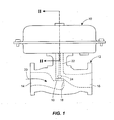
- FIG. 1 illustrates an actuator 10 constructed in accordance with the principles of the present invention and connected to a fluid process control device 12.
- the control device 12 comprises a globe valve defining an inlet 14, an outlet 16, a throat 18, and a flow-path 20.
- the flow-path 20 is disposed between the inlet 14 and the outlet 16.
- the control device 12 is adapted to be disposed within a fluid process control system including, for example, a process plant such as a refinery, or a chemical, pulp, or paper plant.
- the control device 12 controls the flow of a fluid through the system in accordance with one or more operating parameters.
- the actuator 10 comprises a stem 22 including a valve plug 24 disposed for sliding displacement within the throat 18 of the control device 12. Therefore, during operation, the actuator 12 moves the stem 22, and therefore, the plug 24, relative to a valve seat 19 disposed within the throat 18 of the control device 12. A position of the plug 24 relative to the valve seat 19 controls a quantity of fluid traveling through the flow-path 20, as may be desired for any give process application.
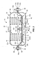
- the actuator 10 comprises a housing 26, a diaphragm assembly 28, and a plurality of springs 30.
- the housing 26 defines an internal cavity 27.
- the diaphragm assembly 28 is disposed within the housing 26 such as to divide the internal cavity 27 into an upper cavity 27a and a lower cavity 27b.
- the diaphragm assembly 28 provides a fluid-tight seal between the upper and lower cavities 27a, 27b of the housing 26.
- the springs 30 bias the diaphragm assembly 28 downward relative to the orientation of the actuator 10 depicted in FIG. 2 . This downward bias positions the plug 24 (shown in FIG.
- a pressure may be introduced into the lower cavity 27b of the housing 26 to force the diaphragm assembly 28 upward against the bias of the springs 30, thereby lifting the plug 24 away from the valve seat 19 to open the flow path 20 of the control valve 12.
- the housing 26 of the actuator 10 comprises an upper housing component 32 and a lower housing component 34.
- Each housing component 32, 34 comprises a plate portion 32a, 34a, a wall 32b, 34b, and a flange 32c, 34c.
- the plate portions 32a, 34a are generally circular. Therefore, the walls 32b, 34b and the flanges 32c, 34c extend circumferentially about the plate portions 32a, 34a.
- the radial flanges 32c, 34c define a plurality of apertures 36 for receiving fasteners 38 to secure the upper housing component 32 to the lower housing component 34, as illustrated in FIG. 2 .
- the fasteners 38 each comprise a hexagonal nut in threaded engagement with a hexagonal bolt.
- the upper housing component 32 defines a fluid port 40 and the lower housing component 34 defines a fluid port 42.
- the fluid ports 40, 42 are adapted to be coupled to respective fluid supply lines, such as pneumatic supply lines, for varying the pressure within the upper and lower cavities 27a, 27b of the housing 26.
- the lower housing component 34 defines an opening 44 for accommodating the stem 22.
- the stem 22 operatively couples the diaphragm assembly 28 to the fluid process control device 12.
- the stem 22 generally comprises an elongated rod having a body portion 22a, a threaded end portion 22b, and a shoulder 22c.
- the body portion 22a includes a diameter that is larger than a diameter of the threaded end portion 22b.
- the shoulder 22c is disposed between the body portion 22a and the threaded end portion 22b.
- the shoulder 22c defines a shoulder surface 46, which is identified in FIG. 3 .
- the shoulder surface 46 comprises a frustoconical surface that radially converges from the body portion 22a toward the threaded end portion 22b.
- the threaded end portion 22b of the stem 22 is coupled to the diaphragm assembly 28 with a nut 48.
- the nut 48 of the disclosed embodiment includes a hexagonal nut threaded onto the threaded end portion 22b of the stem 22 opposite the diaphragm assembly 28 from the shoulder portion 22c. Additionally, in the disclosed embodiment, the nut 48 is retained on the stem 22 with a retaining nut 50. The retaining nut 50 is threaded onto the threaded end portion 22b of the stem 22 and into engagement with the nut 48 to prevent the nut 48 from loosening off of the stem 22. Additionally, as will be discussed below, the diaphragm assembly 28 applies a force to the nut 48, thereby preventing the nut 48 from loosening off of the stem 22.
- the diaphragm assembly 28 comprises a pair of diaphragm plates 52, 54 and a diaphragm 56.
- the diaphragm 56 is constructed of a flexible material that may include a fabric, a polymer, a composite, and/or any other suitable material capable of providing a fluid tight seal. More specifically, the diaphragm 56 comprises an outer radial portion 56a and an inner radial portion 56b.
- the outer radial portion 56a defines a plurality of apertures 58 for receiving the fasteners 38 that secure the radial flange portions 32c, 34c of the upper and lower housing components 32, 34 together. So configured, the radial flange portions 32c, 34c compress the outer radial portion 56a of the diaphragm 56.
- the inner radial portion 56b of the diaphragm 56 includes an inner edge 60 defining a circular opening 62, as depicted in FIG. 3 .
- the inner edge 60 comprises a bead 64 that extends the circumference of the opening 62.
- the bead 64 includes a generally circular cross-section having a diameter that is larger than a thickness of the diaphragm 56. Accordingly, the inner radial portion 56b of the diaphragm 56 is disposed between the pair of diaphragm plates 52, 54.
- the diaphragm plates 52, 54 comprise outer radial portions 52a, 54a and inner radial portions 52b, 54b, as identified in FIG. 3 .
- the diaphragm plates 52, 54 are substantially identical, and therefore, common features will be identified with common reference numerals.
- the outer radial portions 52a, 54a of the diaphragm plates 52, 54 each comprise a flared edge 66 defining a rounded surface 66a.
- the outer radial portions 52a, 54a are adapted to compress the inner radial portion 56a of the diaphragm 56 to provide a fluid-tight seal.
- the diaphragm 56 may intermittently engage the curved surfaces 66a of the flared edges 66.
- These curved surface 66a advantageously provide a smooth surface for the diaphragm 56 to bear against during use without puncturing, tearing, cutting, or otherwise damaging the diaphragm 56. Accordingly, the flared edges 66 serve to ensure proper operation of the actuator 10 and maximize the operational life of the diaphragm 56.
- the inner radial portions 52b, 54b of the diaphragm plates 52, 54 each comprise a plurality of protrusions 70 and a central aperture 71, as depicted in FIG. 4 .
- FIG. 4 only depicts the upper diaphragm plate 52 and the diaphragm 56 as the lower diaphragm plate 54 is hidden below the upper diaphragm plate 52 and the diaphragm 56.
- the plurality of protrusions 70 of the disclosed embodiment includes two protrusions 70, which are generally circular and have diameters sized and configured to be received by the springs 30.
- the protrusions 70 have diameters slightly smaller than inner diameters of the springs 30 such that the protrusions retain the axial position of the springs 30 relative to the diaphragm plates 52, 54.
- the protrusions 70 are formed integral with the diaphragm plates 52, 54 such as by stamping, pressing, or some other known process.
- the inner radial portions 52b, 54b of the diaphragm plates 52, 54 further define recesses 73.
- the recesses 73 are formed in the diaphragm plates 52, 54 opposite the protrusions 70.
- the recesses 73 of the corresponding diaphragm plates 52, 54 define cavities 75 when the diaphragm assembly 28 is completely assembled.
- the central apertures 71 of the diaphragm plates 52, 54 are adapted to receive the stem 22 to enable connection of the stem 22 to the diaphragm assembly 28. While both the diaphragm plates 52, 54 define central apertures 71, the central aperture 71 in the lower diaphragm plate 54 comprises a shoulder surface 72 and a bearing surface 74.
- the bearing surface 74 is generally cylindrical and the shoulder surface 72 is generally frustoconical. More specifically, the shoulder surface 72 comprises a generally frustoconical surface adapted for sealing engagement with the shoulder surface 46 (shown in FIG. 3 ) of the stem 22. For example, in FIG.
- the shoulder surface 72 of the central aperture 71 defined by the lower diaphragm plate 54 directly engages the shoulder surface 46 of the stem 22.
- the shoulder surface 72 of the lower diaphragm plate 54 provides for a fluid-tight seal with the shoulder surface 46 of the stem 22 by providing at least a complete, continuous, and constant line of contact therewith.
- the mating frustoconical surfaces 36, 72 preferably include highly finished surfaces, thereby providing a complete, continuous, and constant surface contact therebetween.
- the bearing surfaces 74 of the central aperture 71 in the lower diaphragm plate 54 is disposed adjacent the threaded end portion 22b of the stem 22.
- the inner radial portions 52b, 54b of the diaphragm plates 52, 54 can generally resemble Belleville washers in that they have curved cross-sections, as shown in FIG. 3 .
- the upper diaphragm plate 52 comprises a generally convex cross-section
- the lower diaphragm plate 54 comprises a generally concave cross-section. Therefore, prior to assembly, each of the plates 52, 54 resemble hollow partial spheres or spherical caps.
- the inner radial portions 52b, 54b are drawn together onto the threaded end portion 22b of the stem 22, thereby substantially flattening the plates 52, 54, as depicted in FIG. 2 . In one embodiment, this flattening of the plates 52, 54 may also at least partly increase the diameter of the plates 52, 54.
- the lower diaphragm plate 54 is disposed in a concave orientation on the threaded end portion 22b of the stem 22. So configured, the shoulder surface 72 of the central aperture 71 of the lower diaphragm plate 54 directly engages the shoulder surface 46 of the stem 22, as depicted in FIG. 2 .
- the lower diaphragm plate 54 continues to resemble a spherical cap having a generally concave cross-section.
- the diaphragm 56 is positioned on the lower diaphragm plate 54 such that the inner radial portion 56b of the diaphragm 56 rests on the outer radial portion 54a of the lower diaphragm plate 54. When properly positioned, the bead 64 on the inner edge 60 of the diaphragm 56 lies within the recesses 73 formed in the lower diaphragm plate 54.
- the upper diaphragm plate 52 With the diaphragm 56 properly positioned on the lower diaphragm plate 54, the upper diaphragm plate 52 is disposed in a convex orientation on the stem 22 such that the central aperture 71 thereof is received on the threaded end portion 22b. At this point, the inner radial portions 52b, 54b of the diaphragm plates 52, 54 define a cavity (not shown) therebetween. Finally, the nut 48 is tightened onto the threaded end portion 22b of the stem 22. Tightening the nut 48 causes the nut 48 to engage the upper diaphragm plate 52 and axially compress the diaphragm plates 52, 54 together.
- the nut 48 flattens and compresses the inner radial portions 52b, 54b of the diaphragm plates 52, 54 into engagement with each other between the nut 48 and the shoulder 22c of the stem 22, as depicted in FIG. 2 .
- the retaining nut 50 may be threaded onto the stem 22 and into engagement with the nut 48.
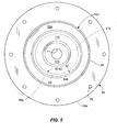
- FIG. 4 depicts a plan view of the assembly taken from line IV-IV in FIG. 3 , with the bolt 48 and retainer 50 removed for clarity, and showing the diaphragm 56 disposed between the upper and lower diaphragm plates 52, 54.
- the bead 64 formed on the inner edge 60 of the diaphragm 56 includes portions 64a disposed within the cavities 75 formed between the recesses 73 in the diaphragm plates 52, 54.
- these portions 64a of the bead 64 at least partly secure the diaphragm 56 against pulling out from between the diaphragm plates 52, 54.
- the bead 64 also includes portions 64b that are not disposed within the cavities 75, but rather disposed circumferentially between the cavities 75. These portions 64b are compressed between outer radial portions 52a, 54a of the diaphragm plates 52, 54 to substantially the same thickness as the remainder of the diaphragm 56. Thus, these portion 64b of the bead 64 do not interrupt or interfere with the seal formed between the plates 52, 54 and the diaphragm 56.
- the inner radial portions 52b, 54b of the diaphragm plates 52, 54 urge themselves in opposite directions away from each other. So configured, the shoulder surface 72 of the central aperture 71 of the lower diaphragm plate 54 is forced downward relative to the orientation of the actuator 10 depicted in FIG. 2 and into line-contact, fluid-tight, sealing engagement with the shoulder surface 46 of the stem 22. Furthermore, the inner radial portion 52b of the upper diaphragm plate 52 is forced upward relative to the orientation of the actuator 10 depicted in FIG. 3 and into engagement with the nut 48.
- the force applied to the nut 48 by the upper diaphragm plate 52 generates sufficient friction between the threads of the nut 48 and the threads on the threaded end portion 22b to prevent the nut 48 from involuntarily loosening off of the threaded end portion 22b of the stem 22 during prolonged operation of the actuator 10.
- the shoulder portion 22c of the stem 22 and the nut 48 retain the diaphragm plates 52, 54 in the compressed and flattened configuration depicted in FIG. 2 , which coincidentally applies a tensile load to a portion of the threaded end portion 22b of the stem 22 that is located between the upper and lower diaphragm plates 52, 54.
- the diaphragm assembly 28 described herein advantageously comprises diaphragm plates 52, 54 designed and configured to compressively engage and seal with a diaphragm 56 while simultaneously and directly sealing against a stem 22 to provide a fluid-tight seal between the upper and lower cavities 27a, 27b of the housing 26, as well as applying a force to retain the nut 48 on the stem 22.
- the actuator 10 of the present invention has, thus far, been disclosed as comprising a nut 48 connecting the stem 22 to the diaphragm assembly 28, an alternative embodiment may not require a nut.
- the central aperture 71 defined in the upper diaphragm plate 52 may include internal threads. The internal threads of the central aperture 71 may be sized and configured for threaded engagement with the threaded end portion 22b of the stem 22. So configured, the threaded end portion 22b of the stem 22 would be disposed in direct threaded engagement with the internal threads of the upper diaphragm plate 52.
- Tightening the threaded end portion 22b of the stem 22 to the upper diaphragm plate 52 would draw the inner radial portions 52b, 54b of the diaphragm plates together, as depicted in FIG. 2 , for example.
- the retaining nut 50 may be utilized to assist in retaining the stem 22 and upper diaphragm plate 52 together, however, the force inherently generated by deforming and compressing the diaphragm plates 52, 54 would generate sufficient friction between the threaded end portion 22b of the stem 22 and the central aperture 71 to prevent the stem 22 from loosening from the upper diaphragm plate 52.
- the diaphragm 56 has been disclosed herein as comprising a bead 64 having a generally circular cross-section formed in the inner edge 60, one alternative example not forming part of the claimed invention may not comprise a bead 64. Rather, the compressive force generated by the outer radial portions 52a, 54a of the diaphragm plates 52, 54 would sufficiently retain the diaphragm 56 between the diaphragm plates 52, 54.
- the diaphragm 56 may comprise multiple bead portions formed on the inner edge 60. For example, in the embodiment depicted in FIG.
- the diaphragm 56 may only include the bead portions 64a disposed within the cavities 75, but not the bead portions 64b. Such an example would require the technician assembling the actuator 10 to ensure proper location of the bead portions 64a within the cavities 75 during assembly.
- the bead 64 can be constructed to have a cross-section other than circular.
- alternative embodiments can include a bead 64 with a square, rectangular, triangular, diamond- shaped, or other shaped cross-section.
- the bead 64 can be constructed to include an inner reinforcing ring 285 such as that depicted in FIG. 6 , for example.
- the inner reinforcing ring 285 depicted in FIG. 6 is disposed within the diaphragm 56 and defines an overmolded bead 264.
- the overmolded bead 264 is formed of an outer material that is consistent with the material forming the remainder of the diaphragm 56.
- the inner reinforcing ring 285 can be constructed of a metal, a thermoplastic, a high durometer polymer, a polymer, or any other material capable of serving the principles of the invention.
- the reinforcing ring 285 can prevent extrusion of the bead 264 in certain applications. While the inner reinforcing ring 285 is depicted in FIG. 6 as having a circular cross-section, alternative examples of the reinforcing ring 285 not forming part of the claimed invention can have generally any shape cross-section.
- the lower diaphragm plate 54 has been disclosed herein as comprising a central aperture 71 including a generally frustoconical shoulder surface 72 adapted for direct sealing engagement with a corresponding frustoconical shoulder surface 46 of the stem 22, alternative embodiments of the diaphragm assembly 28 may comprise alternative configurations.
- one alternative embodiment may include a lower diaphragm plate 54 having a central aperture 71 with a stepped surface adapted for direct sealing engagement with a stepped surface formed on the stem 22.
- the central aperture 71 and the stem 22 may simply include flat surfaces adapted for direct sealing engagement.
- one of the stem 22 and the central aperture 71 may include a collar and the other may include an annular recess adapted to receive the collar in a snap-fit sealing engagement.
- either or both of the shoulder surfaces 46, 72 can include a bull-nosed surface.
- Fig. 7 depicts one alternative embodiment where the shoulder surface 46 on the stem 22 includes a bull-nosed surface and the surface 72 of the central aperture 71 in the lower diaphragm plate 54 includes a frustoconical surface. So configured, the bull-nosed surface 46 helps maintain the line of contact providing the fluid-tight seal between the stem 22 and the lower diaphragm plate 54 even if the stem 22 and the plate 54 become misaligned, for example.
- the shoulder surface 46 can be frustoconical, and the surface 72 on the lower diaphragm plate 54 can be bull-nosed; or alternatively, both surfaces 46, 72 can be bull-nosed.
- the present invention is not limited to the geometrical configurations of the surfaces 72, 46 specifically disclosed herein, but rather is intended to include all geometries that a person having ordinary skill in the art would deem to be within the scope and terms of the claims.
- diaphragm plates 52, 54 have been disclosed herein with reference to FIG. 4 as including a pair of protrusions 70 serving as spring seats for a pair of springs 30, alternative embodiments may include any number of springs 30 and protrusions 70 acting as spring seats.
- FIG. 5 depicts an alternative example not forming part of the claimed invention of the diaphragm plates 152, 154 including circumferential protrusions 170. It should be appreciated that FIG. 5 only depicts the upper diaphragm plate 152 and the diaphragm 56 as the lower diaphragm plate 154 is hidden below the upper diaphragm plate 152 and the diaphragm 56.
- the diaphragm plates 152, 154 of the example disclosed in FIG. 5 also include circumferential recesses 173 that define a circumferential cavity 175 when assembled onto the stem 22 of the actuator 10.
- the cross-section of the cavity 175 of the example depicted in FIG. 5 therefore, would be illustrated identical to cross-section of the multiple cavities 75 illustrated in FIG. 2 .
- a distinction between the configuration depicted in FIG. 4 and the configuration depicted in FIG. 5 is that the circumferential cavity 175 receives or accommodates the entire bead 64 on the inner edge 60 of the diaphragm 56.
- the circumferential protrusions 170 of the diaphragm plates 152, 154 are adapted to act as a spring seat to accommodate one or more springs disposed concentrically with the diaphragm plates 152, 154.
- a first spring having a diameter that is slightly smaller than the inner diameter of the protrusion 170 may be seated on the upper diaphragm plate 152 within the protrusion 170. The protrusion 170 would therefore prevent the spring from displacing radially relative to the upper diaphragm plate 152.
- Another example not forming part of the claimed invention may alternatively or supplementally include another spring having a diameter that is slightly larger than the outer diameter of the protrusion 170. So configured, this spring may be seated on the upper diaphragm plate 152 such that it receives the protrusion 170 to thereby limit its radial displacement. Therefore, it should be appreciated that other variations of the diaphragm plates and spring configurations may be within the scope of the present invention.
- the protrusions 70 forming the spring seats have been disclosed herein as being formed integral with the diaphragm plates 52, 54, alternative embodiments may include spring seats that are not integrally formed with the diaphragm plates 52, 54.
- the diaphragm assembly 28 may include spring seats welded onto, bolted onto, or otherwise attached to the diaphragm plates 52, 54.
- the diaphragm plates 52, 54 may not include spring seats at all, but rather the upper and/or lower housing components 32, 34 may include spring seats.
- the disclosed actuator 10 provides a diaphragm assembly 28 which requires a minimum number of parts and assembly steps.
- the diaphragm assembly 28 advantageously provides spring loaded diaphragm plates 52, 54 that, when assembled, directly and forcibly engage the stem 22, as well as the diaphragm 56, to provide a fluid-tight seal between the upper and lower cavities 27a, 27b of the housing 26.
- the diaphragm assembly 28 disclosed herein does not require the incorporation of o-rings, rubber gaskets, or any other type of seal, which tend to require replacement after prolonged use. Accordingly, the diaphragm assembly 28 provides for an effective and reliable actuator 1.0.
- the forces generated by the compressed diaphragm plates 52, 54 enable the diaphragm assembly 28 disclosed herein to advantageously require only a single nut 48 for attaching the diaphragm plates 52, 54 to the stem 22.
- the upper diaphragm plate 52 applies an axial load to the nut 48 which generates sufficient friction between the threads of the nut 48 and the stem 22.
- the annular design of the diaphragm 56 disclosed herein advantageously reduces the cost of the actuator 10.
- the design of the diaphragm assembly 28 enables the diaphragm 56 to be constructed with the inner opening 62, which greatly reduces the amount of required diaphragm material.
- the identical nature of the diaphragm plates 52, 54 provides for an actuator 10 that is easily reversible between the biased-closed configuration, which is disclosed herein, and a biased open-configuration.
- a technician or other engineer must only open the housing 26 of the actuator 10 and reposition the springs 30 beneath the diaphragm assembly 28 and in engagement with the protrusions 70 formed in the lower diaphragm plate 54.
Landscapes
- Engineering & Computer Science (AREA)
- General Engineering & Computer Science (AREA)
- Mechanical Engineering (AREA)
- Actuator (AREA)
- Diaphragms And Bellows (AREA)
- Fluid-Driven Valves (AREA)
- Reciprocating Pumps (AREA)
- Packages (AREA)
Claims (6)
- Stellglied (10) für eine Fluidprozesssteuerungsvorrichtung (12), Folgendes aufweisend:ein Gehäuse (26) mit einem ersten Gehäusebestandteil (32) und einem zweiten Gehäusebestandteil (34);eine Membran (56) mit einem äußeren radialen Abschnitt (56a) und einem inneren radialen Abschnitt (56b), wobei der äußere radiale Abschnitt (56a) der Membran (56) zwischen dem ersten und zweiten Gehäusebestandteil (32, 34) gehalten ist, wobei der innere radiale Abschnitt (56b) eine innere Öffnung (62) und eine Rippe (64) aufweist, die sich um einen Umfang der Öffnung (62) erstreckt;einen Schaft (22), der in Wirkverbindung mit der Membran (56) steht, um die Fluidprozesssteuerungsvorrichtung (12) zu steuern, wobei der Schaft (22) eine Schulter (22c) und einen mit Gewinde versehenen Endabschnitt (22b) aufweist;undeine Tellerbaugruppe (28), die den Schaft (22) und die Membran (56) verbindet, wobei die Tellerbaugruppe (28) einen konkaven Teller (54) und einen konvexen Teller (52) umfasst, welche die Membran (56) zwischen sich zusammendrücken, wobei eine mit Gewinde versehene Einrichtung, die auf den mit Gewinde versehenen Endabschnitt (22b) aufgeschraubt ist, die Tellerbaugruppe (28) gegen die Schulter (22c) zusammendrückt, und den konkaven Teller (54) und den konvexen Teller (52) zusammendrückt und abflacht, wobei die Tellerbaugruppe (28) eine Druckbelastung an den inneren radialen Abschnitt (56b) der Membran (56) und die Rippe (64) anlegt und eine Kontaktlinie mit dem Schaft (22) bereitstellt, um eine fluiddichte Abdichtung zwischen der Tellerbaugruppe (28) und dem Schaft (22) bereitzustellen,wobeiTeile (64a) der Rippe (64) in Hohlräumen (75) angeordnet sind, die zwischen Vertiefungen (73) in dem konkaven und konvexen Teller (52, 54) gebildet sind,um die Membran (56) teilweise gegen ein Herausziehen aus zwischen dem konkaven und konvexen Teller (52, 54) zu sichern, und Teile (64b) der Rippe (64) nicht in den Hohlräumen (75) sondern umfänglich zwischen den Hohlräumen (75) angeordnet und zwischen dem konkaven und konvexen Teller (52, 54) auf im Wesentlichen dieselbe Dicke wie der Rest der Membran (56) zusammengedrückt sind;wobei die zusammengedrückte und abgeflachte Auslegung des konkaven undkonvexen Tellers (52, 54) eine Zugbelastung an einen Teil des mit Gewinde versehenen Endabschnitts (22b) des Schafts (22) an einer Stelle zwischen dem konkaven und konvexen Teller (52, 54) anlegt, um einen fluiddichten Abdichtungseingriff zwischen dem konkaven Teller (54) und einer Schulteroberfläche (46) der Schulter (22c) des Schafts (22) bereitzustellen.
- Stellglied (10) nach Anspruch 1, wobei die Schulteroberfläche (46) eine erste kegelstumpfförmige Fläche aufweist, und der konkave Teller (54) eine zentrale Öffnung (71) mit einer zweiten kegelstumpfförmigen Fläche (72) definiert, welche die erste kegelstumpfförmige Fläche der Schulter (22c) in Eingriff hält.
- Stellglied (10) nach Anspruch 1, wobei der konkave Teller (54) eine zentrale Öffnung (71) definiert, und die zentrale Öffnung (71) und/oder die Schulteroberfläche (46) des Schafts (22) eine abgerundete Fläche aufweist.
- Stellglied (10) nach Anspruch 1, wobei die mit Gewinde versehene Einrichtung eine Schraubenmutter (48) umfasst, die auf den mit Gewinde versehenen Endabschnitt (22b) des Schafts (22) aufgeschraubt ist, wodurch die inneren radialen Abschnitte (52b, 54b) des konkaven und konvexen Tellers (52, 54) zwischen der Schulter (22c) und der Schraubenmutter (48) zusammengedrückt werden.
- Stellglied (10) nach Anspruch 1, wobei die mit Gewinde versehene Einrichtung eine mit Gewinde versehene Öffnung umfasst, die im konvexen Teller (52) in Gewindeeingriff mit dem mit Gewinde versehenen Endabschnitt (22b) des Schafts (22) definiert ist.
- Stellglied (10) nach Anspruch 1, wobei die Rippe (64) einen Querschnitt aufweist, der kreisförmig, dreieckig, recheckig oder rautenförmig ist.
Priority Applications (2)
| Application Number | Priority Date | Filing Date | Title |
|---|---|---|---|
| EP14163983.1A EP2767745B1 (de) | 2007-12-07 | 2008-11-25 | Mit Ring abgedichtetes Diaphragma |
| EP16187647.9A EP3159586B1 (de) | 2007-12-07 | 2008-11-25 | Mit ring abgedichtetes diaphragma |
Applications Claiming Priority (2)
| Application Number | Priority Date | Filing Date | Title |
|---|---|---|---|
| US11/952,753 US7832327B2 (en) | 2007-12-07 | 2007-12-07 | Ring sealed diaphragm |
| PCT/US2008/084722 WO2009073486A1 (en) | 2007-12-07 | 2008-11-25 | Ring sealed diaphragm |
Related Child Applications (3)
| Application Number | Title | Priority Date | Filing Date |
|---|---|---|---|
| EP14163983.1A Division-Into EP2767745B1 (de) | 2007-12-07 | 2008-11-25 | Mit Ring abgedichtetes Diaphragma |
| EP14163983.1A Division EP2767745B1 (de) | 2007-12-07 | 2008-11-25 | Mit Ring abgedichtetes Diaphragma |
| EP16187647.9A Division EP3159586B1 (de) | 2007-12-07 | 2008-11-25 | Mit ring abgedichtetes diaphragma |
Publications (2)
| Publication Number | Publication Date |
|---|---|
| EP2225486A1 EP2225486A1 (de) | 2010-09-08 |
| EP2225486B1 true EP2225486B1 (de) | 2014-07-09 |
Family
ID=40386352
Family Applications (3)
| Application Number | Title | Priority Date | Filing Date |
|---|---|---|---|
| EP16187647.9A Active EP3159586B1 (de) | 2007-12-07 | 2008-11-25 | Mit ring abgedichtetes diaphragma |
| EP14163983.1A Active EP2767745B1 (de) | 2007-12-07 | 2008-11-25 | Mit Ring abgedichtetes Diaphragma |
| EP08857103.9A Active EP2225486B1 (de) | 2007-12-07 | 2008-11-25 | Membran mit ringabdichtung |
Family Applications Before (2)
| Application Number | Title | Priority Date | Filing Date |
|---|---|---|---|
| EP16187647.9A Active EP3159586B1 (de) | 2007-12-07 | 2008-11-25 | Mit ring abgedichtetes diaphragma |
| EP14163983.1A Active EP2767745B1 (de) | 2007-12-07 | 2008-11-25 | Mit Ring abgedichtetes Diaphragma |
Country Status (11)
| Country | Link |
|---|---|
| US (1) | US7832327B2 (de) |
| EP (3) | EP3159586B1 (de) |
| JP (2) | JP5503550B2 (de) |
| CN (1) | CN101855482B (de) |
| AU (1) | AU2008331474B2 (de) |
| BR (1) | BRPI0819637A2 (de) |
| CA (1) | CA2706687C (de) |
| MX (1) | MX2010006261A (de) |
| NO (1) | NO339818B1 (de) |
| RU (1) | RU2496043C2 (de) |
| WO (1) | WO2009073486A1 (de) |
Families Citing this family (8)
| Publication number | Priority date | Publication date | Assignee | Title |
|---|---|---|---|---|
| US9476516B2 (en) | 2011-07-15 | 2016-10-25 | Mecanique Analytique Inc. | Actuator |
| JP6039664B2 (ja) | 2011-07-15 | 2016-12-07 | メカニック・アナリティック・インコーポレーテッド | アクチュエータ |
| CN103174553A (zh) * | 2013-03-29 | 2013-06-26 | 无锡隆盛科技股份有限公司 | 增强阀杆运动垂直度的真空egr阀结构 |
| US10215297B2 (en) * | 2016-01-20 | 2019-02-26 | Fisher Controls International Llc | Control regulator diaphragm assembly with integrated pressure relief |
| KR101830166B1 (ko) * | 2017-04-11 | 2018-02-21 | 한국본산 주식회사 | 밸브용 다이아프램식 액추에이터 |
| DE202017104079U1 (de) * | 2017-07-07 | 2017-08-21 | Samson Ag | Stellantrieb für Prozessventile |
| KR101876302B1 (ko) * | 2017-11-15 | 2018-07-09 | 주식회사 프로발 | 내압성능이 개선된 다이아프램 방식 밸브 모듈 |
| CN108413028A (zh) * | 2018-05-15 | 2018-08-17 | 西安法士特汽车传动有限公司 | 一种取力器气缸及挂挡装置 |
Family Cites Families (33)
| Publication number | Priority date | Publication date | Assignee | Title |
|---|---|---|---|---|
| DE644363C (de) | 1934-06-06 | 1937-04-29 | Hermann Wolf | Fluessigkeitsstossdaempfer fuer Fahrzeuge |
| US2809521A (en) * | 1954-06-04 | 1957-10-15 | Waddell Inc | Diaphragm for gas meters |
| US2931179A (en) * | 1957-12-03 | 1960-04-05 | Bishop And Babcock Mfg Company | Automobile power brakes for manual or pedal operation |
| US2934307A (en) * | 1957-12-11 | 1960-04-26 | Walter P Henderson | Valves |
| US3081847A (en) * | 1961-12-26 | 1963-03-19 | Holley Carburetor Co | Dashpot |
| US3304880A (en) * | 1964-11-06 | 1967-02-21 | Gen Motors Corp | Pump and diaphragm plunger sub-assembly |
| US3486491A (en) * | 1968-06-20 | 1969-12-30 | Acf Ind Inc | Automotive deceleration device |
| US3542289A (en) * | 1968-09-24 | 1970-11-24 | Ford Motor Co | Snap action thermally responsive valve |
| DE2241551A1 (de) | 1972-08-24 | 1974-04-25 | Fritz Mueller | Durchgangsventil |
| US3933950A (en) * | 1974-05-02 | 1976-01-20 | General Motors Corporation | Air valve carburetor |
| AT340031B (de) * | 1976-03-03 | 1977-11-25 | Hoerbiger Ventilwerke Ag | Steueranordnung fur die oleinspritzung in einen schraubenverdichter |
| US4196744A (en) * | 1976-09-21 | 1980-04-08 | Eaton Corporation | Exhaust gas recirculation control |
| US4125293A (en) * | 1977-10-05 | 1978-11-14 | Westinghouse Air Brake Company | Emergency portion for brake control valve |
| JPS5491615A (en) * | 1977-12-29 | 1979-07-20 | Toyota Motor Corp | Secondary air supply apparatus for engine exhaust system |
| US4241757A (en) * | 1979-03-26 | 1980-12-30 | Dan Bron | Flow regulator |
| JPS57200779A (en) | 1981-06-02 | 1982-12-09 | Honda Motor Co Ltd | Pressure sensitive valve |
| EP0298149A1 (de) * | 1982-10-19 | 1989-01-11 | Stordy Combustion Engineering Limited | Durchflussregeleinrichtung |
| JPS61193261U (de) * | 1985-05-25 | 1986-12-01 | ||
| JPS6224076A (ja) * | 1985-07-25 | 1987-02-02 | Yamatake Honeywell Co Ltd | ダイヤフラムおよびその成形方法 |
| KR870006308A (ko) * | 1985-12-10 | 1987-07-10 | 미타 가쓰시게 | 자동차용 아이들회전 제어장치 |
| JPS643155U (de) * | 1987-06-25 | 1989-01-10 | ||
| JPH01105733U (de) * | 1988-01-08 | 1989-07-17 | ||
| JPH01158804U (de) * | 1988-04-22 | 1989-11-02 | ||
| DE4139895C2 (de) * | 1991-12-04 | 1995-03-30 | Danfoss As | Bausatz für ein Differenzdruckregelventil |
| CH689332A5 (de) * | 1993-09-20 | 1999-02-26 | Fischer Georg Rohrleitung | Absperrventil mit einem Stellantrieb. |
| WO1995023937A1 (en) * | 1994-03-04 | 1995-09-08 | Safoco, Inc. | Valve actuator apparatus and method |
| DE19514978A1 (de) | 1995-04-24 | 1996-10-31 | Richter Chemie Tech Itt Gmbh | Membranventil |
| US5586744A (en) * | 1995-05-11 | 1996-12-24 | Caterpillar Inc. | Boost device bypass valve |
| US6347620B1 (en) * | 1998-04-23 | 2002-02-19 | Mitsubishi Denki Kabushik Kaisha | Control valve unit |
| DE19830084C1 (de) | 1998-07-06 | 1999-10-21 | Richter Albert Ari Armaturen | Stellventil |
| JP3695501B2 (ja) * | 1998-07-31 | 2005-09-14 | Nok株式会社 | ダイアフラムアクチュエータ |
| US6827001B2 (en) * | 2003-02-06 | 2004-12-07 | Fisher Controls International Llc | Pressure actuator diaphragm casing with air passages |
| DE102006004183B4 (de) * | 2006-01-27 | 2007-10-11 | Danfoss A/S | Ventilanordnung zum Anschließen eines Wärmetauschers einer Warmwasserentnahmevorrichtung an ein Fernwärmenetz |
-
2007
- 2007-12-07 US US11/952,753 patent/US7832327B2/en active Active
-
2008
- 2008-11-25 EP EP16187647.9A patent/EP3159586B1/de active Active
- 2008-11-25 RU RU2010125714/06A patent/RU2496043C2/ru active
- 2008-11-25 CN CN2008801156522A patent/CN101855482B/zh active Active
- 2008-11-25 CA CA2706687A patent/CA2706687C/en active Active
- 2008-11-25 WO PCT/US2008/084722 patent/WO2009073486A1/en not_active Ceased
- 2008-11-25 EP EP14163983.1A patent/EP2767745B1/de active Active
- 2008-11-25 BR BRPI0819637 patent/BRPI0819637A2/pt not_active Application Discontinuation
- 2008-11-25 AU AU2008331474A patent/AU2008331474B2/en not_active Ceased
- 2008-11-25 EP EP08857103.9A patent/EP2225486B1/de active Active
- 2008-11-25 MX MX2010006261A patent/MX2010006261A/es active IP Right Grant
- 2008-11-25 JP JP2010536992A patent/JP5503550B2/ja not_active Expired - Fee Related
-
2010
- 2010-05-14 NO NO20100704A patent/NO339818B1/no not_active IP Right Cessation
-
2014
- 2014-03-14 JP JP2014051423A patent/JP5990551B2/ja not_active Expired - Fee Related
Also Published As
| Publication number | Publication date |
|---|---|
| AU2008331474A1 (en) | 2009-06-11 |
| CA2706687A1 (en) | 2009-06-11 |
| WO2009073486A1 (en) | 2009-06-11 |
| NO20100704L (no) | 2010-05-14 |
| EP2225486A1 (de) | 2010-09-08 |
| JP5990551B2 (ja) | 2016-09-14 |
| JP5503550B2 (ja) | 2014-05-28 |
| BRPI0819637A2 (pt) | 2015-05-05 |
| US7832327B2 (en) | 2010-11-16 |
| EP2767745B1 (de) | 2017-04-05 |
| AU2008331474B2 (en) | 2015-03-12 |
| JP2011506863A (ja) | 2011-03-03 |
| CN101855482B (zh) | 2012-10-31 |
| JP2014132194A (ja) | 2014-07-17 |
| EP2767745A1 (de) | 2014-08-20 |
| EP3159586A1 (de) | 2017-04-26 |
| NO339818B1 (no) | 2017-02-06 |
| CN101855482A (zh) | 2010-10-06 |
| CA2706687C (en) | 2015-01-06 |
| US20090145294A1 (en) | 2009-06-11 |
| RU2496043C2 (ru) | 2013-10-20 |
| MX2010006261A (es) | 2010-06-23 |
| RU2010125714A (ru) | 2012-01-20 |
| EP3159586B1 (de) | 2018-09-05 |
Similar Documents
| Publication | Publication Date | Title |
|---|---|---|
| EP2225486B1 (de) | Membran mit ringabdichtung | |
| EP0581287B1 (de) | Regelventil mit Membranabstützung | |
| US8960216B2 (en) | Diaphragm control valve having a universal diaphragm mounting location | |
| WO2008079692A1 (en) | Apparatus to seal a shaft to a diaphragm actuators | |
| US20030042459A1 (en) | Unitary diaphragm and seat assembly | |
| US8152132B2 (en) | Pneumatic actuator having diaphragm retention ring | |
| EP3405710B1 (de) | Membrananordnung eines steuerreglers mit integrierter druckentlastung | |
| GB2433102A (en) | Valve | |
| CA3010230C (en) | Control regulator diaphragm assembly with integrated pressure relief | |
| CA3010204C (en) | Organic semiconducting material and use thereof in organic devices | |
| US5253673A (en) | Distribution valved manifold system |
Legal Events
| Date | Code | Title | Description |
|---|---|---|---|
| PUAI | Public reference made under article 153(3) epc to a published international application that has entered the european phase |
Free format text: ORIGINAL CODE: 0009012 |
|
| 17P | Request for examination filed |
Effective date: 20100625 |
|
| AK | Designated contracting states |
Kind code of ref document: A1 Designated state(s): AT BE BG CH CY CZ DE DK EE ES FI FR GB GR HR HU IE IS IT LI LT LU LV MC MT NL NO PL PT RO SE SI SK TR |
|
| AX | Request for extension of the european patent |
Extension state: AL BA MK RS |
|
| RIN1 | Information on inventor provided before grant (corrected) |
Inventor name: GETHMANN, DOUGLAS, PAUL Inventor name: SCHADE, ROSS, A. Inventor name: ARNOLD, DAVID, A. |
|
| DAX | Request for extension of the european patent (deleted) | ||
| 17Q | First examination report despatched |
Effective date: 20111213 |
|
| GRAP | Despatch of communication of intention to grant a patent |
Free format text: ORIGINAL CODE: EPIDOSNIGR1 |
|
| INTG | Intention to grant announced |
Effective date: 20131030 |
|
| GRAP | Despatch of communication of intention to grant a patent |
Free format text: ORIGINAL CODE: EPIDOSNIGR1 |
|
| INTG | Intention to grant announced |
Effective date: 20140213 |
|
| GRAS | Grant fee paid |
Free format text: ORIGINAL CODE: EPIDOSNIGR3 |
|
| GRAA | (expected) grant |
Free format text: ORIGINAL CODE: 0009210 |
|
| AK | Designated contracting states |
Kind code of ref document: B1 Designated state(s): AT BE BG CH CY CZ DE DK EE ES FI FR GB GR HR HU IE IS IT LI LT LU LV MC MT NL NO PL PT RO SE SI SK TR |
|
| REG | Reference to a national code |
Ref country code: GB Ref legal event code: FG4D |
|
| REG | Reference to a national code |
Ref country code: CH Ref legal event code: EP Ref country code: AT Ref legal event code: REF Ref document number: 676703 Country of ref document: AT Kind code of ref document: T Effective date: 20140715 |
|
| REG | Reference to a national code |
Ref country code: IE Ref legal event code: FG4D |
|
| REG | Reference to a national code |
Ref country code: DE Ref legal event code: R096 Ref document number: 602008033244 Country of ref document: DE Effective date: 20140821 |
|
| REG | Reference to a national code |
Ref country code: SE Ref legal event code: TRGR |
|
| REG | Reference to a national code |
Ref country code: AT Ref legal event code: MK05 Ref document number: 676703 Country of ref document: AT Kind code of ref document: T Effective date: 20140709 |
|
| REG | Reference to a national code |
Ref country code: NL Ref legal event code: VDEP Effective date: 20140709 |
|
| REG | Reference to a national code |
Ref country code: LT Ref legal event code: MG4D |
|
| PG25 | Lapsed in a contracting state [announced via postgrant information from national office to epo] |
Ref country code: LT Free format text: LAPSE BECAUSE OF FAILURE TO SUBMIT A TRANSLATION OF THE DESCRIPTION OR TO PAY THE FEE WITHIN THE PRESCRIBED TIME-LIMIT Effective date: 20140709 Ref country code: PT Free format text: LAPSE BECAUSE OF FAILURE TO SUBMIT A TRANSLATION OF THE DESCRIPTION OR TO PAY THE FEE WITHIN THE PRESCRIBED TIME-LIMIT Effective date: 20141110 Ref country code: BG Free format text: LAPSE BECAUSE OF FAILURE TO SUBMIT A TRANSLATION OF THE DESCRIPTION OR TO PAY THE FEE WITHIN THE PRESCRIBED TIME-LIMIT Effective date: 20141009 Ref country code: GR Free format text: LAPSE BECAUSE OF FAILURE TO SUBMIT A TRANSLATION OF THE DESCRIPTION OR TO PAY THE FEE WITHIN THE PRESCRIBED TIME-LIMIT Effective date: 20141010 Ref country code: NO Free format text: LAPSE BECAUSE OF FAILURE TO SUBMIT A TRANSLATION OF THE DESCRIPTION OR TO PAY THE FEE WITHIN THE PRESCRIBED TIME-LIMIT Effective date: 20141009 Ref country code: ES Free format text: LAPSE BECAUSE OF FAILURE TO SUBMIT A TRANSLATION OF THE DESCRIPTION OR TO PAY THE FEE WITHIN THE PRESCRIBED TIME-LIMIT Effective date: 20140709 |
|
| PG25 | Lapsed in a contracting state [announced via postgrant information from national office to epo] |
Ref country code: AT Free format text: LAPSE BECAUSE OF FAILURE TO SUBMIT A TRANSLATION OF THE DESCRIPTION OR TO PAY THE FEE WITHIN THE PRESCRIBED TIME-LIMIT Effective date: 20140709 Ref country code: HR Free format text: LAPSE BECAUSE OF FAILURE TO SUBMIT A TRANSLATION OF THE DESCRIPTION OR TO PAY THE FEE WITHIN THE PRESCRIBED TIME-LIMIT Effective date: 20140709 Ref country code: LV Free format text: LAPSE BECAUSE OF FAILURE TO SUBMIT A TRANSLATION OF THE DESCRIPTION OR TO PAY THE FEE WITHIN THE PRESCRIBED TIME-LIMIT Effective date: 20140709 Ref country code: CY Free format text: LAPSE BECAUSE OF FAILURE TO SUBMIT A TRANSLATION OF THE DESCRIPTION OR TO PAY THE FEE WITHIN THE PRESCRIBED TIME-LIMIT Effective date: 20140709 Ref country code: NL Free format text: LAPSE BECAUSE OF FAILURE TO SUBMIT A TRANSLATION OF THE DESCRIPTION OR TO PAY THE FEE WITHIN THE PRESCRIBED TIME-LIMIT Effective date: 20140709 Ref country code: IS Free format text: LAPSE BECAUSE OF FAILURE TO SUBMIT A TRANSLATION OF THE DESCRIPTION OR TO PAY THE FEE WITHIN THE PRESCRIBED TIME-LIMIT Effective date: 20141109 Ref country code: PL Free format text: LAPSE BECAUSE OF FAILURE TO SUBMIT A TRANSLATION OF THE DESCRIPTION OR TO PAY THE FEE WITHIN THE PRESCRIBED TIME-LIMIT Effective date: 20140709 |
|
| REG | Reference to a national code |
Ref country code: DE Ref legal event code: R097 Ref document number: 602008033244 Country of ref document: DE |
|
| PG25 | Lapsed in a contracting state [announced via postgrant information from national office to epo] |
Ref country code: CZ Free format text: LAPSE BECAUSE OF FAILURE TO SUBMIT A TRANSLATION OF THE DESCRIPTION OR TO PAY THE FEE WITHIN THE PRESCRIBED TIME-LIMIT Effective date: 20140709 Ref country code: IT Free format text: LAPSE BECAUSE OF FAILURE TO SUBMIT A TRANSLATION OF THE DESCRIPTION OR TO PAY THE FEE WITHIN THE PRESCRIBED TIME-LIMIT Effective date: 20140709 Ref country code: RO Free format text: LAPSE BECAUSE OF FAILURE TO SUBMIT A TRANSLATION OF THE DESCRIPTION OR TO PAY THE FEE WITHIN THE PRESCRIBED TIME-LIMIT Effective date: 20140709 Ref country code: EE Free format text: LAPSE BECAUSE OF FAILURE TO SUBMIT A TRANSLATION OF THE DESCRIPTION OR TO PAY THE FEE WITHIN THE PRESCRIBED TIME-LIMIT Effective date: 20140709 Ref country code: SK Free format text: LAPSE BECAUSE OF FAILURE TO SUBMIT A TRANSLATION OF THE DESCRIPTION OR TO PAY THE FEE WITHIN THE PRESCRIBED TIME-LIMIT Effective date: 20140709 Ref country code: DK Free format text: LAPSE BECAUSE OF FAILURE TO SUBMIT A TRANSLATION OF THE DESCRIPTION OR TO PAY THE FEE WITHIN THE PRESCRIBED TIME-LIMIT Effective date: 20140709 |
|
| PLBE | No opposition filed within time limit |
Free format text: ORIGINAL CODE: 0009261 |
|
| STAA | Information on the status of an ep patent application or granted ep patent |
Free format text: STATUS: NO OPPOSITION FILED WITHIN TIME LIMIT |
|
| 26N | No opposition filed |
Effective date: 20150410 |
|
| PG25 | Lapsed in a contracting state [announced via postgrant information from national office to epo] |
Ref country code: MC Free format text: LAPSE BECAUSE OF FAILURE TO SUBMIT A TRANSLATION OF THE DESCRIPTION OR TO PAY THE FEE WITHIN THE PRESCRIBED TIME-LIMIT Effective date: 20140709 Ref country code: BE Free format text: LAPSE BECAUSE OF NON-PAYMENT OF DUE FEES Effective date: 20141130 Ref country code: LU Free format text: LAPSE BECAUSE OF FAILURE TO SUBMIT A TRANSLATION OF THE DESCRIPTION OR TO PAY THE FEE WITHIN THE PRESCRIBED TIME-LIMIT Effective date: 20141125 |
|
| REG | Reference to a national code |
Ref country code: CH Ref legal event code: PL |
|
| PG25 | Lapsed in a contracting state [announced via postgrant information from national office to epo] |
Ref country code: CH Free format text: LAPSE BECAUSE OF NON-PAYMENT OF DUE FEES Effective date: 20141130 Ref country code: LI Free format text: LAPSE BECAUSE OF NON-PAYMENT OF DUE FEES Effective date: 20141130 |
|
| REG | Reference to a national code |
Ref country code: IE Ref legal event code: MM4A |
|
| PG25 | Lapsed in a contracting state [announced via postgrant information from national office to epo] |
Ref country code: IE Free format text: LAPSE BECAUSE OF NON-PAYMENT OF DUE FEES Effective date: 20141125 |
|
| REG | Reference to a national code |
Ref country code: FR Ref legal event code: PLFP Year of fee payment: 8 |
|
| PG25 | Lapsed in a contracting state [announced via postgrant information from national office to epo] |
Ref country code: SI Free format text: LAPSE BECAUSE OF FAILURE TO SUBMIT A TRANSLATION OF THE DESCRIPTION OR TO PAY THE FEE WITHIN THE PRESCRIBED TIME-LIMIT Effective date: 20140709 |
|
| PG25 | Lapsed in a contracting state [announced via postgrant information from national office to epo] |
Ref country code: BE Free format text: LAPSE BECAUSE OF FAILURE TO SUBMIT A TRANSLATION OF THE DESCRIPTION OR TO PAY THE FEE WITHIN THE PRESCRIBED TIME-LIMIT Effective date: 20140709 Ref country code: HU Free format text: LAPSE BECAUSE OF FAILURE TO SUBMIT A TRANSLATION OF THE DESCRIPTION OR TO PAY THE FEE WITHIN THE PRESCRIBED TIME-LIMIT; INVALID AB INITIO Effective date: 20081125 Ref country code: MT Free format text: LAPSE BECAUSE OF FAILURE TO SUBMIT A TRANSLATION OF THE DESCRIPTION OR TO PAY THE FEE WITHIN THE PRESCRIBED TIME-LIMIT Effective date: 20140709 Ref country code: TR Free format text: LAPSE BECAUSE OF FAILURE TO SUBMIT A TRANSLATION OF THE DESCRIPTION OR TO PAY THE FEE WITHIN THE PRESCRIBED TIME-LIMIT Effective date: 20140709 |
|
| REG | Reference to a national code |
Ref country code: FR Ref legal event code: PLFP Year of fee payment: 9 |
|
| REG | Reference to a national code |
Ref country code: FR Ref legal event code: PLFP Year of fee payment: 10 |
|
| PGFP | Annual fee paid to national office [announced via postgrant information from national office to epo] |
Ref country code: DE Payment date: 20191127 Year of fee payment: 12 |
|
| REG | Reference to a national code |
Ref country code: DE Ref legal event code: R119 Ref document number: 602008033244 Country of ref document: DE |
|
| PG25 | Lapsed in a contracting state [announced via postgrant information from national office to epo] |
Ref country code: DE Free format text: LAPSE BECAUSE OF NON-PAYMENT OF DUE FEES Effective date: 20210601 |
|
| P01 | Opt-out of the competence of the unified patent court (upc) registered |
Effective date: 20230526 |
|
| PGFP | Annual fee paid to national office [announced via postgrant information from national office to epo] |
Ref country code: GB Payment date: 20241022 Year of fee payment: 17 |
|
| PGFP | Annual fee paid to national office [announced via postgrant information from national office to epo] |
Ref country code: FR Payment date: 20241022 Year of fee payment: 17 |
|
| PGFP | Annual fee paid to national office [announced via postgrant information from national office to epo] |
Ref country code: FI Payment date: 20251022 Year of fee payment: 18 |
|
| PGFP | Annual fee paid to national office [announced via postgrant information from national office to epo] |
Ref country code: SE Payment date: 20251022 Year of fee payment: 18 |