EP2224204B1 - Method for measuring object geometries with a coordinate measuring device - Google Patents
Method for measuring object geometries with a coordinate measuring device Download PDFInfo
- Publication number
- EP2224204B1 EP2224204B1 EP10165895.3A EP10165895A EP2224204B1 EP 2224204 B1 EP2224204 B1 EP 2224204B1 EP 10165895 A EP10165895 A EP 10165895A EP 2224204 B1 EP2224204 B1 EP 2224204B1
- Authority
- EP
- European Patent Office
- Prior art keywords
- image
- sensor
- measuring
- lighting
- image processing
- Prior art date
- Legal status (The legal status is an assumption and is not a legal conclusion. Google has not performed a legal analysis and makes no representation as to the accuracy of the status listed.)
- Active
Links
Images


Classifications
-
- G—PHYSICS
- G01—MEASURING; TESTING
- G01B—MEASURING LENGTH, THICKNESS OR SIMILAR LINEAR DIMENSIONS; MEASURING ANGLES; MEASURING AREAS; MEASURING IRREGULARITIES OF SURFACES OR CONTOURS
- G01B11/00—Measuring arrangements characterised by the use of optical techniques
- G01B11/02—Measuring arrangements characterised by the use of optical techniques for measuring length, width or thickness
- G01B11/03—Measuring arrangements characterised by the use of optical techniques for measuring length, width or thickness by measuring coordinates of points
-
- G—PHYSICS
- G01—MEASURING; TESTING
- G01B—MEASURING LENGTH, THICKNESS OR SIMILAR LINEAR DIMENSIONS; MEASURING ANGLES; MEASURING AREAS; MEASURING IRREGULARITIES OF SURFACES OR CONTOURS
- G01B11/00—Measuring arrangements characterised by the use of optical techniques
- G01B11/24—Measuring arrangements characterised by the use of optical techniques for measuring contours or curvatures
- G01B11/245—Measuring arrangements characterised by the use of optical techniques for measuring contours or curvatures using a plurality of fixed, simultaneously operating transducers
-
- G—PHYSICS
- G01—MEASURING; TESTING
- G01B—MEASURING LENGTH, THICKNESS OR SIMILAR LINEAR DIMENSIONS; MEASURING ANGLES; MEASURING AREAS; MEASURING IRREGULARITIES OF SURFACES OR CONTOURS
- G01B21/00—Measuring arrangements or details thereof, where the measuring technique is not covered by the other groups of this subclass, unspecified or not relevant
- G01B21/02—Measuring arrangements or details thereof, where the measuring technique is not covered by the other groups of this subclass, unspecified or not relevant for measuring length, width, or thickness
- G01B21/04—Measuring arrangements or details thereof, where the measuring technique is not covered by the other groups of this subclass, unspecified or not relevant for measuring length, width, or thickness by measuring coordinates of points
- G01B21/045—Correction of measurements
-
- G—PHYSICS
- G01—MEASURING; TESTING
- G01B—MEASURING LENGTH, THICKNESS OR SIMILAR LINEAR DIMENSIONS; MEASURING ANGLES; MEASURING AREAS; MEASURING IRREGULARITIES OF SURFACES OR CONTOURS
- G01B5/00—Measuring arrangements characterised by the use of mechanical techniques
- G01B5/0011—Arrangements for eliminating or compensation of measuring errors due to temperature or weight
- G01B5/0014—Arrangements for eliminating or compensation of measuring errors due to temperature or weight due to temperature
Definitions
- the invention relates to a method for measuring workpiece geometries with a coordinate measuring machine with movable axes and at least one image processing sensor or an X-ray sensor for detecting measuring points on the workpiece surfaces, the sensor being selected for measuring the workpiece geometries in accordance with the measuring task to be solved.
- Coordinate measuring machines are understood to mean measuring machines with one or more mechanically moved axes for measuring geometric properties of workpieces or objects to be measured. These coordinate measuring machines are equipped with sensors for recording the geometric measuring points on the workpiece surfaces. State of the art are predominantly coordinate measuring machines with purely tactile sensors, i. H. the measuring point is generated by touching the workpiece surface with a tactile sensor. Also known are coordinate measuring machines with optical sensors in which the measuring points are determined by opto-electronic image processing or a laser distance sensor. Coordinate measuring machines are also known in which some of these sensors are combined with one another, thus providing the user with expanded options.
- the WO 02/084215 A1 a method for the automatic control of focus and lighting as well as for objectified probing of the edge location in optical precision metrology can be found. It is possible to take a picture using a video camera with differently set illuminance levels.
- JP 58122414 A describes the measurement of a substrate by scanning.
- the U.S. 4,912,328 a scanning electron microscope can be seen with which an improved signal-to-noise ratio can be achieved.
- the present invention is based on the problem of developing a method for measuring workpiece geometries with a coordinate measuring machine in such a way that individual measurement results are processed in such a way that precise measurement of the workpiece geometries is possible.
- the invention provides a method according to claim 1.
- the integration time can be extended until a sufficiently high signal-to-noise ratio is present. This means that several consecutive images are added and then the image evaluation is carried out on this added image. This process can be regulated automatically by extending the integration time of such a camera until a sufficiently good image can be saved and processed further. The intensity of the pixels of the image is monitored up to a target value and enlarged by storing several images.
- various sources of illumination such as bright field, dark field, transmitted light
- These lighting sources are varied with regard to their setting, such as intensity, solid angle of the lighting (lighting angle or direction of the lighting), and the direction of lighting in order to achieve optimal conditions.
- These parameters are different for partial areas of the object to be measured, which is why it is not possible to optimally depict the entire object with one lighting setting.
- the evaluation of the optimal contrast is carried out by determining the amplitude difference between the pixels under consideration and the neighboring pixels.
- the problem described is solved in that a plurality of images with different lighting intensities are recorded for each image section. These images of the same object area are then combined to form a new overall image in such a way that the pixel amplitudes are normalized to the respective illumination or radiation intensity that was used.
- the pixels from the respective image that are within the permitted dynamic range e.g. 0 - 245 for 8 bits
- Amplitudes with overexposure are not taken into account from the respective image (e.g.> 245). For pixels with several valid pixel amplitudes, the values are averaged. The overall picture can then be evaluated.
- Image processing sensors or X-ray tomography sensors record a plurality of images of an object area with each different illumination or radiation intensities and these are then combined to form an overall image.
- image point amplitudes pixels that lie within an amplitude range defined as valid (typically between 0 and 245 LSB) are used from each individual image of a group of individual images recorded with different illumination or radiation intensity.
- Pixel amplitudes with amplitude evaluation that indicate over-exposure e.g.> 245 LSB
- a mean value can be formed from the normalized pixel amplitudes. It is possible to carry out all the calculations described for amplitude values standardized for the radiation or lighting intensity used.
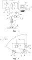
- a coordinate measuring machine 10 is shown purely in principle, which is equipped with the sensor or sensors required for the respective solution of a measuring task.
- the sensors can optionally be mounted or dismantled or even during operation using appropriate sensor replacement systems can be changed in and out automatically. This enables flexible measurement of complex workpiece geometries.
- the invention is not abandoned if a corresponding number of selected sensors are left permanently mounted on the device in order to measure objects in this configuration.
- a coordinate measuring machine 10 comprises a z. B. consisting of granite base frame 12 with measuring table 14 on which an object 16 to be measured is positioned in order to measure its surface properties.
- a portal 18 is adjustable in the Y direction along the base frame 12.
- columns or stands 20, 22 are slidably supported on the base frame 12.
- a traverse 24 extends from the columns 20, 22, along which a slide can be moved, which in turn receives a quill or column 26 which is adjustable in the Z direction.
- a sensor 30 emanates from the quill 26 or possibly an interchangeable interface 28 connected to the quill 26, which in the exemplary embodiment is designed as a tactile sensor which, when the quill 26 contains an image processing sensor, measures optically and optically.
- the coordinate measuring machine 10 can have a sensor changer, as in principle the Fig. 2 can be found.
- Several sensors can each optionally be provided with the coordinate measuring machine via an interchangeable interface and exchanged by hand or by automatically picking up the coordinate measuring machine at a parking station.
- a section of a coordinate measuring machine with a quill 32 is shown in plan view.
- the sensors that can be connected to the quill are identified by the reference numerals 34, 36, 38.
- the sensors 34, 36, 38 can be designed optically or tactilely, to name only exemplary sensor types.
- the coordinate measuring machine, ie the quill 32 can be adjusted in the YXZ direction in such a way that the sensors 34, 36, 38 can be exchanged.
- the quill 32 and thus the coordinate measuring machine positions the sensor 34 in a parking station 42 on a positioning path 40 and is then able to pick up one of the sensors 36, 38 stored in the parking station 42 and attach it again to the quill 32.
- the parking station 42 or the probe changer system can be adjusted by an adjustment axis 44 such that the probe changer 42 is arranged outside the measuring volume of the coordinate measuring machine when it is not in operation.
- the camera of the image processing sensor is selected with a greater resolution (number of pixels) than the resolution of the monitor used or the monitor section used for the image display. Furthermore, the camera can be equipped with random access to certain sections of the overall image. It is then possible for only a section of the overall image to be displayed in the live image or observation image of the coordinate measuring machine, which is enlarged to the format of the respective display window or monitor. As a result, the user has the option of selecting zoomed sections of the image according to his ideas.
- the magnification between the measurement object and the monitor image can be controlled by the software by changing the selected section of the camera image, or the live image can also be displayed in the same way.
- the magnification between the measurement object and the monitor image can be changed by changing the selected section of the camera image. This can be done if necessary by a rotary knob in the control system of the coordinate measuring machine is integrated, or can be operated via a software controller. It is also possible that when using a high-resolution camera, the image or the image section is only displayed in the lower resolution of the monitor, but the full resolution of the camera is used in the background for digital image processing in order to increase the accuracy.
- the actual optical magnification of the imaging optics of the image processing is relatively low (typically 1-fold, but at most 5-fold) and by displaying only a section of the high-resolution camera image on the lower-resolution monitor, the optical effect of a higher magnification is achieved.
- a section of a coordinate measuring machine is arranged.
- the object 16 to be measured is thus shown on the measuring table 12.
- An imaging lens 46 and a camera such as a CCD camera 48, which is connected to a monitor 52 via a computer 50, are arranged above the measurement object 16.
- the hardware of the computer 50 makes it possible to computationally adjust the resolution between the camera 48 and the monitor 52 in order to, for. B. to use a larger camera resolution than can be displayed by the monitor 52. It is also possible here to access certain sections of the overall image with random access or to display the live or observation image of the coordinate measuring machine only as a section of the overall image enlarged to the format of the display window.
- the camera 58 is equipped with additional post-magnification optics 62 in order to define the image scale.
- the optical splitters or mirrors used in the beam path in the Fig. 3 with the reference numerals 56 and 64 are designed so that, after the division, all the cameras 48, 58 or sensors 60 concerned are equipped with the same light intensity.
- An integrated bright-field incident light is implemented via a further optical splitter 66 and an illumination device 68.
- an even higher resolution camera image can be displayed by re-sampling from the respective captured camera image with the purpose of displaying an even higher magnification. In this case, additional pixels are calculated by interpolation between actually measured pixels.
- a problem with known coordinate measuring machines is that programs for measuring workpieces that have been generated once are to be subsequently changed or additional features are to be generated from the measurement results that have already been obtained. According to the current state of the art, this is not possible because the corresponding technology data is no longer available.
- the measuring points or video images or X-ray images measured with one or more sensors of the coordinate measuring machine as well as their associated position and other technology parameters such as the setting value of the lighting system used, light intensity or magnification of the objective of the coordinate measuring machine used during the measurement process recorded, saved and made available for later evaluation.
- Analogous to this described procedure it is also possible that several partial images of a measurement object are measured individually with the image processing sensor and to form an overall image of the overall measurement object or an overall image of
- Sub-areas of the entire measurement object can be joined together.
- This image can be saved and later evaluated on a separate workstation.
- the calibration parameters of the coordinate measuring machine used for image recording are also saved and used again when the software is evaluated. In principle, this should be based on the Fig. 4 explained.
- a measurement object 68 is to be measured with an image processing sensor.
- the reference numerals 70, 72, 76, 78 show image sections which are recorded at different positions in the X, Y coordinate system 80 of the coordinate measuring device on the measurement object 68.
- the image contents of the object sections captured at the respective positions are saved, as well as the associated image processing evaluation windows 82, 84, 86, 88 as well as the parameters stored in the coordinate measuring machine such as magnification of the lens used, setting value of the used Lighting system.
- the actual measurement of the image content and the link e.g. B. the measurement of an angle 90 or a distance 92 take place.
- the software recognizes this automatically and in the exemplary embodiment defines four positions 102, 104, 106, 108, which are measured one after the other in order to combine an overall image and to record the feature to be measured, i.e. the bore 96 in the exemplary embodiment.
- measurement points on the measurement object lying inside the outer contour can optionally be detected by rastering with an image processing sensor and / or scanning with other sensors.
- a measurement object 110 lies on the measurement table 12.
- An image processing sensor used for the measurement has an evaluation area 112.
- the basic position of the measurement object 110 on the measuring table 12 is recognized by changing the image content.
- an outer contour scanning of the measurement object 110 begins until the outer contour is completely captured along the path 118 (contour tracking).
- a grid-shaped capture of the inner area of the measurement object 110 in the previously defined outer limits 120 is carried out, so that the entire measurement object 118 is then available for evaluation.
- Measurement of the intensity for the associated setting value recorded with the image processing sensors Corresponding measurement results are saved as a characteristic curve in the computer of the measuring device.
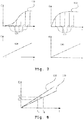
- FIG. 7 an original light characteristic curve 122 of a lighting system for an optical coordinate measuring machine is shown at the top left.
- the lighting intensity E does not depend linearly on the current flow I through the lighting source.
- Fig. 8 shows the procedure for regulating the light intensity E.
- image processing sensors are taught in by the combination of coordinate measuring machine with measurement object in the z. B. incident light a light characteristic 132 effective.
- the setpoint value of the lighting intensity E s is set by the lighting current I 1 . If another measurement object or a different location on the measurement object is measured, the reflection properties of the material may have changed, which leads to a change in the rise in the characteristic light curve.
- This second light characteristic 133 is also shown in FIG Fig. 8 shown. If the lighting intensity is now measured after setting the current I 1 , the lighting intensity E 1 is determined as the result. This does not correspond to the setpoint E s .
- the necessary current I s can be calculated in a simple manner in order to set the target actual strength E s .
- the physical structure for the process described above is the Fig. 2 can be seen in which the light source 68, the mirror 66 and the lens 46 represent the lighting device. The calculation takes place via the computer 50.
- the reflection behavior of the measurement object 16 is different within the measurement objects and generates the different reaction to current I and lighting intensity E.
- the length of contour sections according to the target length while maintaining the curvature or, alternatively, the contour curvature while maintaining the The contour length on the actual contour is changed so that an optimal overlap with the target contour is achieved. If parts with excellent geometrical features are difficult to check due to elasticity or deformation, this process can be supported by the fact that the fit between the actual and target contours on a group of actual and target contours on individually distinguished features, such as intersection points of contours or Circular structures or other recurring structures takes place and so a distortion of the actual contour is generated for optimal overlap with the target contour.
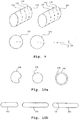
- Fig. 9 is intended to make it clear in principle that the actual contour is partially rotated or screwed in a cylinder jacket surface for optimal overlap with the target contour.
- a point cloud is shown with the reference numeral 134, which is essentially represented by a cylindrical lateral surface. Due to the distortion of the measurement object, the structures on this cylindrical lateral surface are twisted or twisted with respect to one another along the cylinder axis. This twist is mathematically compensated for by turning the structures back to their starting position. This is achieved by comparing the respective sections of the measurement point cloud transversely to the cylinder axis using a target / actual comparison with corresponding target data, and from this the necessary rotational position for the respective section is calculated.
- the reference numeral 134 represents the measurement point cloud of a measurement object having a cylindrical shape.
- the measurement point cloud 134 is shown with a twist, with different degrees of twist being present in the sections 136, 138, 140.
- a setpoint position 142 is compared with an actual point position 144 and the angle of rotation 146 is calculated from this. This is the procedure for the various cuts 136, 138, 140 and the measuring points between them are interpolated.
- the result is a measurement point cloud with distortion correction in the cutting planes 136, 138, 140.
- the corrected cutting planes are shown in FIG Fig. 9 marked with the reference numeral 148, 150, 152 at the top right. It is thus possible, for. B. define the evaluation windows for subsequent image processing sensors at the locations assigned to the structures corresponding target data.
- the point cloud corrected to form the point cloud 134 is provided with the reference symbol 154.
- Fig. 10 a shows an example of how, from an actual contour 156, by changing the curvature while maintaining the length, a better overlap with a nominal contour 158 can be produced for the subsequent comparison with this.
- Circle 160 here shows that a change in curvature with a constant length (in this case the circumference) enables a better adaptation to the desired contour 158.
- FIG 10b it is shown how, while maintaining the curvature of the contours, by changing the length of contour sections, a better overlap between the setpoint / actual value is made possible for the purpose of later comparison.
- the actual contour is shown with the reference numeral 162 and the desired contour is shown with the reference numeral 164.
- the contour 166 is the actual contour adapted to the desired contour 164 by stretching while maintaining the curvature.
- the tolerance zones assigned to the target or actual contour can be evaluated.
- the tolerance zones are automatically taken from the dimensions of a CAD drawing or, alternatively, defined by operator information. Based on the explanations for the Figures 11 and 12 the procedure should be described in more detail.
- a workpiece 167 consisting of the elements 1 to 6 with associated dimensions (dimension 1 to dimension 4) and the tolerances associated with the dimensions reproduced.
- the corresponding dimensions and tolerances can be taken from a CAD drawing, but alternatively can also be defined by operator input.
- a two-sided, symmetrical tolerance zone is assigned, which can have different widths per element. From the Fig. 11 It can be seen that element 1 must be assigned two tolerance zones of different widths by means of dimension 2 with respect to element 3 and by dimension 4 with respect to element 5. Similarly, element 2 can be assigned different tolerance zones with regard to element 4 by specifying dimension 3 and with regard to element 6 by specifying dimension 1.
- the calculation and assignment of the different tolerance zones to the elements takes place automatically by analyzing all reference dimensions that are defined for an element within the drawing and by automatically subdividing the tolerance zones per drawing element according to the reference dimensions available for the element.
- the upper tolerance zone is created by the tolerance assigned to dimension 2
- the lower tolerance zone is created by the tolerance assigned to dimension 4.
- two tolerance zones are assigned to element 2, the in Fig. 12
- the left tolerance zone shown for element 2 arises from the tolerance zone assigned to dimension 1
- the right tolerance zone for element 2 arises from the tolerance zone assigned to dimension 3.
- the measurement points recorded on the real workpiece 166 are assigned to one of the automatically determined tolerance zones according to their position.
- the measuring points assigned to the respective tolerance zones are fitted as best as possible into the tolerances defined around the target contour in the workpiece 166 without binding degrees of freedom, the fitting conditions being selected automatically depending on the type of tolerance.
- the corresponding check for tolerance zone evaluation takes place sequentially for all tolerance zones and all measuring points assigned to these tolerance zones.
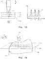
- Each maximum of the contrast characteristic curve represents the location of the respective semi-transparent boundary layer between different types of material layers, and the correspondingly assigned Z positions Z1, Z2 and Z3 can then be calculated from this contrast curve 174.
- the usual methods for contrast autofocus measurement are used here.
- contours on workpiece surfaces are scanned in the sensor direction, ie the coordinate measuring machine is moved on a predetermined path in a direction different from the sensor measuring direction. It is now provided that the position control of the sensor or the position control loop of the coordinate measuring machine is controlled as a function of the deflection display of the laser distance sensor in such a way that the deflection of the laser distance sensor remains constant. This makes it possible to scan contour lines on a measurement object.
- a corresponding contour line scanning is based on the Fig. 14 made clear.
- a measurement object 176 lies on a measuring table of a coordinate measuring machine and is scanned with a distance sensor such as a laser distance sensor 178 of the coordinate measuring machine.
- the movement of the laser distance sensor 178 is controlled in such a way that the distance to the material surface is constant.
- the Z position of the sensor 178 is kept constant and controlled the X and Y position achieves that the sensor measuring point always remains in a plane 180 and thus a contour line 182 on the measuring object 176 is scanned.
- Coordinate measuring machines with various sensors also optionally have sensors with an opto-tactile button.
- the position of the shaped probe element is determined by an image processing sensor.
- the problem is to adjust this sensor to the position of the stylus ball. This can be achieved by additionally arranging an adjustment unit on the coordinate axis carrying the sensor, which enables a relative adjustment between the shaped probe element (probe ball including probe pin and holder) in the image processing sensor. Automatic focusing of the shaped probe element in relation to the image processing sensor is then possible, for example via an autofocus method.
- a tactile-optical sensor 210 also called opto-tactile sensor
- a coordinate measuring device on an adjustment axis 208, which is placed on a coordinate axis of the coordinate measuring device, preferably the Z-axis 208, which in the exemplary embodiment is the optical axis of an optical sensor 210 coincides.
- adjusting device 210 By separately controlling a second Z-axis (adjusting device 210), it is possible to adjust the relative position between the shaped probe element 212 of the tactile-optical sensor 206 and the focal plane 214 of the optical sensor 210 in a targeted manner.
- Coordinate measuring machines are generally exposed to different operating temperatures at the place of use. If several sensors are attached to the coordinate measuring machine, this means that the positions between the various sensors change due to thermal factors. This leads to measurement errors. To compensate for this, the temperature of the mechanical assemblies required to attach the various sensors is measured at one or more points and the expansion of the corresponding mechanical components are taken into account when calculating the measuring points recorded by the various sensors.
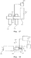
- Fig. 17 an example of an arrangement with two sensors 218, 220 on a Z-axis 222 of a coordinate measuring machine.
- the sensors 218, 220 are one or more connecting elements 224 connected to one another and to the Z-axis 222.
- a temperature sensor 226 continuously measures the temperature of the connection element (s) 224 during the measurement and an evaluation computer 228 corrects the corresponding change in length and takes it into account for the measurement results.
- an evaluation computer 228 corrects the corresponding change in length and takes it into account for the measurement results.
- the measurement object can be clamped in an axis of rotation and thus rotated into an optimal position for the measurement with the various sensors.
- the measurement object in addition to the axis of rotation itself with a correspondingly arranged counter-tip.
- the problem arises that the clamping force of the counter-tip can lead to deformation of the object to be measured.
- the measurement object be constantly deformed or that the counter-tip be automatically positioned on the measurement object until a predefined force is reached.
- the counter-tip can be spring-mounted so that the required force can be determined via a deflection and a corresponding limit switch.
- Fig. 18 How when clamping a measuring object 230 tip 232 and counter-tip 234 are pushed up to a point by a guide 236 against the measuring object 230 until the counter-tip 234 interacts with a limit switch 238.
- a bias can be generated by means of a bias spring 240, the feed movement (arrow 242) of the counter tip 234, which is achieved by a corresponding drive 244 on the guide 236, is then interrupted when the counter tip 234 on the limit switch 238 or an equivalent Element acts. This clearly defines the pretensioning force of the clamped measurement object 236.
- Fig. 19 shows an example.
- Several tactile sensors 248, 250, 252 are arranged on a common Z-axis 254 of a coordinate measuring device. When a measurement object 256 is touched, measurement points 258, 260, 262 for different positions are measured at the same time, which are then jointly evaluated in the coordinate measuring machine.
- a laser distance sensor is additionally integrated in the image processing beam path.
- the laser sensor measures the distance between the image processing sensor and the workpiece surface near the outer edge to be measured and is connected to a position control loop of the coordinate measuring machine in such a way that automatic tracking takes place.
- the image processing sensor is thus permanently focused. This is done using the Fig. 20 clarified in principle.
- Two sensors 260, 262 combined with one another for image processing and laser distance measurement are combined on a Z-axis 258 of a coordinate measuring machine, which sensors detect measuring points on a tool 266 via a common optical system 264.
- the axis of rotation 268 of the tool 266 is controlled by a computer and control system 270 of the coordinate measuring machine, which also has the sensor signals from the coordinate measuring machine, in such a way that the measuring points measured with the laser distance sensor 262 on a rake face 272 of the tool 266 influence the settings of the axis of rotation 268 that the cutting edge comes to rest in each case in the section plane 274 of the tool at this location.
- the image processing sensor 260 of the same coordinate measuring machine it is possible to measure the outer contour of the corresponding tool. With constant turning and traversing of the X, Y and Z axes With the coordinate measuring machine, this process can be repeated continuously and scanning can thus be carried out in all three coordinates at the same time.
- Image processing sensors with laser sensors integrated in the beam path can be used in a coordinate measuring machine.
- the desired optical properties for the integrated laser distance sensor and the image processing sensor are not present with the same setting parameters (working distance / magnification).
- the aperture and working distance of the zoom optics system used can be optimized for the laser sensor and the image processing sensor as an alternative.
- FIG. 21 an image processing sensor 276 and a laser distance sensor 278 are shown, which are used via a beam splitter 280 with a common measuring objective 282 in a coordinate measuring machine.
- a measurement object 284 is to be touched, that is to say, in the present case, to be measured without contact.
- an additional upstream optics 286, which can be stored in a changing station 288, it is possible to change the optical properties of the overall beam path. This is determined by the measuring objective 282 and with the upstream optics 286 located or not located in its beam path.
- the setting parameters for the laser distance sensor 278 with the upstream optics 286 or for the image processing sensor 276 with the upstream optics 286 removed, or vice versa can take place.
- the measuring points are usually specified by the operator in teach-in mode. If unknown contours are to be measured using this method, this is difficult to do.
- a scanning process of a material surface be carried out with an autofocus sensor in that the probable location of the next measuring point is theoretically calculated from the already measured focus points by extrapolation and is precisely remeasured using a new autofocus point. Will this process multiple times repeated one after the other, the result is a fully automatic scanning.
- Both the number of points to be scanned along a line and an area to be scanned on the workpiece or measurement object can be specified by the operator.
- the extrapolation of the next measuring point from the two or more previous measuring points can be done by a linear extrapolation.
- Fig. 22 a corresponding method for scanning a material surface with an autofocus sensor.
- An autofocus sensor 290 is used in a first location 191 by moving in the Z-axis of the coordinate measuring machine to measure a point on the surface.
- the contrast behavior is recorded over a focus area 292 and from this the focus location 294 is calculated in accordance with the measurement point.
- the same process is repeated at a next position 295 with a corresponding focus measurement area 296 and measurement point 298.
- an X-ray source 308, a turntable 310 with a measurement object 312 and an X-ray sensor 314 are shown.
- the pixel amplitude of the X-ray detector 314 is stored in a computer and evaluation system 316 and evaluated and combined in accordance with the previously explained method steps. It is possible to control the X-ray frequency of the radiation source 308 and the recording parameters of the detector 316 by the evaluation system 316 in accordance with the procedure described.
Description
Die Erfindung bezieht sich auf ein Verfahren zum Messen von Werkstückgeometrien mit einem Koordinatenmessgerät mit beweglichen Verfahrachsen und zumindest einem Bildverarbeitungssensor oder einem Röntgensensor zur Erfassung von Messpunkten auf den Werkstückoberflächen, wobei jeweils derjenige Sensor entsprechend der zu lösenden Messaufgabe zum Messen der Werkstückgeometrien ausgewählt wird.The invention relates to a method for measuring workpiece geometries with a coordinate measuring machine with movable axes and at least one image processing sensor or an X-ray sensor for detecting measuring points on the workpiece surfaces, the sensor being selected for measuring the workpiece geometries in accordance with the measuring task to be solved.
Unter Koordinatenmessgeräten werden Messgeräte mit einer oder mehreren mechanisch bewegten Achsen zur Messung von geometrischen Eigenschaften von Werkstücken bzw. Messobjekten verstanden. Diese Koordinatenmessgeräte sind mit Sensoren zur Aufnahme der geometrischen Messpunkte an den Werkstückoberflächen ausgestattet. Stand der Technik sind überwiegend Koordinatenmessgeräte mit rein taktilen Sensoren, d. h. der Messpunkt wird durch Berührung der Werkstückoberfläche mit einem taktilen Fühler erzeugt. Ebenfalls bekannt sind Koordinatenmessgeräte mit optischen Sensoren, bei denen die Messpunkte durch eine opto-elektronische Bildverarbeitung oder einen Laserabstandssensor ermittelt werden. Es sind ebenfalls Koordinatenmessgeräte bekannt, bei denen einzelne dieser Sensoren miteinander kombiniert und so erweiterte Möglichkeiten für den Anwender gegeben sind.Coordinate measuring machines are understood to mean measuring machines with one or more mechanically moved axes for measuring geometric properties of workpieces or objects to be measured. These coordinate measuring machines are equipped with sensors for recording the geometric measuring points on the workpiece surfaces. State of the art are predominantly coordinate measuring machines with purely tactile sensors, i. H. the measuring point is generated by touching the workpiece surface with a tactile sensor. Also known are coordinate measuring machines with optical sensors in which the measuring points are determined by opto-electronic image processing or a laser distance sensor. Coordinate measuring machines are also known in which some of these sensors are combined with one another, thus providing the user with expanded options.
Ein Überblick über die Koordinatenmesstechnik ergibt sich aus den Literaturstellen
Immer wieder ist es festzustellen, dass das zum Einsatz gelangende Koordinatenmessgerät für die jeweilige Messaufgabe nicht optimal konfiguriert ist, so dass folglich mehrere Geräte verschiedener Bauarten notwendig sind.Again and again it has to be stated that the coordinate measuring machine used is not optimally configured for the respective measuring task, so that consequently several devices of different types are necessary.
Der
Aus der
Der vorliegenden Erfindung liegt das Problem zugrunde, ein Verfahren zum Messen von Werkstückgeometrien mit einem Koordinatenmessgerät derart weiterzubilden, dass Einzelmessergebnisse derart verarbeitet werden, dass eine präzise Messung der Werkstückgeometrien möglich wird.The present invention is based on the problem of developing a method for measuring workpiece geometries with a coordinate measuring machine in such a way that individual measurement results are processed in such a way that precise measurement of the workpiece geometries is possible.
Zur Lösung der Aufgabe sieht die Erfindung ein Verfahren gemäß Anspruch 1 vor.To achieve the object, the invention provides a method according to
Zur Verbesserung des Signalrauschverhältnisses von Bildverarbeitungssensoren oder Röntgensensoren kann die Integrationszeit so lange verlängert werden, bis ein ausreichend hohes Signalrauschverhältnis vorliegt. Dies bedeutet, dass mehrere aufeinander folgende Bilder addiert werden und dann an diesem aufaddierten Bild die Bildauswertung erfolgt. Dieser Vorgang kann automatisch geregelt werden, in dem die Integrationszeit einer solchen Kamera so lange verlängert wird, bis ein ausreichend gutes Bild gespeichert und weiter verarbeitet werden kann. Die Intensität der Bildpunkte des Bildes wird hierbei bis zu einem Sollwert überwacht und durch Aufspeichern mehrerer Bilder vergrößert.To improve the signal-to-noise ratio of image processing sensors or X-ray sensors, the integration time can be extended until a sufficiently high signal-to-noise ratio is present. This means that several consecutive images are added and then the image evaluation is carried out on this added image. This process can be regulated automatically by extending the integration time of such a camera until a sufficiently good image can be saved and processed further. The intensity of the pixels of the image is monitored up to a target value and enlarged by storing several images.
Beim Messen mit Bildverarbeitungssensoren in Koordinatenmessgeräten werden verschiedene Beleuchtungsquellen, wie Hellfeld, Dunkelfeld, Durchlicht, eingesetzt, um jeweils optimale Kontrastverhältnisse für Teilbereiche eines zu messenden Werkstückes zu erreichen. Diese Beleuchtungsquellen werden hinsichtlich ihrer Einstellung, wie Intensität, Raumwinkel der Beleuchtung (Beleuchtungswinkel oder Richtung der Beleuchtung), Beleuchtungsrichtung variiert, um optimale Verhältnisse zu erreichen. Diese Parameter sind für Teilbereiche des zu messenden Objektes jeweils unterschiedlich, weshalb es nicht möglich ist, mit einer Beleuchtungseinstellung das gesamte Objekt optimal abzubilden. Um diesen Nachteil zu vermeiden, wird vorgeschlagen, dass zur Erzeugung eines optimalen kontrastierten Bildes nacheinander mehrere Bilder mit verschiedenen Beleuchtungsquellen aufgenommen und aus jedem Bild jeweils die Bereiche mit optimalem Kontrast entnommen und zu einem geometrisch richtigen Gesamtbild zusammengefügt werden.When measuring with image processing sensors in coordinate measuring machines, various sources of illumination, such as bright field, dark field, transmitted light, are used in order to achieve optimal contrast ratios for partial areas of a workpiece to be measured. These lighting sources are varied with regard to their setting, such as intensity, solid angle of the lighting (lighting angle or direction of the lighting), and the direction of lighting in order to achieve optimal conditions. These parameters are different for partial areas of the object to be measured, which is why it is not possible to optimally depict the entire object with one lighting setting. In order to avoid this disadvantage, it is proposed that, in order to generate an optimally contrasted image, several images be taken one after the other with different lighting sources and the areas with optimal contrast are taken from each image and combined to form a geometrically correct overall image.
Es ist vorgesehen, dass zur Erzeugung eines optimalen Kontrasts für den Bildverarbeitungssensor nacheinander mehrere Bilder mit verschiedenen Beleuchtungsquellen aufgenommen, aus jedem Bild die Bereiche mit optimalem Kontrast entnommen und zu einem kontrastoptimierten Gesamtbild zusammengefügt werden.It is provided that, in order to generate an optimal contrast for the image processing sensor, several images are taken one after the other with different illumination sources, the areas with optimal contrast are removed from each image and combined to form a contrast-optimized overall image.
Im Detail ist es somit möglich, dass verschiedene Bilder des gleichen Objektes bzw. Objektausschnittes durch Verwendung verschiedener Beleuchtungsrichtungen einer Dunkelfeldbeleuchtung und/oder verschiedener Beleuchtungswinkel einer Dunkelfeldbeleuchtung und/oder Einsatz einer Hellfeldbeleuchtung aufgenommen und die kontrastoptimalen Bereiche des Einzelbildes zu einem optimierten Gesamtbild zusammengefügt werden. Dieses kann dann anschließend messtechnisch ausgewertet werden. Die beschriebene Vorgehensweise kann ebenfalls auf jedes einzelne Pixel des Bildverarbeitungssensors angewendet werden, d. h. dass für jedes Pixel des resultierenden Gesamtbildes das Pixel mit optimalem Kontrast aus der Anzahl von Einzelbildern heraus gewählt wird. Der Kontrast eines Einzelpixels wird durch die Amplitudendifferenz dieses Pixels zu seinen Nachbarn im Bild bestimmt.In detail, it is thus possible that different images of the same object or object section are recorded by using different lighting directions of dark field lighting and / or different lighting angles of dark field lighting and / or the use of bright field lighting and the contrast-optimal areas of the individual image are combined to form an optimized overall image. This can then be evaluated using measurement technology. The procedure described can also be applied to each individual pixel of the image processing sensor, that is to say that for each pixel of the resulting overall image, the pixel with optimal contrast from the number of individual images is chosen. The contrast of an individual pixel is determined by the difference in amplitude between this pixel and its neighbors in the image.
Es ist vorgesehen, dass für jedes Pixel des resultierenden Gesamtbildes bzw. für jeden Ort jedes resultierenden Pixels des Gesamtbildes dasjenige Pixel mit gleichem Ort aus den mit verschiedener Beleuchtung generierten Einzelbildern ausgewählt wird, welches optimalen Kontrast in seiner Umgebung aufweist, wobei die Bewertung des optimalen Kontrasts durch Bestimmung der Amplituden-Differenz zwischen den jeweils betrachteten Pixeln und den benachbarten Pixeln durchgeführt wird.It is provided that for each pixel of the resulting overall image or for each location of each resulting pixel of the overall image that pixel with the same location is selected from the individual images generated with different lighting, which has optimal contrast in its surroundings, the evaluation of the optimal contrast is carried out by determining the amplitude difference between the pixels under consideration and the neighboring pixels.
Beim Einsatz von Bildverarbeitungssensoren oder Röntgentomographiesensoren tritt das Problem auf, dass je nach Eigenschaften des Messobjektes innerhalb eines Bildes sowohl Bereiche mit starken als auch mit schwachen Intensitäten vorliegen. Dies wird durch die unterschiedlichen Reflexions- bzw. Transmissionseigenschaften der Materialien verursacht. Im Ergebnis sind für die "dunklen" Bildbereiche nur geringe Signale vorhanden mit daraus folgendem schlechten Signal/Rausch-Verhältnis. Eine stärkere Beleuchtung bzw. Bestrahlung des Objektes würde jedoch zum Überstrahlen in den hellen Bereichen führen und schließt sich somit aus.When using image processing sensors or X-ray tomography sensors, the problem arises that, depending on the properties of the measurement object, there are areas with both strong and weak intensities within an image. This is caused by the different reflection and transmission properties of the materials. As a result, only low signals are present for the "dark" image areas, with the resulting poor signal / noise ratio. However, a stronger illumination or irradiation of the object would lead to overexposure in the bright areas and is therefore excluded.
Das beschriebene Problem wird dadurch gelöst, dass zu jedem Bildausschnitt mehrere Bilder mit unterschiedlichen Beleuchtungsintensitäten aufgenommen werden. Anschließend werden diese Bilder des gleichen Objektbereiches in der Weise zu einem neuen Gesamtbild zusammengefügt, dass die Bildpunktamplituden auf die jeweilige Beleuchtungs- bzw. Strahlungsintensität, die verwendet wurde, normiert werden. Zur Gesamtbildzusammensetzung werden anschließend die Pixel aus dem jeweiligen Bild verwendet, die innerhalb des zugelassenen Dynamikbereiches (z. B. 0 - 245 bei 8 Bit) liegen. Amplituden mit Überstrahlung werden aus dem jeweiligen Bild nicht berücksichtigt (z. B. > 245). Für Pixel mit mehreren gültigen Bildpunktamplituden erfolgt eine Mittelung aus den Werten. Anschließend kann das Gesamtbild ausgewertet werden.The problem described is solved in that a plurality of images with different lighting intensities are recorded for each image section. These images of the same object area are then combined to form a new overall image in such a way that the pixel amplitudes are normalized to the respective illumination or radiation intensity that was used. The pixels from the respective image that are within the permitted dynamic range (e.g. 0 - 245 for 8 bits) are then used to compose the overall image. Amplitudes with overexposure are not taken into account from the respective image (e.g.> 245). For pixels with several valid pixel amplitudes, the values are averaged. The overall picture can then be evaluated.
Sowohl bei Einsatz von Bildverarbeitungssensoren als auch in Röntgentomographie-Anwendungen reicht oft die Strahlungsintensität bzw. Durchstrahlungsintensität des Messobjekts nicht aus, um eine optimale Messung zu ermöglichen. Dies wird dadurch verbessert, dass zur Qualitätsoptimierung von aufgenommenen Bildern bei Bildverarbeitungssensoren bzw. Röntgentomographiesensoren mehrere Bilder eines Objektbereiches mit jeweils unterschiedlichen Beleuchtungs- bzw. Strahlungsintensitäten aufgenommen und diese dann zu einem Gesamtbild zusammengefügt werden. Es werden zum Beispiel aus jedem Einzelbild einer mit jeweils unterschiedlicher Beleuchtungs- bzw. Strahlungsintensität aufgenommenen Einzelbilderschar die Bildpunktamplituden (Pixel) herangezogen, die innerhalb eines als gültig definierten Amplitudenbereiches (typisch zwischen 0 und 245 LSB) liegen. Bildpunktamplituden mit Amplitudenwertung, die auf Überstrahlung schließen lassen (z. B. > 245 LSB) bleiben bei der Auswertung unberücksichtigt. Liegen aus mehreren Bildern gültige Bildpunktamplituden zu einem Bildpunkt vor, kann aus den normierten Bildpunktamplituden ein Mittelwert gebildet werden. Es ist möglich, alle beschriebenen Berechnungen auf die benutzte Strahlungs- bzw. Beleuchtungsintensität normierten Amplitudenwerte durchzuführen.When using image processing sensors as well as in X-ray tomography applications, the radiation intensity or radiation intensity of the measurement object is often insufficient to enable an optimal measurement. This is improved by helping to optimize the quality of recorded images Image processing sensors or X-ray tomography sensors record a plurality of images of an object area with each different illumination or radiation intensities and these are then combined to form an overall image. For example, the image point amplitudes (pixels) that lie within an amplitude range defined as valid (typically between 0 and 245 LSB) are used from each individual image of a group of individual images recorded with different illumination or radiation intensity. Pixel amplitudes with amplitude evaluation that indicate over-exposure (e.g.> 245 LSB) are not taken into account in the evaluation. If valid pixel amplitudes for a pixel are available from several images, a mean value can be formed from the normalized pixel amplitudes. It is possible to carry out all the calculations described for amplitude values standardized for the radiation or lighting intensity used.
Weitere Einzelheiten, Vorteile und Merkmale der Erfindung ergeben sich nicht nur aus den Ansprüchen, den diesen zu entnehmenden Merkmalen für sich und/oder in Kombination, sondern auch aus der nachfolgenden Beschreibung von der Zeichnung zu entnehmenden bevorzugten Ausführungsbeispielen.Further details, advantages and features of the invention emerge not only from the claims, the features to be taken from them individually and / or in combination, but also from the following description of preferred exemplary embodiments to be taken from the drawing.
Es zeigen:
- Fig. 1
- eine Prinzipdarstellung eines Koordinatenmessgerätes,
- Fig. 2
- einen Ausschnitt eines Koordinatenmessgerätes in Prinzipdarstellung,
- Fig. 3
- eine Prinzipdarstellung eines Koordinatenmessgerätes mit Bildverarbeitungs- und Laserabstandssensor,
- Fig. 4
- eine Prinzipdarstellung eines Messverfahrens,
- Fig. 5
- eine weitere Prinzipdarstellung eines Messverfahrens,
- Fig. 6
- eine Prinzipdarstellung einer Konturverfolgung,
- Fig. 7
- Lichtintensitätskurven,
- Fig. 8
- eine Soll- und eine Ist-Lichtintensitätskurve,
- Fig. 9
- Soll- und Ist-Vergleich von Konturdaten,
- Fig. 10a, 10b
- Soll- und Ist-Konturen,
- Fig. 11, 12
- ein Messobjekt mit Toleranzzonen,
- Fig. 13
- eine Anordnung zum Messen teiltransparenter Schichten,
- Fig. 14
- eine Messanordnung zum Messen eines Höhenprofils,
- Fig. 15
- eine Messanordnung zum Messen eines Messobjektes in unterschiedlichen Stellungen,
- Fig. 16
- eine Anordnung zur Bestimmung der Lage eines Antastformelementes,
- Fig. 17
- eine Anordnung mit zwei miteinander verbundenen Sensoren,
- Fig. 18
- eine Einspannanordnung für ein Messobjekt,
- Fig. 19
- einen Sensorrechen zur Messung mehrerer Messbahnen,
- Fig. 20
- eine Anordnung zur Messung eines Werkzeuges,
- Fig. 21
- eine Messanordnung mit Bildverarbeitungssensor und Laserabstandssensor,
- Fig. 22
- ein Prinzipbild zur Messung von durch Extrapolation ermittelten Messpunkten und
- Fig. 23
- eine Prinzipdarstellung einer Anordnung mit einem Röntgentomographiesensor .
- Fig. 1
- a schematic representation of a coordinate measuring machine,
- Fig. 2
- a section of a coordinate measuring machine in a schematic diagram,
- Fig. 3
- a schematic diagram of a coordinate measuring machine with image processing and laser distance sensor,
- Fig. 4
- a schematic representation of a measurement process,
- Fig. 5
- a further schematic diagram of a measurement process,
- Fig. 6
- a schematic representation of a contour tracking,
- Fig. 7
- Light intensity curves,
- Fig. 8
- a target and an actual light intensity curve,
- Fig. 9
- Target and actual comparison of contour data,
- Figures 10a, 10b
- Target and actual contours,
- Figures 11, 12
- a target with tolerance zones,
- Fig. 13
- an arrangement for measuring partially transparent layers,
- Fig. 14
- a measuring arrangement for measuring a height profile,
- Fig. 15
- a measuring arrangement for measuring a measuring object in different positions,
- Fig. 16
- an arrangement for determining the position of a shaped probe element,
- Fig. 17
- an arrangement with two interconnected sensors,
- Fig. 18
- a clamping arrangement for a measurement object,
- Fig. 19
- a sensor rake for measuring several measuring tracks,
- Fig. 20
- an arrangement for measuring a tool,
- Fig. 21
- a measuring arrangement with image processing sensor and laser distance sensor,
- Fig. 22
- a schematic diagram for the measurement of measuring points determined by extrapolation and
- Fig. 23
- a schematic diagram of an arrangement with an X-ray tomography sensor.
Die Erfindung bzw. Erfindungskomplexe werden nachstehend an bevorzugten Ausführungsbeispielen näher erläutert.The invention or complexes of the invention are explained in more detail below using preferred exemplary embodiments.
Die entsprechenden Ausführungen erfolgen dabei vor dem Hintergrund, dass Kenntnisse der Koordinatenmesstechnik präsent sind. Ergänzend wird insoweit auf die Literaturstellen
In
Das hinlänglich bekannte und noch einmal in der
Entlang dem Grundrahmen 12 ist ein Portal 18 in Y-Richtung verstellbar. Hierzu sind Säulen oder Ständer 20, 22 gleitend am Grundrahmen 12 abgestützt. Von den Säulen 20, 22 geht eine Traverse 24 aus, entlang der ein Schlitten verfahrbar ist, der seinerseits eine Pinole oder Säule 26 aufnimmt, die in Z-Richtung verstellbar ist. Von der Pinole 26 bzw. ggfs. einer mit der Pinole 26 verbundenen Wechselschnittstelle 28 geht ein Sensor 30 aus, der im Ausführungsbeispiel als taktiler Sensor ausgebildet ist, der dann, wenn die Pinole 26 einen Bildverarbeitungssensor enthält, taktil-optisch misst. Insoweit wird jedoch auf hinlänglich bekannte Techniken verwiesen, genauso wie in Bezug auf weitere zum Einsatz gelangende Sensoren wie Laserabstandssensor, Weißlichtinterferometer, Bildverarbeitungssensoren, Röntgensensorik oder chromatischer Fokussensor oder konfokal Scanning-Messkopf, ohne dass hierdurch eine Einschränkung der erfindungsgemäßen Lehre erfolgt. Der bzw. die Sensoren werden entsprechend der Messaufgabe ausgewählt und eingesetzt, um das Koordinatenmessgerät 10 für die jeweilige Messaufgabe optimal zu konfigurieren. Gleichzeitig werden Probleme gelöst, die bei üblichen Koordinatenmessgeräten auftreten.A portal 18 is adjustable in the Y direction along the
Um das Koordinatenmessgerät 10 mit dem geeigneten Sensor nutzen zu können, kann das Koordinatenmessgerät einen Sensorwechsler aufweisen, wie dies prinzipiell der
In
Bei Anwendung von Bildverarbeitungssensoren in Koordinatenmessgeräten ist es für den Anwender erforderlich, verschiedene Vergrößerungen einzustellen. Dem widerspricht die Forderung nach kostenoptimierten optischen Systemen sowie hohen Abbildungsgüten, die mit den sonst erforderlichen Zoom-Optiken nur schwer zu erreichen sind. Um diesen Forderungen zu genügen ist vorgesehen, dass die Kamera des Bildverarbeitungssensors mit einer größeren Auflösung (Pixelanzahl) gewählt wird, als die Auflösung des verwendeten Monitors bzw. des für die Bilddarstellung verwendeten Monitorausschnitts. Im Weiteren kann die Kamera mit wahlfreiem Zugriff auf bestimmte Ausschnitte des Gesamtbildes ausgestattet sein. Es ist dann möglich, dass im Live-Bild oder Beobachtungsbild des Koordinatenmessgerätes nur ein Ausschnitt des Gesamtbildes dargestellt wird, der auf das Format des jeweiligen Anzeigefensters bzw. Monitors vergrößert wird. Im Ergebnis hat der Anwender die Möglichkeit gezoomte Ausschnitte des Bildes entsprechend seinen Vorstellungen auszuwählen. Die Vergrößerung zwischen Messobjekt und Monitorbild kann durch Verändern des gewählten Ausschnittes des Kamerabildes durch die Software gesteuert werden oder auch das Live-Bild in gleicher Weise dargestellt werden. Die Vergrößerung zwischen Messobjekt und Monitorbild kann durch Verändern des gewählten Ausschnittes des Kamerabildes verändert werden. Dies kann gegebenenfalls durch einen Drehknopf, der in das Steuerungssystem des Koordinatenmessgerätes integriert ist, oder über einen Softwareregler bedient werden. Es ist fernerhin möglich, dass bei Einsatz einer hochauflösenden Kamera das Bild bzw. der Bildausschnitt nur in der geringeren Auflösung des Monitors angezeigt wird, im Hintergrund jedoch die volle Auflösung der Kamera zur digitalen Bildverarbeitung eingesetzt wird, um die Genauigkeit zu steigern. Die wirkliche optische Vergrößerung der Abbildungsoptik der Bildverarbeitung ist hierbei relativ gering (typisch 1-fach, höchstens jedoch 5-fach) und durch die Darstellung lediglich eines Ausschnittes des hoch auflösenden Kamerabildes auf dem geringer auflösenden Monitor wird die optische Wirkung einer höheren Vergrößerung erreicht.When using image processing sensors in coordinate measuring machines, it is necessary for the user to set different magnifications. This contradicts the demand for cost-optimized optical systems as well as high image quality, which are difficult to achieve with the otherwise required zoom optics. In order to meet these requirements, it is provided that the camera of the image processing sensor is selected with a greater resolution (number of pixels) than the resolution of the monitor used or the monitor section used for the image display. Furthermore, the camera can be equipped with random access to certain sections of the overall image. It is then possible for only a section of the overall image to be displayed in the live image or observation image of the coordinate measuring machine, which is enlarged to the format of the respective display window or monitor. As a result, the user has the option of selecting zoomed sections of the image according to his ideas. The magnification between the measurement object and the monitor image can be controlled by the software by changing the selected section of the camera image, or the live image can also be displayed in the same way. The magnification between the measurement object and the monitor image can be changed by changing the selected section of the camera image. This can be done if necessary by a rotary knob in the control system of the coordinate measuring machine is integrated, or can be operated via a software controller. It is also possible that when using a high-resolution camera, the image or the image section is only displayed in the lower resolution of the monitor, but the full resolution of the camera is used in the background for digital image processing in order to increase the accuracy. The actual optical magnification of the imaging optics of the image processing is relatively low (typically 1-fold, but at most 5-fold) and by displaying only a section of the high-resolution camera image on the lower-resolution monitor, the optical effect of a higher magnification is achieved.
Das zuvor erläuterte Verfahren soll prinzipiell anhand der
Im Ausführungsbeispiel wird die Kamera 58 mit einer zusätzlichen Nachvergrößerungsoptik 62 ausgestattet, um den Abbildungsmaßstab zu definieren. Die im Strahlengang verwendeten optischen Teiler oder Spiegel, die in der
Ein Problem bei bekannten Koordinatenmessgeräten besteht darin, dass einmal erzeugte Programme zum Messen von Werkstücken nachträglich geändert bzw. nachträglich zusätzliche Merkmale aus den bereits gewonnenen Messergebnissen generiert werden sollen. Dies ist nach dem gegenwärtigen Stand der Technik nicht möglich, da die entsprechenden zugehörigen Technologiedaten nicht mehr vorhanden sind. Zur Lösung des Problems ist vorgesehen, dass die mit einem oder mehreren Sensoren des Koordinatenmessgerätes gemessenen Messpunkte bzw. Video-Bilder bzw. Röntgenbilder sowie deren zugehörige Position und andere Technologieparameter wie Einstellwert des verwendeten Beleuchtungssystems, Lichtintensität oder Vergrößerung des verwendeten Objektivs des Koordinatenmessgerätes während des Messablaufs aufgenommen, abgespeichert und für eine spätere Auswertung so zur Verfügung gestellt werden. Analog zu dieser beschriebenen Vorgehensweise ist es ebenfalls möglich, dass mit dem Bildverarbeitungssensor mehrere Teilbilder eines Messobjekts einzeln gemessen und zu einem Gesamtbild des Gesamtmessobjekts oder zu einem Gesamtbild vonA problem with known coordinate measuring machines is that programs for measuring workpieces that have been generated once are to be subsequently changed or additional features are to be generated from the measurement results that have already been obtained. According to the current state of the art, this is not possible because the corresponding technology data is no longer available. To solve the problem, it is provided that the measuring points or video images or X-ray images measured with one or more sensors of the coordinate measuring machine as well as their associated position and other technology parameters such as the setting value of the lighting system used, light intensity or magnification of the objective of the coordinate measuring machine used during the measurement process recorded, saved and made available for later evaluation. Analogous to this described procedure, it is also possible that several partial images of a measurement object are measured individually with the image processing sensor and to form an overall image of the overall measurement object or an overall image of
Teilbereichen des gesamten Messobjekts zusammengefügt werden. Dieses Bild kann gespeichert werden und später auf einem separaten Arbeitsplatz ausgewertet werden. Hierzu werden ebenfalls die Kalibrierparameter des zur Bildaufnahme eingesetzten Koordinatenmessgerätes mitgespeichert und bei der Auswertung der Software erneut eingesetzt. Dies soll prinzipiell anhand der
Ein Messobjekt 68 soll mit einem Bildverarbeitungssensor gemessen werden. Mit den Bezugszeichen 70, 72, 76, 78 sind Bildausschnitte dargestellt, die bei verschiedenen Positionen im X-,Y-Koordinatensystem 80 des Koordinatenmessgerätes am Messobjekt 68 erfasst werden. Zusätzlich zu den eigentlichen X- und Y-Positionen werden die Bildinhalte der an den jeweiligen Positionen erfassten Objektausschnitte abgespeichert, dazu die jeweilig zugehörigen Bildverarbeitungsauswertefenster 82, 84, 86, 88 sowie die hierzu im Koordinatenmessgerät gespeicherten Parameter wie Vergrößerung des verwendeten Objektivs, Einstellwert des verwendeten Beleuchtungssystems. Nach Erfassung all dieser Werte kann auf einem Auswerterechner offline die eigentliche Messung der Bildinhalte und die Verknüpfung, z. B. die Messung eines Winkels 90 oder eines Abstandes 92, erfolgen.A
Für den Fall, dass beim Einsatz eines Bildverarbeitungssensors das Sehfeld der Kamera nicht ausreicht, um das durch Wählen des gewünschten Auswertebereichs (Bildverarbeitungsfenster) definierte Areal des Messobjekts auf einmal zu erfassen, ist vorgesehen, dass automatisch ein Bild aus mehreren Teilen zusammengesetzt wird, das dem Anwender anschließend wie ein gemessenes Bild dargestellt und zur Auswertung zur Verfügung gestellt wird. Dies wird prinzipiell anhand der
Mittels der
- Suchen des Messobjekts im Messbereich des Koordinatenmessgerätes durch Fahren eines Sensors auf einem geradlinigen, spiralförmigen, mäanderförmigen, kreisbogenförmigen oder stochastischen oder anders gearteten Suchweg, bis die Existenz eines Messobjekts detektiert wird, und
- Starten eines Scanning der Außenkontur des Messobjekts (Konturverfolgung zur Erfassung der Geometrie und Lage der Außenkontur des Messobjekts).
- Searching for the measuring object in the measuring range of the coordinate measuring machine by moving a sensor on a straight, spiral, meandering, circular arc or stochastic or other type of search path until the existence of a measuring object is detected, and
- Start a scan of the outer contour of the measuring object (contour tracking to capture the geometry and position of the outer contour of the measuring object).
Ferner können optional im Inneren der Außenkontur liegende Messpunkte auf dem Messobjekt durch Rastern mit einem Bildverarbeitungssensor und/oder Abtasten mit anderen Sensoren erfasst werden.Furthermore, measurement points on the measurement object lying inside the outer contour can optionally be detected by rastering with an image processing sensor and / or scanning with other sensors.
So liegt auf dem Messtisch 12 ein Messobjekt 110. Ein für die Messung benutzter Bildverarbeitungssensor weist einen Auswertebereich 112 auf. Durch Bewegung auf einer z. B. spiralförmigen Bahn 114 wird die prinzipielle Lage des Messobjekts 110 auf dem Messtisch 12 durch Änderung des Bildinhalts erkannt. Beim Auftreffpunkt des Bildverarbeitungssensors mit der Objektkontur (Bereich 116) beginnt ein Außenkontur-Scanning des Messobjekts 110 bis zur vollständigen Erfassung der Außenkontur entlang der Bahn 118 (Konturverfolgung). Danach wird zur vollständigen Erfassung des Gesamtmessobjekts automatisch ein rasterförmiges Erfassen des inneren Bereichs des Messobjektes 110 in den zuvor definierten Außengrenzen 120 durchgeführt, so dass anschließend das Gesamtmessobjekt 118 zur Auswertung zur Verfügung steht.A
Ein Problem beim Einsatz von Koordinatenmessgeräten mit Bildverarbeitungssensoren besteht darin, dass die verschiedenen Beleuchtungssysteme nicht lineare Kennlinien aufweisen. Dies führt u. a. dazu, dass verschiedene Messobjekte nicht richtig gemessen werden können oder Programme von einem auf das andere Gerät nicht ohne Weiteres übertragbar sind. Um dieses Problem zu lösen, wird vorgeschlagen, dass die Kennlinien der Beleuchtungseinrichtungen des Bildverarbeitungssensorsystems des Koordinatenmessgerätes aufgenommen werden, d. h. es wird die Abhängigkeit der Beleuchtungsintensität vom Einstellbild der Bedieneroberfläche des Messgerätes durchOne problem with the use of coordinate measuring machines with image processing sensors is that the various lighting systems have non-linear characteristics. This leads, among other things, to the fact that various objects to be measured cannot be measured correctly or that programs cannot be easily transferred from one device to the other. To solve this problem, it is proposed that the characteristics of the lighting devices of the image processing sensor system of the coordinate measuring machine be recorded, ie the dependence of the lighting intensity on the setting image of the user interface of the measuring machine is determined
Messen der Intensität zum zugehörigen Einstellwert mit der Bildverarbeitungssensorik erfasst. Entsprechende Messergebnisse werden als Kennlinie im Rechner des Messgerätes gespeichert. Auch besteht die Möglichkeit, die Messwerte in einer sogenannten Lichtbox zu speichern, die die Steuerung der Beleuchtungsintensität im Betrieb des Koordinatenmessgerätes vornimmt. Führt man diese Lichtkennlinienmessung an einem kalibrierten Referenzobjekt oder zumindest für mehrere Geräte an einem einheitlichen Kalibrierobjekt durch, wird die Möglichkeit eröffnet, die Geräte in ihrem Verhalten nach außen hin, d. h. in ihrem Verhalten bezüglich Abhängigkeit Einstellwert Licht - physikalischer Beleuchtungswert auszugleichen und somit die Programmübertragbarkeit von verschiedenen Geräten sicherzustellen.Measurement of the intensity for the associated setting value recorded with the image processing sensors. Corresponding measurement results are saved as a characteristic curve in the computer of the measuring device. There is also the possibility of storing the measured values in a so-called light box, which controls the lighting intensity when the coordinate measuring machine is in operation. If this light characteristic measurement is carried out on a calibrated reference object or at least for several devices on a uniform calibration object, the possibility is opened up of the behavior of the devices towards the outside, i.e. H. to compensate in their behavior with regard to the dependency of the setting value light - physical lighting value and thus ensure the program transferability of different devices
Um die Bedienung der Geräte zu erleichtern ist es sinnvoll, die Kennlinie so zu korrigieren, dass für den Bediener eine Linearität vorherrscht, d. h. , dass im Betrieb des Koordinatenmessgeräts die vorher eingemessene Kennlinie so für die Korrekturberechnung berücksichtigt wird, dass scheinbar eine lineare Kennlinie für den Bediener vorliegt. Sodann liegen die Einstellwerte und die Beleuchtungsintensität in linearer Beziehung zueinander. Der Anstieg dieser linearen Kennlinie kann sodann für mehrere Geräte durch einen einfachen Korrekturfaktor ausgeglichen werden.In order to facilitate the operation of the devices, it makes sense to correct the characteristic curve in such a way that a linearity prevails for the operator, i. H. that when the coordinate measuring machine is in operation, the previously measured characteristic curve is taken into account for the correction calculation in such a way that there appears to be a linear characteristic curve for the operator. The setting values and the lighting intensity are then in a linear relationship to one another. The increase in this linear characteristic can then be compensated for by a simple correction factor for several devices.
So ist in
Mit Koordinatenmessgeräten ist es möglich, Konturen auf Werkstückflächen zu scannen. Dies kann sowohl mit einem Sensor oder auch bei kombiniertem Betrieb mit mehreren Sensoren realisiert werden. Erfolgt eine Auswertung der Konturen durch Vergleich mit Sollkonturen aus z. B. CAD-Files, ist es erforderlich, Soll- und Ist-Rechner intern übereinander zu legen, um einen grafischen Vergleich zu realisieren. Insbesondere bei flexiblen oder biegsamen Teilen ist dies durch einfaches Verschieben der Relativlage oder Verdrehen der Relativlage nicht möglich, da die Teile elastisch verformt sind. Durch Vorgehen nach der wie folgt beschriebenen eigenerfinderischen Gehalt aufweisenden Methode, wird dieses Problem gelöst. Es werden bei der Best-Einpassung zwischen Soll- und Ist-Kontur neben der Relativlageveränderung zwischen Soll- und Ist-Kontur an sich auch die Länge von Konturabschnitten entsprechend der Soll-Länge bei Beibehaltung der Krümmung oder alternativ die Konturkrümmung bei Beibehaltung der Konturlänge an der Ist-Kontur so verändert, dass eine optimale Überdeckung mit der Soll-Kontur erreicht wird. Sind Teile mit ausgezeichneten Geometriemerkmalen durch Elastizität oder Verformung schwierig zu überprüfen, kann dieser Vorgang dadurch unterstützt werden, dass die Einpassung zwischen Ist- und Soll-Kontur an einer Gruppe von Ist- und Soll-Konturen an einzeln ausgezeichneten Merkmalen, wie Kreuzungspunkten von Konturen oder Kreisstrukturen oder anderen wiederkehrenden Strukturen erfolgt und so einer Verzerrung der Ist-Kontur zur optimalen Überdeckung mit der Soll-Kontur generiert wird. In analoger Weise ist dies bei zylindrischen Teilen möglich, in dem die auf der Zylinderoberfläche gemessenen Konturen auf der Zylindermantelfläche partiell verdreht oder verschraubt werden, um eine optimale Überdeckung zwischen Soll- und Ist-Kontur herzustellen. Diese Verfahrensweise bietet sich insbesondere zur Messung von in der Medizin üblichen Stents an. Die oben beschriebene Methode ist auch in analog umgekehrter Vorgehensweise, d. h. Anpassung der Soll- an die Ist-Geometrie möglich.With coordinate measuring machines it is possible to scan contours on workpiece surfaces. This can be achieved with one sensor or, in the case of combined operation, with several sensors. If the contours are evaluated by comparing them with target contours from z. B. CAD files, it is necessary to internally superimpose the target and actual computers in order to make a graphic comparison. In particular in the case of flexible or bendable parts, this is not possible by simply shifting the relative position or rotating the relative position, since the parts are elastically deformed. This problem is solved by proceeding according to the inventive method described below. In the best fit between target and actual contour, in addition to the relative position change between target and actual contour, the length of contour sections according to the target length while maintaining the curvature or, alternatively, the contour curvature while maintaining the The contour length on the actual contour is changed so that an optimal overlap with the target contour is achieved. If parts with excellent geometrical features are difficult to check due to elasticity or deformation, this process can be supported by the fact that the fit between the actual and target contours on a group of actual and target contours on individually distinguished features, such as intersection points of contours or Circular structures or other recurring structures takes place and so a distortion of the actual contour is generated for optimal overlap with the target contour. In an analogous way, this is possible with cylindrical parts, in which the contours measured on the cylinder surface are partially rotated or screwed on the cylinder jacket surface in order to produce an optimal overlap between the target and the actual contour. This procedure is particularly suitable for measuring stents customary in medicine. The method described above is also possible in an analogously reversed procedure, ie adapting the target to the actual geometry.
In
Bei der Auswertung der Abweichung zwischen Soll- und Ist-Kontur können die der Soll- oder Ist-Kontur zugeordneten Toleranzzonen ausgewertet werden. Dabei werden die Toleranzzonen automatisch den Maßzahlenangaben einer CAD-Zeichnung entnommen oder alternativ durch Bedienerangaben definiert. Anhand der Erläuterungen zu den
So ist in
Im vorliegenden Beispiel bedeutet dies, dass für das Element 1 automatisch zwei Toleranzzonen definiert werden (s.
Bei Einsatz einer Bildverarbeitung mit Autofokussensoren besteht häufig das Problem, dass teiltransparente Schichten in ihrer Höhenausdehnung gemessen werden müssen. Hierzu wird vorgeschlagen, dass mit dem Bildverarbeitungssensor im Autofokusbetrieb für mehrere Auswertebereiche gleichzeitig Autofokusmesspunkte an mehreren semi-transparenten Schichten generiert werden. Dies wird dadurch realisiert, dass der Bildverarbeitungssensor in Messrichtung verfahren und gleichzeitig mehrere Bilder aufgenommen werden. In den jeweils festgelegten Auswertebereichen werden entsprechend einem Kontrastkriterium die Fokusmesspunkte errechnet. Dies ergibt sich aus der
Mit Laserabstandssensoren in Koordinatenmessgeräten werden Konturen auf Werkstückoberflächen in Sensorrichtung gescannt, d. h. in einer Richtung, verschieden von der Sensormessrichtung, wird das Koordinatenmessgerät auf einer vorgegebenen Bahn bewegt. Es ist nun vorgesehen, dass die Lageregelung des Sensors bzw. der Lageregelkreis des Koordinatenmessgerätes in Abhängigkeit von der Auslenkungsanzeige des Laserabstandssensors so gesteuert wird, dass die Auslenkung des Laserabstandssensors konstant bleibt. Somit ist es möglich, Höhenlinien an einem Messobjekt zu scannen. Ein entsprechendes Höhenlinienscanning wird anhand der
Ein weiteres Problem beim Einsatz von Koordinatenmessgeräten besteht darin, dass die Messobjekte von verschiedenen Seiten gemessen werden müssen. Wird jedoch die Lage des Messobjekts im Koordinatenmessgerät verändert, geht der Bezug der Messpunkte untereinander verloren und eine gemeinsame Auswertung der Messpunkte ist nicht mehr möglich. Um diese Nachteile zu vermeiden, wird wie folgt verfahren:
- Messen der Position von einer oder mehreren, vorzugsweise drei Referenzmarken 184, 186 188 in Form von z. B.
Kugeln am Messobjekt 190 bzw. einerdas Messobjekt 190aufnehmenden Halterung 191 wie Rahmen, - Speichern der Position im Rechner des Koordinatenmessgerätes,
- Messen von beliebigen durch ein oder mehrere Sensoren 192
zugänglichen Punkten 194am Messobjekt 190, - Veränderung der Lage des
Messobjekts 190 im Messvolumen des Koordinatenmessgerätes durch Hand oder eine integrierte Drehachse oder Drehschwenkachse (Pfeil 196), - erneutes Messen der
Referenzmarken Position - interner Abgleich der jeweiligen Referenzmarken 184, 186, 188 bzw.
deren Positionen Messen weiterer Punkte 204am Messobjekt 190 mit einem oder mehreren Sensoren 192 des Koordinatenmessgerätes,- Wiederholung der oben genannten Vorgänge in beliebiger Anzahl,
- gemeinsame Auswertung aller, während der oben beschriebenen Messzyklen erfassten Messpunkte 194, 204 des
Messobjekts 190 in einem Koordinatensystem.
- Measuring the position of one or more, preferably three, reference marks 184, 186, 188 in the form of e.g. B. spheres on the object to be measured 190 or a
holder 191 such as a frame that holds the object to be measured 190, - Storage of the position in the computer of the coordinate measuring machine,
- Measurement of any
point 194 on themeasurement object 190 that is accessible by one ormore sensors 192, - Changing the position of the
measurement object 190 in the measurement volume of the coordinate measuring machine by hand or an integrated axis of rotation or pivot axis (arrow 196), - measuring the reference marks 184, 186, 188 again and determining their changed
position - internal comparison of the respective reference marks 184, 186, 188 or their
positions - Measuring
further points 204 on themeasurement object 190 with one ormore sensors 192 of the coordinate measuring machine, - Repetition of the above processes in any number,
- Joint evaluation of all
measurement points measurement object 190 recorded during the above-described measurement cycles in a coordinate system.
Koordinatenmessgeräte mit verschiedenen Sensoren weisen unter anderem auch wahlweise Sensoren mit einem opto-taktilen Taster auf. Dabei erfolgt die Bestimmung der Lage des Antastformelementes (Kugel- oder Zylinder) durch einen Bildverarbeitungssensor. Das Problem besteht darin, diesen Sensor zur Position der Tastkugel zu justieren. Dies kann dadurch gelöst werden, dass auf der den Sensor tragenden Koordinatenachse zusätzlich eine Verstelleinheit angeordnet wird, die eine Relativverstellung zwischen dem Antastformelement (Tastkugel inklusive Taststift und Halter) in dem Bildverarbeitungssensor ermöglicht. Z. B. über ein Autofokusverfahren ist danach ein automatisches Scharfstellen des Antastformelementes in der Relation zum Bildverarbeitungssensor möglich.Coordinate measuring machines with various sensors also optionally have sensors with an opto-tactile button. The position of the shaped probe element (spherical or cylinder) is determined by an image processing sensor. The problem is to adjust this sensor to the position of the stylus ball. This can be achieved by additionally arranging an adjustment unit on the coordinate axis carrying the sensor, which enables a relative adjustment between the shaped probe element (probe ball including probe pin and holder) in the image processing sensor. Automatic focusing of the shaped probe element in relation to the image processing sensor is then possible, for example via an autofocus method.
So ist in
Koordinatenmessgeräte sind im Allgemeinen am Einsatzort unterschiedlichen Einsatztemperaturen ausgesetzt. Sind mehrere Sensoren am Koordinatenmessgerät angebracht, führt dies dazu, dass thermisch bedingt sich die Positionen zwischen den verschiedenen Sensoren verändern. Dies führt zu Messfehlern. Zur Kompensation dieser wird die Temperatur der zur Befestigung der verschiedenen Sensoren benötigten mechanischen Baugruppen an einer oder mehreren Stellen gemessen und die Ausdehnung der entsprechenden mechanischen Komponenten bei der Berechnung der Messpunkte, die von den verschiedenen Sensoren erfasst werden, berücksichtigt.Coordinate measuring machines are generally exposed to different operating temperatures at the place of use. If several sensors are attached to the coordinate measuring machine, this means that the positions between the various sensors change due to thermal factors. This leads to measurement errors. To compensate for this, the temperature of the mechanical assemblies required to attach the various sensors is measured at one or more points and the expansion of the corresponding mechanical components are taken into account when calculating the measuring points recorded by the various sensors.
So zeigt
So zeigt
Ein weiteres Problem beim Einsatz von Koordinatenmessgeräten besteht darin, dass oft mehrere Konturen nahe beieinander gemessen werden sollen. Dies führt bei der geforderten Anzahl oft zu erheblich langen Messzeiten. Es ist vorgesehen, dass mehrere taktile Sensoren gleichartiger oder unterschiedlicher Bauweise dicht beieinander auf einer gemeinsamen mechanischen Achse des Koordinatenmessgerätes angeordnet werden.
Beim Messen mit einem Bildverarbeitungssensor an Außenkanten von Werkstücken wie Schneidwerkzeugen besteht das Problem, dass der Bildverarbeitungssensor auf die zu messende Außenkante permanent nachzufokussieren ist. Um diesen Nachteil zu vermeiden, ist vorgesehen, dass zusätzlich in dem Bildverarbeitungsstrahlengang ein Laserabstandssensor integriert wird. Der Lasersensor misst in der Nähe der zu messenden Außenkante den Abstand des Bildverarbeitungssensors zur Werkstückoberfläche und ist mit einem Lageregelkreis des Koordinatenmessgerätes so verbunden, dass eine automatische Nachführung erfolgt. Der Bildverarbeitungssensor ist somit permanent fokussiert. Dies wird anhand der
Bei einem Koordinatenmessgerät können Bildverarbeitungssensoren mit in den Strahlengang integrierten Lasersensoren zum Einsatz gelangen. Bei praktisch eingesetzten Systemen ist zu erwarten, dass die gewünschten optischen Eigenschaften für den integrierten Laserabstandssensor und den Bildverarbeitungssensor nicht bei den gleichen Einstellparametern (Arbeitsabstand / Vergrößerung) vorliegen. Durch eine zusätzlich einwechselbare Vorsatzoptik können Apertur und Arbeitsabstand des verwendeten Zoomoptiksystems alternativ für den Lasersensor und den Bildverarbeitungssensor optimiert werden.Image processing sensors with laser sensors integrated in the beam path can be used in a coordinate measuring machine. In the case of systems used in practice, it is to be expected that the desired optical properties for the integrated laser distance sensor and the image processing sensor are not present with the same setting parameters (working distance / magnification). With an additional interchangeable front lens, the aperture and working distance of the zoom optics system used can be optimized for the laser sensor and the image processing sensor as an alternative.
So sind in
Wird mit einem Autofokussensor die Oberflächenkontur von Werkstücken gemessen, werden die Messpunkte üblicherweise vom Bediener im Teach-in-Modus vorgegeben. Sollen unbekannte Konturen in diesem Verfahren gemessen werden, ist dies nur schwierig möglich. Um dies zu vermeiden, wird vorgeschlagen, dass mit einem Autofokussensor ein Scanningvorgang einer Materialoberfläche dadurch durchgeführt wird, dass aus den bereits gemessenen Fokuspunkten durch Extrapolation der voraussichtliche Ort des nächsten Messpunktes theoretisch errechnet und durch einen neuen Autofokuspunkt exakt nachgemessen wird. Wird dieser Vorgang mehrfach hintereinander wiederholt, ergibt sich ein vollautomatisches Scanning. Dabei kann sowohl die Anzahl der zu scannenden Punkte entlang einer Linie als auch ein zu scannender Bereich am Werkstück bzw. Messobjekt vom Bediener vorgegeben werden. Die Extrapolation des nächsten Messpunktes aus den beiden oder mehreren vorhergehenden Messpunkten kann durch eine lineare Extrapolation erfolgen.If the surface contour of workpieces is measured with an autofocus sensor, the measuring points are usually specified by the operator in teach-in mode. If unknown contours are to be measured using this method, this is difficult to do. In order to avoid this, it is proposed that a scanning process of a material surface be carried out with an autofocus sensor in that the probable location of the next measuring point is theoretically calculated from the already measured focus points by extrapolation and is precisely remeasured using a new autofocus point. Will this process multiple times repeated one after the other, the result is a fully automatic scanning. Both the number of points to be scanned along a line and an area to be scanned on the workpiece or measurement object can be specified by the operator. The extrapolation of the next measuring point from the two or more previous measuring points can be done by a linear extrapolation.
So zeigt
Beim Einsatz von Bildverarbeitungssensoren oder Röntgentomographiesensoren tritt das Problem auf, dass je nach Eigenschaft des Messobjekts innerhalb eines Bildes sowohl Bereiche mit starken als auch mit schwachen Intensitäten vorliegen. Dies wird durch die unterschiedlichen Reflexions- bzw. Transmissionseigenschaften der Materialien verursacht. Im Ergebnis sind für die "dunklen" Bildbereiche nur geringe Signale vorhanden mit daraus folgendem schlechten Signalrauschverhältnis. Eine stärkere Beleuchtung bzw. Bestrahlung des Objekts würde jedoch zum Überstrahlen in den hellen Bereichen führen und schließt sich somit aus.When using image processing sensors or X-ray tomography sensors, the problem arises that, depending on the property of the measurement object, there are areas with both strong and weak intensities within an image. This is caused by the different reflection and transmission properties of the materials. As a result, only small signals are present for the "dark" image areas, with the resulting poor signal-to-noise ratio. A stronger illumination or irradiation of the object would lead to overexposure in the bright areas and is therefore excluded.
Um diese Nachteile zu vermeiden, ist vorgesehen, dass zu jedem Bildausschnitt mehrere Bilder mit unterschiedlichen Beleuchtungsintensitäten aufgenommen werden. Anschließend werden diese Bilder des gleichen Objektbereiches in der Weise zu einem neuen Gesamtbild zusammengeführt, dass die Bildpunktamplituden auf die jeweilige Beleuchtungs- bzw. Bestrahlungsintensität, die verwendet wurde, normiert werden. Zur Gesamtbildzusammensetzung werden anschließend die Pixel auf dem jeweiligen Bild verwendet, die innerhalb des zugelassenen Dynamikbereiches liegen. Amplituden mit Überstrahlung werden aus dem jeweiligen Bild nicht berücksichtigt.In order to avoid these disadvantages, provision is made for a plurality of images with different lighting intensities to be recorded for each image section. These images of the same object area are then combined to form a new overall image in such a way that the pixel amplitudes are normalized to the respective illumination or irradiation intensity that was used. To Overall image composition, the pixels on the respective image that lie within the permitted dynamic range are then used. Amplitudes with overexposure are not taken into account from the respective image.
Entsprechend ist in
Claims (9)
- Method for measuring workpiece geometries using a coordinate measuring device with movable travel axes and with at least one image processing sensor or X-ray sensor for recording measurement points on the workpiece surfaces, where in each case the sensor appropriate for the measuring task to be performed is selected for measuring the workpiece geometries,
wherein
to optimize the quality of recorded images, several images of an object area are recorded with different lighting or exposure intensities in each case at the image processing sensor or at the X-ray sensor, and are then combined into an overall image, where from each individual image the image point amplitudes used are those which are within a validly defined amplitude range, with amplitude values indicating overexposure being left out of consideration. - Method according to claim 1,
wherein
the integration time of a camera recording the image is altered. - Method according to claim 1,
wherein
the integration time of the camera as the image processing sensor or X-ray sensor is extended until a sufficiently good image can be saved and further processed, the intensity of the image points of the image being increased up to a set value. - Method according to one of claims 1 to 3,
wherein
several images are consecutively recorded with different lighting sources to generate an optimum contrast for the image processing sensor, and the areas with optimum contrast are taken from each image and combined into an optimized-contrast overall image. - Method according to at least claim 4,
wherein different images of the same object or section of the object are recorded using different lighting directions of dark field lighting and/or different lighting angles of dark field lighting and/or using bright field lighting, and the optimum-contrast areas of the individual images are combined into an optimized overall image. - Method according to at least one of claims 1 to 5,
wherein
for each pixel of the resultant overall image or for each location of each resultant pixel of the overall image, the pixel with the same location which has optimum contrast in its surroundings is selected from the individual images generated with different lighting, - Method according to at least claim 6,
wherein
evaluation of the optimum contrast is conducted by determining the amplitude difference between the viewed pixels and the adjacent pixels. - Method according to at least claim 1,
wherein
a mean value is obtained from the standardized image point amplitudes if there are several valid image point amplitudes. - Method according to at least one of claims 1 and 8,
wherein
appropriate calculations are conducted on amplitude values standardized to the exposure intensity or lighting intensity used.
Priority Applications (3)
| Application Number | Priority Date | Filing Date | Title |
|---|---|---|---|
| EP10185234.1A EP2284485B1 (en) | 2004-12-16 | 2005-12-16 | Method for measuring with a coordinate measuring device and coordinate measuring device |
| EP10185239.0A EP2284486B1 (en) | 2004-12-16 | 2005-12-16 | Method for measuring with a coordinate measuring device and coordinate measuring device |
| EP10185231.7A EP2284480B1 (en) | 2004-12-16 | 2005-12-16 | Method for measuring with a coordinate measuring device and coordinate measuring device |
Applications Claiming Priority (3)
| Application Number | Priority Date | Filing Date | Title |
|---|---|---|---|
| DE102004061151 | 2004-12-16 | ||
| EP05819689A EP1846729A1 (en) | 2004-12-16 | 2005-12-16 | Coordinate measuring device and method for measuring with a coordinate measuring device |
| PCT/EP2005/013526 WO2006063838A1 (en) | 2004-12-16 | 2005-12-16 | Coordinate measuring device and method for measuring with a coordinate measuring device |
Related Parent Applications (2)
| Application Number | Title | Priority Date | Filing Date |
|---|---|---|---|
| EP05819689A Division EP1846729A1 (en) | 2004-12-16 | 2005-12-16 | Coordinate measuring device and method for measuring with a coordinate measuring device |
| EP05819689.0 Division | 2005-12-16 |
Related Child Applications (9)
| Application Number | Title | Priority Date | Filing Date |
|---|---|---|---|
| EP10185231.7A Division-Into EP2284480B1 (en) | 2004-12-16 | 2005-12-16 | Method for measuring with a coordinate measuring device and coordinate measuring device |
| EP10185231.7A Division EP2284480B1 (en) | 2004-12-16 | 2005-12-16 | Method for measuring with a coordinate measuring device and coordinate measuring device |
| EP10185239.0A Division-Into EP2284486B1 (en) | 2004-12-16 | 2005-12-16 | Method for measuring with a coordinate measuring device and coordinate measuring device |
| EP10185239.0A Division EP2284486B1 (en) | 2004-12-16 | 2005-12-16 | Method for measuring with a coordinate measuring device and coordinate measuring device |
| EP10185234.1A Division-Into EP2284485B1 (en) | 2004-12-16 | 2005-12-16 | Method for measuring with a coordinate measuring device and coordinate measuring device |
| EP10185234.1A Division EP2284485B1 (en) | 2004-12-16 | 2005-12-16 | Method for measuring with a coordinate measuring device and coordinate measuring device |
| EP10185231.7 Division-Into | 2010-10-01 | ||
| EP10185234.1 Division-Into | 2010-10-01 | ||
| EP10185239.0 Division-Into | 2010-10-01 |
Publications (3)
| Publication Number | Publication Date |
|---|---|
| EP2224204A2 EP2224204A2 (en) | 2010-09-01 |
| EP2224204A3 EP2224204A3 (en) | 2013-05-15 |
| EP2224204B1 true EP2224204B1 (en) | 2021-05-26 |
Family
ID=35985193
Family Applications (5)
| Application Number | Title | Priority Date | Filing Date |
|---|---|---|---|
| EP10185239.0A Not-in-force EP2284486B1 (en) | 2004-12-16 | 2005-12-16 | Method for measuring with a coordinate measuring device and coordinate measuring device |
| EP05819689A Ceased EP1846729A1 (en) | 2004-12-16 | 2005-12-16 | Coordinate measuring device and method for measuring with a coordinate measuring device |
| EP10185231.7A Active EP2284480B1 (en) | 2004-12-16 | 2005-12-16 | Method for measuring with a coordinate measuring device and coordinate measuring device |
| EP10165895.3A Active EP2224204B1 (en) | 2004-12-16 | 2005-12-16 | Method for measuring object geometries with a coordinate measuring device |
| EP10185234.1A Not-in-force EP2284485B1 (en) | 2004-12-16 | 2005-12-16 | Method for measuring with a coordinate measuring device and coordinate measuring device |
Family Applications Before (3)
| Application Number | Title | Priority Date | Filing Date |
|---|---|---|---|
| EP10185239.0A Not-in-force EP2284486B1 (en) | 2004-12-16 | 2005-12-16 | Method for measuring with a coordinate measuring device and coordinate measuring device |
| EP05819689A Ceased EP1846729A1 (en) | 2004-12-16 | 2005-12-16 | Coordinate measuring device and method for measuring with a coordinate measuring device |
| EP10185231.7A Active EP2284480B1 (en) | 2004-12-16 | 2005-12-16 | Method for measuring with a coordinate measuring device and coordinate measuring device |
Family Applications After (1)
| Application Number | Title | Priority Date | Filing Date |
|---|---|---|---|
| EP10185234.1A Not-in-force EP2284485B1 (en) | 2004-12-16 | 2005-12-16 | Method for measuring with a coordinate measuring device and coordinate measuring device |
Country Status (4)
| Country | Link |
|---|---|
| US (1) | US20100014099A1 (en) |
| EP (5) | EP2284486B1 (en) |
| JP (2) | JP2008524565A (en) |
| WO (1) | WO2006063838A1 (en) |
Families Citing this family (47)
| Publication number | Priority date | Publication date | Assignee | Title |
|---|---|---|---|---|
| WO2006063838A1 (en) * | 2004-12-16 | 2006-06-22 | Werth Messtechnik Gmbh | Coordinate measuring device and method for measuring with a coordinate measuring device |
| DE102007024197B4 (en) | 2007-05-24 | 2017-01-05 | Robert Bosch Gmbh | Device and method for measuring the shape of free-form surfaces |
| DE102007036795A1 (en) | 2007-08-03 | 2009-02-05 | Werth Messtechnik Gmbh | System to measure an object co-ordinates, by points or scanning, rejects reflections from surface faults |
| DE102007043741A1 (en) * | 2007-09-10 | 2009-03-12 | Eppendorf Ag | Optical sensor system on a device for the treatment of liquids |
| DE102007051054A1 (en) * | 2007-10-19 | 2009-04-30 | Carl Zeiss Industrielle Messtechnik Gmbh | Method for correcting the measured values of a coordinate measuring machine and coordinate measuring machine |
| KR101078651B1 (en) * | 2008-09-04 | 2011-11-01 | 삼성중공업 주식회사 | System and method for measuring a curved surface |
| DE102008037599A1 (en) | 2008-11-27 | 2010-06-02 | Werth Messtechnik Gmbh | Method for selection or scan measurement of object, involves configuring distance sensor for delivery of actual measurement data, where measurement spot of distance sensor is detected on object by image processing sensor |
| EP2194357A1 (en) * | 2008-12-03 | 2010-06-09 | Leica Geosystems AG | Optical sensor element for a measuring device and coupling element for this containing measuring device unit |
| US8378252B2 (en) * | 2009-05-29 | 2013-02-19 | Electro Scientific Industries, Inc. | Method and apparatus for hybrid resolution feedback of a motion stage |
| DE102010017604B4 (en) * | 2009-09-01 | 2016-03-10 | Werth Messtechnik Gmbh | Method for optically measuring structures of an object |
| JP5350169B2 (en) | 2009-10-13 | 2013-11-27 | 株式会社ミツトヨ | Offset amount calibration method and surface texture measuring machine |
| US8650939B2 (en) | 2009-10-13 | 2014-02-18 | Mitutoyo Corporation | Surface texture measuring machine and a surface texture measuring method |
| JP5350171B2 (en) | 2009-10-13 | 2013-11-27 | 株式会社ミツトヨ | Offset amount calibration method and surface texture measuring machine |
| US9599456B2 (en) * | 2009-11-26 | 2017-03-21 | Werth Messtechnik Gmbh | Method and arrangement for tactile-optical determination of the geometry of a measurement object |
| US8805035B2 (en) | 2010-05-03 | 2014-08-12 | Mim Software, Inc. | Systems and methods for contouring a set of medical images |
| JP5197712B2 (en) * | 2010-10-27 | 2013-05-15 | キヤノン株式会社 | Imaging device |
| TWI510756B (en) * | 2010-10-27 | 2015-12-01 | 尼康股份有限公司 | A shape measuring device, a shape measuring method, a manufacturing method and a program for a structure |
| DE102010054742A1 (en) | 2010-12-16 | 2012-06-21 | E. Zoller GmbH & Co. KG Einstell- und Messgeräte | Adjustment and / or meter device |
| JP5753409B2 (en) * | 2011-03-07 | 2015-07-22 | 株式会社トプコン | Panorama image creation method and three-dimensional laser scanner |
| DE102011050493A1 (en) * | 2011-05-19 | 2012-11-22 | Ludwig-Maximilians-Universität München | Device and method for detecting the deflection of elastic elements |
| CN103376058A (en) | 2012-04-28 | 2013-10-30 | 鸿富锦精密工业(深圳)有限公司 | Temperature compensation system and method |
| JP2014006121A (en) * | 2012-06-22 | 2014-01-16 | Nagase Integrex Co Ltd | Distance sensor |
| US9188428B2 (en) | 2012-08-07 | 2015-11-17 | Carl Zeiss Industrielle Messtechnik Gmbh | Coordinate measuring machine with selectively active white light sensor |
| CN104520668B (en) * | 2012-08-07 | 2017-08-01 | 卡尔蔡司工业测量技术有限公司 | Coordinate measuring machine with white light sensor |
| CN103673962B (en) * | 2012-09-12 | 2016-12-21 | 长江大学 | Contour line auto-measuring system and method |
| US9392158B2 (en) | 2012-10-04 | 2016-07-12 | Nvidia Corporation | Method and system for intelligent dynamic autofocus search |
| US9621780B2 (en) * | 2012-10-04 | 2017-04-11 | Nvidia Corporation | Method and system of curve fitting for common focus measures |
| DE102013105623A1 (en) | 2013-05-31 | 2014-12-04 | Werth Messtechnik Gmbh | Method for determining geometric features |
| DE102014108353A1 (en) | 2013-06-13 | 2014-12-18 | Werth Messtechnik Gmbh | Method and device for the determination of geometries on measured objects by means of a combined sensor system |
| EP2878920A1 (en) | 2013-11-28 | 2015-06-03 | Hexagon Technology Center GmbH | Calibration of a coordinate measuring machine using a calibration laser head at the tool centre point |
| CN104089655B (en) * | 2014-07-16 | 2016-05-25 | 宁波横河模具股份有限公司 | A kind of cooking machine comprehensive test device |
| DE202015103994U1 (en) | 2015-07-30 | 2015-10-06 | Werth Messtechnik Gmbh | Arrangement with at least one movable change station |
| DE202015104971U1 (en) | 2015-09-18 | 2016-12-20 | Werth Messtechnik Gmbh | Device, in particular coordinate measuring machine with at least one displaceable change station or withdrawal axis |
| JP6719815B2 (en) * | 2016-03-16 | 2020-07-08 | 株式会社ミツトヨ | Control method of surface texture measuring machine |
| DE102017107343A1 (en) | 2016-06-21 | 2017-12-21 | Werth Messtechnik Gmbh | Method and apparatus for operating an optical distance sensor |
| CN106403845B (en) * | 2016-09-14 | 2017-10-03 | 杭州思看科技有限公司 | Three-dimension sensor system and three-dimensional data acquisition methods |
| CN106767615B (en) * | 2016-12-15 | 2019-05-21 | 北京泰诚信测控技术股份有限公司 | A kind of transmission bearing gasket detection device |
| DE102017203084B4 (en) | 2017-02-24 | 2020-10-29 | Carl Zeiss Industrielle Messtechnik Gmbh | Method for determining correction data for correcting temperature-dependent measurement data of an optical sensor |
| EP3450909A1 (en) | 2017-09-05 | 2019-03-06 | Renishaw PLC | Non-contact optical tool setting apparatus and method |
| TWI645157B (en) * | 2017-11-24 | 2018-12-21 | 國立高雄應用科技大學 | Optical measurement system and method for workpiece contour |
| DE102018111473B4 (en) * | 2018-05-14 | 2022-01-13 | Trumpf Laser- Und Systemtechnik Gmbh | Method and detection device for determining the contour accuracy of a kinematic assembly |
| CN109556519A (en) * | 2018-11-07 | 2019-04-02 | 西北工业大学 | A kind of extension deforming high precision measuring device and method |
| JP7219056B2 (en) * | 2018-11-09 | 2023-02-07 | 株式会社キーエンス | Displacement measuring device |
| CN109648400B (en) * | 2019-01-25 | 2020-07-10 | 上海交通大学 | Valve core working edge burr form reconstruction method based on white light confocal in-situ measurement |
| DE102022118320A1 (en) | 2021-07-23 | 2023-01-26 | Werth Messtechnik Gmbh | Device comprising a coordinate measuring machine and method for operating |
| DE102023117023A1 (en) | 2022-06-30 | 2024-01-04 | Werth Messtechnik Gmbh | Method for operating a coordinate measuring machine and device for carrying it out |
| CN116839499A (en) * | 2022-11-03 | 2023-10-03 | 上海点莘技术有限公司 | Large-visual-field micro-size 2D and 3D measurement calibration method |
Family Cites Families (43)
| Publication number | Priority date | Publication date | Assignee | Title |
|---|---|---|---|---|
| JPS58122414A (en) * | 1982-01-18 | 1983-07-21 | Toshiba Corp | Measuring method of micro-dimension |
| IT1198660B (en) * | 1983-08-02 | 1988-12-21 | Ottica Ist Naz | MULTIFOCAL OPTICAL PROFILOMETER FOR DISPERSION |
| JPS6117011A (en) * | 1984-07-03 | 1986-01-25 | Komatsu Ltd | Measuring method of size in double housing machine tool |
| DE3634689A1 (en) * | 1986-10-11 | 1988-04-14 | Zeiss Carl Fa | ARRANGEMENT FOR THE SIMULTANEOUS CONNECTION OF SEVERAL PROBE HEADS OF THE SWITCHING TYPE TO THE ARM OF A COORDINATE MEASURING DEVICE |
| DE3635840A1 (en) * | 1986-10-22 | 1988-05-05 | Thomson Brandt Gmbh | SCANNING SCANNING SYSTEM |
| JP2791020B2 (en) * | 1987-09-21 | 1998-08-27 | 株式会社日立製作所 | Signal-to-noise ratio improvement method and scanning electron microscope |
| DE3806686A1 (en) * | 1988-03-02 | 1989-09-14 | Wegu Messtechnik | MULTICOORDINATE MEASURING AND TESTING DEVICE |
| DE8813875U1 (en) * | 1988-11-05 | 1988-12-22 | Fa. Carl Zeiss, 7920 Heidenheim, De | |
| DE3841488A1 (en) * | 1988-12-09 | 1990-06-13 | Zeiss Carl Fa | COORDINATE MEASURING DEVICE WITH ONE OR SEVERAL ALUMINUM GUIDE ELEMENTS |
| GB2227563B (en) * | 1989-01-28 | 1992-07-01 | Ferranti Int Signal | Error determination for multi-axis apparatus due to thermal distortion |
| DE4026942A1 (en) * | 1990-08-25 | 1992-02-27 | Zeiss Carl Fa | METHOD FOR CONTACTLESS MEASUREMENT OF OBJECT SURFACES |
| DE4134481C2 (en) * | 1991-10-18 | 1998-04-09 | Zeiss Carl Fa | Surgical microscope for computer-aided, stereotactic microsurgery |
| GB9126269D0 (en) * | 1991-12-11 | 1992-02-12 | Renishaw Metrology Ltd | Temperature sensor for coordinate positioning apparatus |
| JPH05223526A (en) * | 1992-02-10 | 1993-08-31 | Hitachi Ltd | Plate thickness measuring apparatus |
| DE4327250C5 (en) * | 1992-09-25 | 2008-11-20 | Carl Zeiss Industrielle Messtechnik Gmbh | Method for measuring coordinates on workpieces |
| JPH0727572A (en) * | 1993-07-08 | 1995-01-27 | Mitsutoyo Corp | Length measuring device |
| JPH07229733A (en) * | 1994-02-15 | 1995-08-29 | Mitsubishi Heavy Ind Ltd | Device for measuring roll profile |
| JP3544589B2 (en) * | 1995-09-05 | 2004-07-21 | 株式会社ミツトヨ | Length measuring device |
| JP3335857B2 (en) * | 1996-12-12 | 2002-10-21 | 株式会社東芝 | Heat-resistant measuring instrument |
| GB9705105D0 (en) * | 1997-03-12 | 1997-04-30 | Brown & Sharpe Limited | Optical surface measurement apparatus and methods |
| DE19747027A1 (en) * | 1997-04-21 | 1998-10-22 | Wegu Messtechnik | Multiple sensor scan device e.g. for coordinate measuring device |
| US6651351B1 (en) | 1997-06-12 | 2003-11-25 | Werth Messtechnik Gmbh | Coordinate measuring instrument with feeler element and optic sensor for measuring the position of the feeler |
| DE19811202C2 (en) * | 1998-03-09 | 2002-01-17 | Gf Mestechnik Gmbh | Confocal scanning microscope |
| JP2000329531A (en) * | 1999-03-17 | 2000-11-30 | Minolta Co Ltd | Apparatus and method for measurement of three- dimensional shape |
| JP2001082950A (en) * | 1999-09-13 | 2001-03-30 | Toshiba Corp | Thickness gauge |
| JP2001169155A (en) * | 1999-12-14 | 2001-06-22 | Minolta Co Ltd | Digital camera and recording medium |
| EP1128156A1 (en) * | 2000-02-10 | 2001-08-29 | General Electric Company | Method and apparatus for automatically compensating for measurement error |
| EP1299691B1 (en) * | 2000-07-13 | 2004-12-08 | Werth Messtechnik GmbH | Method for carrying out the non-contact measurement of geometries of objects |
| WO2002025206A1 (en) * | 2000-09-20 | 2002-03-28 | Werth Messtechnik Gmbh | Assembly and method for the optical-tactile measurement of a structure |
| JP2002207163A (en) * | 2001-01-05 | 2002-07-26 | Fuji Photo Optical Co Ltd | Range finder of television lens |
| DE10215135A1 (en) * | 2001-04-18 | 2002-10-24 | Zeiss Carl | Automatic regulation of focus and lighting and optical sensing of edge position for precision optical measurement involves determining weighted sum of individual auxiliary parameters |
| JP3726699B2 (en) * | 2001-04-20 | 2005-12-14 | 日本ビクター株式会社 | Optical imaging device, optical distance measuring device |
| DE10211760A1 (en) * | 2002-03-14 | 2003-10-02 | Werth Messtechnik Gmbh | Arrangement and method for measuring geometries or structures of essentially two-dimensional objects by means of image processing sensors |
| DE10212004A1 (en) * | 2002-03-18 | 2003-10-02 | Zoller Gmbh & Co Kg | Method and device for detecting at least a section of a workpiece or a tool |
| JP4030002B2 (en) * | 2002-03-18 | 2008-01-09 | フジノン株式会社 | Visible infrared imaging camera |
| JP2004023632A (en) * | 2002-06-19 | 2004-01-22 | Fuji Photo Film Co Ltd | Digital camera |
| US7386090B2 (en) * | 2002-07-12 | 2008-06-10 | Mycrona Gesellschaft für innovative Messtechnik mbH | Processes and a device for determining the actual position of a structure of an object to be examined |
| DE10251412B4 (en) * | 2002-11-01 | 2016-10-06 | Werth Messtechnik Gmbh | Arrangement for measuring the geometry and / or structure of an object |
| WO2004055475A2 (en) * | 2002-12-13 | 2004-07-01 | Werth Messtechnik Gmbh | Method for measuring a contour of a workpiece by scanning |
| DE10260256B9 (en) * | 2002-12-20 | 2007-03-01 | Carl Zeiss | Interferometer system and measuring / machining tool |
| DE10313038B4 (en) * | 2003-03-24 | 2005-02-17 | Klingelnberg Gmbh | Device for detecting the position of a probe element in a multi-coordinate measuring device |
| DE10356412A1 (en) * | 2003-11-24 | 2005-06-23 | Universität Stuttgart | Confocal arrangement for e.g. three-dimensional tooth shape measurement, has telecentric aperture arranged in internal focal plane of objective lenses to limit numerical aperture of lens, facing object, around specific value |
| WO2006063838A1 (en) * | 2004-12-16 | 2006-06-22 | Werth Messtechnik Gmbh | Coordinate measuring device and method for measuring with a coordinate measuring device |
-
2005
- 2005-12-16 WO PCT/EP2005/013526 patent/WO2006063838A1/en active Application Filing
- 2005-12-16 JP JP2007545955A patent/JP2008524565A/en active Pending
- 2005-12-16 EP EP10185239.0A patent/EP2284486B1/en not_active Not-in-force
- 2005-12-16 EP EP05819689A patent/EP1846729A1/en not_active Ceased
- 2005-12-16 EP EP10185231.7A patent/EP2284480B1/en active Active
- 2005-12-16 EP EP10165895.3A patent/EP2224204B1/en active Active
- 2005-12-16 EP EP10185234.1A patent/EP2284485B1/en not_active Not-in-force
- 2005-12-16 US US11/721,854 patent/US20100014099A1/en not_active Abandoned
-
2012
- 2012-03-13 JP JP2012055740A patent/JP2012137498A/en active Pending
Non-Patent Citations (1)
| Title |
|---|
| None * |
Also Published As
| Publication number | Publication date |
|---|---|
| JP2012137498A (en) | 2012-07-19 |
| US20100014099A1 (en) | 2010-01-21 |
| EP2284485B1 (en) | 2015-09-16 |
| EP2284486A2 (en) | 2011-02-16 |
| EP2284480A3 (en) | 2013-05-15 |
| EP1846729A1 (en) | 2007-10-24 |
| EP2284486B1 (en) | 2018-04-11 |
| EP2224204A2 (en) | 2010-09-01 |
| EP2284485A2 (en) | 2011-02-16 |
| EP2284480B1 (en) | 2014-08-27 |
| EP2284480A2 (en) | 2011-02-16 |
| JP2008524565A (en) | 2008-07-10 |
| WO2006063838A1 (en) | 2006-06-22 |
| EP2284486A3 (en) | 2013-10-02 |
| EP2224204A3 (en) | 2013-05-15 |
| EP2284485A3 (en) | 2013-05-15 |
Similar Documents
| Publication | Publication Date | Title |
|---|---|---|
| EP2224204B1 (en) | Method for measuring object geometries with a coordinate measuring device | |
| EP2793069B1 (en) | Digital microscope and method for optimising the work process in a digital microscope | |
| EP1916046B1 (en) | Method and device for machine-cutting a plate-shaped workpiece | |
| DE112006001423B4 (en) | Coordinate measuring machine and method for measuring an object with a coordinate measuring machine | |
| DE102016202928B4 (en) | Improved autofocus method for a coordinate measuring machine | |
| DE102015007142A1 (en) | Measuring device for a laser processing system and method for carrying out position measurements by means of a measuring beam on a workpiece | |
| DE102012216908B4 (en) | Method using image correlation to determine position measurements in a machine vision system | |
| EP3044536B1 (en) | Method and apparatus for measuring internal threads of a workpiece using an optical sensor | |
| DE102015102111A1 (en) | Multi-head laser system with sensor unit | |
| DE102017129221A1 (en) | Method and device for determining geometric features on workpieces | |
| EP1640688A1 (en) | Method and Apparatus for Measuring the Surface on an Object in three Dimensions | |
| WO2016146105A1 (en) | Method and device for calibrating a camera | |
| DE102016120557A1 (en) | System for dimensionally measuring an object | |
| EP3822578A1 (en) | Adaptive 3d scanner with variable measuring range | |
| DE102009043823A1 (en) | Object i.e. stent, structure and geometry determining method for use in coordinate measuring device, involves arranging tactile, image processing and X-ray sensors in X, Y and Z directions of coordinate measuring device relative to object | |
| EP3303990B1 (en) | Lighting control when using optical measuring devices | |
| EP4067809A2 (en) | Computer-implemented method, method, measuring device and computer program product | |
| DE19629616C2 (en) | Device and method for manual setting, measuring, possibly testing tools for processing machines | |
| DE102013211286A1 (en) | Method for measuring a workpiece with an optical sensor | |
| DE102011101509B3 (en) | Method for measuring width and height of e.g. crankshaft, for measuring cutting edge of e.g. drill bit, involves lying reference point of shaft axis in focal plane of charge-coupled device camera during reception of images | |
| DE102015117276B4 (en) | Method and device for measuring a test object with improved measuring accuracy | |
| EP4227636B1 (en) | Determination of depth values of a surface area of a workpiece | |
| DE102018115620A1 (en) | measuring system | |
| DE102022200821B3 (en) | Method for calibrating a stereoscopic medical microscope and medical microscope assembly | |
| EP3696496B1 (en) | Verification of measurement parameter settings for operating a coordinate measuring device |
Legal Events
| Date | Code | Title | Description |
|---|---|---|---|
| PUAI | Public reference made under article 153(3) epc to a published international application that has entered the european phase |
Free format text: ORIGINAL CODE: 0009012 |
|
| AC | Divisional application: reference to earlier application |
Ref document number: 1846729 Country of ref document: EP Kind code of ref document: P |
|
| AK | Designated contracting states |
Kind code of ref document: A2 Designated state(s): AT BE BG CH CY CZ DE DK EE ES FI FR GB GR HU IE IS IT LI LT LU LV MC NL PL PT RO SE SI SK TR |
|
| PUAL | Search report despatched |
Free format text: ORIGINAL CODE: 0009013 |
|
| AK | Designated contracting states |
Kind code of ref document: A3 Designated state(s): AT BE BG CH CY CZ DE DK EE ES FI FR GB GR HU IE IS IT LI LT LU LV MC NL PL PT RO SE SI SK TR |
|
| RIC1 | Information provided on ipc code assigned before grant |
Ipc: G01B 11/03 20060101ALI20130410BHEP Ipc: G01B 21/04 20060101AFI20130410BHEP Ipc: G01B 15/00 20060101ALI20130410BHEP |
|
| 17P | Request for examination filed |
Effective date: 20131111 |
|
| RBV | Designated contracting states (corrected) |
Designated state(s): AT BE BG CH CY CZ DE DK EE ES FI FR GB GR HU IE IS IT LI LT LU LV MC NL PL PT RO SE SI SK TR |
|
| 17Q | First examination report despatched |
Effective date: 20140122 |
|
| STAA | Information on the status of an ep patent application or granted ep patent |
Free format text: STATUS: EXAMINATION IS IN PROGRESS |
|
| GRAP | Despatch of communication of intention to grant a patent |
Free format text: ORIGINAL CODE: EPIDOSNIGR1 |
|
| STAA | Information on the status of an ep patent application or granted ep patent |
Free format text: STATUS: GRANT OF PATENT IS INTENDED |
|
| INTG | Intention to grant announced |
Effective date: 20200401 |
|
| RIN1 | Information on inventor provided before grant (corrected) |
Inventor name: CHRISTOPH, RALF Inventor name: WACHTER, UWE Inventor name: ANDRAES, MATTHIAS Inventor name: RAUH, WOLFGANG |
|
| GRAS | Grant fee paid |
Free format text: ORIGINAL CODE: EPIDOSNIGR3 |
|
| GRAJ | Information related to disapproval of communication of intention to grant by the applicant or resumption of examination proceedings by the epo deleted |
Free format text: ORIGINAL CODE: EPIDOSDIGR1 |
|
| GRAL | Information related to payment of fee for publishing/printing deleted |
Free format text: ORIGINAL CODE: EPIDOSDIGR3 |
|
| STAA | Information on the status of an ep patent application or granted ep patent |
Free format text: STATUS: EXAMINATION IS IN PROGRESS |
|
| INTC | Intention to grant announced (deleted) | ||
| GRAP | Despatch of communication of intention to grant a patent |
Free format text: ORIGINAL CODE: EPIDOSNIGR1 |
|
| STAA | Information on the status of an ep patent application or granted ep patent |
Free format text: STATUS: GRANT OF PATENT IS INTENDED |
|
| INTG | Intention to grant announced |
Effective date: 20201217 |
|
| GRAA | (expected) grant |
Free format text: ORIGINAL CODE: 0009210 |
|
| STAA | Information on the status of an ep patent application or granted ep patent |
Free format text: STATUS: THE PATENT HAS BEEN GRANTED |
|
| AC | Divisional application: reference to earlier application |
Ref document number: 1846729 Country of ref document: EP Kind code of ref document: P |
|
| AK | Designated contracting states |
Kind code of ref document: B1 Designated state(s): AT BE BG CH CY CZ DE DK EE ES FI FR GB GR HU IE IS IT LI LT LU LV MC NL PL PT RO SE SI SK TR |
|
| REG | Reference to a national code |
Ref country code: GB Ref legal event code: FG4D Free format text: NOT ENGLISH |
|
| REG | Reference to a national code |
Ref country code: CH Ref legal event code: EP |
|
| REG | Reference to a national code |
Ref country code: AT Ref legal event code: REF Ref document number: 1396664 Country of ref document: AT Kind code of ref document: T Effective date: 20210615 |
|
| REG | Reference to a national code |
Ref country code: IE Ref legal event code: FG4D Free format text: LANGUAGE OF EP DOCUMENT: GERMAN |
|
| REG | Reference to a national code |
Ref country code: DE Ref legal event code: R096 Ref document number: 502005016183 Country of ref document: DE |
|
| REG | Reference to a national code |
Ref country code: LT Ref legal event code: MG9D |
|
| PG25 | Lapsed in a contracting state [announced via postgrant information from national office to epo] |
Ref country code: FI Free format text: LAPSE BECAUSE OF FAILURE TO SUBMIT A TRANSLATION OF THE DESCRIPTION OR TO PAY THE FEE WITHIN THE PRESCRIBED TIME-LIMIT Effective date: 20210526 Ref country code: LT Free format text: LAPSE BECAUSE OF FAILURE TO SUBMIT A TRANSLATION OF THE DESCRIPTION OR TO PAY THE FEE WITHIN THE PRESCRIBED TIME-LIMIT Effective date: 20210526 Ref country code: BG Free format text: LAPSE BECAUSE OF FAILURE TO SUBMIT A TRANSLATION OF THE DESCRIPTION OR TO PAY THE FEE WITHIN THE PRESCRIBED TIME-LIMIT Effective date: 20210826 |
|
| REG | Reference to a national code |
Ref country code: NL Ref legal event code: MP Effective date: 20210526 |
|
| PG25 | Lapsed in a contracting state [announced via postgrant information from national office to epo] |
Ref country code: SE Free format text: LAPSE BECAUSE OF FAILURE TO SUBMIT A TRANSLATION OF THE DESCRIPTION OR TO PAY THE FEE WITHIN THE PRESCRIBED TIME-LIMIT Effective date: 20210526 Ref country code: GR Free format text: LAPSE BECAUSE OF FAILURE TO SUBMIT A TRANSLATION OF THE DESCRIPTION OR TO PAY THE FEE WITHIN THE PRESCRIBED TIME-LIMIT Effective date: 20210827 Ref country code: LV Free format text: LAPSE BECAUSE OF FAILURE TO SUBMIT A TRANSLATION OF THE DESCRIPTION OR TO PAY THE FEE WITHIN THE PRESCRIBED TIME-LIMIT Effective date: 20210526 Ref country code: IS Free format text: LAPSE BECAUSE OF FAILURE TO SUBMIT A TRANSLATION OF THE DESCRIPTION OR TO PAY THE FEE WITHIN THE PRESCRIBED TIME-LIMIT Effective date: 20210926 Ref country code: PT Free format text: LAPSE BECAUSE OF FAILURE TO SUBMIT A TRANSLATION OF THE DESCRIPTION OR TO PAY THE FEE WITHIN THE PRESCRIBED TIME-LIMIT Effective date: 20210927 Ref country code: PL Free format text: LAPSE BECAUSE OF FAILURE TO SUBMIT A TRANSLATION OF THE DESCRIPTION OR TO PAY THE FEE WITHIN THE PRESCRIBED TIME-LIMIT Effective date: 20210526 |
|
| PG25 | Lapsed in a contracting state [announced via postgrant information from national office to epo] |
Ref country code: NL Free format text: LAPSE BECAUSE OF FAILURE TO SUBMIT A TRANSLATION OF THE DESCRIPTION OR TO PAY THE FEE WITHIN THE PRESCRIBED TIME-LIMIT Effective date: 20210526 |
|
| PG25 | Lapsed in a contracting state [announced via postgrant information from national office to epo] |
Ref country code: DK Free format text: LAPSE BECAUSE OF FAILURE TO SUBMIT A TRANSLATION OF THE DESCRIPTION OR TO PAY THE FEE WITHIN THE PRESCRIBED TIME-LIMIT Effective date: 20210526 Ref country code: CZ Free format text: LAPSE BECAUSE OF FAILURE TO SUBMIT A TRANSLATION OF THE DESCRIPTION OR TO PAY THE FEE WITHIN THE PRESCRIBED TIME-LIMIT Effective date: 20210526 Ref country code: EE Free format text: LAPSE BECAUSE OF FAILURE TO SUBMIT A TRANSLATION OF THE DESCRIPTION OR TO PAY THE FEE WITHIN THE PRESCRIBED TIME-LIMIT Effective date: 20210526 Ref country code: SK Free format text: LAPSE BECAUSE OF FAILURE TO SUBMIT A TRANSLATION OF THE DESCRIPTION OR TO PAY THE FEE WITHIN THE PRESCRIBED TIME-LIMIT Effective date: 20210526 Ref country code: ES Free format text: LAPSE BECAUSE OF FAILURE TO SUBMIT A TRANSLATION OF THE DESCRIPTION OR TO PAY THE FEE WITHIN THE PRESCRIBED TIME-LIMIT Effective date: 20210526 Ref country code: RO Free format text: LAPSE BECAUSE OF FAILURE TO SUBMIT A TRANSLATION OF THE DESCRIPTION OR TO PAY THE FEE WITHIN THE PRESCRIBED TIME-LIMIT Effective date: 20210526 |
|
| REG | Reference to a national code |
Ref country code: DE Ref legal event code: R097 Ref document number: 502005016183 Country of ref document: DE |
|
| PLBE | No opposition filed within time limit |
Free format text: ORIGINAL CODE: 0009261 |
|
| STAA | Information on the status of an ep patent application or granted ep patent |
Free format text: STATUS: NO OPPOSITION FILED WITHIN TIME LIMIT |
|
| PGFP | Annual fee paid to national office [announced via postgrant information from national office to epo] |
Ref country code: DE Payment date: 20211223 Year of fee payment: 17 |
|
| 26N | No opposition filed |
Effective date: 20220301 |
|
| PG25 | Lapsed in a contracting state [announced via postgrant information from national office to epo] |
Ref country code: IS Free format text: LAPSE BECAUSE OF FAILURE TO SUBMIT A TRANSLATION OF THE DESCRIPTION OR TO PAY THE FEE WITHIN THE PRESCRIBED TIME-LIMIT Effective date: 20210926 |
|
| PG25 | Lapsed in a contracting state [announced via postgrant information from national office to epo] |
Ref country code: MC Free format text: LAPSE BECAUSE OF FAILURE TO SUBMIT A TRANSLATION OF THE DESCRIPTION OR TO PAY THE FEE WITHIN THE PRESCRIBED TIME-LIMIT Effective date: 20210526 Ref country code: IT Free format text: LAPSE BECAUSE OF FAILURE TO SUBMIT A TRANSLATION OF THE DESCRIPTION OR TO PAY THE FEE WITHIN THE PRESCRIBED TIME-LIMIT Effective date: 20210526 |
|
| REG | Reference to a national code |
Ref country code: CH Ref legal event code: PL |
|
| REG | Reference to a national code |
Ref country code: BE Ref legal event code: MM Effective date: 20211231 |
|
| PG25 | Lapsed in a contracting state [announced via postgrant information from national office to epo] |
Ref country code: LU Free format text: LAPSE BECAUSE OF NON-PAYMENT OF DUE FEES Effective date: 20211216 Ref country code: IE Free format text: LAPSE BECAUSE OF NON-PAYMENT OF DUE FEES Effective date: 20211216 |
|
| PG25 | Lapsed in a contracting state [announced via postgrant information from national office to epo] |
Ref country code: FR Free format text: LAPSE BECAUSE OF NON-PAYMENT OF DUE FEES Effective date: 20211231 Ref country code: BE Free format text: LAPSE BECAUSE OF NON-PAYMENT OF DUE FEES Effective date: 20211231 |
|
| PG25 | Lapsed in a contracting state [announced via postgrant information from national office to epo] |
Ref country code: LI Free format text: LAPSE BECAUSE OF NON-PAYMENT OF DUE FEES Effective date: 20211231 Ref country code: CH Free format text: LAPSE BECAUSE OF NON-PAYMENT OF DUE FEES Effective date: 20211231 |
|
| PGFP | Annual fee paid to national office [announced via postgrant information from national office to epo] |
Ref country code: GB Payment date: 20221223 Year of fee payment: 18 |
|
| REG | Reference to a national code |
Ref country code: AT Ref legal event code: MM01 Ref document number: 1396664 Country of ref document: AT Kind code of ref document: T Effective date: 20211216 |
|
| PG25 | Lapsed in a contracting state [announced via postgrant information from national office to epo] |
Ref country code: AT Free format text: LAPSE BECAUSE OF NON-PAYMENT OF DUE FEES Effective date: 20211216 |
|
| PG25 | Lapsed in a contracting state [announced via postgrant information from national office to epo] |
Ref country code: HU Free format text: LAPSE BECAUSE OF FAILURE TO SUBMIT A TRANSLATION OF THE DESCRIPTION OR TO PAY THE FEE WITHIN THE PRESCRIBED TIME-LIMIT; INVALID AB INITIO Effective date: 20051216 Ref country code: CY Free format text: LAPSE BECAUSE OF FAILURE TO SUBMIT A TRANSLATION OF THE DESCRIPTION OR TO PAY THE FEE WITHIN THE PRESCRIBED TIME-LIMIT Effective date: 20210526 |
|
| REG | Reference to a national code |
Ref country code: DE Ref legal event code: R119 Ref document number: 502005016183 Country of ref document: DE |
|
| PG25 | Lapsed in a contracting state [announced via postgrant information from national office to epo] |
Ref country code: DE Free format text: LAPSE BECAUSE OF NON-PAYMENT OF DUE FEES Effective date: 20230701 |