EP2284486B1 - Method for measuring with a coordinate measuring device and coordinate measuring device - Google Patents
Method for measuring with a coordinate measuring device and coordinate measuring device Download PDFInfo
- Publication number
- EP2284486B1 EP2284486B1 EP10185239.0A EP10185239A EP2284486B1 EP 2284486 B1 EP2284486 B1 EP 2284486B1 EP 10185239 A EP10185239 A EP 10185239A EP 2284486 B1 EP2284486 B1 EP 2284486B1
- Authority
- EP
- European Patent Office
- Prior art keywords
- measuring
- coordinate measuring
- sensor
- image processing
- sensors
- Prior art date
- Legal status (The legal status is an assumption and is not a legal conclusion. Google has not performed a legal analysis and makes no representation as to the accuracy of the status listed.)
- Not-in-force
Links
Images


Classifications
-
- G—PHYSICS
- G01—MEASURING; TESTING
- G01B—MEASURING LENGTH, THICKNESS OR SIMILAR LINEAR DIMENSIONS; MEASURING ANGLES; MEASURING AREAS; MEASURING IRREGULARITIES OF SURFACES OR CONTOURS
- G01B11/00—Measuring arrangements characterised by the use of optical techniques
- G01B11/02—Measuring arrangements characterised by the use of optical techniques for measuring length, width or thickness
- G01B11/03—Measuring arrangements characterised by the use of optical techniques for measuring length, width or thickness by measuring coordinates of points
-
- G—PHYSICS
- G01—MEASURING; TESTING
- G01B—MEASURING LENGTH, THICKNESS OR SIMILAR LINEAR DIMENSIONS; MEASURING ANGLES; MEASURING AREAS; MEASURING IRREGULARITIES OF SURFACES OR CONTOURS
- G01B11/00—Measuring arrangements characterised by the use of optical techniques
- G01B11/24—Measuring arrangements characterised by the use of optical techniques for measuring contours or curvatures
- G01B11/245—Measuring arrangements characterised by the use of optical techniques for measuring contours or curvatures using a plurality of fixed, simultaneously operating transducers
-
- G—PHYSICS
- G01—MEASURING; TESTING
- G01B—MEASURING LENGTH, THICKNESS OR SIMILAR LINEAR DIMENSIONS; MEASURING ANGLES; MEASURING AREAS; MEASURING IRREGULARITIES OF SURFACES OR CONTOURS
- G01B21/00—Measuring arrangements or details thereof, where the measuring technique is not covered by the other groups of this subclass, unspecified or not relevant
- G01B21/02—Measuring arrangements or details thereof, where the measuring technique is not covered by the other groups of this subclass, unspecified or not relevant for measuring length, width, or thickness
- G01B21/04—Measuring arrangements or details thereof, where the measuring technique is not covered by the other groups of this subclass, unspecified or not relevant for measuring length, width, or thickness by measuring coordinates of points
- G01B21/045—Correction of measurements
-
- G—PHYSICS
- G01—MEASURING; TESTING
- G01B—MEASURING LENGTH, THICKNESS OR SIMILAR LINEAR DIMENSIONS; MEASURING ANGLES; MEASURING AREAS; MEASURING IRREGULARITIES OF SURFACES OR CONTOURS
- G01B5/00—Measuring arrangements characterised by the use of mechanical techniques
- G01B5/0011—Arrangements for eliminating or compensation of measuring errors due to temperature or weight
- G01B5/0014—Arrangements for eliminating or compensation of measuring errors due to temperature or weight due to temperature
Description
Die Erfindung bezieht sich auf ein Koordinatenmessgerät zum Messen von Werkstückgeometrien mit beweglichen Verfahrachsen und einem oder mehreren Sensoren zur Erfassung von Messpunkten auf den Werkstückoberflächen, wobei ein Sensor ein Bildverarbeitungssensor ist, dem zumindest eine Beleuchtungsquelle bzw. ein Beleuchtungssystem zugeordnet ist.The invention relates to a coordinate measuring machine for measuring workpiece geometries with movable track axes and one or more sensors for detecting measuring points on the workpiece surfaces, wherein a sensor is an image processing sensor to which at least one illumination source or lighting system is assigned.
Unter Koordinatenmessgeräten werden Messgeräte mit einer oder mehreren mechanisch bewegten Achsen zur Messung von geometrischen Eigenschaften von Werkstücken bzw. Messobjekten verstanden. Diese Koordinatenmessgeräte sind mit Sensoren zur Aufnahme der geometrischen Messpunkte an den Werkstückoberflächen ausgestattet. Stand der Technik sind überwiegend Koordinatenmessgeräte mit rein taktilen Sensoren, d. h. der Messpunkt wird durch Berührung der Werkstückoberfläche mit einem taktilen Fühler erzeugt. Ebenfalls bekannt sind Koordinatenmessgeräte mit optischen Sensoren, bei denen die Messpunkte durch eine opto-elektronische Bildverarbeitung oder ein Laserabstandssensor ermittelt werden. Es sind ebenfalls Koordinatenmessgeräte bekannt, bei denen einzelne dieser Sensoren miteinander kombiniert und so erweiterte Möglichkeiten für den Anwender gegeben sind.Coordinate measuring machines are understood to mean measuring devices with one or more mechanically moved axes for measuring geometric properties of workpieces or measuring objects. These coordinate measuring machines are equipped with sensors for recording the geometrical measuring points on the workpiece surfaces. Prior art are predominantly coordinate measuring machines with purely tactile sensors, d. H. the measuring point is generated by touching the workpiece surface with a tactile probe. Also known are coordinate measuring machines with optical sensors, in which the measuring points are determined by an optoelectronic image processing or a laser distance sensor. Coordinate measuring machines are also known in which individual ones of these sensors are combined with one another and thus extended possibilities for the user are given.
Einen Überblick über die Koordinatenmesstechnik ergibt sich aus den Literaturstellen DE.Z.:
Die
Eine Anordnung und ein Verfahren zum Messen von Geometrien von im Wesentlichen zweidimensionalen Objekten sind aus der
Eine Multisensor-Tasteinrichtung ist aus der
Um ein Werkstück zu messen, ist nach der
Eine digitale Kamera mit einer elektronischen Zoomfunktion wird in der
Eine Digitalkamera mit visuell erfassbaren Zoomfaktor ist aus der
Ein Problem beim Einsatz von Koordinatenmessgeräten mit Bildverarbeitungssensoren besteht darin, dass die verschiedenen Beleuchtungsquellen nichtlineare Kennlinien aufweisen, d. h. der an der Computersoftware angezeigte Einstellwert der Beleuchtungsintensität ist nicht mit einem linearen Zusammenhang mit der wirklichen Beleuchtungsintensität des Beleuchtungssystems verbunden. Dies führt unter anderem dazu, dass verschiedene Messobjekte nicht richtig gemessen werden können oder Programme von einem auf das andere Gerät nicht ohne Weiteres übertragbar sind. Aufgabe der vorliegenden Erfindung ist es, Werkstückgeometrien mit einem Koordinatenmessgerät derart messen zu könnnen, dass Messverfälschungen durch unpassende Werte der Beleuchtungsintensität vermieden werden. Diese Aufgabe wird durch das Verfahren gemäß Anspruch 1 gelöst. Erfindungsgemäß wird vorgeschlagen, dass die Kennlinien der Beleuchtungseinrichtungen des Bildverarbeitungssensorsystems des Koordinatenmessgerätes aufgenommen werden, d. h. es wird die Abhängigkeit der Beleuchtungsintensität vom Einstellwert der Bedieneroberfläche des Messgerätes durch Messen der Intensität zum zugehörigen Einstellwert mit der Bildverarbeitungssensorik erfasst. Die entsprechenden Messergebnisse werden als Kennlinie im Rechner des Messgerätes gespeichert. Alternativ ist es ebenfalls möglich, diese Messwerte in einer sogenannten Lichtbox zu speichern, die die Steuerung der Beleuchtungsintensität im Betrieb des Koordinatenmessgerätes vornimmt. Führt man diese Lichtkennlinienmessung an einem kalibrierten Referenzobjekt oder zumindest für mehrere Geräte an einem einheitlichen Kalibrierobjekt durch, wird es hierdurch möglich, die Geräte in ihrem Verhalten nach außen hin, d. h., in ihrem Verhalten bezüglich Abhängigkeit Einstellwert Licht - physikalischer Beleuchtungswert anzugleichen und somit die Programmübertragbarkeit von verschiedenen Geräten sicherzustellen. Um die Bedienung
der Geräte zu erleichtern ist es sinnvoll, die Kennlinie so zu korrigieren, dass für den Bediener eine Linearität vorherrscht, d. h. dass im Betrieb des Koordinatenmessgerätes die vorher eingemessene Kennlinie so für die Korrekturrechnung berücksichtigt wird, dass scheinbar eine lineare Kennlinie für den Bediener vorliegt, d. h. der Einstellwert und die Beleuchtungsintensität folgen dann einem linearen Zusammenhang. Der Anstieg dieser linearen Kennlinie kann dann für mehrere Geräte durch einen einfachen Korrekturfaktor angeglichen werden.A problem with the use of coordinate measuring machines with image processing sensors is that the different lighting sources have non-linear characteristics, ie the setting of the illumination intensity displayed on the computer software is not associated with a linear relationship with the actual illumination intensity of the lighting system. Among other things, this leads to the fact that different measurement objects can not be measured correctly or programs from one to the other device are not readily transferable. The object of the present invention is to be able to measure workpiece geometries with a coordinate measuring machine in such a way that measurement distortions due to inappropriate values of the illumination intensity are avoided. This object is achieved by the method according to
To facilitate the devices, it is useful to correct the characteristic so that the operator dominates a linearity, ie that during operation of the coordinate measuring the previously measured characteristic is taken into account for the correction calculation, that apparently a linear characteristic for the operator is present the setting value and the illumination intensity then follow a linear relationship. The slope of this linear characteristic can then be adjusted for several devices by a simple correction factor.
Aufbauend auf der oben beschriebenen Linearisierung von Beleuchtungseinrichtungskennlinien in Koordinatenmessgeräten ist es möglich, das Problem zu lösen, dass verschieden helle Messobjekte nicht so ohne Weiteres mit der gleichen Beleuchtungseinstellung gemessen werden können, da die Ausleuchtung des Messobjektes nicht ordnungsgemäß gegeben ist. Erfindungsgemäß wird dies dadurch gelöst, dass nach folgenden Verfahrensschritten vorgegangen wird:
- Beim Abarbeiten von Automatikprogrammen für das Messen von Teilen mit verschiedener Reflexionsintensität werden zuerst die im Programm vorgegebenen Einstellwerte für die Beleuchtungsintensitäten der verschiedenen Beleuchtungsquellen eingestellt. In einem zweiten Schritt wird die Beleuchtungsintensität, die durch das Reflexionsverhalten des Werkstücks beeinflusst wird, mit dem Bildverarbeitungssensor überprüft und kontrolliert, ob der Messwert dem gespeicherten Sollwert bzw. Einstellwert entspricht. Überschreitet die Abweichung zwischen Soll- und Istwert einen festgelegten Grenzbetrag, wird der Einstellwert der Beleuchtungsintensität linear entsprechend der vorher erfassten Lichtkennlinie des Beleuchtungssystems korrigiert und neu eingestellt. Hieraus resultiert, dass der gewünschte Intensitätswert, wie im Programm hinterlegt, vom Messobjekt reflektiert wird. Anschließend wird das gewünschte Objektmerkmal gemessen. Dieser Vorgang wird entsprechend der Anzahl der Bildausschnitte, die das Koordinatenmessgerät für die Lösung der Messaufgabe benötigt, wiederholt. Der Vorteil dieser Vorgehensweise gegenüber herkömmlichen Lichtregelsystemen besteht darin, dass zu diesem Regelverfahren lediglich 2 Bilder des Messobjektes aufgenommen werden müssen und somit eine sehr schnelle Lichtregelung realisierbar ist.
- When executing automatic programs for measuring parts with different reflection intensity, the set values for the illumination intensities of the different illumination sources specified in the program are set first. In a second step, the illumination intensity, which is influenced by the reflection behavior of the workpiece, checked with the image processing sensor and checks whether the measured value corresponds to the stored setpoint or set value. If the deviation between the setpoint and the actual value exceeds a fixed limit amount, the setting value of the illumination intensity is linearly corrected and readjusted in accordance with the previously detected light characteristic of the illumination system. The result of this is that the desired intensity value, as stored in the program, is reflected by the measurement object. Then the desired object feature is measured. This process is repeated according to the number of image sections that the coordinate measuring machine requires to solve the measuring task. The advantage of this approach over conventional light control systems is that only 2 images of the measurement object must be recorded for this control method and thus a very fast light control can be realized.
Nach der oben beschriebenen Verfahrensweise ist es ebenfalls möglich, mehrere Kennliniensätze für das Koordinatenmessgerät zu hinterlegen, die dem Verhalten von weiteren ähnlichen Koordinatenmessgeräten mit jedoch unterschiedlichen Lichtkennlinien entsprechen. Somit können auch Messprogramme von älteren oder Fremdherstellern genutzt werden.According to the procedure described above, it is also possible to deposit a plurality of characteristic sets for the coordinate measuring machine, which correspond to the behavior of other similar coordinate measuring machines with, however, different light characteristics. This means that measuring programs from older or third-party manufacturers can also be used.
Weitere Einzelheiten, Vorteile und Merkmale der Erfindung ergeben sich nicht nur aus den Ansprüchen, den diesen zu entnehmenden Merkmalen für sich und/oder in Kombination, sondern auch aus der nachfolgenden Beschreibung von der Zeichnung zu entnehmenden bevorzugten Ausführungsbeispielen.Further details, advantages and features of the invention will become apparent not only from the claims, the features to be taken for themselves and / or in combination, but also from the following description of the drawing to be taken preferred embodiments.
Es zeigen:
- Fig. 1
- eine Prinzipdarstellung eines Koordinatenmessgerätes,
- Fig. 2
- einen Ausschnitt eines Koordinatenmessgerätes in Prinzipdarstellung,
- Fig. 3
- eine Prinzipdarstellung eines Koordinatenmessgerätes mit Bildverarbeitungs- und Laserabstandssensor,
- Fig. 4 :
- eine Prinzipdarstellung eines Messverfahrens,
- Fig. 5 :
- eine weitere Prinzipdarstellung eines Messverfahrens,
- Fig. 6 :
- eine Prinzipdarstellung einer Konturverfolgung,
- Fig.7 :
- Lichtintensitätskurven,
- Fig. 8 :
- eine Soll- und eine Ist-Lichtintensitätskurve,
- Fig. 9 :
- Soll- und Ist-Vergleich von Konturdaten,
- Fig. 10a, 10b :
- Soll- und Ist-Konturen,
- Fig. 11, 12 :
- ein Messobjekt mit Toleranzzonen,
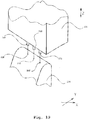
- Fig. 13
- eine Anordnung zum Messen teiltransparenter Schichten,
- Fig. 14
- eine Messanordnung zum Messen eines Höhenprofils,
- Fig. 15
- eine Messanordnung zum Messen eines Messobjektes in unterschiedlichen Stellungen,
- Fig. 16
- eine Anordnung zur Bestimmung der Lage eines Antastformelementes,
- Fig. 17
- eine Anordnung mit zwei miteinander verbundene Sensoren,
- Fig. 18
- eine Einspannanordnung für ein Messobjekt,
- Fig. 19
- einen Sensorrechen zur Messung mehrerer Messbahnen,
- Fig. 20
- eine Anordnung zur Messung eines Werkzeuges,
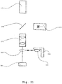
- Fig. 21
- eine Messanordnung mit Bildverarbeitungssensor und Laserabstandssensor,
- Fig. 22
- ein Prinzipbild zur Messung von durch Extrapolation ermittelten Messpunkten und
- Fig. 23
- eine Prinzipdarstellung einer Anordnung mit einem Röntgentomographiesensor.
- Fig. 1
- a schematic diagram of a coordinate measuring machine,
- Fig. 2
- a section of a coordinate measuring machine in a schematic representation,
- Fig. 3
- a schematic diagram of a coordinate measuring machine with image processing and laser distance sensor,
- 4:
- a schematic representation of a measuring method,
- Fig. 5:
- another schematic diagram of a measuring method,
- Fig. 6:
- a schematic representation of a contour tracing,
- Fig.7:
- Light intensity curves
- Fig. 8:
- a desired and an actual light intensity curve,
- Fig. 9:
- Target and actual comparison of contour data,
- 10a, 10b:
- Nominal and actual contours,
- 11, 12:
- a measuring object with tolerance zones,
- Fig. 13
- an arrangement for measuring partially transparent layers,
- Fig. 14
- a measuring arrangement for measuring a height profile,
- Fig. 15
- a measuring arrangement for measuring a measuring object in different positions,
- Fig. 16
- an arrangement for determining the position of a probing element,
- Fig. 17
- an arrangement with two interconnected sensors,
- Fig. 18
- a clamping arrangement for a measuring object,
- Fig. 19
- a sensor rake for measuring several measuring paths,
- Fig. 20
- an arrangement for measuring a tool,
- Fig. 21
- a measuring arrangement with image processing sensor and laser distance sensor,
- Fig. 22
- a schematic diagram for the measurement of measured by extrapolation measuring points and
- Fig. 23
- a schematic representation of an arrangement with an X-ray tomography sensor.
Die Erfindung bzw. Erfindungskomplexe werden nachstehend an bevorzugten Ausführungsbeispielen näher erläutert.The invention or complexes of the invention are explained in more detail below with reference to preferred embodiments.
Die entsprechenden Ausführungen erfolgen dabei vor dem Hintergrund, dass Kenntnisse der Koordinatenmesstechnik präsent sind. Ergänzend wird insoweit auf die Literaturstellen DE.Z.:
In
Das hinlänglich bekannte und noch einmal in der
Entlang dem Grundrahmen 12 ist ein Portal 18 in Y-Richtung verstellbar. Hierzu sind Säulen oder Ständer 20, 22 gleitend am Grundrahmen 12 abgestützt. Von den Säulen 20, 22 geht eine Traverse 24 aus, entlang der ein Schlitten verfahrbar ist, der seinerseits eine Pinole oder Säule 26 aufnimmt, die in Z-Richtung verstellbar ist. Von der Pinole 26 bzw. ggfs. einer mit der Pinole 26 verbundenen Wechselschnittstelle 28 geht ein Sensor 30 aus, der im Ausführungsbeispiel als taktiler Sensor ausgebildet ist, der dann, wenn die Pinole 26 einen Bildverarbeitungssensor enthält, taktil-optisch misst. Insoweit wird jedoch auf hinlänglich bekannte Techniken verwiesen, genauso wie in Bezug auf weitere zum Einsatz gelangende Sensoren wie Laserabstandssensor, Weißlichtinterferometer, Bildverarbeitungssensoren, Röntgensensorik oder chromatischer Fokussensor oder konfokal Scanning-Messkopf, ohne dass hierdurch eine Einschränkung der erfindungsgemäßen Lehre erfolgt. Der bzw. die Sensoren werden entsprechend der Messaufgabe ausgewählt und eingesetzt, um das Koordinatenmessgerät 10 für die jeweilige Messaufgabe optimal zu konfigurieren. Gleichzeitig werden Probleme gelöst, die bei üblichen Koordinatenmessgeräten auftreten.Along the
Um das Koordinatenmessgerät 10 mit dem geeigneten Sensor nutzen zu können, kann das Koordinatenmessgerät einen Sensorwechsler aufweisen, wie dies prinzipiell der
In
Bei Anwendung von Bildverarbeitungssensoren in Koordinatenmessgeräten ist es für den Anwender erforderlich, verschiedene Vergrößerungen einzustellen. Dem widerspricht die Forderung nach kostenoptimierten optischen Systemen sowie hohen Abbildungsgüten, die mit den sonst erforderlichen Zoom-Optiken nur schwer zu erreichen sind. Um diesen Forderungen zu genügen, ist vorgesehen, dass die Kamera des Bildverarbeitungssensors mit einer größeren Auflösung (Pixelanzahl) gewählt wird, als die Auflösung des verwendeten Monitors bzw. des für die Bilddarstellung verwendeten Monitorausschnitts. Im Weiteren kann die Kamera mit wahlfreiem Zugriff auf bestimmstimmte Ausschnitte des Gesamtbildes ausgestattet sein. Es ist dann möglich, dass im Live-Bild oder Beobachtungsbild des Koordinatenmessgerätes nur ein Ausschnitt des Gesamtbildes dargestellt wird, der auf das Format des jeweiligen Anzeigefensters bzw. Monitors vergrößert wird. Im Ergebnis hat der Anwender die Möglichkeit gezoomte Ausschnitte des Bildes entsprechend seinen Vorstellungen auszuwählen. Die Vergrößerung zwischen Messobjekt und Monitorbild kann durch Verändern des gewählten Ausschnittes des Kamerabildes durch die Software gesteuert werden oder auch das Live-Bild in gleicher Weise dargestellt werden. Die Vergrößerung zwischen Messobjekt und Monitorbild kann durch Verändern des gewählten Ausschnittes des Kamerabildes verändert werden. Dies kann gegebenenfalls durch einen Drehknopf, der in das Steuerungssystem des Koordinatenmessgerätes integriert ist, oder über einen Softwareregler bedient werden. Es ist fernerhin möglich, dass bei Einsatz einer hochauflösenden Kamera das Bild bzw. der Bildausschnitt nur in der geringeren Auflösung des Monitors angezeigt wird, im Hintergrund jedoch die volle Auflösung der Kamera zur digitalen Bildverarbeitung eingesetzt wird, um die Genauigkeit zu steigern. Die wirkliche optische Vergrößerung der Abbildungsoptik der Bildverarbeitung ist hierbei relativ gering (typisch 1-fach, höchstens jedoch 5-fach) und durch die Darstellung lediglich eines Ausschnittes des hoch auflösenden Kamerabildes auf dem geringer auflösenden Monitor wird die optische Wirkung einer höheren Vergrößerung erreicht.When using image processing sensors in coordinate measuring machines, it is necessary for the user to set different magnifications. This contradicts the demand for cost-optimized optical systems and high imaging qualities, which are difficult to achieve with the otherwise required zoom optics. To meet these requirements, it is provided that the camera of the image processing sensor is selected with a larger resolution (number of pixels) than the resolution of the monitor used or the monitor section used for the image display. In addition, the camera may have random access to certain voices Be part of the picture. It is then possible that in the live image or observation image of the coordinate measuring machine only a section of the overall image is displayed, which is enlarged to the format of the respective display window or monitor. As a result, the user has the option to select zoomed sections of the image according to his ideas. The magnification between the measurement object and the monitor image can be controlled by changing the selected section of the camera image by the software or the live image can be displayed in the same way. The magnification between the measurement object and the monitor image can be changed by changing the selected section of the camera image. This can optionally be operated by a rotary knob, which is integrated in the control system of the coordinate measuring machine, or via a software controller. It is also possible that when using a high-resolution camera, the image or the image is displayed only in the lower resolution of the monitor, in the background, however, the full resolution of the camera for digital image processing is used to increase the accuracy. The actual optical magnification of the imaging optics of the image processing here is relatively low (typically 1-fold, but at most 5-fold) and the representation of only a section of the high-resolution camera image on the lower-resolution monitor, the optical effect of higher magnification is achieved.
Das zuvor erläuterte Verfahren soll prinzipiell anhand der
Im Ausführungsbeispiel wird die Kamera 58 mit einer zusätzlichen Nachvergrößerungsoptik 62 ausgestattet, um den Abbildungsmaßstab zu definieren. Die im Strahlengang verwendeten optischen Teiler oder Spiegel, die in der
Ein Problem bei bekannten Koordinatenmessgeräten besteht darin, dass einmal erzeugte Programme zum Messen von Werkstücken nachträglich geändert bzw. nachträglich zusätzliche Merkmale aus den bereits gewonnenen Messergebnissen generiert werden sollen. Dies ist nach dem gegenwärtigen Stand der Technik nicht möglich, da die entsprechenden zugehörigen Technologiedaten nicht mehr vorhanden sind. Zur Lösung des Problems ist vorgesehen, dass die mit einem oder mehreren Sensoren des Koordinatenmessgerätes gemessenen Messpunkte bzw. Video-Bilder bzw. Röntgenbilder sowie deren zugehörige Position und andere Technologieparameter wie Einstellwert des verwendeten Beleuchtungssystems, Lichtintensität oder Vergrößerung des verwendeten Objektivs des Koordinatenmessgerätes während des Messablaufs aufgenommen abgespeichert und für eine spätere Auswertung so zur Verfügung gestellt werden. Analog zu dieser beschriebenen Vorgehensweise ist es ebenfalls möglich, dass mit dem Bildverarbeitungssensor mehrere Teilbilder eines Messobjekts einzeln gemessen und zu einem Gesamtbild des Gesamtmessobjekts oder zu einem Gesamtbild von Teilbereichen des gesamten Messobjekts zusammengefügt werden. Dieses Bild kann gespeichert werden und später auf einem separaten Arbeitsplatz ausgewertet werden. Hierzu werden ebenfalls die Kalibrierparameter des zur Bildaufnahme eingesetzten Koordinatenmessgerätes mitgespeichert und bei der Auswertung der Software erneut eingesetzt. Dies soll prinzipiell anhand der
Ein Messobjekt 68 soll mit einem Bildverarbeitungssensor gemessen werden. Mit den Bezugszeichen 70, 72, 76, 78 sind Bildausschnitte dargestellt, die bei verschiedenen Positionen im X-,Y-Koordinatensystem 80 des Koordinatenmessgerätes am Messobjekt 68 erfasst werden. Zusätzlich zu den eigentlichen X- und Y-Positionen werden die Bildinhalte der an den jeweiligen Positionen erfassten Objektausschnitte abgespeichert, dazu die jeweilig zugehörigen Bildverarbeitungsauswertefenster 82, 84, 86, 88 sowie die hierzu im Koordinatenmessgerät gespeicherten Parameter wie Vergrößerung des verwendeten Objektivs, Einstellwert des verwendeten Beleuchtungssystems. Nach Erfassung all dieser Werte kann auf einem Auswerterechner offline die eigentliche Messung der Bildinhalte und die Verknüpfung, z. B. die Messung eines Winkels 90 oder eines Abstandes 92, erfolgen.A measuring
Für den Fall, dass beim Einsatz eines Bildverarbeitungssensors das Sehfeld der Kamera nicht ausreicht, um das durch Wählen des gewünschten Auswertebereichs (Bildverarbeitungsfenster) definierte Areal des Messobjekts auf einmal zu erfassen, ist vorgesehen, dass automatisch ein Bild aus mehreren Teilen zusammengesetzt wird, das dem 30. September 2010-50575 BIf, when using an image processing sensor, the field of view of the camera is not sufficient to detect the area of the measurement object defined by selecting the desired evaluation area (image processing window) at once, it is provided that an image is automatically composed of several parts which are automatically combined September 30, 2010-50575 B
Anwender anschließend wie ein gemessenes Bild dargestellt und zur Auswertung zur Verfügung gestellt wird. Dies wird prinzipiell anhand der
Mittels der
- Suchen des Messobjekts im Messbereich des Koordinatenmessgerätes durch Fahren eines Sensors auf einem geradlinigen, spiralförmigen, mäanderförmigen, kreisbogenförmigen oder stochastischen oder anders gearteten Suchweg, bis die Existenz eines Messobjekts detektiert wird, und
- Starten eines Scanning der Außenkontur des Messobjekts (Konturverfolgung zur Erfassung der Geometrie und Lage der Außenkontur des Messobjekts).
- Searching the measuring object in the measuring range of the coordinate measuring machine by driving a sensor on a straight, spiral, meandering, circular arc or stochastic or other kind Such search path until the existence of a measuring object is detected, and
- Start a scanning of the outer contour of the measurement object (contour tracking to capture the geometry and position of the outer contour of the DUT).
Ferner können optional im Inneren der Außenkontur liegende Messpunkte auf dem Messobjekt durch Rastern mit einem Bildverarbeitungssensor und/oder Abtasten mit anderen Sensoren erfasst werden.Furthermore, optionally located in the interior of the outer contour measuring points on the measurement object can be detected by screening with an image processing sensor and / or scanning with other sensors.
So liegt auf dem Messtisch 12 ein Messobjekt 110. Ein für die Messung benutzter Bildverarbeitungssensor weist einen Auswertebereich 112 auf. Durch Bewegung auf einer z. B. spiralförmigen Bahn 114 wird die prinzipielle Lage des Messobjekts 110 auf dem Messtisch 12 durch Änderung des Bildinhalts erkannt. Beim Auftreffpunkt des Bildverarbeitungssensors mit der Objektkontur (Bereich 116) beginnt ein Außenkontur-Scanning des Messobjekts 110 bis zur vollständigen Erfassung der Außenkontur entlang der Bahn 118 (Konturverfolgung). Danach wird zur vollständigen Erfassung des Gesamtmessobjekts automatisch ein rasterförmiges Erfassen des inneren Bereichs des Messobjektes 110 in den zuvor definierten Außengrenzen 120 durchgeführt, so dass anschließend das Gesamtmessobjekt 118 zur Auswertung zur Verfügung steht.For example, a
Ein Problem beim Einsatz von Koordinatenmessgeräten mit Bildverarbeitungssensoren besteht darin, dass die verschiedenen Beleuchtungssysteme nicht lineare Kennlinien aufweisen. Dies führt u. a. dazu, dass verschiedene Messobjekte nicht richtig gemessen werden können oder Programme von einem auf das andere Gerät nicht ohne Weiteres übertragbar sind. Um dieses Problem zu lösen, wird erfindungsgemäß vorgeschlagen, dass die Kennlinien der Beleuchtungseinrichtungen des Bildverarbeitungssensorsystems des Koordinatenmessgerätes aufgenommen werden, d. h. es wird die Abhängigkeit der Beleuchtungsintensität vom Einstellbild der Bedieneroberfläche des Messgerätes durch Messen der Intensität zum zugehörigen Einstellwert mit der Bildverarbeitungssensorik erfasst. Entsprechende Messergebnisse werden als Kennlinie im Rechner des Messgerätes gespeichert. Auch besteht die Möglichkeit, die Messwerte in einer sogenannten Lichtbox zu speichern, die die Steuerung der Beleuchtungsintensität im Betrieb des Koordinatenmessgerätes vornimmt. Führt man diese Lichtkennlinienmessung an einem kalibrierten Referenzobjekt oder zumindest für mehrere Geräte an einem einheitlichen Kalibrierobjekt durch, wird die Möglichkeit eröffnet, die Geräte in ihrem Verhalten nach außen hin, d. h. in ihrem Verhalten bezüglich Abhängigkeit Einstellwert Licht - physikalischer Beleuchtungswert auszugleichen und somit die Programmübertragbarkeit von verschiedenen Geräten sicherzustellen.A problem with the use of coordinate measuring machines with image processing sensors is that the different lighting systems have non-linear characteristics. This leads u. a. In addition, different measurement objects can not be measured correctly or programs from one to the other device can not be easily transmitted. To solve this problem, the invention proposes that the characteristics of the illumination devices of the image processing sensor system of the coordinate measuring machine are recorded, d. H. the dependence of the illumination intensity on the adjustment image of the user interface of the measuring device is detected by measuring the intensity for the associated setting value with the image processing sensor system. Corresponding measurement results are stored as a characteristic curve in the computer of the measuring device. It is also possible to store the measured values in a so-called light box, which controls the illumination intensity during operation of the coordinate measuring machine. If one carries out this light characteristic measurement on a calibrated reference object or at least for several devices on a uniform calibration object, the possibility is opened up of the devices in their behavior towards the outside, ie. H. to compensate in their behavior with respect to the setting value light - physical illumination value and thus to ensure the program portability of different devices.
Um die Bedienung der Geräte zu erleichtern ist es sinnvoll, die Kennlinie so zu korrigieren, dass für den Bediener eine Linearität vorherrscht, d. h. , dass im Betrieb des Koordinatenmessgeräts die vorher eingemessene Kennlinie so für die Korrekturberechnung berücksichtigt wird, dass scheinbar eine lineare Kennlinie für den Bediener vorliegt. Sodann liegen die Einstellwerte und die Beleuchtungsintensität in linearer Beziehung zueinander. Der Anstieg dieser linearen Kennlinie kann sodann für mehrere Geräte durch einen einfachen Korrekturfaktor ausgeglichen werden.In order to facilitate the operation of the devices, it is useful to correct the characteristic so that the operator has a linearity, ie. H. in that, during operation of the coordinate measuring machine, the previously measured characteristic curve is taken into account for the correction calculation in such a way that a linear characteristic for the operator appears to be present. Then, the set values and the illumination intensity are linearly related to each other. The increase of this linear characteristic can then be compensated for several devices by a simple correction factor.
So ist in
Der physikalische Aufbau für den zuvor beschriebenen Vorgang ist der
Mit Koordinatenmessgeräten ist es möglich, Konturen auf Werkstückflächen zu scannen. Dies kann sowohl mit einem Sensor oder auch bei kombiniertem Betrieb mit mehreren Sensoren realisiert werden. Erfolgt eine Auswertung der Konturen durch Vergleich mit Sollkonturen aus z. B. CAD-Files, ist es erforderlich Soll- und Ist-Rechner intern übereinander zu legen, um einen grafischen Vergleich zu realisieren. Insbesondere bei flexiblen oder biegsamen Teilen ist dies durch einfaches Verschieben der Relativlage oder Verdrehen der Relativlage nicht möglich, da die Teile elastisch verformt sind. Durch Vorgehen nach der wie folgt beschriebenen Methode, wird dieses Problem gelöst. Es werden bei der Best-Einpassung zwischen Soll- und Ist-Kontur neben der Relativlageveränderung zwischen Soll- und Ist-Kontur an sich auch die Länge von Konturabschnitten entsprechend der Soll-Länge bei Beibehaltung der Krümmung oder alternativ die Konturkrümmung bei Beibehaltung der Konturlänge an der Ist-Kontur so verändert, dass eine optimale Überdeckung mit der Soll-Kontur erreicht wird. Sind Teile mit ausgezeichneten Geometriemerkmalen durch Elastizität oder Verformung schwierig zu überprüfen, kann dieser Vorgang dadurch unterstützt werden, dass die Einpassung zwischen Ist- und Soll-Kontur an einer Gruppe von Ist- und Soll-Konturen an einzeln ausgezeichneten Merkmalen, wie Kreuzungspunkten von Konturen oder Kreisstrukturen oder anderen wiederkehrenden Strukturen erfolgt und so einer Verzerrung der Ist-Kontur zur optimalen Überdeckung mit der Soll-Kontur generiert wird. In analoger Weise ist dies bei zylindrischen Teilen möglich, in dem die auf der Zylinderoberfläche gemessenen Konturen auf der Zylindermantelfläche partiell verdreht oder verschraubt werden, um eine optimale Überdeckung zwischen Soll- und Ist-Kontur herzustellen. Diese Verfahrensweise bietet sich insbesondere zur Messung von in der Medizin üblichen Stents an. Die oben beschriebene Methode ist auch in analog umgekehrter Vorgehensweise, d. h. Anpassung der Soll an die Ist-Geometrie möglich.With coordinate measuring machines, it is possible to scan contours on workpiece surfaces. This can be realized both with a sensor or even with combined operation with several sensors. Is an evaluation of the contours by comparison with target contours of z. As CAD files, it is necessary to set the target and actual computers internally on top of each other to realize a graphical comparison. In particular, in flexible or flexible parts, this is not possible by simply moving the relative position or rotation of the relative position, since the parts are elastically deformed. By following the procedure described below, this problem is solved. In addition to the relative position change between the nominal and actual contour, the length of contour sections corresponding to the nominal length while retaining the curvature or, alternatively, the contour curvature while maintaining the contour length at the Actual contour changed so that an optimal coverage is achieved with the target contour. If parts with excellent geometric features are difficult to check by elasticity or deformation, this process can be assisted by fitting the actual and target contours to a group of actual and target contours on individually distinguished features, such as contours or contours Circular structures or other recurring structures takes place and so a distortion of the actual contour for optimum coverage with the target contour is generated. In an analogous manner, this is possible in the case of cylindrical parts, in which the contours measured on the cylinder surface are partially twisted or screwed onto the cylinder jacket surface, in order to produce an optimum overlap between the desired and the actual contour. This procedure is particularly suitable for measuring standard stents in medicine. The method described above is also in analogous reverse procedure, d. H. Adaptation of the target to the actual geometry possible.
In
So ist in
Im vorliegenden Beispiel bedeutet dies, dass für das Element 1 automatisch zwei Toleranzzonen definiert werden (s.
Bei Einsatz einer Bildverarbeitung mit Autofokussensoren besteht häufig das Problem, dass teiltransparente Schichten in ihrer Höhenausdehnung gemessen werden müssen. Hierzu wird vorgeschlagen, dass mit dem Bildverarbeitungssensor im Autofokusbetrieb für mehrere Auswertebereiche gleichzeitig Autofokusmesspunkte an mehreren semi-transparenten Schichten generiert werden. Dies wird dadurch realisiert, dass der Bildverarbeitungssensor in Messrichtung verfahren und gleichzeitig mehrere Bilder aufgenommen werden. In den jeweils festgelegten Auswertebereichen werden entsprechend einem Kontrastkriterium die Fokusmesspunkte errechnet. Dies ergibt sich aus der
Mit Laserabstandssensoren in Koordinatenmessgeräten werden Konturen auf Werkstückoberflächen in Sensorrichtung gescannt, d. h. in einer Richtung, verschieden von der Sensormessrichtung, wird das Koordinatenmessgerät auf einer vorgegebenen Bahn bewegt. Es ist nun vorgesehen, dass die Lageregelung des Sensors bzw. der Lageregelkreis des Koordinatenmessgerätes in Abhängigkeit von der Auslenkungsanzeige des Laserabstandssensors so gesteuert wird, dass die Auslenkung des Laserabstandssensors konstant bleibt. Somit ist es möglich, Höhenlinien an einem Messobjekt zu scannen. Ein entsprechendes Höhenlinienscanning wird anhand der
Ein weiteres Problem beim Einsatz von Koordinatenmessgeräten besteht darin, dass die Messobjekte von verschiedenen Seiten gemessen werden müssen. Wird jedoch die Lage des Messobjekts im Koordinatenmessgerät verändert, geht der Bezug der Messpunkte untereinander verloren und eine gemeinsame Auswertung der Messpunkte ist nicht mehr möglich. Um diese Nachteile zu vermeiden, wird wie folgt verfahren:
- Messen der Position von einer oder mehreren, vorzugsweise drei Referenzmarken 184, 186 188 in Form von z. B.
Kugeln am Messobjekt 190 bzw. einerdas Messobjekt 190aufnehmenden Halterung 191 wie Rahmen, - Speichern der Position im Rechner des Koordinatenmessgerätes,
- Messen von beliebigen durch ein oder mehrere Sensoren 192
zugänglichen Punkten 194am Messobjekt 190, - Veränderung der Lage des
Messobjekts 190 im Messvolumen des Koordinatenmessgerätes durch Hand oder eine integrierte Drehachse oder Drehschwenkachse (Pfeil 196), - erneutes Messen der
Referenzmarken Position - interner Abgleich der jeweiligen Referenzmarken 184, 186, 188 bzw.
deren Positionen Messen weiterer Punkte 204am Messobjekt 190 mit einem oder mehreren Sensoren 192 des Koordinatenmessgerätes,- Wiederholung der oben genannten Vorgänge in beliebiger Anzahl,
- gemeinsame Auswertung aller, während der oben beschriebenen Messzyklen erfassten Messpunkte 194, 204 des
Messobjekts 190 in einem Koordinatensystem.
- Measuring the position of one or more, preferably three
reference marks object 190 or a measuringobject 190 receivingholder 191 as frame, - Storing the position in the computer of the coordinate measuring machine,
- Measuring any
points 194 on the measuringobject 190 accessible by one ormore sensors 192, - Change in the position of the measuring
object 190 in the measuring volume of the coordinate measuring machine by hand or an integrated rotary axis or pivot axis (arrow 196), - re-measuring the reference marks 184, 186, 188 and determining their changed
position - internal adjustment of the respective reference marks 184, 186, 188 or their
positions - Measuring
further points 204 on the measuringobject 190 with one ormore sensors 192 of the coordinate measuring machine, - Repetition of the above processes in any number,
- common evaluation of all, during the measurement cycles described above measuring
points object 190 in a coordinate system.
Koordinatenmessgeräte mit verschiedenen Sensoren weisen unter anderem auch wahlweise Sensoren mit einem opto-taktilen Taster auf. Dabei erfolgt die Bestimmung der Lage des Antastformelementes (Kugel oder Zylinder) durch einen Bildverarbeitungssensor. Das Problem besteht darin, diesen Sensor zur Position der Tastkugel zu justieren. Dies kann dadurch gelöst werden, dass auf der den Sensor tragenden Koordinatenachse zusätzlich eine Verstelleinheit angeordnet wird, die eine Relativverstellung zwischen dem Antastformelement (Tastkugel inklusive Taststift und Halter) in dem Bildverarbeitungssensor ermöglicht. Z. B. über ein Autofokusverfahren ist danach ein automatisches Scharfstellen des Antastformelementes in der Relation zum Bildverarbeitungssensor möglich.Coordinate measuring machines with various sensors also have, among other things, optionally sensors with an opto-tactile button. In this case, the determination of the position of the Antastformelementes (ball or cylinder) by an image processing sensor. The problem is to adjust this sensor to the position of the probe ball. This can be achieved by additionally arranging an adjusting unit on the coordinate axis bearing the sensor, which enables a relative adjustment between the sensing element (probe ball including stylus and holder) in the image processing sensor. For example, via an autofocus method, an automatic focusing of the detection element in relation to the image processing sensor is possible thereafter.
So ist in
Koordinatenmessgeräte sind im Allgemeinen am Einsatzort unterschiedlichen Einsatztemperaturen ausgesetzt. Sind mehrere Sensoren am Koordinatenmessgerät angebracht, führt dies dazu, dass thermisch bedingt sich die Positionen zwischen den verschiedenen Sensoren verändern. Dies führt zu Messfehlern. Zur Kompensation dieser wird die Temperatur der zur Befestigung der verschiedenen Sensoren benötigten mechanischen Baugruppen an einer oder mehreren Stellen gemessen und die Ausdehnung der entsprechenden mechanischen Komponenten bei der Berechnung der Messpunkte, die von den verschiedenen Sensoren erfasst werden, berücksichtigt.Coordinate measuring machines are generally exposed to different operating temperatures at the place of use. If several sensors are attached to the coordinate measuring machine, this will cause the positions between the different sensors to change thermally. This leads to measurement errors. To compensate for this, the temperature of the mechanical assemblies required for mounting the various sensors is measured at one or more locations and the expansion of the corresponding mechanical components is taken into account in the calculation of the measurement points detected by the various sensors.
So zeigt
Um ein Messobjekt während des Messens auf einem Koordinatenmessgerät von mehreren Seiten messen zu können ist es sinnvoll, dass das Messobjekt in eine Drehachse eingespannt und so in eine für die Messung mit den verschiedenen Sensoren optimale Position eingedreht werden kann. Ergänzend hierzu ist es möglich, das Messobjekt zusätzlich zur Drehachse selbst mit einer entsprechend angeordneten Gegenspitze aufzunehmen. Beim Einspannen eines Messobjekts zwischen Spitzen tritt jedoch das Problem auf, dass die Spannkraft der Gegenspitze zu Verformungen des Messobjekts führen kann. Um hierdurch bedingte Fehler auszuschließen, wird vorgeschlagen, dass das Messobjekt konstant verformt wird bzw. die Gegenspitze automatisch bis zur Erreichung einer vordefinierten Kraft an das Messobjekt heranpositioniert wird. Dabei kann die Gegenspitze gefedert gelagert sein, so dass über eine Auslenkung und einen entsprechenden Endschalter die entsprechend geforderte Kraft bestimmt werden kann.In order to be able to measure a measurement object on a coordinate measuring machine from several sides during the measurement, it makes sense that the measurement object can be clamped in an axis of rotation and thus be screwed into an optimum position for the measurement with the various sensors. In addition to this, it is possible to record the measurement object in addition to the rotation axis itself with a correspondingly arranged counter-tip. When clamping a measuring object between points, however, the problem arises that the clamping force of the opposite tip can lead to deformations of the test object. In order to exclude errors caused by this, it is proposed that the measured object is constantly deformed or the counter-tip is automatically positioned up to a predefined force on the measurement object. In this case, the counter-tip can be mounted sprung, so that via a deflection and a corresponding limit switch, the corresponding required force can be determined.
So zeigt
Ein weiteres Problem beim Einsatz von Koordinatenmessgeräten besteht darin, dass oft mehrere Konturen nahe beieinander gemessen werden sollen. Dies führt bei der geforderten Anzahl oft zu erheblich langen Messzeiten. Es ist vorgesehen, dass mehrere taktile Sensoren gleichartiger oder unterschiedlicher Bauweise dicht beieinander auf einer gemeinsamen mechanischen Achse des Koordinatenmessgerätes angeordnet werden.
Beim Messen mit einem Bildverarbeitungssensor an Außenkanten von Werkstücken wie Schneidwerkzeugen besteht das Problem, dass der Bildverarbeitungssensor auf die zu messende Außenkante permanent nachzufokussieren ist. Um diesen Nachteil zu vermeiden, ist vorgesehen, dass zusätzlich in dem Bildverarbeitungsstrahlengang ein Laserabstandssensor integriert wird. Der Lasersensor misst in der Nähe der zu messenden Außenkante den Abstand des Bildverarbeitungssensors zur Werkstückoberfläche und ist mit einem Lageregelkreis des Koordinatenmessgerätes so verbunden, dass eine automatische Nachführung erfolgt. Der Bildverarbeitungssensor ist somit permanent fokussiert. Dies wird anhand der
Bei einem erfindungsgemäßen Koordinatenmessgerät können Bildverarbeitungssensoren mit in den Strahlengang integrierten Lasersensoren zum Einsatz gelangen. Bei praktisch eingesetzten Systemen ist zu erwarten, dass die gewünschten optischen Eigenschaften für den integrierten Laserabstandssensor und den Bildverarbeitungssensor nicht bei den gleichen Einstellparametern (Arbeitsabstand / Vergrößerung) vorliegen. Durch eine zusätzlich einwechselbare Vorsatzoptik können Apertur und Arbeitsabstand des verwendeten Zoomoptiksystems alternativ für den Lasersensor und den Bildverarbeitungssensor optimiert werden.In a coordinate measuring machine according to the invention, image processing sensors with laser sensors integrated in the beam path can be used. In practically used systems, it is to be expected that the desired optical properties for the integrated laser distance sensor and the image processing sensor will not be present at the same setting parameters (working distance / magnification). By additionally exchangeable optical attachment optics and aperture of the zoom optical system used can alternatively be optimized for the laser sensor and the image processing sensor.
So sind in
Wird mit einem Autofokussensor die Oberflächenkontur von Werkstücken gemessen, werden die Messpunkte üblicherweise vom Bediener im Teach-in-Modus vorgegeben. Sollen unbekannte Konturen in diesem Verfahren gemessen werden, ist dies nur schwierig möglich. Um dies zu vermeiden, wird vorgeschlagen, dass mit einem Autofokussensor ein Scanningvorgang einer Materialoberfläche dadurch durchgeführt wird, dass aus den bereits gemessenen Fokuspunkten durch Extrapolation der voraussichtliche Ort des nächsten Messpunktes theoretisch errechnet und durch einen neuen Autofokuspunkt exakt nachgemessen wird. Wird dieser Vorgang mehrfach hintereinander wiederholt, ergibt sich ein vollautomatisches Scanning. Dabei kann sowohl die Anzahl der zu scannenden Punkte entlang einer Linie als auch ein zu scannender Bereich am Werkstück bzw. Messobjekt vom Bediener vorgegeben werden. Die Extrapolation des nächsten Messpunktes aus den beiden oder mehreren vorhergehenden Messpunkten kann durch eine lineare Extrapolation erfolgen.If the surface contour of workpieces is measured with an autofocus sensor, the measuring points are usually specified by the operator in the teach-in mode. If unknown contours are to be measured in this method, this is only possible with difficulty. In order to avoid this, it is proposed that a scanning process of a material surface is carried out with an autofocus sensor by theoretically calculating from the already measured focus points by extrapolation the prospective location of the next measuring point and measuring precisely by means of a new autofocus point. If this process is repeated several times in succession, this results in a fully automatic scanning. In this case, both the number of points to be scanned along a line and an area to be scanned on the workpiece or measured object can be specified by the operator. The extrapolation of the next measurement point from the two or more preceding measurement points can be done by a linear extrapolation.
So zeigt
Beim Einsatz von Bildverarbeitungssensoren oder Röntgentomographiesensoren tritt das Problem auf, dass je nach Eigenschaft des Messobjekts innerhalb eines Bildes sowohl Bereiche mit starken als auch mit schwachen Intensitäten vorliegen. Dies wird durch die unterschiedlichen Reflexions- bzw. Transmissionseigenschaften der Materialien verursacht. Im Ergebnis sind für die "dunklen" Bildbereiche nur geringe Signale vorhanden mit daraus folgendem schlechten Signalrauschverhältnis. Eine stärkere Beleuchtung bzw. Bestrahlung des Objekts würde jedoch zum Überstrahlen in den hellen Bereichen führen und schließt sich somit aus.When using image processing sensors or X-ray tomography sensors, the problem arises that, depending on the property of the measurement object within an image, there are regions with both strong and weak intensities. this will caused by the different reflection or transmission properties of the materials. As a result, only small signals are present for the "dark" image areas, resulting in a poor signal-to-noise ratio. However, a stronger illumination or irradiation of the object would lead to overshoot in the bright areas and thus excludes.
Um diese Nachteile zu vermeiden, ist vorgesehen, dass zu jedem im Bildausschnitt mehrere Bilder mit unterschiedlichen Beleuchtungsintensitäten aufgenommen werden. Anschließend werden diese Bilder des gleichen Objektbereiches in der Weise zu einem neuen Gesamtbild zusammengeführt, dass die Bildpunktamplituden auf die jeweilige Beleuchtungs- bzw. Bestrahlungsintensität, die verwendet wurde, normiert werden. Zur Gesamtbildzusammensetzung werden anschließend die Pixel auf dem jeweiligen Bild verwendet, die innerhalb des zugelassenen Dynamikbereiches liegen. Amplituden mit Überstrahlung werden aus dem jeweiligen Bild nicht berücksichtigt.In order to avoid these disadvantages, it is provided that several images with different illumination intensities are recorded for each person in the image section. Subsequently, these images of the same object area are merged to form a new overall image such that the pixel amplitudes are normalized to the respective illumination intensity that has been used. For overall image composition, the pixels on the respective image that are within the allowed dynamic range are then used. Overshoot amplitudes are not taken into account in the respective picture.
Entsprechend ist in
Claims (5)
- Method for measuring workpiece geometries using a coordinate measuring unit with movable traveling axes and with one or more sensors for detecting measurement points on the workpiece surfaces, a sensor being an image processing sensor which is associated with at least one lighting source or lighting system,
wherein
the light characteristics of lighting systems of the coordinate measuring unit, meaning the dependence of the lighting intensity on the set value at the operator interface of said measuring unit, are recorded by measurement on an object standardized or calibrated in its reflection behaviour and are standardized for several units, thereby ensuring the transferability of programs between said units. - Method according to claim 1,
wherein
recording of the characteristics of the lighting device is performed in that the dependence of the lighting intensity on the set value of the operator interface is obtained by measuring the intensity at the associated set value using the image processing sensors. - Method according to claim 1 or 2,
wherein
the characteristics are saved in the computer of the measuring unit or of a light box associated with said measuring unit that controls the lighting intensity during operation of the coordinate measuring unit. - Method according to at least one of the preceding claims,
wherein
the characteristics are corrected such that linearity predominates, i.e. set value and lighting intensity follow a linear correlation. - Method according to claim 4,
wherein
the rise in the characteristics is aligned by a correction factor for several units.
Applications Claiming Priority (3)
| Application Number | Priority Date | Filing Date | Title |
|---|---|---|---|
| DE102004061151 | 2004-12-16 | ||
| EP05819689A EP1846729A1 (en) | 2004-12-16 | 2005-12-16 | Coordinate measuring device and method for measuring with a coordinate measuring device |
| EP10165895.3A EP2224204B1 (en) | 2004-12-16 | 2005-12-16 | Method for measuring object geometries with a coordinate measuring device |
Related Parent Applications (5)
| Application Number | Title | Priority Date | Filing Date |
|---|---|---|---|
| EP05819689.0 Division | 2005-12-16 | ||
| EP10165895.3A Division-Into EP2224204B1 (en) | 2004-12-16 | 2005-12-16 | Method for measuring object geometries with a coordinate measuring device |
| EP10165895.3A Division EP2224204B1 (en) | 2004-12-16 | 2005-12-16 | Method for measuring object geometries with a coordinate measuring device |
| EP05819689A Division EP1846729A1 (en) | 2004-12-16 | 2005-12-16 | Coordinate measuring device and method for measuring with a coordinate measuring device |
| EP10165895.3 Division | 2010-06-14 |
Publications (3)
| Publication Number | Publication Date |
|---|---|
| EP2284486A2 EP2284486A2 (en) | 2011-02-16 |
| EP2284486A3 EP2284486A3 (en) | 2013-10-02 |
| EP2284486B1 true EP2284486B1 (en) | 2018-04-11 |
Family
ID=35985193
Family Applications (5)
| Application Number | Title | Priority Date | Filing Date |
|---|---|---|---|
| EP10185231.7A Active EP2284480B1 (en) | 2004-12-16 | 2005-12-16 | Method for measuring with a coordinate measuring device and coordinate measuring device |
| EP05819689A Ceased EP1846729A1 (en) | 2004-12-16 | 2005-12-16 | Coordinate measuring device and method for measuring with a coordinate measuring device |
| EP10185239.0A Not-in-force EP2284486B1 (en) | 2004-12-16 | 2005-12-16 | Method for measuring with a coordinate measuring device and coordinate measuring device |
| EP10185234.1A Not-in-force EP2284485B1 (en) | 2004-12-16 | 2005-12-16 | Method for measuring with a coordinate measuring device and coordinate measuring device |
| EP10165895.3A Active EP2224204B1 (en) | 2004-12-16 | 2005-12-16 | Method for measuring object geometries with a coordinate measuring device |
Family Applications Before (2)
| Application Number | Title | Priority Date | Filing Date |
|---|---|---|---|
| EP10185231.7A Active EP2284480B1 (en) | 2004-12-16 | 2005-12-16 | Method for measuring with a coordinate measuring device and coordinate measuring device |
| EP05819689A Ceased EP1846729A1 (en) | 2004-12-16 | 2005-12-16 | Coordinate measuring device and method for measuring with a coordinate measuring device |
Family Applications After (2)
| Application Number | Title | Priority Date | Filing Date |
|---|---|---|---|
| EP10185234.1A Not-in-force EP2284485B1 (en) | 2004-12-16 | 2005-12-16 | Method for measuring with a coordinate measuring device and coordinate measuring device |
| EP10165895.3A Active EP2224204B1 (en) | 2004-12-16 | 2005-12-16 | Method for measuring object geometries with a coordinate measuring device |
Country Status (4)
| Country | Link |
|---|---|
| US (1) | US20100014099A1 (en) |
| EP (5) | EP2284480B1 (en) |
| JP (2) | JP2008524565A (en) |
| WO (1) | WO2006063838A1 (en) |
Families Citing this family (46)
| Publication number | Priority date | Publication date | Assignee | Title |
|---|---|---|---|---|
| US20100014099A1 (en) * | 2004-12-16 | 2010-01-21 | Werth Messtechnik Gmbh | Coordinate measuring device and method for measuring with a coordinate measuring device |
| DE102007024197B4 (en) | 2007-05-24 | 2017-01-05 | Robert Bosch Gmbh | Device and method for measuring the shape of free-form surfaces |
| DE102007036795A1 (en) | 2007-08-03 | 2009-02-05 | Werth Messtechnik Gmbh | System to measure an object co-ordinates, by points or scanning, rejects reflections from surface faults |
| DE102007043741A1 (en) * | 2007-09-10 | 2009-03-12 | Eppendorf Ag | Optical sensor system on a device for the treatment of liquids |
| DE102007051054A1 (en) * | 2007-10-19 | 2009-04-30 | Carl Zeiss Industrielle Messtechnik Gmbh | Method for correcting the measured values of a coordinate measuring machine and coordinate measuring machine |
| KR101078651B1 (en) * | 2008-09-04 | 2011-11-01 | 삼성중공업 주식회사 | System and method for measuring a curved surface |
| DE102008037599A1 (en) | 2008-11-27 | 2010-06-02 | Werth Messtechnik Gmbh | Method for selection or scan measurement of object, involves configuring distance sensor for delivery of actual measurement data, where measurement spot of distance sensor is detected on object by image processing sensor |
| EP2194357A1 (en) * | 2008-12-03 | 2010-06-09 | Leica Geosystems AG | Optical sensor element for a measuring device and coupling element for this containing measuring device unit |
| US8378252B2 (en) * | 2009-05-29 | 2013-02-19 | Electro Scientific Industries, Inc. | Method and apparatus for hybrid resolution feedback of a motion stage |
| DE102010017604B4 (en) * | 2009-09-01 | 2016-03-10 | Werth Messtechnik Gmbh | Method for optically measuring structures of an object |
| JP5350169B2 (en) | 2009-10-13 | 2013-11-27 | 株式会社ミツトヨ | Offset amount calibration method and surface texture measuring machine |
| US8650939B2 (en) | 2009-10-13 | 2014-02-18 | Mitutoyo Corporation | Surface texture measuring machine and a surface texture measuring method |
| JP5350171B2 (en) | 2009-10-13 | 2013-11-27 | 株式会社ミツトヨ | Offset amount calibration method and surface texture measuring machine |
| WO2011064339A2 (en) * | 2009-11-26 | 2011-06-03 | Werth Messtechnik Gmbh | Method and arrangement for tactile-optical determination of the geometry of a measurement object |
| US8805035B2 (en) | 2010-05-03 | 2014-08-12 | Mim Software, Inc. | Systems and methods for contouring a set of medical images |
| CN103180691B (en) * | 2010-10-27 | 2016-08-10 | 株式会社尼康 | Shape measuring apparatus, process for measuring shape, the manufacture method of structure |
| JP5197712B2 (en) * | 2010-10-27 | 2013-05-15 | キヤノン株式会社 | Imaging device |
| DE102010054742A1 (en) | 2010-12-16 | 2012-06-21 | E. Zoller GmbH & Co. KG Einstell- und Messgeräte | Adjustment and / or meter device |
| JP5753409B2 (en) * | 2011-03-07 | 2015-07-22 | 株式会社トプコン | Panorama image creation method and three-dimensional laser scanner |
| DE102011050493A1 (en) * | 2011-05-19 | 2012-11-22 | Ludwig-Maximilians-Universität München | Device and method for detecting the deflection of elastic elements |
| CN103376058A (en) * | 2012-04-28 | 2013-10-30 | 鸿富锦精密工业(深圳)有限公司 | Temperature compensation system and method |
| JP2014006121A (en) * | 2012-06-22 | 2014-01-16 | Nagase Integrex Co Ltd | Distance sensor |
| US9188428B2 (en) | 2012-08-07 | 2015-11-17 | Carl Zeiss Industrielle Messtechnik Gmbh | Coordinate measuring machine with selectively active white light sensor |
| EP2847541B1 (en) * | 2012-08-07 | 2016-05-18 | Carl Zeiss Industrielle Messtechnik GmbH | Coordinate measuring device with a white light sensor |
| CN103673962B (en) * | 2012-09-12 | 2016-12-21 | 长江大学 | Contour line auto-measuring system and method |
| US9392158B2 (en) | 2012-10-04 | 2016-07-12 | Nvidia Corporation | Method and system for intelligent dynamic autofocus search |
| US9621780B2 (en) * | 2012-10-04 | 2017-04-11 | Nvidia Corporation | Method and system of curve fitting for common focus measures |
| DE102013105623A1 (en) | 2013-05-31 | 2014-12-04 | Werth Messtechnik Gmbh | Method for determining geometric features |
| DE102014108353A1 (en) | 2013-06-13 | 2014-12-18 | Werth Messtechnik Gmbh | Method and device for the determination of geometries on measured objects by means of a combined sensor system |
| EP2878920A1 (en) | 2013-11-28 | 2015-06-03 | Hexagon Technology Center GmbH | Calibration of a coordinate measuring machine using a calibration laser head at the tool centre point |
| CN104089655B (en) * | 2014-07-16 | 2016-05-25 | 宁波横河模具股份有限公司 | A kind of cooking machine comprehensive test device |
| DE202015103994U1 (en) | 2015-07-30 | 2015-10-06 | Werth Messtechnik Gmbh | Arrangement with at least one movable change station |
| DE202015104971U1 (en) | 2015-09-18 | 2016-12-20 | Werth Messtechnik Gmbh | Device, in particular coordinate measuring machine with at least one displaceable change station or withdrawal axis |
| JP6719815B2 (en) * | 2016-03-16 | 2020-07-08 | 株式会社ミツトヨ | Control method of surface texture measuring machine |
| DE102017107343A1 (en) | 2016-06-21 | 2017-12-21 | Werth Messtechnik Gmbh | Method and apparatus for operating an optical distance sensor |
| CN106403845B (en) * | 2016-09-14 | 2017-10-03 | 杭州思看科技有限公司 | Three-dimension sensor system and three-dimensional data acquisition methods |
| CN106767615B (en) * | 2016-12-15 | 2019-05-21 | 北京泰诚信测控技术股份有限公司 | A kind of transmission bearing gasket detection device |
| DE102017203084B4 (en) | 2017-02-24 | 2020-10-29 | Carl Zeiss Industrielle Messtechnik Gmbh | Method for determining correction data for correcting temperature-dependent measurement data of an optical sensor |
| EP3450909A1 (en) | 2017-09-05 | 2019-03-06 | Renishaw PLC | Non-contact optical tool setting apparatus and method |
| TWI645157B (en) * | 2017-11-24 | 2018-12-21 | 國立高雄應用科技大學 | Optical measurement system and method for workpiece contour |
| DE102018111473B4 (en) * | 2018-05-14 | 2022-01-13 | Trumpf Laser- Und Systemtechnik Gmbh | Method and detection device for determining the contour accuracy of a kinematic assembly |
| CN109556519A (en) * | 2018-11-07 | 2019-04-02 | 西北工业大学 | A kind of extension deforming high precision measuring device and method |
| JP7219056B2 (en) * | 2018-11-09 | 2023-02-07 | 株式会社キーエンス | Displacement measuring device |
| CN109648400B (en) * | 2019-01-25 | 2020-07-10 | 上海交通大学 | Valve core working edge burr form reconstruction method based on white light confocal in-situ measurement |
| DE102022118320A1 (en) | 2021-07-23 | 2023-01-26 | Werth Messtechnik Gmbh | Device comprising a coordinate measuring machine and method for operating |
| DE102023117023A1 (en) | 2022-06-30 | 2024-01-04 | Werth Messtechnik Gmbh | Method for operating a coordinate measuring machine and device for carrying it out |
Family Cites Families (43)
| Publication number | Priority date | Publication date | Assignee | Title |
|---|---|---|---|---|
| JPS58122414A (en) * | 1982-01-18 | 1983-07-21 | Toshiba Corp | Measuring method of micro-dimension |
| IT1198660B (en) * | 1983-08-02 | 1988-12-21 | Ottica Ist Naz | MULTIFOCAL OPTICAL PROFILOMETER FOR DISPERSION |
| JPS6117011A (en) * | 1984-07-03 | 1986-01-25 | Komatsu Ltd | Measuring method of size in double housing machine tool |
| DE3634689A1 (en) * | 1986-10-11 | 1988-04-14 | Zeiss Carl Fa | ARRANGEMENT FOR THE SIMULTANEOUS CONNECTION OF SEVERAL PROBE HEADS OF THE SWITCHING TYPE TO THE ARM OF A COORDINATE MEASURING DEVICE |
| DE3635840A1 (en) * | 1986-10-22 | 1988-05-05 | Thomson Brandt Gmbh | SCANNING SCANNING SYSTEM |
| JP2791020B2 (en) * | 1987-09-21 | 1998-08-27 | 株式会社日立製作所 | Signal-to-noise ratio improvement method and scanning electron microscope |
| DE3806686A1 (en) * | 1988-03-02 | 1989-09-14 | Wegu Messtechnik | MULTICOORDINATE MEASURING AND TESTING DEVICE |
| DE8813875U1 (en) * | 1988-11-05 | 1988-12-22 | Fa. Carl Zeiss, 7920 Heidenheim, De | |
| DE3841488A1 (en) * | 1988-12-09 | 1990-06-13 | Zeiss Carl Fa | COORDINATE MEASURING DEVICE WITH ONE OR SEVERAL ALUMINUM GUIDE ELEMENTS |
| GB2227563B (en) * | 1989-01-28 | 1992-07-01 | Ferranti Int Signal | Error determination for multi-axis apparatus due to thermal distortion |
| DE4026942A1 (en) * | 1990-08-25 | 1992-02-27 | Zeiss Carl Fa | METHOD FOR CONTACTLESS MEASUREMENT OF OBJECT SURFACES |
| DE4134481C2 (en) * | 1991-10-18 | 1998-04-09 | Zeiss Carl Fa | Surgical microscope for computer-aided, stereotactic microsurgery |
| GB9126269D0 (en) * | 1991-12-11 | 1992-02-12 | Renishaw Metrology Ltd | Temperature sensor for coordinate positioning apparatus |
| JPH05223526A (en) * | 1992-02-10 | 1993-08-31 | Hitachi Ltd | Plate thickness measuring apparatus |
| DE4327250C5 (en) * | 1992-09-25 | 2008-11-20 | Carl Zeiss Industrielle Messtechnik Gmbh | Method for measuring coordinates on workpieces |
| JPH0727572A (en) * | 1993-07-08 | 1995-01-27 | Mitsutoyo Corp | Length measuring device |
| JPH07229733A (en) * | 1994-02-15 | 1995-08-29 | Mitsubishi Heavy Ind Ltd | Device for measuring roll profile |
| JP3544589B2 (en) * | 1995-09-05 | 2004-07-21 | 株式会社ミツトヨ | Length measuring device |
| JP3335857B2 (en) * | 1996-12-12 | 2002-10-21 | 株式会社東芝 | Heat-resistant measuring instrument |
| GB9705105D0 (en) * | 1997-03-12 | 1997-04-30 | Brown & Sharpe Limited | Optical surface measurement apparatus and methods |
| DE19747027A1 (en) * | 1997-04-21 | 1998-10-22 | Wegu Messtechnik | Multiple sensor scan device e.g. for coordinate measuring device |
| WO1998057121A1 (en) | 1997-06-12 | 1998-12-17 | Werth Messtechnik Gmbh | Coordinate measuring instrument with feeler and optic sensor for measuring the position of the feeler |
| DE19811202C2 (en) * | 1998-03-09 | 2002-01-17 | Gf Mestechnik Gmbh | Confocal scanning microscope |
| JP2000329531A (en) * | 1999-03-17 | 2000-11-30 | Minolta Co Ltd | Apparatus and method for measurement of three- dimensional shape |
| JP2001082950A (en) * | 1999-09-13 | 2001-03-30 | Toshiba Corp | Thickness gauge |
| JP2001169155A (en) * | 1999-12-14 | 2001-06-22 | Minolta Co Ltd | Digital camera and recording medium |
| EP1128156A1 (en) * | 2000-02-10 | 2001-08-29 | General Electric Company | Method and apparatus for automatically compensating for measurement error |
| EP1299691B1 (en) * | 2000-07-13 | 2004-12-08 | Werth Messtechnik GmbH | Method for carrying out the non-contact measurement of geometries of objects |
| WO2002025206A1 (en) * | 2000-09-20 | 2002-03-28 | Werth Messtechnik Gmbh | Assembly and method for the optical-tactile measurement of a structure |
| JP2002207163A (en) * | 2001-01-05 | 2002-07-26 | Fuji Photo Optical Co Ltd | Range finder of television lens |
| DE10215135A1 (en) * | 2001-04-18 | 2002-10-24 | Zeiss Carl | Automatic regulation of focus and lighting and optical sensing of edge position for precision optical measurement involves determining weighted sum of individual auxiliary parameters |
| JP3726699B2 (en) * | 2001-04-20 | 2005-12-14 | 日本ビクター株式会社 | Optical imaging device, optical distance measuring device |
| DE10211760A1 (en) * | 2002-03-14 | 2003-10-02 | Werth Messtechnik Gmbh | Arrangement and method for measuring geometries or structures of essentially two-dimensional objects by means of image processing sensors |
| DE10212004A1 (en) * | 2002-03-18 | 2003-10-02 | Zoller Gmbh & Co Kg | Method and device for detecting at least a section of a workpiece or a tool |
| JP4030002B2 (en) * | 2002-03-18 | 2008-01-09 | フジノン株式会社 | Visible infrared imaging camera |
| JP2004023632A (en) * | 2002-06-19 | 2004-01-22 | Fuji Photo Film Co Ltd | Digital camera |
| EP1380263B1 (en) * | 2002-07-12 | 2007-08-29 | MYCRONA Gesellschaft für innovative Messtechnik mbH | Process and device for measuring the actual position of the structure of an object to be examined |
| DE10251412B4 (en) * | 2002-11-01 | 2016-10-06 | Werth Messtechnik Gmbh | Arrangement for measuring the geometry and / or structure of an object |
| US20060007449A1 (en) * | 2002-12-13 | 2006-01-12 | Ralf Christoph | Method for measuring a contour of a workpiece by scanning |
| DE10260256B9 (en) * | 2002-12-20 | 2007-03-01 | Carl Zeiss | Interferometer system and measuring / machining tool |
| DE10313038B4 (en) * | 2003-03-24 | 2005-02-17 | Klingelnberg Gmbh | Device for detecting the position of a probe element in a multi-coordinate measuring device |
| DE10356412A1 (en) * | 2003-11-24 | 2005-06-23 | Universität Stuttgart | Confocal arrangement for e.g. three-dimensional tooth shape measurement, has telecentric aperture arranged in internal focal plane of objective lenses to limit numerical aperture of lens, facing object, around specific value |
| US20100014099A1 (en) * | 2004-12-16 | 2010-01-21 | Werth Messtechnik Gmbh | Coordinate measuring device and method for measuring with a coordinate measuring device |
-
2005
- 2005-12-16 US US11/721,854 patent/US20100014099A1/en not_active Abandoned
- 2005-12-16 EP EP10185231.7A patent/EP2284480B1/en active Active
- 2005-12-16 EP EP05819689A patent/EP1846729A1/en not_active Ceased
- 2005-12-16 EP EP10185239.0A patent/EP2284486B1/en not_active Not-in-force
- 2005-12-16 WO PCT/EP2005/013526 patent/WO2006063838A1/en active Application Filing
- 2005-12-16 EP EP10185234.1A patent/EP2284485B1/en not_active Not-in-force
- 2005-12-16 JP JP2007545955A patent/JP2008524565A/en active Pending
- 2005-12-16 EP EP10165895.3A patent/EP2224204B1/en active Active
-
2012
- 2012-03-13 JP JP2012055740A patent/JP2012137498A/en active Pending
Non-Patent Citations (1)
| Title |
|---|
| None * |
Also Published As
| Publication number | Publication date |
|---|---|
| JP2008524565A (en) | 2008-07-10 |
| EP2284486A3 (en) | 2013-10-02 |
| WO2006063838A1 (en) | 2006-06-22 |
| EP2284485B1 (en) | 2015-09-16 |
| EP2284480A3 (en) | 2013-05-15 |
| EP2224204B1 (en) | 2021-05-26 |
| EP2284480B1 (en) | 2014-08-27 |
| EP2224204A2 (en) | 2010-09-01 |
| EP2224204A3 (en) | 2013-05-15 |
| US20100014099A1 (en) | 2010-01-21 |
| EP2284485A2 (en) | 2011-02-16 |
| EP2284486A2 (en) | 2011-02-16 |
| EP1846729A1 (en) | 2007-10-24 |
| EP2284480A2 (en) | 2011-02-16 |
| EP2284485A3 (en) | 2013-05-15 |
| JP2012137498A (en) | 2012-07-19 |
Similar Documents
| Publication | Publication Date | Title |
|---|---|---|
| EP2284486B1 (en) | Method for measuring with a coordinate measuring device and coordinate measuring device | |
| EP2793069B1 (en) | Digital microscope and method for optimising the work process in a digital microscope | |
| DE102016202928B4 (en) | Improved autofocus method for a coordinate measuring machine | |
| DE102007018416A1 (en) | Method and device for machine cutting a plate-shaped workpiece | |
| WO2015082683A2 (en) | Device and method for measuring workpieces | |
| DE102012216908B4 (en) | Method using image correlation to determine position measurements in a machine vision system | |
| EP3044536B1 (en) | Method and apparatus for measuring internal threads of a workpiece using an optical sensor | |
| DE10211070A1 (en) | Device for measuring a measurement object | |
| DE102015102111A1 (en) | Multi-head laser system with sensor unit | |
| DE102017129221A1 (en) | Method and device for determining geometric features on workpieces | |
| EP1640688A1 (en) | Method and Apparatus for Measuring the Surface on an Object in three Dimensions | |
| WO2015176888A1 (en) | Improved auto focus method for a coordinate measuring device | |
| EP3303990B1 (en) | Lighting control when using optical measuring devices | |
| DE102018218095B4 (en) | Procedure for edge determination of a measurement object in optical metrology and coordinate measuring machine | |
| DE102013211286A1 (en) | Method for measuring a workpiece with an optical sensor | |
| DE102011008513A1 (en) | Adjustment or measurement device for measuring or adjusting tool, has tool detection unit for contactless measurement of tool, where tool detection unit has illumination devices | |
| EP2191229B1 (en) | Method for determining an edge of an object to be optically measured, and coordinate measuring device | |
| DE19629616A1 (en) | Appliance for setting up, measuring and checking processing machine tools | |
| DE102015117276B4 (en) | Method and device for measuring a test object with improved measuring accuracy | |
| WO2014094828A1 (en) | Zoom lens having setting error correction | |
| DE102019111557B4 (en) | Sensor and method for determining the geometric properties of a measurement object | |
| EP3978866A1 (en) | Method for determining the geometry of an object and optical measuring device | |
| DE102020105768A1 (en) | Coordinate measuring machine and method for operating the same | |
| DE102014119436B4 (en) | Coordinate measuring machine and method for determining geometric properties of a measurement object using a light field camera | |
| DE10203797C1 (en) | Three-dimensional interferometric measuring method allows evaluation of depth information for interesting area of camera image selected via defined criteria |
Legal Events
| Date | Code | Title | Description |
|---|---|---|---|
| PUAI | Public reference made under article 153(3) epc to a published international application that has entered the european phase |
Free format text: ORIGINAL CODE: 0009012 |
|
| AC | Divisional application: reference to earlier application |
Ref document number: 1846729 Country of ref document: EP Kind code of ref document: P Ref document number: 2224204 Country of ref document: EP Kind code of ref document: P |
|
| AK | Designated contracting states |
Kind code of ref document: A2 Designated state(s): AT BE BG CH CY CZ DE DK EE ES FI FR GB GR HU IE IS IT LI LT LU LV MC NL PL PT RO SE SI SK TR |
|
| RIC1 | Information provided on ipc code assigned before grant |
Ipc: G01B 21/04 20060101AFI20130410BHEP |
|
| PUAL | Search report despatched |
Free format text: ORIGINAL CODE: 0009013 |
|
| AK | Designated contracting states |
Kind code of ref document: A3 Designated state(s): AT BE BG CH CY CZ DE DK EE ES FI FR GB GR HU IE IS IT LI LT LU LV MC NL PL PT RO SE SI SK TR |
|
| RIC1 | Information provided on ipc code assigned before grant |
Ipc: G01B 21/04 20060101AFI20130823BHEP |
|
| 17P | Request for examination filed |
Effective date: 20140328 |
|
| RBV | Designated contracting states (corrected) |
Designated state(s): AT BE BG CH CY CZ DE DK EE ES FI FR GB GR HU IE IS IT LI LT LU LV MC NL PL PT RO SE SI SK TR |
|
| GRAP | Despatch of communication of intention to grant a patent |
Free format text: ORIGINAL CODE: EPIDOSNIGR1 |
|
| STAA | Information on the status of an ep patent application or granted ep patent |
Free format text: STATUS: GRANT OF PATENT IS INTENDED |
|
| INTG | Intention to grant announced |
Effective date: 20170830 |
|
| GRAS | Grant fee paid |
Free format text: ORIGINAL CODE: EPIDOSNIGR3 |
|
| GRAJ | Information related to disapproval of communication of intention to grant by the applicant or resumption of examination proceedings by the epo deleted |
Free format text: ORIGINAL CODE: EPIDOSDIGR1 |
|
| GRAL | Information related to payment of fee for publishing/printing deleted |
Free format text: ORIGINAL CODE: EPIDOSDIGR3 |
|
| STAA | Information on the status of an ep patent application or granted ep patent |
Free format text: STATUS: REQUEST FOR EXAMINATION WAS MADE |
|
| INTC | Intention to grant announced (deleted) | ||
| GRAP | Despatch of communication of intention to grant a patent |
Free format text: ORIGINAL CODE: EPIDOSNIGR1 |
|
| STAA | Information on the status of an ep patent application or granted ep patent |
Free format text: STATUS: GRANT OF PATENT IS INTENDED |
|
| INTG | Intention to grant announced |
Effective date: 20180205 |
|
| GRAA | (expected) grant |
Free format text: ORIGINAL CODE: 0009210 |
|
| STAA | Information on the status of an ep patent application or granted ep patent |
Free format text: STATUS: THE PATENT HAS BEEN GRANTED |
|
| AC | Divisional application: reference to earlier application |
Ref document number: 1846729 Country of ref document: EP Kind code of ref document: P Ref document number: 2224204 Country of ref document: EP Kind code of ref document: P |
|
| AK | Designated contracting states |
Kind code of ref document: B1 Designated state(s): AT BE BG CH CY CZ DE DK EE ES FI FR GB GR HU IE IS IT LI LT LU LV MC NL PL PT RO SE SI SK TR |
|
| REG | Reference to a national code |
Ref country code: GB Ref legal event code: FG4D Free format text: NOT ENGLISH |
|
| REG | Reference to a national code |
Ref country code: CH Ref legal event code: EP |
|
| REG | Reference to a national code |
Ref country code: AT Ref legal event code: REF Ref document number: 988518 Country of ref document: AT Kind code of ref document: T Effective date: 20180415 |
|
| REG | Reference to a national code |
Ref country code: IE Ref legal event code: FG4D Free format text: LANGUAGE OF EP DOCUMENT: GERMAN |
|
| REG | Reference to a national code |
Ref country code: DE Ref legal event code: R096 Ref document number: 502005015814 Country of ref document: DE |
|
| REG | Reference to a national code |
Ref country code: CH Ref legal event code: NV Representative=s name: LUCHS AND PARTNER PATENTANWAELTE, CH |
|
| REG | Reference to a national code |
Ref country code: NL Ref legal event code: MP Effective date: 20180411 |
|
| REG | Reference to a national code |
Ref country code: LT Ref legal event code: MG4D |
|
| PG25 | Lapsed in a contracting state [announced via postgrant information from national office to epo] |
Ref country code: NL Free format text: LAPSE BECAUSE OF FAILURE TO SUBMIT A TRANSLATION OF THE DESCRIPTION OR TO PAY THE FEE WITHIN THE PRESCRIBED TIME-LIMIT Effective date: 20180411 |
|
| PG25 | Lapsed in a contracting state [announced via postgrant information from national office to epo] |
Ref country code: LT Free format text: LAPSE BECAUSE OF FAILURE TO SUBMIT A TRANSLATION OF THE DESCRIPTION OR TO PAY THE FEE WITHIN THE PRESCRIBED TIME-LIMIT Effective date: 20180411 Ref country code: FI Free format text: LAPSE BECAUSE OF FAILURE TO SUBMIT A TRANSLATION OF THE DESCRIPTION OR TO PAY THE FEE WITHIN THE PRESCRIBED TIME-LIMIT Effective date: 20180411 Ref country code: SE Free format text: LAPSE BECAUSE OF FAILURE TO SUBMIT A TRANSLATION OF THE DESCRIPTION OR TO PAY THE FEE WITHIN THE PRESCRIBED TIME-LIMIT Effective date: 20180411 Ref country code: PL Free format text: LAPSE BECAUSE OF FAILURE TO SUBMIT A TRANSLATION OF THE DESCRIPTION OR TO PAY THE FEE WITHIN THE PRESCRIBED TIME-LIMIT Effective date: 20180411 Ref country code: ES Free format text: LAPSE BECAUSE OF FAILURE TO SUBMIT A TRANSLATION OF THE DESCRIPTION OR TO PAY THE FEE WITHIN THE PRESCRIBED TIME-LIMIT Effective date: 20180411 Ref country code: BG Free format text: LAPSE BECAUSE OF FAILURE TO SUBMIT A TRANSLATION OF THE DESCRIPTION OR TO PAY THE FEE WITHIN THE PRESCRIBED TIME-LIMIT Effective date: 20180711 |
|
| PG25 | Lapsed in a contracting state [announced via postgrant information from national office to epo] |
Ref country code: LV Free format text: LAPSE BECAUSE OF FAILURE TO SUBMIT A TRANSLATION OF THE DESCRIPTION OR TO PAY THE FEE WITHIN THE PRESCRIBED TIME-LIMIT Effective date: 20180411 Ref country code: GR Free format text: LAPSE BECAUSE OF FAILURE TO SUBMIT A TRANSLATION OF THE DESCRIPTION OR TO PAY THE FEE WITHIN THE PRESCRIBED TIME-LIMIT Effective date: 20180712 |
|
| PG25 | Lapsed in a contracting state [announced via postgrant information from national office to epo] |
Ref country code: PT Free format text: LAPSE BECAUSE OF FAILURE TO SUBMIT A TRANSLATION OF THE DESCRIPTION OR TO PAY THE FEE WITHIN THE PRESCRIBED TIME-LIMIT Effective date: 20180813 |
|
| REG | Reference to a national code |
Ref country code: DE Ref legal event code: R097 Ref document number: 502005015814 Country of ref document: DE |
|
| PG25 | Lapsed in a contracting state [announced via postgrant information from national office to epo] |
Ref country code: DK Free format text: LAPSE BECAUSE OF FAILURE TO SUBMIT A TRANSLATION OF THE DESCRIPTION OR TO PAY THE FEE WITHIN THE PRESCRIBED TIME-LIMIT Effective date: 20180411 Ref country code: EE Free format text: LAPSE BECAUSE OF FAILURE TO SUBMIT A TRANSLATION OF THE DESCRIPTION OR TO PAY THE FEE WITHIN THE PRESCRIBED TIME-LIMIT Effective date: 20180411 Ref country code: RO Free format text: LAPSE BECAUSE OF FAILURE TO SUBMIT A TRANSLATION OF THE DESCRIPTION OR TO PAY THE FEE WITHIN THE PRESCRIBED TIME-LIMIT Effective date: 20180411 Ref country code: SK Free format text: LAPSE BECAUSE OF FAILURE TO SUBMIT A TRANSLATION OF THE DESCRIPTION OR TO PAY THE FEE WITHIN THE PRESCRIBED TIME-LIMIT Effective date: 20180411 Ref country code: CZ Free format text: LAPSE BECAUSE OF FAILURE TO SUBMIT A TRANSLATION OF THE DESCRIPTION OR TO PAY THE FEE WITHIN THE PRESCRIBED TIME-LIMIT Effective date: 20180411 |
|
| PLBE | No opposition filed within time limit |
Free format text: ORIGINAL CODE: 0009261 |
|
| STAA | Information on the status of an ep patent application or granted ep patent |
Free format text: STATUS: NO OPPOSITION FILED WITHIN TIME LIMIT |
|
| PG25 | Lapsed in a contracting state [announced via postgrant information from national office to epo] |
Ref country code: IT Free format text: LAPSE BECAUSE OF FAILURE TO SUBMIT A TRANSLATION OF THE DESCRIPTION OR TO PAY THE FEE WITHIN THE PRESCRIBED TIME-LIMIT Effective date: 20180411 |
|
| 26N | No opposition filed |
Effective date: 20190114 |
|
| PG25 | Lapsed in a contracting state [announced via postgrant information from national office to epo] |
Ref country code: SI Free format text: LAPSE BECAUSE OF FAILURE TO SUBMIT A TRANSLATION OF THE DESCRIPTION OR TO PAY THE FEE WITHIN THE PRESCRIBED TIME-LIMIT Effective date: 20180411 |
|
| GBPC | Gb: european patent ceased through non-payment of renewal fee |
Effective date: 20181216 |
|
| PG25 | Lapsed in a contracting state [announced via postgrant information from national office to epo] |
Ref country code: MC Free format text: LAPSE BECAUSE OF FAILURE TO SUBMIT A TRANSLATION OF THE DESCRIPTION OR TO PAY THE FEE WITHIN THE PRESCRIBED TIME-LIMIT Effective date: 20180411 Ref country code: LU Free format text: LAPSE BECAUSE OF NON-PAYMENT OF DUE FEES Effective date: 20181216 |
|
| REG | Reference to a national code |
Ref country code: IE Ref legal event code: MM4A |
|
| REG | Reference to a national code |
Ref country code: BE Ref legal event code: MM Effective date: 20181231 |
|
| PG25 | Lapsed in a contracting state [announced via postgrant information from national office to epo] |
Ref country code: IE Free format text: LAPSE BECAUSE OF NON-PAYMENT OF DUE FEES Effective date: 20181216 |
|
| PG25 | Lapsed in a contracting state [announced via postgrant information from national office to epo] |
Ref country code: BE Free format text: LAPSE BECAUSE OF NON-PAYMENT OF DUE FEES Effective date: 20181231 |
|
| PG25 | Lapsed in a contracting state [announced via postgrant information from national office to epo] |
Ref country code: GB Free format text: LAPSE BECAUSE OF NON-PAYMENT OF DUE FEES Effective date: 20181216 |
|
| PGFP | Annual fee paid to national office [announced via postgrant information from national office to epo] |
Ref country code: FR Payment date: 20191220 Year of fee payment: 15 |
|
| PG25 | Lapsed in a contracting state [announced via postgrant information from national office to epo] |
Ref country code: TR Free format text: LAPSE BECAUSE OF FAILURE TO SUBMIT A TRANSLATION OF THE DESCRIPTION OR TO PAY THE FEE WITHIN THE PRESCRIBED TIME-LIMIT Effective date: 20180411 |
|
| PGFP | Annual fee paid to national office [announced via postgrant information from national office to epo] |
Ref country code: AT Payment date: 20191220 Year of fee payment: 15 Ref country code: CH Payment date: 20191219 Year of fee payment: 15 |
|
| PG25 | Lapsed in a contracting state [announced via postgrant information from national office to epo] |
Ref country code: HU Free format text: LAPSE BECAUSE OF FAILURE TO SUBMIT A TRANSLATION OF THE DESCRIPTION OR TO PAY THE FEE WITHIN THE PRESCRIBED TIME-LIMIT; INVALID AB INITIO Effective date: 20051216 Ref country code: CY Free format text: LAPSE BECAUSE OF FAILURE TO SUBMIT A TRANSLATION OF THE DESCRIPTION OR TO PAY THE FEE WITHIN THE PRESCRIBED TIME-LIMIT Effective date: 20180411 |
|
| PG25 | Lapsed in a contracting state [announced via postgrant information from national office to epo] |
Ref country code: IS Free format text: LAPSE BECAUSE OF FAILURE TO SUBMIT A TRANSLATION OF THE DESCRIPTION OR TO PAY THE FEE WITHIN THE PRESCRIBED TIME-LIMIT Effective date: 20180811 |
|
| REG | Reference to a national code |
Ref country code: CH Ref legal event code: PL |
|
| REG | Reference to a national code |
Ref country code: AT Ref legal event code: MM01 Ref document number: 988518 Country of ref document: AT Kind code of ref document: T Effective date: 20201216 |
|
| PG25 | Lapsed in a contracting state [announced via postgrant information from national office to epo] |
Ref country code: FR Free format text: LAPSE BECAUSE OF NON-PAYMENT OF DUE FEES Effective date: 20201231 Ref country code: AT Free format text: LAPSE BECAUSE OF NON-PAYMENT OF DUE FEES Effective date: 20201216 |
|
| PG25 | Lapsed in a contracting state [announced via postgrant information from national office to epo] |
Ref country code: LI Free format text: LAPSE BECAUSE OF NON-PAYMENT OF DUE FEES Effective date: 20201231 Ref country code: CH Free format text: LAPSE BECAUSE OF NON-PAYMENT OF DUE FEES Effective date: 20201231 |
|
| PGFP | Annual fee paid to national office [announced via postgrant information from national office to epo] |
Ref country code: DE Payment date: 20211223 Year of fee payment: 17 |
|
| REG | Reference to a national code |
Ref country code: DE Ref legal event code: R119 Ref document number: 502005015814 Country of ref document: DE |
|
| PG25 | Lapsed in a contracting state [announced via postgrant information from national office to epo] |
Ref country code: DE Free format text: LAPSE BECAUSE OF NON-PAYMENT OF DUE FEES Effective date: 20230701 |