EP2224152A2 - Systeme- und Verfahren und Vorrichtungen zur Herstellung von Bürstendichtungen - Google Patents
Systeme- und Verfahren und Vorrichtungen zur Herstellung von Bürstendichtungen Download PDFInfo
- Publication number
- EP2224152A2 EP2224152A2 EP10152252A EP10152252A EP2224152A2 EP 2224152 A2 EP2224152 A2 EP 2224152A2 EP 10152252 A EP10152252 A EP 10152252A EP 10152252 A EP10152252 A EP 10152252A EP 2224152 A2 EP2224152 A2 EP 2224152A2
- Authority
- EP
- European Patent Office
- Prior art keywords
- plate
- plate member
- wire
- drum
- brush
- Prior art date
- Legal status (The legal status is an assumption and is not a legal conclusion. Google has not performed a legal analysis and makes no representation as to the accuracy of the status listed.)
- Granted
Links
Images







Classifications
-
- F—MECHANICAL ENGINEERING; LIGHTING; HEATING; WEAPONS; BLASTING
- F16—ENGINEERING ELEMENTS AND UNITS; GENERAL MEASURES FOR PRODUCING AND MAINTAINING EFFECTIVE FUNCTIONING OF MACHINES OR INSTALLATIONS; THERMAL INSULATION IN GENERAL
- F16J—PISTONS; CYLINDERS; SEALINGS
- F16J15/00—Sealings
- F16J15/16—Sealings between relatively-moving surfaces
- F16J15/32—Sealings between relatively-moving surfaces with elastic sealings, e.g. O-rings
- F16J15/3284—Sealings between relatively-moving surfaces with elastic sealings, e.g. O-rings characterised by their structure; Selection of materials
- F16J15/3288—Filamentary structures, e.g. brush seals
-
- Y—GENERAL TAGGING OF NEW TECHNOLOGICAL DEVELOPMENTS; GENERAL TAGGING OF CROSS-SECTIONAL TECHNOLOGIES SPANNING OVER SEVERAL SECTIONS OF THE IPC; TECHNICAL SUBJECTS COVERED BY FORMER USPC CROSS-REFERENCE ART COLLECTIONS [XRACs] AND DIGESTS
- Y10—TECHNICAL SUBJECTS COVERED BY FORMER USPC
- Y10T—TECHNICAL SUBJECTS COVERED BY FORMER US CLASSIFICATION
- Y10T29/00—Metal working
- Y10T29/49—Method of mechanical manufacture
- Y10T29/49229—Prime mover or fluid pump making
- Y10T29/49297—Seal or packing making
-
- Y—GENERAL TAGGING OF NEW TECHNOLOGICAL DEVELOPMENTS; GENERAL TAGGING OF CROSS-SECTIONAL TECHNOLOGIES SPANNING OVER SEVERAL SECTIONS OF THE IPC; TECHNICAL SUBJECTS COVERED BY FORMER USPC CROSS-REFERENCE ART COLLECTIONS [XRACs] AND DIGESTS
- Y10—TECHNICAL SUBJECTS COVERED BY FORMER USPC
- Y10T—TECHNICAL SUBJECTS COVERED BY FORMER US CLASSIFICATION
- Y10T29/00—Metal working
- Y10T29/49—Method of mechanical manufacture
- Y10T29/49316—Impeller making
- Y10T29/4932—Turbomachine making
-
- Y—GENERAL TAGGING OF NEW TECHNOLOGICAL DEVELOPMENTS; GENERAL TAGGING OF CROSS-SECTIONAL TECHNOLOGIES SPANNING OVER SEVERAL SECTIONS OF THE IPC; TECHNICAL SUBJECTS COVERED BY FORMER USPC CROSS-REFERENCE ART COLLECTIONS [XRACs] AND DIGESTS
- Y10—TECHNICAL SUBJECTS COVERED BY FORMER USPC
- Y10T—TECHNICAL SUBJECTS COVERED BY FORMER US CLASSIFICATION
- Y10T29/00—Metal working
- Y10T29/49—Method of mechanical manufacture
- Y10T29/49316—Impeller making
- Y10T29/4932—Turbomachine making
- Y10T29/49321—Assembling individual fluid flow interacting members, e.g., blades, vanes, buckets, on rotary support member
-
- Y—GENERAL TAGGING OF NEW TECHNOLOGICAL DEVELOPMENTS; GENERAL TAGGING OF CROSS-SECTIONAL TECHNOLOGIES SPANNING OVER SEVERAL SECTIONS OF THE IPC; TECHNICAL SUBJECTS COVERED BY FORMER USPC CROSS-REFERENCE ART COLLECTIONS [XRACs] AND DIGESTS
- Y10—TECHNICAL SUBJECTS COVERED BY FORMER USPC
- Y10T—TECHNICAL SUBJECTS COVERED BY FORMER US CLASSIFICATION
- Y10T29/00—Metal working
- Y10T29/49—Method of mechanical manufacture
- Y10T29/49826—Assembling or joining
- Y10T29/49895—Associating parts by use of aligning means [e.g., use of a drift pin or a "fixture"]
-
- Y—GENERAL TAGGING OF NEW TECHNOLOGICAL DEVELOPMENTS; GENERAL TAGGING OF CROSS-SECTIONAL TECHNOLOGIES SPANNING OVER SEVERAL SECTIONS OF THE IPC; TECHNICAL SUBJECTS COVERED BY FORMER USPC CROSS-REFERENCE ART COLLECTIONS [XRACs] AND DIGESTS
- Y10—TECHNICAL SUBJECTS COVERED BY FORMER USPC
- Y10T—TECHNICAL SUBJECTS COVERED BY FORMER US CLASSIFICATION
- Y10T29/00—Metal working
- Y10T29/53—Means to assemble or disassemble
-
- Y—GENERAL TAGGING OF NEW TECHNOLOGICAL DEVELOPMENTS; GENERAL TAGGING OF CROSS-SECTIONAL TECHNOLOGIES SPANNING OVER SEVERAL SECTIONS OF THE IPC; TECHNICAL SUBJECTS COVERED BY FORMER USPC CROSS-REFERENCE ART COLLECTIONS [XRACs] AND DIGESTS
- Y10—TECHNICAL SUBJECTS COVERED BY FORMER USPC
- Y10T—TECHNICAL SUBJECTS COVERED BY FORMER US CLASSIFICATION
- Y10T29/00—Metal working
- Y10T29/53—Means to assemble or disassemble
- Y10T29/53978—Means to assemble or disassemble including means to relatively position plural work parts
Definitions
- the subject matter disclosed herein relates to fabricating brush seals.
- Brush seals include a plurality of wire bristles attached to a plate assembly that form a brush.
- the brush contacts a rotating component of a turbine to seal one section of a turbine from another section.
- a method for fabricating a brush seal assembly comprising, bending a first plate member to a helical shape, bending a second plate member to a helical shape, securing the first plate member to a drum, winding a wire material around the drum and the first plate member, securing the second plate member to the drum, attaching the second plate member and the first plate member to the wire, and cutting the wire to define a bristle length.
- a system for fabricating a brush seal assembly comprising, a drum member having an axis of rotation and a surface partially defining an outer diameter of the drum member, an alignment portion disposed on the surface operative to align and secure a front plate member and a back plate member of a brush seal assembly along a helical curve.
- a brush seal assembly comprising, a first plate having an inner surface and an outer surface, a second plate having an inner surface and an outer surface, and a wire bristle secured between the outer surface of the first plate and the inner surface of the second plate, a third plate having a castellated radially outer surface partially defining a notch having a radially outer notch surface, and a first weld operative to join the radially outer notch surface of the third plate and the outer surface of the first plate.
- Fig. 1 illustrates an exemplary embodiment of a brush seal assembly 102.
- the brush seal assembly 102 includes plates 106 that secure wire bristles 108.
- a number of brush seal assemblies 102 are disposed in a groove of a packing ring or stator of a turbine to form a ring around a rotating component 104 that seals one section of the turbine from another section of the turbine. Ends of the wire bristles 108 contact the rotating component 104.
- the wire bristles 108 are orientated at an angle (bristle lay angle) relative to the tangent of rotary component 104 and the plates 102 that increases the compliance of the seal as the rotating component 104 rotates.
- Previous methods for fabricating the brush seal assembly 102 included receiving the specifications for the brush seal assembly 102 and assembling each brush seal assembly 102 individually.
- the process included placing the wire bristles 108 or tufts of bristles at a desired bristle lay angle by hand, and welding the plates together to secure the bristles. Additional machining processes were then performed to fabricate a completed brush seal assembly 102.
- the previous processes were inefficient because they were labor intensive and wasted costly materials.
- the processes were imprecise because the spacing and angle of the bristles are difficult to lay with precision by hand.
- the methods and systems described below offer an efficient and precise process for fabricating brush seals.
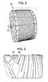
- Figs. 2 and 3 illustrate an exemplary embodiment of a drum member 202 having an axis of rotation 201.
- the drum member includes an outer portion having a surface 204 that defines an outer diameter of the drum member 202.
- the drum member 202 includes an alignment portion 206 that aligns plates of the brush seal assembly 102 (of fig. 1 ).
- the illustrated embodiment includes an alignment portion 206 having channels that are machined in the drum member 202.
- Embodiments may include other alignment features such as, for example, pins, notches, grooves, or recesses.
- the alignment portion 206 is orientated at an angle relative to the axis of rotation 201 and follows the curvature of the drum member 202.
- the angle corresponds to the bristle lay angle of the completed brush seal assembly 102 and is determined in part by the design specifications of the brush seal assembly 102.
- the alignment portion 206 follows the curvature of the drum member 202, such that the alignment portion 206 is a helical shape.
- Fig. 4 illustrates an exemplary embodiment of a back plate 304 and a front plate 302 of the brush seal assembly 102 (of fig. 1 ).
- the back plate 304 and front plate 302 secure bristles of the brush seal assembly 102. When assembled, bristles are sandwiched between the back plate 304 and front plate 302, and the back plate 304, front plate 302, and bristles are held together with a weld or a braze.
- the back plate 304 and front plate 302 are fabricated from material (e.g., stainless steal, carbon steal, cobalt based alloy, nickel based alloy, aluminum alloy, titanium alloy, copper alloy) having a rectangular profile that may be machined in later processes.
- the back plate 304 and front plate 302 include alignment features 306 that may include for example, holes, slots, or notches. Slotted holes may be used to accommodate thermal expansion which may occur during welding.
- the alignment features are used to align the back plate 304 and front plate 302 with the alignment portion 206 of the drum member 202.
- the back plate 304 and front plate 302 may be disposed along an edge of the groves in the drum member 202 and secured using hardware. Since the alignment portion 206 secures the back plate 304 and front plate 302 along a helical shaped curve, the back plate 304 and front plate 302 are bent to match the helical shaped curve of the alignment portion 206.
- the back plate 304 and front plate 302 may be bent using, for example, a die press or rollers.
- Fig. 5 illustrates a portion of the drum member 202 with a plurality of back plates 304 disposed in the alignment portions 206.
- the back plates 304 conform to the helical shape of the alignment portions 206.
- the alignment portions 206 may include pins 404 that engage the alignment features 306.
- the back plates 304 may be secured to the drum member 202 with fasteners, clamps, or other securing techniques.
- the drum member 202 also includes a plurality of cutting channels 406 that are machined along a helical shape similar to the alignment portions 206. The cutting channels 406 facilitate the cutting of wire (discussed below).
- Figs. 6 and 7 illustrate the drum member 202 wrapped with wire 502.
- the winding process includes placing the drum member 202 in a winding apparatus, such as, for example, a winding machine, nc lathe, or manual pitch lathe.
- the drum member 202 is turned along the axis of rotation 201, and a multi-spool wire payout system winds the wire 502 around the back plates 304 and the drum member 202.
- the multi-spool wire payout system precisely spaces wraps of the wire 502 at a pitch relative to the axis of rotation 201.
- Distal ends of the back plates 304 remain unwrapped with the wire 502 to allow space for the alignment features 306. The unwrapped ends of the back plates 304 will be removed in a later process.
- Figs. 8 and 9 illustrate the placement of the front plates 302 once the drum member 202 has been wrapped with the wire 502.
- the front plates 302 are disposed on the wire 502 and are aligned and secured with the alignment portions 206 and the alignment features 306.
- alignment portions 206 extend radially from the outside diameter of the drum and are used to align the distal ends of the front plate 302 with the back plate 304.
- the bonding may include welding using for example, an electron beam weld or a laser weld.
- Fig. 12 illustrates a side cut away view of an embodiment of a clamp used in the bonding process.
- a helical clamp 702 is clamped to the drum member 202 at the brush locations.
- the helical clamp 702 is secured to ends of the drum member 202.
- the helical clamp 702 imparts force along the length of the front plates 302 of adjacent brushes that compresses the front plates 302, the wire 502, and the back plates 304.
- the compression provides sufficient contact of the components for bonding.
- the helical clamp 702 includes a body portion 704, a clamp portion 706, and a rope seal portion 708.
- the body portion 704 provides a surface to secure the helical clamp 702 to the drum assembly 202, and in the illustrated embodiment, includes cavities that secure clamp portions 706.
- a plurality of clamp portions 706 may be used to provide a uniform compression along the length of the front plate 302.
- the clamp portions 706 in the illustrated embodiment are spring plungers that use a spring to apply clamping force.
- Other embodiments may include clamp portions 706 that include, for example, set screws, jacking screws, spring loaded helical bar segments, or pneumatic or hydraulic actuated clamps.
- a weld 710 is shown in fig. 12 .
- the weld 710 bonds the front plate 302, the wire 502, and the back plate 304 together.
- the compression provided by the helical clamps 702 ensures a minimum gap between the front plate 302, the wire 502, and the back plate 304 during thermal expansion caused by the bonding process.
- the illustrated embodiment of the weld 710 is an energy beam weld such as, for example, an electron beam or a laser beam weld through the front plate 302 and the back plate 304.
- the shrinkage of the weld 710 pulls the front plate 302 and the back plate 304 together-reducing the gap between the front plate 302 the wire 502 and the back plate 304.
- the weld 710 and the use of a beam welding process that allows control of the shape of the weld 710 and the heat used in welding reduces distortion of the brush assembly 102.
- the wire 502 may be cut to partially form the brush assembly 102.
- the rope seal portion 708 is disposed in a second cavity of the body portion 704 or on a separate clamp 720 and facilitates the cutting process.
- the rope seal portion 708 is a temperature resistant compliant material that tightly secures the wire 502 in the cutting process.
- the rope seal portion 708 also protects the wire 502 from possible weld splatter during the bonding process.
- the cuts may be performed by, for example, a laser cutting process, a plasma cutting process, or a mechanical cutting process.
- the cutting channels 406 improve the cutting process by providing space for a clean cut, and for wire debris resulting from the cutting process to rest.
- Fig. 13 illustrates a side cut away view of an alternate exemplary arrangement of the helical clamp 702 used in the bonding process.
- the illustrated embodiment of fig. 13 includes two helical clamps 702 used to compress the front plate 302, the wire 502, and the back plate 304 together when additional clamping force is desired.
- Fig. 14 illustrates a side cut away view of another alternate exemplary embodiment of a helical clamp 902.
- the helical clamp 902 includes a body portion 904, a clamp portion 906, and a rope seal portion 908.
- the helical clamp 902 functions similarly to the exemplary embodiment of the helical clamp 702 described above, however, rope seal portion 908 is not secured in the body portion 904, and is secured in a separate rope seal body portion 911.
- the geometry of the body portion 904 allows a weld 910 to be made along the longitudinal edge of the front plate 302 and the back plate 304 on an angle (a) to bond the front plate 302, the wire 502, and the back plate 304.
- a relief cavity 913 may be included in the drum member 202 surface 204 to allow clearance for the bonding process and a space for cutting the wire 502 (described below).
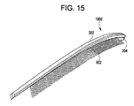
- Fig. 15 illustrates a perspective view of an example of a brush assembly 1000 that includes the assembled front plate 302, the wire 502, and the back plate 304 following the bonding and cutting processes.
- the brush assembly 1000 is curved in a helical shape and will be straightened and flattened to form a straight stock.
- Fig. 16 illustrates an example of a method for straightening and flattening the brush assembly 1000.
- the method for straightening and flattening the brush assembly 1000 includes processing the brush assembly 1000 with a roll bender 1100 having dies 1102 that straighten and flatten the brush assembly 1000.
- the roll bender 1100 may include any number of dies, and the process may be repeated until the brush assembly 1000 is within designed straightness and flatness tolerances.
- the roll setup may include guides that allow feeding the brush into the rollers at a prescribed angle to facilitate proper flattening from the helix.
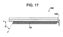
- Fig. 17 illustrates a front view of an example of a brush assembly 1000.
- the brush assembly 1000 is a flat and straight assembly that is processed to form a component in the brush seal assembly 102 (of fig. 1 ).
- the brush assembly may be machined to desired stock dimensions. For example, the length, width, and depth dimensions of the bonded front plate 302, the wire 502, and the back plate 304 (frame 1200) may be decreased, and the bristle length (b l ') of the wire 502 may be cut to a desired size.
- the bristle lay angle ( ⁇ ) is illustrated as the angle between the frame 1200 and the bristles 108.
- Figs. 18-20 illustrate the dimensions of the drum member 202 (of fig. 2 ) that are used to design a drum member 202 having the proper diameter, width, and alignment portions 206 to fabricate a desired brush assembly 1000.
- the helix angle is supplementary to the desired bristle lay angle ( ⁇ ) (of fig. 17 ).
- Figs. 21-24 illustrate front and bottom views of a wire stack of bristles 108 of the brush assembly 1000 and brush seal design parameters that may be varied in the fabrication process to result in a uniform and precise spacing of the bristles 108. The uniform and precise spacing of the bristles is difficult to obtain with previous fabrication methods.
- a bottom view of a portion of the wire stack of bristles 108 of the brush assembly 1000 is shown. The bottom view illustrates a wire strand spacing distance (s) and a wire strand stack distance (m).
- Fig. 21 illustrates a front view of a portion of the brush assembly 1000 when the brush assembly 1000 is in a straight stock shape.
- the bristles 108 have a length (l), are spaced at a distance (g) and lie at and angle ( ⁇ ).
- the winding process (described above) uses a precision winding apparatus that allows precise spacing of the wire as the wire is wrapped on the drum member 202 (of fig. 2 ). The precise spacing allows the distance (g) to be controlled within small tolerances. The precise spacing of the wire strands increases the effectiveness of the designed brush seal.
- Fig. 22 shows a portion of the brush assembly 1000 that has been curved to a diameter (h).
- the precise spacing (g) facilitated by the methods described above allow the (g') and (g") distances to meet desired design specifications.
- stock brush assemblies 1000 may be further processed to fabricate a brush seal assembly to desired specifications similar to the example of a brush seal assembly 102 (of fig. 1 ).
- the further processing may include, for example, bending the brush assembly 1000 and removing material from the front plate 302, the back plate 304, or cutting the bristles 108 to meet design specifications of the desired brush seal assembly 102.
- Fig. 25 illustrates an example of a method for bending the brush assembly 1000 radially to a designed hook diameter of a brush seal.
- the method includes processing the brush assembly 1000 with a roll bender 1500 having dies 1502 that bend the brush assembly 1000 to a desired hook diameter.
- the roll bender 1500 may include any number of dies 1502, and the process may be repeated until the brush assembly 1000 is within designed tolerances.
- the illustrated embodiment includes dies 1502 that include groves 1504 that guide the plates of the brush assembly 1000. Some of the dies 1502 may include a groove 1506 that allows the bristles 108 of the brush assembly 1000 to pass through the roll bender 1500 without crushing the bristles 108.
- Other types of apparatuses may be used to bend the brush assembly 1000 including, for example press brakes.
- plates may be fabricated and attached to the brush assembly 1000.
- the plates may be fabricated from stock materials such as, for example steel plate stock and cut to desired dimensions using various methods such as, for example, cnc punch, conventional machine, laser cutting, water jet cutting, plasma cutting, or wire edm.
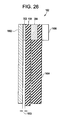
- Fig. 26 illustrates a side partially cut away view of an exemplary embodiment of the brush seal assembly 102 (of fig. 1 ).
- a forward plate 1602 has been attached to the front plate 302.
- the front plate 302 may be machined in a previous process to define a dimension of a front plate gap 1603.
- the front plate gap 1603 is defined by the final thickness of front plate 302.
- a pressure plate 1604 is attached to the back plate 304.
- An alignment portion 1606 is attached to the pressure plate 1604.
- the alignment portion 1606 is used to align the brush seal assembly 102 for installation.
- the embodiment of the brush seal assembly 102 includes the forward plate 1602 and the pressure plate 1604. Alternate embodiments may include a brush seal assembly 1029 having only the forward plate 1602 and no pressure plate 1604, or a brush seal assembly 1028 having only the pressure plate 1604 and no forward plate 1602.
- Fig. 27 illustrates a perspective view of an alternate exemplary embodiment of a brush seal assembly 102.
- the brush seal assembly 102 includes the front plate 302, the wire bristles 108, and the back plate 304.
- the front plate 302, the wire bristles 108, and the back plate 304 may be fabricated using the methods described above, or may be fabricated using other methods.
- the forward plate 1602 includes a castellated top edge 1701 that defines notches having a notch surface 1703 in the plate 1602.
- the castellated top edge 1701 may be formed using a suitable cutting process, that may include, for example, cnc punch, conventional machine, laser cutting, water-jet, plasma cut, or wire edm.
- the forward plate 1602 is attached to a surface 1705 of the front plate 302 with a fillet weld 1702.
- the fillet weld 1702 is applied to the notch surface 1703 and the surface 1705 of the front plate 302. As the fillet weld 1702 cools, the forward plate 1602 is pulled into parallel alignment with the surface 1705 of the front plate 302.
- the pressure plate 1604 may be fabricated to include a castellated top edge similar to the castellated top edge of 1701 of the forward plate 1602.
- the pressure plate 1604 may be attached to the back plate 304 using fillet welds similar to the fillet weld 1702.
Landscapes
- Engineering & Computer Science (AREA)
- General Engineering & Computer Science (AREA)
- Mechanical Engineering (AREA)
- Sealing Devices (AREA)
- Turbine Rotor Nozzle Sealing (AREA)
- Brushes (AREA)
Applications Claiming Priority (1)
| Application Number | Priority Date | Filing Date | Title |
|---|---|---|---|
| US12/366,831 US8051563B2 (en) | 2009-02-06 | 2009-02-06 | Systems and methods and apparatus involving fabricating brush seals |
Publications (3)
| Publication Number | Publication Date |
|---|---|
| EP2224152A2 true EP2224152A2 (de) | 2010-09-01 |
| EP2224152A3 EP2224152A3 (de) | 2012-05-23 |
| EP2224152B1 EP2224152B1 (de) | 2013-07-10 |
Family
ID=42238623
Family Applications (1)
| Application Number | Title | Priority Date | Filing Date |
|---|---|---|---|
| EP20100152252 Active EP2224152B1 (de) | 2009-02-06 | 2010-02-01 | Systeme- und Verfahren und Vorrichtungen zur Herstellung von Bürstendichtungen |
Country Status (4)
| Country | Link |
|---|---|
| US (2) | US8051563B2 (de) |
| EP (1) | EP2224152B1 (de) |
| JP (1) | JP5631601B2 (de) |
| RU (1) | RU2516083C2 (de) |
Cited By (1)
| Publication number | Priority date | Publication date | Assignee | Title |
|---|---|---|---|---|
| CN103192175A (zh) * | 2012-01-04 | 2013-07-10 | 通用电气公司 | 密封组件和用于组装涡轮的方法 |
Families Citing this family (13)
| Publication number | Priority date | Publication date | Assignee | Title |
|---|---|---|---|---|
| US8051563B2 (en) * | 2009-02-06 | 2011-11-08 | General Electric Company | Systems and methods and apparatus involving fabricating brush seals |
| US8505923B2 (en) * | 2009-08-31 | 2013-08-13 | Sealeze, A Unit of Jason, Inc. | Brush seal with stress and deflection accommodating membrane |
| US20120326393A1 (en) * | 2011-06-27 | 2012-12-27 | General Electric Company | Brush seal |
| US9528384B2 (en) * | 2011-06-27 | 2016-12-27 | General Electric Company | Brush seal |
| US10330348B2 (en) | 2012-02-17 | 2019-06-25 | David Alan McBay | Closed-loop geothermal energy collection system |
| US9181931B2 (en) | 2012-02-17 | 2015-11-10 | David Alan McBay | Geothermal energy collection system |
| CN103143656B (zh) * | 2013-02-04 | 2015-07-01 | 沈阳黎明航空零部件制造有限公司 | 一种排丝机和用该排丝机制作刷式密封装置的方法 |
| US9587505B2 (en) | 2013-12-05 | 2017-03-07 | General Electric Company | L brush seal for turbomachinery application |
| US9322287B2 (en) | 2014-06-03 | 2016-04-26 | General Electric Company | Brush seal for turbine |
| US9896955B2 (en) * | 2015-04-13 | 2018-02-20 | United Technologies Corporation | Static axial brush seal with dual bristle packs |
| DE102015208224B4 (de) | 2015-05-05 | 2020-07-09 | MTU Aero Engines AG | Verfahren zur Herstellung von Bürstendichtungen mit schräggestellten Borsten und eine entsprechende Vorrichtung |
| DE102016200343A1 (de) | 2016-01-14 | 2017-07-20 | MTU Aero Engines AG | Verfahren zum Herstellen einer Bürstendichtung mit schräg gestellten Borsten |
| CN115435625B (zh) * | 2022-04-28 | 2024-10-01 | 上海电气集团股份有限公司 | 一种余热回收装置及余热回收方法 |
Family Cites Families (29)
| Publication number | Priority date | Publication date | Assignee | Title |
|---|---|---|---|---|
| US4204629A (en) * | 1977-07-20 | 1980-05-27 | Rolls-Royce Limited | Brush seal and a method of manufacture |
| DE2921512A1 (de) * | 1978-05-31 | 1979-12-13 | Cross Mfg Co 1938 Ltd | Verfahren zur herstellung einer buerstendichtung |
| GB8504331D0 (en) * | 1985-02-20 | 1985-03-20 | Rolls Royce | Brush seals |
| GB8504330D0 (en) * | 1985-02-20 | 1985-03-20 | Rolls Royce | Brush seal manufacture |
| DE3606284A1 (de) * | 1985-07-31 | 1987-02-12 | Mtu Muenchen Gmbh | Verfahren zur herstellung einer buerstendichtung und vorrichtung zur durchfuehrung des verfahrens |
| SU1462916A1 (ru) * | 1987-06-15 | 1996-10-10 | В.Е. Резник | Способ изготовления щеточного уплотнения |
| SU1462917A1 (ru) * | 1987-06-22 | 1996-11-27 | В.И. Цибизов | Способ изготовления щеточного уплотнения и рамочная катушка для его осуществления |
| GB2217237B (en) * | 1988-04-05 | 1992-12-23 | Rolls Royce Plc | Apparatus for and method of manufacturing brush seals |
| SU1665136A1 (ru) * | 1989-07-11 | 1991-07-23 | Куйбышевский авиационный институт им.акад.С.П.Королева | Щеточное уплотнение |
| US5165758A (en) * | 1991-08-07 | 1992-11-24 | Technetics Corporation | Place and bundle method for the manufacture of brush seals |
| US5183197A (en) * | 1991-08-07 | 1993-02-02 | Technetics Corp. | Bundle and place method for the manufacture of brush seals |
| US5403071A (en) * | 1993-11-24 | 1995-04-04 | United Technologies Corporation | Method of brush seal tufting |
| US5556172A (en) * | 1994-05-11 | 1996-09-17 | Technetics Corporation | Brush seal bristle cutting method |
| US5678898A (en) * | 1995-04-17 | 1997-10-21 | General Electric Company | Method for making a brush seal |
| DE19613510C1 (de) * | 1996-04-04 | 1997-04-24 | Mtu Muenchen Gmbh | Bürstendichtung mit einem von Borstenbündeln umschlungenen Kernring |
| DE19641374C1 (de) * | 1996-10-08 | 1997-12-18 | Mtu Muenchen Gmbh | Verfahren zur Herstellung von Bürstendichtungen und Vorrichtung zur Durchführung des Verfahrens |
| DE19641375C1 (de) | 1996-10-08 | 1997-12-04 | Mtu Muenchen Gmbh | Herstellungsverfahren für und Vorrichtung zum Herstellen von Bürstendichtungen |
| US6231047B1 (en) * | 1998-05-29 | 2001-05-15 | Eg&G Engineered Products | Brush seal |
| US6257588B1 (en) * | 1998-09-22 | 2001-07-10 | General Electric Company | Brush seal and rotary machine including such brush seal |
| RU2210694C2 (ru) * | 2001-10-01 | 2003-08-20 | Федеральное государственное унитарное предприятие "Центральный институт авиационного моторостроения" им. П.И.Баранова | Способ изготовления щеточного уплотнения и устройство для его осуществления |
| US6996885B2 (en) * | 2002-03-20 | 2006-02-14 | United Technologies Corporation | Method of making bristle arrangement for brush seal |
| US7334311B2 (en) * | 2004-11-03 | 2008-02-26 | United Technologies Corporation | Method of forming a nested can brush seal |
| US7255352B2 (en) | 2005-09-29 | 2007-08-14 | General Electric Company | Pressure balanced brush seal |
| US7653993B2 (en) * | 2005-09-29 | 2010-02-02 | General Electric Company | Method of manufacturing a brush seal for sealing between stationary and rotary components |
| US7565729B2 (en) * | 2006-03-17 | 2009-07-28 | General Electric Company | Methods of manufacturing a segmented brush seal for sealing between stationary and rotary components |
| US7735833B2 (en) * | 2006-11-14 | 2010-06-15 | The University Of Akron | Double padded finger seal |
| EP2137437A2 (de) * | 2007-03-15 | 2009-12-30 | Rexnord Industries, LLC | Bürstendichtungsanordnung und herstellungsverfahren |
| US8051563B2 (en) * | 2009-02-06 | 2011-11-08 | General Electric Company | Systems and methods and apparatus involving fabricating brush seals |
| US8919633B2 (en) * | 2012-01-04 | 2014-12-30 | General Electric Company | Seal assembly and method for assembling a turbine |
-
2009
- 2009-02-06 US US12/366,831 patent/US8051563B2/en active Active
-
2010
- 2010-02-01 EP EP20100152252 patent/EP2224152B1/de active Active
- 2010-02-02 JP JP2010020822A patent/JP5631601B2/ja active Active
- 2010-02-05 RU RU2010105077/06A patent/RU2516083C2/ru active
-
2011
- 2011-07-18 US US13/185,266 patent/US8925199B2/en active Active
Non-Patent Citations (1)
| Title |
|---|
| None |
Cited By (3)
| Publication number | Priority date | Publication date | Assignee | Title |
|---|---|---|---|---|
| CN103192175A (zh) * | 2012-01-04 | 2013-07-10 | 通用电气公司 | 密封组件和用于组装涡轮的方法 |
| CN103192175B (zh) * | 2012-01-04 | 2016-06-22 | 通用电气公司 | 密封组件和用于组装涡轮的方法 |
| EP2613007A3 (de) * | 2012-01-04 | 2018-03-21 | General Electric Company | Dichtungsbaugruppe und Verfahren zur Montage einer Turbine |
Also Published As
| Publication number | Publication date |
|---|---|
| US20110272891A1 (en) | 2011-11-10 |
| JP2010190422A (ja) | 2010-09-02 |
| US8925199B2 (en) | 2015-01-06 |
| RU2516083C2 (ru) | 2014-05-20 |
| JP5631601B2 (ja) | 2014-11-26 |
| EP2224152A3 (de) | 2012-05-23 |
| RU2010105077A (ru) | 2011-08-10 |
| US20100201073A1 (en) | 2010-08-12 |
| EP2224152B1 (de) | 2013-07-10 |
| US8051563B2 (en) | 2011-11-08 |
Similar Documents
| Publication | Publication Date | Title |
|---|---|---|
| EP2224152B1 (de) | Systeme- und Verfahren und Vorrichtungen zur Herstellung von Bürstendichtungen | |
| US10637336B2 (en) | Stator coil forming method | |
| EP0740403A1 (de) | Verfahren zur Herstellung von Motorstatoren | |
| CN1902801B (zh) | 定子的制造方法以及通过该方法制造的定子 | |
| US5778512A (en) | Manufacturing method for a rotor of an electric rotary machine | |
| US4102040A (en) | Method of manufacturing a curved component of a magnetic circuit | |
| JP5491229B2 (ja) | コンプライアントプレートシールの製造方法 | |
| EP1129517A2 (de) | Verfahren zur herstellung eines stators und/oder eines rotors, stator und rotor und elektrische maschine mit einem rotor und einem stator | |
| US2845555A (en) | Motors | |
| US8042256B2 (en) | Dynamoelectric machine and manufacturing method for stator used therein | |
| US7030525B2 (en) | Method for manufacturing motor yoke, motor yoke, and motor | |
| EP1825589B1 (de) | Fertigungseinrichtung und verfahren zur herstellung eines elektromagnetischen elements für eine elektrische maschine | |
| EP0795096B1 (de) | Herstellung von bürstendichtungen | |
| JP5827956B2 (ja) | 金属マトリックス複合材料製の直線状インサートの製造方法 | |
| JP6094146B2 (ja) | 回転電機の固定子鉄心の製造方法 | |
| GB2419475A (en) | Laminated structure of an electric machine with cooling fluid flow paths | |
| JP6477331B2 (ja) | 回転電機の固定子鉄心の製造方法および製造装置 | |
| CN103688451B (zh) | 背铁及制造背铁的方法 | |
| JP7488103B2 (ja) | パイプ斜材の接合固着方法及び接合固着構造 | |
| EP2158996A1 (de) | Verfahren zum Verbinden von Artikeln | |
| SU1024185A1 (ru) | Способ изготовлени иглофрезы | |
| US20110234349A1 (en) | Pencil core |
Legal Events
| Date | Code | Title | Description |
|---|---|---|---|
| PUAI | Public reference made under article 153(3) epc to a published international application that has entered the european phase |
Free format text: ORIGINAL CODE: 0009012 |
|
| AK | Designated contracting states |
Kind code of ref document: A2 Designated state(s): AT BE BG CH CY CZ DE DK EE ES FI FR GB GR HR HU IE IS IT LI LT LU LV MC MK MT NL NO PL PT RO SE SI SK SM TR |
|
| AX | Request for extension of the european patent |
Extension state: AL BA RS |
|
| RIC1 | Information provided on ipc code assigned before grant |
Ipc: F16J 15/32 20060101AFI20120124BHEP |
|
| PUAL | Search report despatched |
Free format text: ORIGINAL CODE: 0009013 |
|
| AK | Designated contracting states |
Kind code of ref document: A3 Designated state(s): AT BE BG CH CY CZ DE DK EE ES FI FR GB GR HR HU IE IS IT LI LT LU LV MC MK MT NL NO PL PT RO SE SI SK SM TR |
|
| AX | Request for extension of the european patent |
Extension state: AL BA RS |
|
| RIC1 | Information provided on ipc code assigned before grant |
Ipc: F16J 15/32 20060101AFI20120413BHEP |
|
| 17P | Request for examination filed |
Effective date: 20121123 |
|
| GRAP | Despatch of communication of intention to grant a patent |
Free format text: ORIGINAL CODE: EPIDOSNIGR1 |
|
| GRAS | Grant fee paid |
Free format text: ORIGINAL CODE: EPIDOSNIGR3 |
|
| GRAA | (expected) grant |
Free format text: ORIGINAL CODE: 0009210 |
|
| AK | Designated contracting states |
Kind code of ref document: B1 Designated state(s): AT BE BG CH CY CZ DE DK EE ES FI FR GB GR HR HU IE IS IT LI LT LU LV MC MK MT NL NO PL PT RO SE SI SK SM TR |
|
| REG | Reference to a national code |
Ref country code: GB Ref legal event code: FG4D |
|
| REG | Reference to a national code |
Ref country code: CH Ref legal event code: EP Ref country code: AT Ref legal event code: REF Ref document number: 621159 Country of ref document: AT Kind code of ref document: T Effective date: 20130715 |
|
| REG | Reference to a national code |
Ref country code: IE Ref legal event code: FG4D |
|
| REG | Reference to a national code |
Ref country code: DE Ref legal event code: R096 Ref document number: 602010008337 Country of ref document: DE Effective date: 20130905 |
|
| PG25 | Lapsed in a contracting state [announced via postgrant information from national office to epo] |
Ref country code: SI Free format text: LAPSE BECAUSE OF FAILURE TO SUBMIT A TRANSLATION OF THE DESCRIPTION OR TO PAY THE FEE WITHIN THE PRESCRIBED TIME-LIMIT Effective date: 20130710 |
|
| REG | Reference to a national code |
Ref country code: AT Ref legal event code: MK05 Ref document number: 621159 Country of ref document: AT Kind code of ref document: T Effective date: 20130710 |
|
| REG | Reference to a national code |
Ref country code: NL Ref legal event code: VDEP Effective date: 20130710 |
|
| REG | Reference to a national code |
Ref country code: LT Ref legal event code: MG4D |
|
| PG25 | Lapsed in a contracting state [announced via postgrant information from national office to epo] |
Ref country code: HR Free format text: LAPSE BECAUSE OF FAILURE TO SUBMIT A TRANSLATION OF THE DESCRIPTION OR TO PAY THE FEE WITHIN THE PRESCRIBED TIME-LIMIT Effective date: 20130710 Ref country code: CY Free format text: LAPSE BECAUSE OF FAILURE TO SUBMIT A TRANSLATION OF THE DESCRIPTION OR TO PAY THE FEE WITHIN THE PRESCRIBED TIME-LIMIT Effective date: 20130904 Ref country code: PT Free format text: LAPSE BECAUSE OF FAILURE TO SUBMIT A TRANSLATION OF THE DESCRIPTION OR TO PAY THE FEE WITHIN THE PRESCRIBED TIME-LIMIT Effective date: 20131111 Ref country code: AT Free format text: LAPSE BECAUSE OF FAILURE TO SUBMIT A TRANSLATION OF THE DESCRIPTION OR TO PAY THE FEE WITHIN THE PRESCRIBED TIME-LIMIT Effective date: 20130710 Ref country code: BE Free format text: LAPSE BECAUSE OF FAILURE TO SUBMIT A TRANSLATION OF THE DESCRIPTION OR TO PAY THE FEE WITHIN THE PRESCRIBED TIME-LIMIT Effective date: 20130710 Ref country code: LT Free format text: LAPSE BECAUSE OF FAILURE TO SUBMIT A TRANSLATION OF THE DESCRIPTION OR TO PAY THE FEE WITHIN THE PRESCRIBED TIME-LIMIT Effective date: 20130710 Ref country code: NO Free format text: LAPSE BECAUSE OF FAILURE TO SUBMIT A TRANSLATION OF THE DESCRIPTION OR TO PAY THE FEE WITHIN THE PRESCRIBED TIME-LIMIT Effective date: 20131010 Ref country code: IS Free format text: LAPSE BECAUSE OF FAILURE TO SUBMIT A TRANSLATION OF THE DESCRIPTION OR TO PAY THE FEE WITHIN THE PRESCRIBED TIME-LIMIT Effective date: 20131110 Ref country code: SE Free format text: LAPSE BECAUSE OF FAILURE TO SUBMIT A TRANSLATION OF THE DESCRIPTION OR TO PAY THE FEE WITHIN THE PRESCRIBED TIME-LIMIT Effective date: 20130710 |
|
| PG25 | Lapsed in a contracting state [announced via postgrant information from national office to epo] |
Ref country code: FI Free format text: LAPSE BECAUSE OF FAILURE TO SUBMIT A TRANSLATION OF THE DESCRIPTION OR TO PAY THE FEE WITHIN THE PRESCRIBED TIME-LIMIT Effective date: 20130710 Ref country code: PL Free format text: LAPSE BECAUSE OF FAILURE TO SUBMIT A TRANSLATION OF THE DESCRIPTION OR TO PAY THE FEE WITHIN THE PRESCRIBED TIME-LIMIT Effective date: 20130710 Ref country code: ES Free format text: LAPSE BECAUSE OF FAILURE TO SUBMIT A TRANSLATION OF THE DESCRIPTION OR TO PAY THE FEE WITHIN THE PRESCRIBED TIME-LIMIT Effective date: 20131021 Ref country code: NL Free format text: LAPSE BECAUSE OF FAILURE TO SUBMIT A TRANSLATION OF THE DESCRIPTION OR TO PAY THE FEE WITHIN THE PRESCRIBED TIME-LIMIT Effective date: 20130710 Ref country code: GR Free format text: LAPSE BECAUSE OF FAILURE TO SUBMIT A TRANSLATION OF THE DESCRIPTION OR TO PAY THE FEE WITHIN THE PRESCRIBED TIME-LIMIT Effective date: 20131011 Ref country code: LV Free format text: LAPSE BECAUSE OF FAILURE TO SUBMIT A TRANSLATION OF THE DESCRIPTION OR TO PAY THE FEE WITHIN THE PRESCRIBED TIME-LIMIT Effective date: 20130710 |
|
| PG25 | Lapsed in a contracting state [announced via postgrant information from national office to epo] |
Ref country code: CY Free format text: LAPSE BECAUSE OF FAILURE TO SUBMIT A TRANSLATION OF THE DESCRIPTION OR TO PAY THE FEE WITHIN THE PRESCRIBED TIME-LIMIT Effective date: 20130710 |
|
| PG25 | Lapsed in a contracting state [announced via postgrant information from national office to epo] |
Ref country code: RO Free format text: LAPSE BECAUSE OF FAILURE TO SUBMIT A TRANSLATION OF THE DESCRIPTION OR TO PAY THE FEE WITHIN THE PRESCRIBED TIME-LIMIT Effective date: 20130710 Ref country code: CZ Free format text: LAPSE BECAUSE OF FAILURE TO SUBMIT A TRANSLATION OF THE DESCRIPTION OR TO PAY THE FEE WITHIN THE PRESCRIBED TIME-LIMIT Effective date: 20130710 Ref country code: SK Free format text: LAPSE BECAUSE OF FAILURE TO SUBMIT A TRANSLATION OF THE DESCRIPTION OR TO PAY THE FEE WITHIN THE PRESCRIBED TIME-LIMIT Effective date: 20130710 Ref country code: DK Free format text: LAPSE BECAUSE OF FAILURE TO SUBMIT A TRANSLATION OF THE DESCRIPTION OR TO PAY THE FEE WITHIN THE PRESCRIBED TIME-LIMIT Effective date: 20130710 Ref country code: EE Free format text: LAPSE BECAUSE OF FAILURE TO SUBMIT A TRANSLATION OF THE DESCRIPTION OR TO PAY THE FEE WITHIN THE PRESCRIBED TIME-LIMIT Effective date: 20130710 |
|
| PLBE | No opposition filed within time limit |
Free format text: ORIGINAL CODE: 0009261 |
|
| STAA | Information on the status of an ep patent application or granted ep patent |
Free format text: STATUS: NO OPPOSITION FILED WITHIN TIME LIMIT |
|
| PG25 | Lapsed in a contracting state [announced via postgrant information from national office to epo] |
Ref country code: IT Free format text: LAPSE BECAUSE OF FAILURE TO SUBMIT A TRANSLATION OF THE DESCRIPTION OR TO PAY THE FEE WITHIN THE PRESCRIBED TIME-LIMIT Effective date: 20130710 |
|
| 26N | No opposition filed |
Effective date: 20140411 |
|
| REG | Reference to a national code |
Ref country code: DE Ref legal event code: R097 Ref document number: 602010008337 Country of ref document: DE Effective date: 20140411 |
|
| PG25 | Lapsed in a contracting state [announced via postgrant information from national office to epo] |
Ref country code: LU Free format text: LAPSE BECAUSE OF FAILURE TO SUBMIT A TRANSLATION OF THE DESCRIPTION OR TO PAY THE FEE WITHIN THE PRESCRIBED TIME-LIMIT Effective date: 20140201 Ref country code: MC Free format text: LAPSE BECAUSE OF FAILURE TO SUBMIT A TRANSLATION OF THE DESCRIPTION OR TO PAY THE FEE WITHIN THE PRESCRIBED TIME-LIMIT Effective date: 20130710 |
|
| REG | Reference to a national code |
Ref country code: CH Ref legal event code: PL |
|
| GBPC | Gb: european patent ceased through non-payment of renewal fee |
Effective date: 20140201 |
|
| PG25 | Lapsed in a contracting state [announced via postgrant information from national office to epo] |
Ref country code: LI Free format text: LAPSE BECAUSE OF NON-PAYMENT OF DUE FEES Effective date: 20140228 Ref country code: CH Free format text: LAPSE BECAUSE OF NON-PAYMENT OF DUE FEES Effective date: 20140228 |
|
| REG | Reference to a national code |
Ref country code: IE Ref legal event code: MM4A |
|
| PG25 | Lapsed in a contracting state [announced via postgrant information from national office to epo] |
Ref country code: IE Free format text: LAPSE BECAUSE OF NON-PAYMENT OF DUE FEES Effective date: 20140201 Ref country code: GB Free format text: LAPSE BECAUSE OF NON-PAYMENT OF DUE FEES Effective date: 20140201 |
|
| REG | Reference to a national code |
Ref country code: FR Ref legal event code: PLFP Year of fee payment: 7 |
|
| PG25 | Lapsed in a contracting state [announced via postgrant information from national office to epo] |
Ref country code: MT Free format text: LAPSE BECAUSE OF FAILURE TO SUBMIT A TRANSLATION OF THE DESCRIPTION OR TO PAY THE FEE WITHIN THE PRESCRIBED TIME-LIMIT Effective date: 20130710 |
|
| PG25 | Lapsed in a contracting state [announced via postgrant information from national office to epo] |
Ref country code: SM Free format text: LAPSE BECAUSE OF FAILURE TO SUBMIT A TRANSLATION OF THE DESCRIPTION OR TO PAY THE FEE WITHIN THE PRESCRIBED TIME-LIMIT Effective date: 20130710 |
|
| PG25 | Lapsed in a contracting state [announced via postgrant information from national office to epo] |
Ref country code: BG Free format text: LAPSE BECAUSE OF FAILURE TO SUBMIT A TRANSLATION OF THE DESCRIPTION OR TO PAY THE FEE WITHIN THE PRESCRIBED TIME-LIMIT Effective date: 20130710 |
|
| PG25 | Lapsed in a contracting state [announced via postgrant information from national office to epo] |
Ref country code: TR Free format text: LAPSE BECAUSE OF FAILURE TO SUBMIT A TRANSLATION OF THE DESCRIPTION OR TO PAY THE FEE WITHIN THE PRESCRIBED TIME-LIMIT Effective date: 20130710 Ref country code: HU Free format text: LAPSE BECAUSE OF FAILURE TO SUBMIT A TRANSLATION OF THE DESCRIPTION OR TO PAY THE FEE WITHIN THE PRESCRIBED TIME-LIMIT; INVALID AB INITIO Effective date: 20100201 |
|
| REG | Reference to a national code |
Ref country code: FR Ref legal event code: PLFP Year of fee payment: 8 |
|
| REG | Reference to a national code |
Ref country code: FR Ref legal event code: PLFP Year of fee payment: 9 |
|
| PG25 | Lapsed in a contracting state [announced via postgrant information from national office to epo] |
Ref country code: MK Free format text: LAPSE BECAUSE OF FAILURE TO SUBMIT A TRANSLATION OF THE DESCRIPTION OR TO PAY THE FEE WITHIN THE PRESCRIBED TIME-LIMIT Effective date: 20130710 |
|
| P01 | Opt-out of the competence of the unified patent court (upc) registered |
Effective date: 20230522 |
|
| REG | Reference to a national code |
Ref country code: DE Ref legal event code: R081 Ref document number: 602010008337 Country of ref document: DE Owner name: GENERAL ELECTRIC TECHNOLOGY GMBH, CH Free format text: FORMER OWNER: GENERAL ELECTRIC COMPANY, SCHENECTADY, NY, US |
|
| PGFP | Annual fee paid to national office [announced via postgrant information from national office to epo] |
Ref country code: DE Payment date: 20260121 Year of fee payment: 17 |
|
| PGFP | Annual fee paid to national office [announced via postgrant information from national office to epo] |
Ref country code: FR Payment date: 20260121 Year of fee payment: 17 |