EP2222995B1 - Line connector for media lines and ready-made media line with at least one such line connector - Google Patents
Line connector for media lines and ready-made media line with at least one such line connector Download PDFInfo
- Publication number
- EP2222995B1 EP2222995B1 EP08865799.4A EP08865799A EP2222995B1 EP 2222995 B1 EP2222995 B1 EP 2222995B1 EP 08865799 A EP08865799 A EP 08865799A EP 2222995 B1 EP2222995 B1 EP 2222995B1
- Authority
- EP
- European Patent Office
- Prior art keywords
- line
- connector
- branch
- fluid
- housing
- Prior art date
- Legal status (The legal status is an assumption and is not a legal conclusion. Google has not performed a legal analysis and makes no representation as to the accuracy of the status listed.)
- Active
Links
- 239000012530 fluid Substances 0.000 claims description 78
- 239000004020 conductor Substances 0.000 claims description 49
- 238000010438 heat treatment Methods 0.000 claims description 47
- 230000007704 transition Effects 0.000 claims description 11
- 150000001875 compounds Chemical class 0.000 claims description 6
- 238000010137 moulding (plastic) Methods 0.000 claims description 3
- 238000005538 encapsulation Methods 0.000 description 28
- 239000004033 plastic Substances 0.000 description 7
- 238000000465 moulding Methods 0.000 description 5
- 230000008901 benefit Effects 0.000 description 3
- 238000010586 diagram Methods 0.000 description 3
- 238000009413 insulation Methods 0.000 description 3
- 230000001419 dependent effect Effects 0.000 description 2
- 238000009826 distribution Methods 0.000 description 2
- 230000008014 freezing Effects 0.000 description 2
- 238000007710 freezing Methods 0.000 description 2
- 238000000034 method Methods 0.000 description 2
- 230000002093 peripheral effect Effects 0.000 description 2
- 230000008569 process Effects 0.000 description 2
- 230000001681 protective effect Effects 0.000 description 2
- 238000007789 sealing Methods 0.000 description 2
- 238000003466 welding Methods 0.000 description 2
- XSQUKJJJFZCRTK-UHFFFAOYSA-N Urea Chemical compound NC(N)=O XSQUKJJJFZCRTK-UHFFFAOYSA-N 0.000 description 1
- 239000000654 additive Substances 0.000 description 1
- 230000000996 additive effect Effects 0.000 description 1
- 238000004026 adhesive bonding Methods 0.000 description 1
- 238000013459 approach Methods 0.000 description 1
- 230000015572 biosynthetic process Effects 0.000 description 1
- 239000004202 carbamide Substances 0.000 description 1
- 239000003054 catalyst Substances 0.000 description 1
- 239000011248 coating agent Substances 0.000 description 1
- 238000000576 coating method Methods 0.000 description 1
- 229920001971 elastomer Polymers 0.000 description 1
- 239000000806 elastomer Substances 0.000 description 1
- 238000009434 installation Methods 0.000 description 1
- 230000014759 maintenance of location Effects 0.000 description 1
- 238000004519 manufacturing process Methods 0.000 description 1
- 230000013011 mating Effects 0.000 description 1
- 239000012778 molding material Substances 0.000 description 1
- 238000004382 potting Methods 0.000 description 1
- 230000009467 reduction Effects 0.000 description 1
- 238000003860 storage Methods 0.000 description 1
- 238000009757 thermoplastic moulding Methods 0.000 description 1
- XLYOFNOQVPJJNP-UHFFFAOYSA-N water Substances O XLYOFNOQVPJJNP-UHFFFAOYSA-N 0.000 description 1
Images


Classifications
-
- F—MECHANICAL ENGINEERING; LIGHTING; HEATING; WEAPONS; BLASTING
- F16—ENGINEERING ELEMENTS AND UNITS; GENERAL MEASURES FOR PRODUCING AND MAINTAINING EFFECTIVE FUNCTIONING OF MACHINES OR INSTALLATIONS; THERMAL INSULATION IN GENERAL
- F16L—PIPES; JOINTS OR FITTINGS FOR PIPES; SUPPORTS FOR PIPES, CABLES OR PROTECTIVE TUBING; MEANS FOR THERMAL INSULATION IN GENERAL
- F16L53/00—Heating of pipes or pipe systems; Cooling of pipes or pipe systems
- F16L53/30—Heating of pipes or pipe systems
- F16L53/35—Ohmic-resistance heating
- F16L53/38—Ohmic-resistance heating using elongate electric heating elements, e.g. wires or ribbons
-
- F—MECHANICAL ENGINEERING; LIGHTING; HEATING; WEAPONS; BLASTING
- F16—ENGINEERING ELEMENTS AND UNITS; GENERAL MEASURES FOR PRODUCING AND MAINTAINING EFFECTIVE FUNCTIONING OF MACHINES OR INSTALLATIONS; THERMAL INSULATION IN GENERAL
- F16L—PIPES; JOINTS OR FITTINGS FOR PIPES; SUPPORTS FOR PIPES, CABLES OR PROTECTIVE TUBING; MEANS FOR THERMAL INSULATION IN GENERAL
- F16L25/00—Constructive types of pipe joints not provided for in groups F16L13/00 - F16L23/00 ; Details of pipe joints not otherwise provided for, e.g. electrically conducting or insulating means
- F16L25/01—Constructive types of pipe joints not provided for in groups F16L13/00 - F16L23/00 ; Details of pipe joints not otherwise provided for, e.g. electrically conducting or insulating means specially adapted for realising electrical conduction between the two pipe ends of the joint or between parts thereof
-
- H—ELECTRICITY
- H05—ELECTRIC TECHNIQUES NOT OTHERWISE PROVIDED FOR
- H05B—ELECTRIC HEATING; ELECTRIC LIGHT SOURCES NOT OTHERWISE PROVIDED FOR; CIRCUIT ARRANGEMENTS FOR ELECTRIC LIGHT SOURCES, IN GENERAL
- H05B3/00—Ohmic-resistance heating
- H05B3/40—Heating elements having the shape of rods or tubes
- H05B3/42—Heating elements having the shape of rods or tubes non-flexible
-
- F—MECHANICAL ENGINEERING; LIGHTING; HEATING; WEAPONS; BLASTING
- F01—MACHINES OR ENGINES IN GENERAL; ENGINE PLANTS IN GENERAL; STEAM ENGINES
- F01N—GAS-FLOW SILENCERS OR EXHAUST APPARATUS FOR MACHINES OR ENGINES IN GENERAL; GAS-FLOW SILENCERS OR EXHAUST APPARATUS FOR INTERNAL COMBUSTION ENGINES
- F01N2240/00—Combination or association of two or more different exhaust treating devices, or of at least one such device with an auxiliary device, not covered by indexing codes F01N2230/00 or F01N2250/00, one of the devices being
- F01N2240/16—Combination or association of two or more different exhaust treating devices, or of at least one such device with an auxiliary device, not covered by indexing codes F01N2230/00 or F01N2250/00, one of the devices being an electric heater, i.e. a resistance heater
-
- F—MECHANICAL ENGINEERING; LIGHTING; HEATING; WEAPONS; BLASTING
- F01—MACHINES OR ENGINES IN GENERAL; ENGINE PLANTS IN GENERAL; STEAM ENGINES
- F01N—GAS-FLOW SILENCERS OR EXHAUST APPARATUS FOR MACHINES OR ENGINES IN GENERAL; GAS-FLOW SILENCERS OR EXHAUST APPARATUS FOR INTERNAL COMBUSTION ENGINES
- F01N2610/00—Adding substances to exhaust gases
- F01N2610/02—Adding substances to exhaust gases the substance being ammonia or urea
-
- F—MECHANICAL ENGINEERING; LIGHTING; HEATING; WEAPONS; BLASTING
- F01—MACHINES OR ENGINES IN GENERAL; ENGINE PLANTS IN GENERAL; STEAM ENGINES
- F01N—GAS-FLOW SILENCERS OR EXHAUST APPARATUS FOR MACHINES OR ENGINES IN GENERAL; GAS-FLOW SILENCERS OR EXHAUST APPARATUS FOR INTERNAL COMBUSTION ENGINES
- F01N2610/00—Adding substances to exhaust gases
- F01N2610/10—Adding substances to exhaust gases the substance being heated, e.g. by heating tank or supply line of the added substance
-
- F—MECHANICAL ENGINEERING; LIGHTING; HEATING; WEAPONS; BLASTING
- F01—MACHINES OR ENGINES IN GENERAL; ENGINE PLANTS IN GENERAL; STEAM ENGINES
- F01N—GAS-FLOW SILENCERS OR EXHAUST APPARATUS FOR MACHINES OR ENGINES IN GENERAL; GAS-FLOW SILENCERS OR EXHAUST APPARATUS FOR INTERNAL COMBUSTION ENGINES
- F01N2610/00—Adding substances to exhaust gases
- F01N2610/14—Arrangements for the supply of substances, e.g. conduits
Definitions
- the present invention relates to a line connector for media lines according to the preamble of claim 1.
- the invention according to claim 16 also relates to a ready-made media line using at least one such line connector.
- Such line connectors serve for the mutual connection of at least two media lines or for the connection connection of at least one line to any desired unit.
- line connectors and media lines can be used in particular in motor vehicles for such media, which already tend to freeze at relatively high ambient temperatures due to their freezing point. This can affect certain functions. This is the case, for example, with water pipes for the windscreen washer system and above all also with lines for an aqueous urea solution which is used as a NO x reduction additive for diesel engines with so-called SCR catalysts. Therefore, at low temperatures, electrical heating means can be activated to prevent freezing or to thaw the already frozen medium.
- a line connector of the preamble of claim 1 corresponding type is in the WO 2007/073286 A1 described.
- an electric heater is attached via a clip element on the outside of the fluid connector.
- a sleeve-shaped transition piece which is disposed between the fluid connector and one end of the fluid conduit enclosing the protective tube and in a Execution has a branch for electrical connection conductors. The heater is therefore exposed and unprotected in the outer region of the fluid connector.
- a cavity is formed, which also serves to receive electrical connections of the heating means.
- the compounds are only loosely housed in this cavity, so that they are insufficiently protected against mechanical and other stresses. Due to the loose, undefined arrangement, the electrical connections could come into contact with each other and possibly cause a short circuit. In addition, the production and installation of the known media line is difficult.
- the present invention is based on the object to provide a line connector of the type mentioned, which ensures good and durable safe performance with simple and process-safe manufacturability.
- a ready-made line should be made available for the same purpose.
- the heating means of the fluid connector which at least partially surround the fluid channel and of at least one over the outer circumference of the Fluid connector extending heating conductor are formed, effectively protected from external influences.
- an additional thermal insulation is achieved to the outside.
- a good and uniform temperature distribution can be achieved by an air gap formed within the enclosure be achieved.
- An at least partial encapsulation also contributes to the heat insulation.
- the encapsulation is also designed to enclose an end region of a fluid line connected to the connection section and also of an end region of a tubular enclosure of the fluid line.
- This envelope is in particular formed by a corrugated tube whose end region is preferably fixed in the encapsulation in a form-fitting manner. All necessary electrical connections between the heating means of the fluid connector, external supply conductors and preferably existing heating means of the fluid line can be accommodated well protected within the enclosure. A particularly effective protection can be achieved by the electrical connections (contact points, stripped points) can be embedded by encapsulation and / or encapsulation in a plastic molding compound.
- the outer supply conductors can be led to the outside via the branch of the encapsulation according to the invention. It is advantageous if the branch for the positive reception of an end portion of a tubular, in particular also formed by a corrugated tube conductor shell is formed for the supply conductor.
- the branch has an electrical connection element, in particular in the form of a plug connection for external supply conductors.
- the connection element is connected within the encapsulation with the heating means of the fluid connector and optionally with heating means of the fluid line.
- the branch is formed as a separate, connected to the encapsulation or connectable branch part.
- This configuration of the branch as a separate branch part advantageously results in different applications. So the encapsulation can basically be used without a branch.
- the branch part can be fixed in the region of an opening of the encapsulation. The opening may be prefabricated or formed by removing a portion of the enclosure. In this case, a wall part can be broken out over predetermined breaking points. The attachment of the branch part takes place in particular via latching means. However, the branch part can also be positively connected to the encapsulation.
- a prefabricated media line 1 which has a line connector 2 according to the invention at both ends.
- each of the two line connectors 2 may optionally be an angle connector (as shown by way of example on the right) or a straight connector (such as shown on the left). This means that on both sides completely any connector geometries are possible.
- the terminal portions of the connectors may have any orientation (eg, also be rotated relative to each other about the line axis).
- the line connector 2 consists of a fluid connector 4 with at least one connection portion 6 for connection to a line end 8a (see Fig. 10 ) of a fluid line 8.
- a transition section 10 connects, which preferably merges into a second connection section 12, which is preferably designed as a plug connection of a fluid plug system.
- the plug connection is designed as a sleeve for receiving a fluid plug, not shown.
- a radially elastic retaining clip 14 is arranged in the region of the sleeve.
- the second connection section 12 can also be designed as a plug.
- the fluid connector 4 on the side of the second connection section 12 can also be connected either directly to any aggregate or analogous to the first connection section 6 for connection to a further (second) fluid line.
- the first connection section 6 is preferably designed as a receptacle for inserting the line end 8a (see in particular FIG Fig. 10 and 17 ), wherein preferably a non-detachable, cohesive connection by gluing, welding or on / encapsulation takes place, in particular by laser welding.
- the fluid connector 4 and the fluid line 8 each consist of a weldable plastic, wherein the fluid connector 4 at least in the region of the first connection portion. 6 is transparent to laser beams.
- the fluid connector 4 has an inner fluid channel 16.
- the fluid connector 4 has electrical heating means 18. These heating means 18 expediently surround the fluid channel 16 at least partially and are for this purpose formed by at least one heating conductor 20 extending over the outer circumference of the fluid connector 4.
- the line connector 2 has an encapsulation 22 enclosing the fluid connector 4 at least in the area of the heating means 18.
- This encapsulation 22 in turn has a pipe-shaped branch 24 for electrical supply conductor 26 for the heating means 18.
- the encapsulation 22 is also designed to enclose an end region of the fluid line 8 connected to the connection section 6 and of an end region of a tubular enclosure 28 of the fluid line 8.
- the sheath 28 can be fixed in particular form-fitting manner within the encapsulation 22.
- the encapsulation 22 has a pipe extension 30 with inner peripheral ribs 32 which engage radially in circumferential grooves 34 of the casing 20, which is formed in particular by a corrugated pipe (parallel corrugated protective pipe, in particular made of plastic).
- the enclosure 22 consists of an outer connector housing 36 having the branch 24.
- This connector housing 36 also has the tube extension 30 for the positive reception of the end region of the envelope 28 of the fluid line 8.
- the encapsulation 22 consists on the one hand of a connector housing 38 and on the other hand, an additional, the branch 24th
- the branch housing 40 consists of a tubular passage section for the fluid line 8 and the branch 24 branching off from the passage section.
- the passage section is connected or connectable directly to the connector housing 38 at one end.
- the branch housing 40 is designed to receive the end region of the sheath 28 of the fluid line 8 in a form-fitting manner.
- this end portion of the branch housing 40 is according to Fig.
- the connector housing 38 and the branch housing 40 have certain engagement contours (see the cut-out enlargement in FIG Fig. 8 ), which may be a relatively rotatable connection, which has the advantage that the branch 24 can be adjusted in terms of its orientation by turning the branch housing 40. Alternatively, it may also be a secured against relative rotation connection, in particular by a deviating from the circular shape engagement cross-section, for example, an oval circumference.
- the two-piece design according to Fig. 8 has the further advantage that the connector housing 38 can be designed arbitrarily, for example, as shown for an angle connector or as a straight connector.
- the branch housing 40 can be universally used for all different versions of the connector housing 38 in the same design.
- the branch housing 40 advantageously comprises two housing half-shells 40a and 40b which are substantially symmetrical with respect to a dividing plane and which can preferably be locked together by latching means 42 (cf. Fig. 12 ).
- the half shells 40a, 40b can be integrally connected to each other via a film hinge 40c, wherein the branch housing 40 can be closed by folding the half shells 40a, 40b.
- the connector housing 36 and 38 is advantageously made of two to a dividing plane substantially symmetrical housing half-shells a and b, which are also preferably locked together via locking means 44.
- the housing half shells 36a, b and 38a, b are formed in the illustrated examples as separate, preferably at least approximately identical moldings.
- analogous to Fig. 9 be provided to form the connector housing 36 and 38 as a one-piece molded part with its hinged, in particular via at least one film hinge (40c) interconnected half shells.
- sealing means such as. B. interlocking sealing contours (eg., In the manner of a tongue and groove connection) or molded soft seals (elastomer coating) have.
- the branch 24 is designed for the positive reception of an end region of a tubular conductor shell 46 for the supply conductor 26.
- the conductor sheath 46 is preferably also a corrugated pipe made of plastic. Therefore, the branch 24 also has an inner engagement contour with at least one radially inwardly projecting circumferential rib 48 (see also FIG FIGS. 22 to 25 ).
- an electrical connection element 50 in particular in the form of a plug connection, fixed for external supply conductor, not shown.
- an outer connector plug or stretched and locked for example via latching means 52.
- the connecting element 50 is connected within the encapsulation 22 to the heating means 18 of the fluid connector 4 and / or possibly to heating means 54 of the connected fluid line 8.
- the fluid line 8 also electrical heating means 54, in particular of at least one helical over the heating medium 56 extending the line circumference are formed.
- the heating conductor 56 is preferably closely together with the fluid line 8 enclosed by a fixing sleeve 57, the z. B. may be formed by a helically wrapped with the inclusion of the heat conductor 56 to the fluid line 8 wound tape.
- the heating conductor 56 may consist of a helical wound from one end of the line to the other end extending lead and a likewise helical or rectilinear return conductor, whereby a good distribution of the heating power is achieved.
- the branch 24 may include a virtually arbitrary angle ⁇ with respect to its branch axis with a connection axis of the fluid line 8, but is preferably in the range of 20 ° to 160 °. In the examples shown, it is an acute-angled Y-branch, but it can also be provided an approximately rectangular T-branch (see Fig. 19 to 21 ). In addition, according to Fig. 28 the branch 24 also have an axis parallel to the connection axis of the line 8.
- the ends of the heating conductors 20, 56 are in particular in the transition region between the fluid connector 4 and the fluid line 8 with each other and / or connected to the external supply conductors 26 via electrical connections 58 (interconnected). These compounds 58 are referred to in the Fig. 2 to 4 referenced possibilities, which will be explained in more detail below.
- the fluid connector 4 and / or the connected fiuid line 8 are partially covered, including the electrical connections 58 of the heating means 18, 54 with a plastic molding compound, in particular with a thermoplastic molding material, for. B. PA-based, surrounded (transformed, for example, overmoulded or potted).
- This molding with plastic takes place in particular in the transition region between the connection section 6 of the fluid connector 4 and the connected fluid line 8.
- the attachment part 60 with respect to its outer contour and the encapsulation 22 with respect to their inner contour adapted to each other so that the attachment portion 60 is positively housed in the enclosure 22.
- the molded-on attachment part 60 preferably also includes an end of the sheath 28 of the fluid line 8 and possibly also an end of the conductor sheath 46 for the supply conductor 26.
- the attachment part 60 integrally formed annular collar 62.
- the attachment part 60 consists of an approximately cylindrical base section 64, which encloses the transition region between the connection section 6 and the fluid line 8. Furthermore, the attachment part 60 may have flange-like or wing-like, diametrically opposed in a plane lugs 66, which emanate from the base portion 64. The lugs 66 cause an effective rotation of the attachment portion 60 within the enclosure 22 and can also be used to accommodate the electrical connections 58 at any point (see. Fig. 3b and 4b ).
- attachment part 60 takes place in a suitable molding tool.
- This tool may, for example, have pin-shaped positioning elements for the electrical connections 58 in order to position them during the molding process in such a way that they are optimally embedded in the plastic.
- touches of the metallic, stripped ends of the heating element should be avoided.
- a remaining space within the encapsulation 22 is then preferably at least partially encapsulated with plastic.
- the encapsulation can have at least one opening 70 (cf. Fig. 1 ) for introducing a plastic potting compound.
- the encapsulation 22 may have, on the outside in the region of the connector housing 36, 38 and / or in the region of the branch housing 40, at least one retaining element 72 for the fixing retention of an electrical connector part 74 (FIG. Fig. 7 and also Fig. 12 ) exhibit.
- the holding member 72 may be formed as a slot as shown. It serves for the temporary fixation of the connector part 74 during storage and transport until the connection of the supply conductor 26 takes place during assembly. It then only takes the connector part 74 removed from the support member 72 and connected to a mating connector, not shown.
- the holder of the connector part 74 can also be done in other suitable manner, in particular non-positively and / or positively or by means of a hook and loop fastener or the like.
- the heating conductor 20 is illustrated as electrical resistance R1.
- the heating conductor or conductors 56 of the fluid line 8 are shown as resistors R2 and R3, which is preferably a forward and return conductor.
- supply conductors 26 can be connected to a series connection of the heating conductors 20 and 56.
- the supply conductors 26 are connected, on the one hand, to a first end of the heating conductor 20 and, on the other hand, to a first end of the heating conductor 56, while the other two ends of the heating conductors 20, 56 are connected directly to one another.
- the interconnection illustrated is a parallel connection of the heating conductors 20 and 56 in that the heating conductors 20 and 56 are connected directly to one another and to one of the supply conductors 26, respectively.
- the branch 24 is part of a separate, connected to the enclosure 22 or connectable branch part 80. This is also on the separate representations in FIGS. 22 to 25 directed.
- the branch portion 80 is preferably releasably (separably) connected or connectable to the connector housing 36.
- FIGS. 22 to 25 In the statements according to Fig. 16 to 25 and also according to Fig. 28 is the branch part 80 in the region of an opening 82 (only in Fig. 17 to recognize) of the connector housing 36 connected thereto via locking means 84 or connectable. As it turned out FIGS. 22 to 25 results, has the branch part 80 to an approximately U-shaped connecting portion which engages over a portion of the connector housing 36, wherein latching arms 86 with latching openings 88 snap lugs 90 overlap positively locking manner.
- the branch part 80 has a connecting portion 92 with a circumferential groove recess 94, with which the branch part 80 can be inserted or inserted in a form-fitting manner between the housing parts 36a and 36b in the region of the opening 82 of the connector housing 36 lying in the plane of division of the housing halves 36a, b.
- the opening 82 of the connector housing 36 may be prefabricated.
- the opening 82 can be produced by removing at least one originally present housing region. It can be wall sections of the housing parts 36a, 36b which can be broken out via predetermined breaking points.
- the branch part 80 for the positive reception of the end portion of the tubular conductor shell 46 for the supply conductor 26 has a tubular receiving portion 96 for the conductor shell 46.
- the receiving portion 96 of diametrically split halves 96a, 96b, wherein one half 96a, including the end of the conductor shell 46 with the other half 96b connectable, in particular can be latched.
- locking means 98 are provided analogous to the locking means 44.
- the halves 96a, 96b can be integrally connected via a film hinge 100 pivotally and thus closable together.
- the receiving portion 96 has in its interior an engagement contour with at least one radially inwardly projecting circumferential rib 32 which engages in a groove of the conductor sheath 46 forming corrugated tube.
- the separate configuration of the branch part 80 is of particular advantage, because according to Fig. 16 on the one hand and Fig. 18 on the other hand, a connection of the branch part 80 with the connector housing 36 is optionally possible in at least two different orientations. As a result, the direction of the branch 24 can be varied. This also applies accordingly to the execution according to Fig. 28 ,
- the invention also applies to the entire assembled media line 1, for example, in an embodiment according to Fig. 12 or 13 refers.
- the cable connector 2 may have all the features already explained.
Description
Die vorliegende Erfindung betrifft einen Leitungsverbinder für Medienleitungen gemäß dem Oberbegriff des Anspruchs 1.The present invention relates to a line connector for media lines according to the preamble of
Weiterhin betrifft die Erfindung gemäß dem Anspruch 16 auch eine konfektionierte Medienleitung unter Verwendung mindestens eines derartigen Leitungsverbinders.Furthermore, the invention according to
Solche Leitungsverbinder dienen zum gegenseitigen Verbinden von mindestens zwei Medienleitungen oder zur Anschlussverbindung mindestens einer Leitung an ein beliebiges Aggregat. Dabei können solche Leitungsverbinder und Medienleitungen insbesondere in Kraftfahrzeugen für solche Medien eingesetzt werden, die auf Grund ihres Gefrierpunktes bereits bei relativ hohen Umgebungstemperaturen zum Gefrieren neigen. Dadurch können bestimmte Funktionen beeinträchtigt werden. Dies ist beispielsweise bei Wasserleitungen für die Scheibenwaschanlage der Fall sowie vor allem auch bei Leitungen für eine wässrige Hamstofflösung, die als NOx-Reduktionsadditiv für Dieselmotoren mit so genannten SCR-Katalysatoren eingesetzt wird. Deshalb können bei niedrigen Temperaturen elektrische Heizmittel aktiviert werden, um das Gefrieren zu vermeiden oder um das bereits gefrorene Medium aufzutauen.Such line connectors serve for the mutual connection of at least two media lines or for the connection connection of at least one line to any desired unit. In this case, such line connectors and media lines can be used in particular in motor vehicles for such media, which already tend to freeze at relatively high ambient temperatures due to their freezing point. This can affect certain functions. This is the case, for example, with water pipes for the windscreen washer system and above all also with lines for an aqueous urea solution which is used as a NO x reduction additive for diesel engines with so-called SCR catalysts. Therefore, at low temperatures, electrical heating means can be activated to prevent freezing or to thaw the already frozen medium.
Ein Leitungsverbinder der dem Oberbegriff des Anspruchs 1 entsprechenden Art ist in der
Der vorliegenden Erfindung liegt die Aufgabe zu Grunde, einen Leitungsverbinder der genannten Art zu schaffen, der bei einfacher und prozesssicherer Herstellbarkeit gute und dauerhaft sichere Gebrauchseigenschaften gewährleistet. Zudem soll auch eine konfektionierte Leitung für den gleichen Zweck zur Verfügung gestellt werden.The present invention is based on the object to provide a line connector of the type mentioned, which ensures good and durable safe performance with simple and process-safe manufacturability. In addition, a ready-made line should be made available for the same purpose.
Erfindungsgemäß wird dies durch die Merkmale des Anspruchs 1 erreicht. Vorteilhafte Ausgestaltungen sind in den abhängigen Ansprüchen enthalten. Eine konfektionierte Medienleitung ist Gegenstand des Anspruchs 16.This is achieved by the features of
Durch die den Fluidverbinder zumindest im Bereich der Heizmittel umschließende Kapselung sind die Heizmittel des Fluidverbinders, die den Fluidkanal zumindest teilweise umschließen und von mindestens einem über den Außenumfang des Fluidverbinders verlaufenden Heizleiter gebildet sind, effektiv vor äußeren Einflüssen geschützt. Außerdem wird auch eine zusätzliche thermische Isolation nach außen erreicht. So kann durch einen innerhalb der Kapselung gebildeten Luftspalt eine gute und gleichmäßige Temperaturverteilung erreicht werden. Ein zumindest teilweises Vergießen trägt ebenfalls zur Wärmeisolation bei. Erfindungsgemäß ist die Kapselung auch zum Umschließen eines Endbereiches einer an dem Anschlussabschnitt angeschlossenen Fluidleitung sowie auch eines Endbereiches einer rohrförmigen Umhüllung der Fluidleitung ausgebildet. Diese Umhüllung ist insbesondere von einem Wellrohr gebildet, dessen Endbereich in der Kapselung vorzugsweise formschlüssig fixiert wird. Alle erforderlichen elektrischen Verbindungen zwischen den Heizmitteln des Fluidverbinders, äußeren Versorgungsleitern und bevorzugt vorhandenen Heizmitteln der Fluidleitung können gut geschützt innerhalb der Kapselung untergebracht werden. Ein besonders effektiver Schutz kann erreicht werden, indem die elektrischen Verbindungen (Kontaktstellen, abisolierte Stellen) durch Umspritzen und/oder Vergießen in eine Kunststoff-Formmasse eingebettet werden können. Die äußeren Versorgungsleiter können über den erfindungsgemäßen Abzweig der Kapselung nach außen geführt werden. Dabei ist es vorteilhaft, wenn der Abzweig zur formschlüssigen Aufnahme eines Endbereiches einer rohrförmigen, insbesondere ebenfalls von einem Wellrohr gebildeten Leiterhülle für die Versorgungsleiter ausgebildet ist. Alternativ kann auch vorgesehen sein, dass der Abzweig ein elektrisches Anschlusselement insbesondere in Form eines Steckanschlusses für externe Versorgungsleiter aufweist. Dabei ist das Anschlusselement innerhalb der Kapselung mit den Heizmitteln des Fluidverbinders und gegebenenfalls mit Heizmitteln der Fluidleitung verbunden.By the encapsulation surrounding the fluid connector at least in the region of the heating means, the heating means of the fluid connector which at least partially surround the fluid channel and of at least one over the outer circumference of the Fluid connector extending heating conductor are formed, effectively protected from external influences. In addition, an additional thermal insulation is achieved to the outside. Thus, a good and uniform temperature distribution can be achieved by an air gap formed within the enclosure be achieved. An at least partial encapsulation also contributes to the heat insulation. According to the invention, the encapsulation is also designed to enclose an end region of a fluid line connected to the connection section and also of an end region of a tubular enclosure of the fluid line. This envelope is in particular formed by a corrugated tube whose end region is preferably fixed in the encapsulation in a form-fitting manner. All necessary electrical connections between the heating means of the fluid connector, external supply conductors and preferably existing heating means of the fluid line can be accommodated well protected within the enclosure. A particularly effective protection can be achieved by the electrical connections (contact points, stripped points) can be embedded by encapsulation and / or encapsulation in a plastic molding compound. The outer supply conductors can be led to the outside via the branch of the encapsulation according to the invention. It is advantageous if the branch for the positive reception of an end portion of a tubular, in particular also formed by a corrugated tube conductor shell is formed for the supply conductor. Alternatively, it can also be provided that the branch has an electrical connection element, in particular in the form of a plug connection for external supply conductors. In this case, the connection element is connected within the encapsulation with the heating means of the fluid connector and optionally with heating means of the fluid line.
In einer vorteilhaften Ausgestaltung der Erfindung ist der Abzweig als separates, mit der Kapselung verbundenes oder verbindbares Abzweigteil ausgebildet. Durch diese Ausgestaltung des Abzweigs als separates Abzweigteil ergeben sich vorteilhafterweise unterschiedliche Anwendungsmöglichkeiten. So kann die Kapselung grundsätzlich auch ohne Abzweig verwendet werden. Bei Bedarf kann das Abzweigteil im Bereich einer Öffnung der Kapselung befestigt werden. Die Öffnung kann vorgefertigt sein oder aber durch Entfernen eines Bereiches der Kapselung gebildet werden. Dabei kann ein Wandungsteil über Sollbruchstellen herausgebrochen werden. Die Befestigung des Abzweigteils erfolgt insbesondere über Rastmittel. Das Abzweigteil kann aber auch formschlüssig mit der Kapselung verbunden sein. Im Falle eines spitz- oder stumpfwinkligen Abzweig-Winkels zur Leitungsachse sowie auch bei einem zur Leitungsachse etwa parallel versetzten Abzweig ergibt sich weiterhin die vorteilhafte Möglichkeit, das Abzweigteil in unterschiedlichen Orientierungen seiner Abzweigachse montieren zu können.In an advantageous embodiment of the invention, the branch is formed as a separate, connected to the encapsulation or connectable branch part. This configuration of the branch as a separate branch part advantageously results in different applications. So the encapsulation can basically be used without a branch. If necessary, the branch part can be fixed in the region of an opening of the encapsulation. The opening may be prefabricated or formed by removing a portion of the enclosure. In this case, a wall part can be broken out over predetermined breaking points. The attachment of the branch part takes place in particular via latching means. However, the branch part can also be positively connected to the encapsulation. In the case of a spitz- or obtuse branch angle to the line axis as well as at a line axis approximately parallel staggered branch still results in the advantageous possibility of being able to mount the branch part in different orientations of its branch axis can.
Weitere vorteilhafte Ausgestaltungsmerkmale der Erfindung sind in den abhängigen Ansprüchen sowie in der anschließenden Beschreibung enthalten.Further advantageous features of the invention are contained in the dependent claims and in the following description.
Anhand von einigen in der Zeichnung veranschaulichten, bevorzugten Ausführungsbeispielen soll die Erfindung genauer erläutert werden. Dabei zeigen:
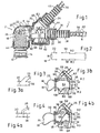
- Fig.1
- eine vergrößerte Seitenansicht eines erfindungsgemäßen Leitungsverbinders mit einem Endbereich einer angeschlossenen Fluidleitung, wobei die erfindungsgemäße Kapselung geöffnet in Form nur einer von zwei Gehäusehälften dargestellt ist,
- Fig. 2
- ein schematisches Ersatzschaltbild von elektrischen Heizmitteln des Fluidverbinders und der Fluidleitung,
- Fig. 3 u. 4
- verschiedene Verschaltungsvarianten der Heizmittel, wobei in
Fig. 3a und 4a jeweils ein schematisches Schaltbild und in denFig. 3b und 4b jeweils der Verbinder im Bereich der elektrischen Verbindungen veranschaulicht ist, - Fig. 5
- eine gesonderte Ansicht auf die Innenseite der Gehäusehälfte zu
Fig. 1 , - Fig. 6
- eine Ansicht der Gehäusehälfte in Pfeilrichtung VI gemäß
Fig. 5 , - Fig. 7
- eine Ansicht auf die Außenseite der Gehäusehälfte in Pfeilrichtung VII gemäß
Fig. 6 , - Fig. 8
- eine Seitenansicht auf eine alternative Ausführungsform einer erfindungsgemäßen Kapselung in Form eines mehrteiligen Außengehäuses,
- Fig. 9
- eine gesonderte Perspektivansicht eines Abzweiggehäuses zur Ausführung gemäß
Fig. 8 in einem geöffneten Zustand, - Fig. 10
- eine Darstellung analog zu
Fig. 1 einer alternativen Ausführungsform, - Fig. 11
- eine zweite Gehäusehälfte zur Ausführung nach
Fig. 10 , - Fig. 12
- eine Perspektivansicht einer konfektionierten Medienleitung, die zum Teil der Ausführung gemäß
Fig. 8 entspricht, - Fig. 13
- eine Seitenansicht einer konfektionierten Medienleitung in einer besonderen Ausgestaltung mit teilweise aufgeschnittener Leitungs-Umhüllung,
- Fig. 14
- eine Ausschnittsvergrößerung des Bereiches XIV in
Fig. 13 , - Fig. 15
- ein elektrisches Ersatzschaltbild zur Ausführung gemäß
Fig. 13 , - Fig. 16
- eine Seitenansicht einer besonderen Ausgestaltung des erfindungsgemäßen Leitungsverbinders mit einem separaten, aufgerasteten Abzweigteil,
- Fig. 17
- einen Längsschnitt des Leitungsverbinders gemäß
Fig. 16 , - Fig. 18
- eine Ansicht wie in
Fig. 16 , jedoch in einem alternativen Montagezustand des Abzweigteils, - Fig. 19
- eine Perspektivansicht einer alternativen Ausführungsform des Leitungsverbinders,
- Fig. 20
- eine gegenüber
Fig. 19 vergrößerte Seitenansicht dieses Leitungsverbinders, - Fig. 21
- eine Ansicht in Pfeilrichtung XXI gemäß
Fig. 20 , - Fig. 22
- eine Perspektivansicht einer ersten Ausführungsform des Abzweigteils für die Ausführung des Leitungsverbinders gemäß
Fig. 19 bis 21 , - Fig. 23
- eine Perspektivansicht des Abzweigteils gemäß
Fig. 22 in einem geöffneten Zustand eines Aufnahmeabschnittes für eine Leiterhülle, - Fig. 24
- eine Perspektivansicht einer zweiten Ausführungsform des Abzweigteils für die Ausführung des Leitungsverbinders gemäß
Fig. 16 ,bis 18 - Fig. 25
- eine Darstellung des Abzweigteils gemäß
Fig. 24 in einem Zustand analog zuFig. 23 , - Fig. 26
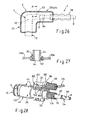
- eine Skizze zur Erläuterung einer alternativen Ausführungsform des Leitungsverbinders in einem Längsschnitt,
- Fig. 27
- einen vergrößerten Teilschnitt in der Ebene A-A gemäß
Fig. 26 in einem mit dem zugehörigen Abzweigteil verbundenen Zustand der Kapselung und - Fig. 28
- eine weitere Ausführungsvariante in einer Darstellung ähnlich
Fig. 19 .
- Fig.1
- an enlarged side view of a line connector according to the invention with an end portion of a connected fluid line, wherein the encapsulation according to the invention is shown in the form of only one of two housing halves open,
- Fig. 2
- a schematic equivalent circuit diagram of electrical heating means of the fluid connector and the fluid line,
- Fig. 3 u. 4
- various Verschaltungsvarianten the heating means, wherein in
Fig. 3a and 4a each a schematic diagram and in theFig. 3b and 4b each connector is illustrated in the field of electrical connections, - Fig. 5
- a separate view of the inside of the housing half
Fig. 1 . - Fig. 6
- a view of the housing half in the direction of arrow VI according to
Fig. 5 . - Fig. 7
- a view of the outside of the housing half in the direction of arrow VII according to
Fig. 6 . - Fig. 8
- a side view of an alternative embodiment of an encapsulation according to the invention in the form of a multi-part outer casing,
- Fig. 9
- a separate perspective view of a branch housing for execution according to
Fig. 8 in an open state, - Fig. 10
- a representation analogous to
Fig. 1 an alternative embodiment, - Fig. 11
- a second housing half for execution
Fig. 10 . - Fig. 12
- a perspective view of a ready-made media line, the part of the embodiment according to
Fig. 8 corresponds, - Fig. 13
- a side view of a prefabricated media line in a particular embodiment with partially cut line enclosure,
- Fig. 14
- an enlarged detail of the area XIV in
Fig. 13 . - Fig. 15
- an electrical equivalent circuit diagram for execution according to
Fig. 13 . - Fig. 16
- a side view of a particular embodiment of the line connector according to the invention with a separate, ratcheted branch part,
- Fig. 17
- a longitudinal section of the line connector according to
Fig. 16 . - Fig. 18
- a view like in
Fig. 16 but in an alternative mounting state of the branch part, - Fig. 19
- a perspective view of an alternative embodiment of the line connector,
- Fig. 20
- one opposite
Fig. 19 enlarged side view of this line connector, - Fig. 21
- a view in the direction of arrow XXI according to
Fig. 20 . - Fig. 22
- a perspective view of a first embodiment of the branch part for the execution of the line connector according to
Fig. 19 to 21 . - Fig. 23
- a perspective view of the branch part according to
Fig. 22 in an opened state of a receiving portion for a conductor cover, - Fig. 24
- a perspective view of a second embodiment of the branch part for the execution of the line connector according to
Fig. 16 to 18 . - Fig. 25
- a representation of the branch part according to
Fig. 24 in a state analogous toFig. 23 . - Fig. 26
- a sketch for explaining an alternative embodiment of the line connector in a longitudinal section,
- Fig. 27
- an enlarged partial section in the plane AA according to
Fig. 26 in a state associated with the associated branch part of the encapsulation and - Fig. 28
- another embodiment in a representation similar
Fig. 19 ,
In den verschiedenen Figuren der Zeichnung sind gleiche Teile stets mit den gleichen Bezugszeichen versehen.In the various figures of the drawing, like parts are always provided with the same reference numerals.
In
Wie sich aus
Der erste Anschlussabschnitt 6 ist bevorzugt als Aufnahme zum Einstecken des Leitungsendes 8a ausgebildet (s. insbesondere
Bereichsweise, und zwar insbesondere zumindest im Bereich des Übergangsabschnittes 10, weist der Fluidverbinder 4 elektrische Heizmittel 18 auf. Diese Heizmittel 18 umschließen zweckmäßigerweise den Fluidkanal 16 zumindest teilweise und sind dazu von mindestens einem über den Außenumfang des Fluidverbinders 4 verlaufenden Heizleiter 20 gebildet.In regions, and in particular at least in the region of the
Erfindungsgemäß weist der Leitungsverbinder 2 eine den Fluidverbinder 4 zumindest im Bereich der Heizmittel 18 umschließende Kapselung 22 auf. Diese Kapselung 22 weist ihrerseits einen rohrstückförmigen Abzweig 24 für elektrische Versorgungsleiter 26 für die Heizmittel 18 auf.According to the invention, the
Erfindungsgemäß ist die Kapselung 22 auch zum Umschließen eines Endbereiches der an dem Anschlussabschnitt 6 angeschlossenen Fluidleitung 8 und eines Endbereiches einer rohrförmigen Umhüllung 28 der Fluidleitung 8 ausgebildet. Mit Vorteil kann die Umhüllung 28 insbesondere formschlüssig innerhalb der Kapselung 22 fixiert sein. Dazu weist die Kapselung 22 einen Rohransatz 30 mit inneren Umfangsrippen 32 auf, die radial in umfängliche Rillen 34 der insbesondere von einem Wellrohr (parallel gewelltes Schutzrohr insbesondere aus Kunststoff) gebildeten Umhüllung 20 eingreifen.According to the invention, the
In den Ausführungen gemäß
In der alternativen Ausführung gemäß
Die zweiteilige Ausführung gemäß
Gemäß
Auch das Verbindergehäuse 36 bzw. 38 besteht mit Vorteil aus zwei zu einer Teilungsebene im Wesentlichen symmetrischen Gehäuse-Halbschalen a und b, die ebenfalls bevorzugt miteinander über Rastmittel 44 verrastbar sind. Die Gehäuse-Halbschalen 36a, b bzw. 38a, b sind in den dargestellten Beispielen als getrennte, vorzugsweise zumindest annähernd identische Formteile ausgebildet. Alternativ kann aber auch analog zu
Optional können die Gehäuse-Halbschalen im Bereich ihrer im geschlossenen Zustand aneinander liegenden Anlageränder bestimmte Dichtmittel, wie z. B. ineinander greifende Dichtkonturen (z. B. nach Art einer Nut-/Federverbindung) oder angeformte Weichdichtungen (Elastomerbeschichtung) aufweisen.Optionally, the housing half-shells in the region of their contiguous in the closed state investment edge certain sealing means, such as. B. interlocking sealing contours (eg., In the manner of a tongue and groove connection) or molded soft seals (elastomer coating) have.
In weiterer vorteilhafter Ausgestaltung der Erfindung ist der Abzweig 24 zur formschlüssigen Aufnahme eines Endbereiches einer rohrförmigen Leiterhülle 46 für die Versorgungsleiter 26 ausgebildet. Analog zu der Umhüllung 28 handelt es sich auch bei der Leiterhülle 46 vorzugsweise um ein Wellrohr aus Kunststoff. Deshalb weist auch der Abzweig 24 eine innere Eingriffskontur mit mindestens einer radial nach innen vorspringenden Umfangsrippe 48 auf (siehe auch
Bei der Ausführungsvariante gemäß
In bevorzugter Ausgestaltung weist nämlich die Fluidleitung 8 ebenfalls elektrische Heizmittel 54 auf, die insbesondere von mindestens einem schraubenlinienförmig über den Leitungsumfang verlaufenden Heizleiter 56 gebildet sind. Dazu wird insbesondere auf
Der Abzweig 24 kann bezüglich seiner Abzweigachse mit einer Anschlussachse der Fluidleitung 8 einen praktisch beliebigen Winkel α einschließen, der bevorzugt aber im Bereich von 20° bis 160° liegt. In den dargestellten Beispielen handelt es sich um einen spitzwinkligen Y-Abzweig, es kann aber auch ein etwa rechtwinkliger T-Abzweig vorgesehen sein (siehe
Die Enden der Heizleiter 20, 56 werden insbesondere im Übergangsbereich zwischen dem Fluidverbinder 4 und der Fluidleitung 8 miteinander und/oder mit den äußeren Versorgungsleitern 26 über elektrische Verbindungen 58 verbunden (verschaltet). Zu diesen Verbindungen 58 wird auf die in den
In vorteilhafter Ausgestaltung sind/ist der Fluidverbinder 4 und/oder die angeschossene Fiuidleitung 8 bereichsweise unter Einschluss der elektrischen Verbindungen 58 der Heizmittel 18, 54 mit einer Kunststoff-Formmasse, insbesondere mit einem thermoplastischen Formteilwerkstoff, z. B. auf PA-Basis, umgeben (umformt, z. B. umspritzt oder vergossen). Dieses Anformen mit Kunststoff erfolgt insbesondere im Übergangsbereich zwischen dem Anschlussabschnitt 6 des Fluidverbinders 4 und der angeschlossenen Fluidleitung 8. Hierdurch entsteht eine vergossene Baueinheit aus dem Fluidverbinder 4 und der Fluidleitung 8 mit deren Heizmitteln 18, 54, wobei die erforderlichen elektrischen Verbindungen 58 in einem angeformten Ansatzteil 60 eingebettet und dadurch vor jeglichen mechanischen und sonstigen Einflüssen geschützt sowie auch gegeneinander elektrisch isoliert sind. Dabei sind das Ansatzteil 60 bezüglich seiner Außenkontur und die Kapselung 22 bezüglich ihrer Innenkontur so aneinander angepasst, dass das Ansatzteil 60 formschlüssig in der Kapselung 22 untergebracht ist. Gemäß
Im Übrigen besteht das Ansatzteil 60 aus einem etwa zylindrischen Basisabschnitt 64, der den Übergangsbereich zwischen Anschlussabschnitt 6 und Fluidleitung 8 umschließt. Weiterhin kann das Ansatzteil 60 flansch- oder flügelartige, diametral in einer Ebene gegenüberliegende Ansätze 66 aufweisen, die von dem Basisabschnitt 64 ausgehen. Die Ansätze 66 bewirken eine effektive Verdrehsicherung des Ansatzteils 60 innerhalb der Kapselung 22 und können auch zur Unterbringung der elektrischen Verbindungen 58 an beliebigen Stellen benutzt werden (vgl.
Die Bildung des Ansatzteils 60 erfolgt in einem geeigneten Formwerkzeug. Dieses Werkzeug kann beispielsweise stiftförmige Positionierungselemente für die elektrischen Verbindungen 58 aufweisen, um diese während des Formvorgangs so zu positionieren, dass sie optimal in den Kunststoff eingebettet werden. Zudem sollen auch Berührungen der metallischen, abisolierten Enden der Heizleiter vermieden werden. Durch diese Positionieransätze entstehen nach dem Formvorgang gemäß
Nach Montage der Kapselung 22 wird vorzugsweise ein dann noch verbleibender Freiraum innerhalb der Kapselung 22 zumindest teilweise mit Kunststoff vergossen. Dazu kann die Kapselung mindestens eine Öffnung 70 (vgl.
Wie sich noch aus
An dieser Stelle sollen anhand der
Gemäß
Bei der in
Was noch die Ausführung der Medienleitung 1 gemäß
In den Ausführungsformen gemäß
Das Abzweigteil 80 ist bevorzugt lösbar (trennbar) mit dem Verbindergehäuse 36 verbunden oder verbindbar.The
In den Ausführungen gemäß
Bei der alternativen Ausführung gemäß
In allen Ausführungen kann die Öffnung 82 des Verbindergehäuses 36 vorgefertigt sein. Bevorzugt ist aber die Öffnung 82 durch Entfernen von mindestens einem ursprünglich vorhandenen Gehäusebereich herstellbar. Es kann sich um Wandungsabschnitte der Gehäuseteile 36a, 36b handeln, die über Sollbruchstellen herausbrechbar sind.In all embodiments, the
In weiterer vorteilhafter Ausgestaltung weist das Abzweigteil 80 zur formschlüssigen Aufnahme des Endbereiches der rohrförmigen Leiterhülle 46 für die Versorgungsleiter 26 einen rohrstückförmigen Aufnahmeabschnitt 96 für die Leiterhülle 46 auf. Wie sich insbesondere aus
Im Falle eines spitz- oder stumpfwinkligen oder auch parallelen Abzweigs ist die separate Ausgestaltung des Abzweigteils 80 von besonderem Vorteil, weil gemäß
Abschließend sei nochmals erwähnt, dass sich die Erfindung auch auf die gesamte konfektionierte Medienleitung 1 beispielsweise in einer Ausführung gemäß
Claims (16)
- A line connector (2) for media lines (1), composed of a fluid connector (4) having at least one attachment section (6) for attachment connection to a fluid line (8) and having a transition section (10) which adjoins the attachment section (6) and has an inner fluid duct (16), with electrical heating means (18) being provided at least in the region, of the transition section (10) which heating means (18) at least partially surround the fluid duct (16) and are formed by at least one heat conductor (20) which runs over the outer circumference of the fluid connector (4), wherein a casing (22) for surrounding an end region of the fluid line (8) attached to the attachment section (6) and an end region of a tubular sheathing of the fluid line (8) and having a branch (24) for electrical supply cables (26) for the heating means (18) is provided, wherein the casing (22) surrounds the heating means (18) present in the region of the transition section (10), characterized in that the heat conductor (20) spirally surrounds the transition section (10) and the casing (22) encloses the heat conductor (20), wherein an air gap is formed within the casing (22).
- The line connector as claimed in claim 1, characterized in that the casing (22) is composed of a connector housing (36) which has the branch (24).
- The line connector as claimed in claim 2,
characterized in that the connector housing (36) is formed, in the region of a leadthrough for the fluid line (8), to hold the end region of the sheathing (28) of the fluid line (8) in a positively locking fashion. - The line connector as claimed in claim 1,
characterized in that the casing (22) is composed of a connector housing (38) and an additional branch housing (40) which has the branch (24). - The line connector as claimed in claim 4,
characterized in that the branch housing (40) is composed of a tubular passage section for the fluid line (8) and of the branch (24) which branches off from the passage section, with the passage section being connected or connectable at one end directly to the connector housing (38) and preferably being designed at the other end to hold the end region of the sheathing (28) of the fluid line (8) in a positively locking fashion. - The line connector as claimed in one of claims 2 to 5,
characterized in that the connector housing (36; 38) is composed of two housing half shells (a, b) which are substantially symmetrical in relation to a parting plane and which can preferably be latched to one another by latching means (44). - The line connector as claimed in one of claims 4 to 6,
characterized in that the branch housing (40) is composed of two housing half shells (40a, 40b) which are substantially symmetrical with respect to a parting plane and which can preferably be latched to one another by latching means (42). - The line connector as claimed in claim 6 or 7,
characterized in that the housing half shells (36a, 36b; 38a, 38b; 40a, 40b) are formed as separate, preferably identical molded parts or, as a single-piece molded part, are connected to one another in a hinged fashion in particular by means of at least one film hinge (40c). - The line connector as claimed in one of claims 1 to 8,
characterized in that the branch (24) is designed to hold an end region of a tubular cable sheath (46) for the supply cables (26) in a positively locking fashion. - The line connector as claimed in one of claims 1 to 9,
characterized in that the branch (24) has an electrical connection element (50), in particular in the form of a plug connection, for external supply cables, with the connection element (50) being connected within the casing (22) to the heating means (18) of the fluid connector (4) and/or if appropriate to heating means (54) of an attached fluid line (8). - The line connector as claimed in one of claims 1 to 10,
characterized in that the fluid line (8) has electrical heating means (54) which are formed in particular by at least one heat conductor (56) which runs in a helical fashion over the circumference of the line. - The line connector as claimed in one of claims 1 to 11,
characterized in that the branch (24), with regard to its branch axis, encloses an angle (α) in the range from 20° to 160° with a fluid line attachment axis or is aligned approximately parallel to the attachment axis. - The line connector as claimed in one of claims 1 to 12,
characterized in that the fluid connector (4) and/or an attached fluid line (8) are/is encased with a plastic molding compound with the encompassment of electrical connections (58) of the heating means (18, 54). - The line connector as claimed in one of claims 1 to 13,
characterized in that the branch (24) is designed as a separate branch part (80) which is or can be connected to the casing (22). - The line connector as claimed in claim 14,
characterized in that the branch part (80) is or can be connected by latching means (84) to the connector housing (36) in the region of an opening (82) of said connector housing (36), or is or can be inserted in a positively locking fashion between two housing parts (36a, 36b) in the region of an opening (82), which is situated in a parting plane, of the connector housing (36). - An assembled media line (1) composed of at least one line connector (2) as claimed in one of claims 1 to 15 and of an attached fluid line (8) and of a line sheathing (28) an having two line connectors (2) connected at the end side,
characterized in that at least one, preferably at least two electrical cables (26') run within the sheathing (28), in particular in a free space (76) between the fluid line (8) and the sheathing (28), which electrical cables (26') connect connectors for external supply cables in the region of the branches (24) of the line connectors (2) to one another.
Priority Applications (1)
| Application Number | Priority Date | Filing Date | Title |
|---|---|---|---|
| PL08865799T PL2222995T3 (en) | 2007-12-21 | 2008-12-10 | Line connector for media lines and ready-made media line with at least one such line connector |
Applications Claiming Priority (3)
| Application Number | Priority Date | Filing Date | Title |
|---|---|---|---|
| DE202007018086U DE202007018086U1 (en) | 2007-12-21 | 2007-12-21 | Cable connector for media cables and ready-made media cable with at least one such cable connector |
| DE202008004954U DE202008004954U1 (en) | 2008-04-09 | 2008-04-09 | Cable connector for media cables and ready-made media cable with at least one such cable connector |
| PCT/EP2008/067159 WO2009080501A1 (en) | 2007-12-21 | 2008-12-10 | Line connector for media lines and ready-made media line with at least one such line connector |
Publications (2)
| Publication Number | Publication Date |
|---|---|
| EP2222995A1 EP2222995A1 (en) | 2010-09-01 |
| EP2222995B1 true EP2222995B1 (en) | 2014-12-10 |
Family
ID=40456132
Family Applications (1)
| Application Number | Title | Priority Date | Filing Date |
|---|---|---|---|
| EP08865799.4A Active EP2222995B1 (en) | 2007-12-21 | 2008-12-10 | Line connector for media lines and ready-made media line with at least one such line connector |
Country Status (5)
| Country | Link |
|---|---|
| US (1) | US9890889B2 (en) |
| EP (1) | EP2222995B1 (en) |
| ES (1) | ES2529573T3 (en) |
| PL (1) | PL2222995T3 (en) |
| WO (1) | WO2009080501A1 (en) |
Cited By (1)
| Publication number | Priority date | Publication date | Assignee | Title |
|---|---|---|---|---|
| CN104776285A (en) * | 2015-03-30 | 2015-07-15 | 苏州福润机械有限公司 | Curve pipe fitting |
Families Citing this family (25)
| Publication number | Priority date | Publication date | Assignee | Title |
|---|---|---|---|---|
| PL2137449T5 (en) * | 2007-04-26 | 2019-03-29 | Voss Automotive Gmbh | Line connector for media lines |
| US9651185B2 (en) | 2008-03-19 | 2017-05-16 | Voss Automotive Gmbh | Line connector for media lines |
| US9505164B2 (en) | 2009-12-30 | 2016-11-29 | Schauenburg Technology Se | Tapered helically reinforced hose and its manufacture |
| DE102008022663B4 (en) | 2008-05-07 | 2012-10-31 | Schauenburg Hose Technology Gmbh | Stretch hose |
| US9964238B2 (en) | 2009-01-15 | 2018-05-08 | Globalmed, Inc. | Stretch hose and hose production method |
| DE202009012431U1 (en) * | 2009-09-15 | 2011-02-10 | A. Raymond Et Cie S.C.S. | Connecting device for a windshield wiper system |
| DE102009044404A1 (en) * | 2009-11-03 | 2011-05-05 | Contitech Techno-Chemie Gmbh | System for connecting hose lines |
| DE102010032189A1 (en) | 2010-07-23 | 2012-01-26 | Voss Automotive Gmbh | Heatable media line and method for its production |
| DE102010035028B4 (en) * | 2010-08-20 | 2013-07-18 | Voss Automotive Gmbh | Heated cable connectors with insulation and / or protective cover and heatable media cable with at least one cable connector with insulation and / or protective cover |
| DE102010051550A1 (en) | 2010-11-18 | 2012-05-24 | Voss Automotive Gmbh | Assembled electrically heatable media line and method for producing such a media line |
| DE102010055520B4 (en) * | 2010-12-22 | 2023-10-05 | Voss Automotive Gmbh | Assembled media line and use in an SCR catalytic converter system |
| DE102011120357A1 (en) * | 2011-12-07 | 2013-06-13 | Voss Automotive Gmbh | Prefabricated heatable media line with a media line with at least two arranged on the outside heating elements and method for their preparation |
| DE102011120356A1 (en) | 2011-12-07 | 2013-06-13 | Voss Automotive Gmbh | Prefabricated media line and method for assembling a media line with internal heating elements |
| JP6131277B2 (en) | 2012-02-28 | 2017-05-17 | ノーマ・ユー・エス・ホールディング・リミテッド・ライアビリティ・カンパニーNorma U. S. Holding Llc | Automotive selective contact reduction (SCR) system sensor holder and assembly |
| DE102012018069A1 (en) | 2012-09-13 | 2014-03-13 | Eugen Forschner Gmbh | Device for connecting fluid-carrying lines |
| DE102014102357A1 (en) | 2014-02-24 | 2015-08-27 | Norma Germany Gmbh | Heatable fluid line |
| DE102014005818A1 (en) * | 2014-04-24 | 2015-10-29 | Voss Automotive Gmbh | Connecting device, method for producing a connecting device, measuring device and method for producing a measuring device |
| US20170023163A1 (en) * | 2015-07-20 | 2017-01-26 | Norma U.S. Holding Llc | Heated Connector Assembly |
| EP3276243B2 (en) * | 2016-07-28 | 2021-11-10 | TI Automotive (Fuldabrück) GmbH | Fluid line for motor vehicle |
| DE202016107103U1 (en) * | 2016-12-19 | 2018-03-21 | Voss Automotive Gmbh | Wiring harness for tempered leadership of a reducing agent for the exhaust aftertreatment of an internal combustion engine |
| US20180214658A1 (en) | 2017-01-30 | 2018-08-02 | Globalmed Inc. | Heated respiratory hose connection |
| DE202018100115U1 (en) * | 2018-01-10 | 2018-02-27 | Voss Automotive Gmbh | Assembled fluid line |
| JP6708681B2 (en) * | 2018-03-12 | 2020-06-10 | トヨタ自動車株式会社 | Protector |
| IT201900007016A1 (en) * | 2019-05-20 | 2020-11-20 | Hutchinson Srl | Hydraulic and electrical connection system for a plurality of ducts configured to be crossed by an electrically heatable fluid. |
| FR3106390B1 (en) * | 2020-01-20 | 2021-12-10 | Hutchinson | HEATED SHELL FOR THREE-WAY CONNECTION |
Citations (1)
| Publication number | Priority date | Publication date | Assignee | Title |
|---|---|---|---|---|
| EP0379635A1 (en) * | 1989-01-26 | 1990-08-01 | REHAU AG + Co | Thermally insulated connection or distribution piece for heatable hoses |
Family Cites Families (61)
| Publication number | Priority date | Publication date | Assignee | Title |
|---|---|---|---|---|
| US1809714A (en) * | 1929-04-01 | 1931-06-09 | Mathews Carl Raymond | Heated water hose for filling stations |
| US2723108A (en) * | 1951-02-24 | 1955-11-08 | Diamond Alkali Co | Valve |
| FR1065308A (en) | 1952-06-26 | 1954-05-24 | Advanced pipeline for multiple fluids | |
| US2793280A (en) * | 1954-10-06 | 1957-05-21 | Waterbury Pressed Metal Co | Electrically heated liquid connection unit |
| US3378673A (en) * | 1965-10-18 | 1968-04-16 | Thomas O. Hopper | Electrically heated hose assembly |
| US3789188A (en) * | 1972-02-14 | 1974-01-29 | Fmc Corp | Insulated pipe line for heated materials |
| US3968346A (en) * | 1973-06-01 | 1976-07-06 | Cooksley Ralph D | Method and apparatus for electrically heating a fluid |
| US3932727A (en) | 1973-12-11 | 1976-01-13 | Cecil Wayne True | Electrically heated riser pipe for a fluid supply system |
| US3986732A (en) | 1975-03-24 | 1976-10-19 | The Goodyear Tire & Rubber Company | Dual concentric vapor recovery fuel hose and end fitting therefor |
| US4435005A (en) | 1975-09-10 | 1984-03-06 | Berger Industries, Inc. | Joint for conduit with single threaded end |
| US4195865A (en) | 1976-11-03 | 1980-04-01 | Martin Charles F | Apparatus for connecting tubular members |
| US4213433A (en) * | 1977-10-31 | 1980-07-22 | Day John C | Liquid fuel to gas converter for engines |
| DE2752374A1 (en) | 1977-11-24 | 1979-05-31 | Messerschmitt Boelkow Blohm | PIPE COUPLING FOR FORCE COMPENSATING PRESSURE PEAK DAMPING |
| US4161647A (en) * | 1977-11-29 | 1979-07-17 | Henri Carbonnel | Electrically heated spigot for connecting an electromagnetic supplying pump to the inlet of a low pressure casting mould |
| US4553023A (en) * | 1981-11-27 | 1985-11-12 | Nordson Corporation | Thermally insulated electrically heated hose for transmitting hot liquids |
| US4455474A (en) * | 1981-11-27 | 1984-06-19 | Nordson Corporation | Thermally insulated electrically heated hose for transmitting hot liquids |
| GB2173274B (en) * | 1985-04-04 | 1989-02-01 | Boc Group Plc | Improvements in inhalation apparatus |
| DE3536751A1 (en) | 1985-10-15 | 1987-04-16 | Alligator Ventilfab Gmbh | HEATING DEVICE FOR WASHING LIQUID IN WINDOW WASHER SYSTEMS OF VEHICLES |
| DE8704903U1 (en) | 1987-04-02 | 1987-05-27 | Rehau Ag + Co, 8673 Rehau, De | |
| US4993607A (en) * | 1989-07-10 | 1991-02-19 | General Electric Company | Transfer tube with in situ heater |
| US4995644A (en) * | 1989-08-28 | 1991-02-26 | The United States Of America As Represented By The Secretary Of The Army | Load balanced coolant fitting |
| US5239615A (en) * | 1990-09-17 | 1993-08-24 | Pacific Rainier Roofing, Inc. | System for transporting highly viscous waterproofing membrane |
| US5544275A (en) | 1993-03-17 | 1996-08-06 | Applied Materials, Inc. | Electrically heated fluid carrying conduit having integrated heating elements and electrical conductors |
| JPH08152082A (en) | 1994-11-28 | 1996-06-11 | Togo Seisakusho:Kk | Pipe connection device |
| DE19510193A1 (en) | 1995-03-21 | 1996-09-26 | Voss Armaturen | Connection device for pipes |
| EP0764810B1 (en) | 1995-09-20 | 1999-08-18 | Luciano Scarzella | Insulation and/or heating and/or colling system with prefabricated elements separated from the pipes and components of the plants through which process fluids are flowing |
| JPH10306889A (en) | 1997-05-02 | 1998-11-17 | Nok Corp | Piping coupling |
| DE19818649A1 (en) | 1998-04-25 | 1999-10-28 | Behr Gmbh & Co | Vehicle air-conditioning system |
| DE29807763U1 (en) | 1998-04-29 | 1999-09-09 | Voss Armaturen | Connection device for quick and detachable connection of pipes |
| JP2000065266A (en) | 1998-08-19 | 2000-03-03 | Toyota Motor Corp | Spherical pipe fitting |
| JP3324550B2 (en) | 1999-03-17 | 2002-09-17 | 株式会社栗本鐵工所 | Seismic propulsion method and pipe fittings |
| US6550815B2 (en) | 2001-08-14 | 2003-04-22 | Itt Manufacturing Enterprises, Inc. | Coaxial quick connector |
| MXPA04001920A (en) | 2001-08-30 | 2004-07-23 | Cooper Technology Services Llc | Heated pcv valve and hose assemblies. |
| DE20115436U1 (en) | 2001-09-19 | 2003-02-20 | Voss Automotive Gmbh | Connection device for fluid lines |
| US6617556B1 (en) | 2002-04-18 | 2003-09-09 | Conocophillips Company | Method and apparatus for heating a submarine pipeline |
| DE20214847U1 (en) | 2002-09-24 | 2004-02-19 | Voss Automotive Gmbh | Connection device for pipes |
| DE10326894B3 (en) | 2003-06-14 | 2004-09-30 | Rasmussen Gmbh | Heating arrangement with electrical heat source for heating fluid in motor vehicle fluid line has heat conducting device connected to clamp for connecting heat conducting device to fluid line |
| KR100574744B1 (en) | 2003-06-27 | 2006-04-27 | 김수근 | Pipe moving regulation joint device |
| DE10340467B4 (en) * | 2003-09-03 | 2012-10-04 | Man Truck & Bus Ag | Device for guiding a flowable medium |
| EP1684923A4 (en) | 2003-10-20 | 2008-11-12 | Internat Resistive Company | Resistive film on aluminum tube |
| DE10362140C5 (en) | 2003-12-29 | 2015-10-08 | Cummins Ltd. | Freezer-compatible exhaust aftertreatment device for a motor vehicle |
| DE102004021667A1 (en) | 2004-05-03 | 2005-11-24 | Conti Tech Techno-Chemie Gmbh | Hose connector system for a heatable hose comprises a pipe section which forms a part of a pipe bend accommodating at the hose joint the free end sections of the heater wire |
| SE0401557D0 (en) | 2004-06-15 | 2004-06-15 | Volvo Lastvagnar Ab | Electric heating coupler and enclosed liquid hose with electrically heated coupler |
| SE529158C2 (en) | 2005-02-23 | 2007-05-15 | Scania Cv Abp | Methods and apparatus for supplying additive for exhaust gas purification and conduction |
| GB0503891D0 (en) | 2005-02-25 | 2005-04-06 | Allen Group Ltd | Electrically-heated pipes |
| DE202005004602U1 (en) | 2005-03-18 | 2005-07-14 | Eichenauer Heizelemente Gmbh & Co. Kg | Heated pipe for liquids comprises an plastic inner hose, a middle layer of an electrically conductive polymer with embedded wires, and an outer insulating layer |
| EP1710484B1 (en) | 2005-04-05 | 2009-06-17 | DBK David + Baader GmbH | Electrical heater for a fluid in a flexible hose |
| DE202006003590U1 (en) | 2005-04-14 | 2006-06-01 | Schlemmer Gmbh | Heatable corrugated hose for motor vehicles has crests and gaps to produce sequence of gaps, which is extended spirally over the length of corrugated hose forming a corrugation, within which heating element can be inserted |
| DE102006034697A1 (en) | 2005-08-20 | 2007-02-22 | Luk Lamellen Und Kupplungsbau Beteiligungs Kg | Plastic line, especially coupling line, has angled hydraulic plug welded onto one end of plastic line with O-ring made of self-lubricating material; plastic housing of hydraulic element is welded directly onto one end of plastic line |
| DE202005013691U1 (en) | 2005-08-30 | 2007-01-11 | Voss Automotive Gmbh | Connection device for media conduits e.g. tubes or hose lines for gases or other fluids, has deformation zone to space apart catching extensions of spring arms of inner insertion piece from contamination seal seated on free ends of arms |
| EP1931906A1 (en) | 2005-09-16 | 2008-06-18 | Dayco Fluid Technologies S.p.A. | Pipe fitting for a heatable piping of a scr system |
| US20070073286A1 (en) * | 2005-09-29 | 2007-03-29 | Dorin Panescu | Method and apparatus for an ocular procedure |
| DE102005050867A1 (en) | 2005-10-24 | 2007-04-26 | Dbk David + Baader Gmbh | Heatable connector |
| SE529417C2 (en) | 2005-12-22 | 2007-08-07 | Volvo Lastvagnar Ab | Wiring harness for a vehicle |
| DE102006006211B3 (en) | 2006-02-09 | 2007-09-20 | Rehau Ag + Co | Assembly for conducting and tempering a urea-water solution and method for the production thereof |
| WO2007125572A1 (en) | 2006-04-26 | 2007-11-08 | Nissan Diesel Motor Co., Ltd. | Heater component for pipe joint |
| US7449661B1 (en) * | 2006-11-03 | 2008-11-11 | Bench Steven D | In-pipe heat trace system |
| PL1985908T5 (en) * | 2007-04-26 | 2018-12-31 | Voss Automotive Gmbh | Circuit connector for fluid transfers |
| DE202007010502U1 (en) | 2007-07-26 | 2008-11-27 | Voss Automotive Gmbh | Ready-made media line |
| DE202007010865U1 (en) * | 2007-08-03 | 2007-10-11 | Türk & Hillinger GmbH | Electric heating cartridge |
| DE202007018089U1 (en) * | 2007-12-21 | 2009-05-07 | Voss Automotive Gmbh | Heatable media line |
-
2008
- 2008-12-10 EP EP08865799.4A patent/EP2222995B1/en active Active
- 2008-12-10 WO PCT/EP2008/067159 patent/WO2009080501A1/en active Application Filing
- 2008-12-10 ES ES08865799.4T patent/ES2529573T3/en active Active
- 2008-12-10 US US12/808,588 patent/US9890889B2/en active Active
- 2008-12-10 PL PL08865799T patent/PL2222995T3/en unknown
Patent Citations (1)
| Publication number | Priority date | Publication date | Assignee | Title |
|---|---|---|---|---|
| EP0379635A1 (en) * | 1989-01-26 | 1990-08-01 | REHAU AG + Co | Thermally insulated connection or distribution piece for heatable hoses |
Cited By (1)
| Publication number | Priority date | Publication date | Assignee | Title |
|---|---|---|---|---|
| CN104776285A (en) * | 2015-03-30 | 2015-07-15 | 苏州福润机械有限公司 | Curve pipe fitting |
Also Published As
| Publication number | Publication date |
|---|---|
| US20110006513A1 (en) | 2011-01-13 |
| WO2009080501A1 (en) | 2009-07-02 |
| US9890889B2 (en) | 2018-02-13 |
| EP2222995A1 (en) | 2010-09-01 |
| ES2529573T3 (en) | 2015-02-23 |
| PL2222995T3 (en) | 2015-04-30 |
Similar Documents
| Publication | Publication Date | Title |
|---|---|---|
| EP2222995B1 (en) | Line connector for media lines and ready-made media line with at least one such line connector | |
| EP2220419B1 (en) | Heatable media line | |
| EP2679874B1 (en) | Electrically heatable fluid line with line connector | |
| EP2137449B9 (en) | Line connector for media lines | |
| EP1985908B2 (en) | Circuit connector for fluid transfers | |
| EP2347163B2 (en) | Line connector for media lines | |
| EP2596274B1 (en) | Heatable fluid line and method for its production | |
| DE202007009588U1 (en) | Cable connector for media cables | |
| EP2596275B1 (en) | Heatable fluid line | |
| EP2766651B1 (en) | Assembled media line comprising at least a heatable media line and at least a partially heatable line-connector | |
| DE202011106751U1 (en) | At least partially heatable cable connector for a heatable media line and ready-made media line with such a cable connector | |
| EP2788692B1 (en) | Assembled heatable media line comprising a media line having at least two heating elements arranged on the exterior thereof, and method for the production thereof | |
| EP2420715B2 (en) | Insulation and/or protective covering for heatable connectors | |
| DE202007018086U1 (en) | Cable connector for media cables and ready-made media cable with at least one such cable connector | |
| DE202008004954U1 (en) | Cable connector for media cables and ready-made media cable with at least one such cable connector | |
| EP3769002A1 (en) | Heated media line with mounting part | |
| EP3737885B1 (en) | Preassembled fluid line | |
| DE102018107004A1 (en) | Heated media line with fixing part | |
| DE102011115890A1 (en) | Partially heated line connector for heatable media line of assembled media line, is partially made of thermally conductive material, where heating system or heating elements are assigned outside body of line connector |
Legal Events
| Date | Code | Title | Description |
|---|---|---|---|
| PUAI | Public reference made under article 153(3) epc to a published international application that has entered the european phase |
Free format text: ORIGINAL CODE: 0009012 |
|
| 17P | Request for examination filed |
Effective date: 20100526 |
|
| AK | Designated contracting states |
Kind code of ref document: A1 Designated state(s): AT BE BG CH CY CZ DE DK EE ES FI FR GB GR HR HU IE IS IT LI LT LU LV MC MT NL NO PL PT RO SE SI SK TR |
|
| AX | Request for extension of the european patent |
Extension state: AL BA MK RS |
|
| 17Q | First examination report despatched |
Effective date: 20101125 |
|
| DAX | Request for extension of the european patent (deleted) | ||
| GRAP | Despatch of communication of intention to grant a patent |
Free format text: ORIGINAL CODE: EPIDOSNIGR1 |
|
| RIC1 | Information provided on ipc code assigned before grant |
Ipc: H05B 3/42 20060101ALI20140627BHEP Ipc: F16L 25/01 20060101AFI20140627BHEP Ipc: F16L 53/00 20060101ALI20140627BHEP |
|
| INTG | Intention to grant announced |
Effective date: 20140725 |
|
| GRAS | Grant fee paid |
Free format text: ORIGINAL CODE: EPIDOSNIGR3 |
|
| GRAA | (expected) grant |
Free format text: ORIGINAL CODE: 0009210 |
|
| AK | Designated contracting states |
Kind code of ref document: B1 Designated state(s): AT BE BG CH CY CZ DE DK EE ES FI FR GB GR HR HU IE IS IT LI LT LU LV MC MT NL NO PL PT RO SE SI SK TR |
|
| REG | Reference to a national code |
Ref country code: GB Ref legal event code: FG4D Free format text: NOT ENGLISH |
|
| REG | Reference to a national code |
Ref country code: CH Ref legal event code: EP |
|
| REG | Reference to a national code |
Ref country code: IE Ref legal event code: FG4D Free format text: LANGUAGE OF EP DOCUMENT: GERMAN |
|
| REG | Reference to a national code |
Ref country code: AT Ref legal event code: REF Ref document number: 700836 Country of ref document: AT Kind code of ref document: T Effective date: 20150115 |
|
| REG | Reference to a national code |
Ref country code: DE Ref legal event code: R096 Ref document number: 502008012491 Country of ref document: DE Effective date: 20150122 |
|
| REG | Reference to a national code |
Ref country code: ES Ref legal event code: FG2A Ref document number: 2529573 Country of ref document: ES Kind code of ref document: T3 Effective date: 20150223 |
|
| REG | Reference to a national code |
Ref country code: NL Ref legal event code: VDEP Effective date: 20141210 |
|
| REG | Reference to a national code |
Ref country code: NL Ref legal event code: VDEP Effective date: 20141210 |
|
| PG25 | Lapsed in a contracting state [announced via postgrant information from national office to epo] |
Ref country code: NO Free format text: LAPSE BECAUSE OF FAILURE TO SUBMIT A TRANSLATION OF THE DESCRIPTION OR TO PAY THE FEE WITHIN THE PRESCRIBED TIME-LIMIT Effective date: 20150310 Ref country code: LT Free format text: LAPSE BECAUSE OF FAILURE TO SUBMIT A TRANSLATION OF THE DESCRIPTION OR TO PAY THE FEE WITHIN THE PRESCRIBED TIME-LIMIT Effective date: 20141210 Ref country code: FI Free format text: LAPSE BECAUSE OF FAILURE TO SUBMIT A TRANSLATION OF THE DESCRIPTION OR TO PAY THE FEE WITHIN THE PRESCRIBED TIME-LIMIT Effective date: 20141210 |
|
| REG | Reference to a national code |
Ref country code: PL Ref legal event code: T3 |
|
| REG | Reference to a national code |
Ref country code: LT Ref legal event code: MG4D |
|
| PG25 | Lapsed in a contracting state [announced via postgrant information from national office to epo] |
Ref country code: GR Free format text: LAPSE BECAUSE OF FAILURE TO SUBMIT A TRANSLATION OF THE DESCRIPTION OR TO PAY THE FEE WITHIN THE PRESCRIBED TIME-LIMIT Effective date: 20150311 Ref country code: HR Free format text: LAPSE BECAUSE OF FAILURE TO SUBMIT A TRANSLATION OF THE DESCRIPTION OR TO PAY THE FEE WITHIN THE PRESCRIBED TIME-LIMIT Effective date: 20141210 Ref country code: SE Free format text: LAPSE BECAUSE OF FAILURE TO SUBMIT A TRANSLATION OF THE DESCRIPTION OR TO PAY THE FEE WITHIN THE PRESCRIBED TIME-LIMIT Effective date: 20141210 Ref country code: LV Free format text: LAPSE BECAUSE OF FAILURE TO SUBMIT A TRANSLATION OF THE DESCRIPTION OR TO PAY THE FEE WITHIN THE PRESCRIBED TIME-LIMIT Effective date: 20141210 |
|
| PG25 | Lapsed in a contracting state [announced via postgrant information from national office to epo] |
Ref country code: BE Free format text: LAPSE BECAUSE OF NON-PAYMENT OF DUE FEES Effective date: 20141231 Ref country code: NL Free format text: LAPSE BECAUSE OF FAILURE TO SUBMIT A TRANSLATION OF THE DESCRIPTION OR TO PAY THE FEE WITHIN THE PRESCRIBED TIME-LIMIT Effective date: 20141210 |
|
| PG25 | Lapsed in a contracting state [announced via postgrant information from national office to epo] |
Ref country code: EE Free format text: LAPSE BECAUSE OF FAILURE TO SUBMIT A TRANSLATION OF THE DESCRIPTION OR TO PAY THE FEE WITHIN THE PRESCRIBED TIME-LIMIT Effective date: 20141210 Ref country code: CZ Free format text: LAPSE BECAUSE OF FAILURE TO SUBMIT A TRANSLATION OF THE DESCRIPTION OR TO PAY THE FEE WITHIN THE PRESCRIBED TIME-LIMIT Effective date: 20141210 Ref country code: SK Free format text: LAPSE BECAUSE OF FAILURE TO SUBMIT A TRANSLATION OF THE DESCRIPTION OR TO PAY THE FEE WITHIN THE PRESCRIBED TIME-LIMIT Effective date: 20141210 Ref country code: RO Free format text: LAPSE BECAUSE OF FAILURE TO SUBMIT A TRANSLATION OF THE DESCRIPTION OR TO PAY THE FEE WITHIN THE PRESCRIBED TIME-LIMIT Effective date: 20141210 Ref country code: PT Free format text: LAPSE BECAUSE OF FAILURE TO SUBMIT A TRANSLATION OF THE DESCRIPTION OR TO PAY THE FEE WITHIN THE PRESCRIBED TIME-LIMIT Effective date: 20150410 |
|
| REG | Reference to a national code |
Ref country code: CH Ref legal event code: PL |
|
| PG25 | Lapsed in a contracting state [announced via postgrant information from national office to epo] |
Ref country code: IS Free format text: LAPSE BECAUSE OF FAILURE TO SUBMIT A TRANSLATION OF THE DESCRIPTION OR TO PAY THE FEE WITHIN THE PRESCRIBED TIME-LIMIT Effective date: 20150410 |
|
| REG | Reference to a national code |
Ref country code: DE Ref legal event code: R097 Ref document number: 502008012491 Country of ref document: DE |
|
| REG | Reference to a national code |
Ref country code: IE Ref legal event code: MM4A |
|
| PLBE | No opposition filed within time limit |
Free format text: ORIGINAL CODE: 0009261 |
|
| STAA | Information on the status of an ep patent application or granted ep patent |
Free format text: STATUS: NO OPPOSITION FILED WITHIN TIME LIMIT |
|
| PG25 | Lapsed in a contracting state [announced via postgrant information from national office to epo] |
Ref country code: LI Free format text: LAPSE BECAUSE OF NON-PAYMENT OF DUE FEES Effective date: 20141231 Ref country code: IE Free format text: LAPSE BECAUSE OF NON-PAYMENT OF DUE FEES Effective date: 20141210 Ref country code: CH Free format text: LAPSE BECAUSE OF NON-PAYMENT OF DUE FEES Effective date: 20141231 Ref country code: DK Free format text: LAPSE BECAUSE OF FAILURE TO SUBMIT A TRANSLATION OF THE DESCRIPTION OR TO PAY THE FEE WITHIN THE PRESCRIBED TIME-LIMIT Effective date: 20141210 |
|
| 26N | No opposition filed |
Effective date: 20150911 |
|
| GBPC | Gb: european patent ceased through non-payment of renewal fee |
Effective date: 20150310 |
|
| REG | Reference to a national code |
Ref country code: FR Ref legal event code: PLFP Year of fee payment: 8 |
|
| PG25 | Lapsed in a contracting state [announced via postgrant information from national office to epo] |
Ref country code: GB Free format text: LAPSE BECAUSE OF NON-PAYMENT OF DUE FEES Effective date: 20150310 |
|
| REG | Reference to a national code |
Ref country code: AT Ref legal event code: MM01 Ref document number: 700836 Country of ref document: AT Kind code of ref document: T Effective date: 20141210 |
|
| PG25 | Lapsed in a contracting state [announced via postgrant information from national office to epo] |
Ref country code: SI Free format text: LAPSE BECAUSE OF FAILURE TO SUBMIT A TRANSLATION OF THE DESCRIPTION OR TO PAY THE FEE WITHIN THE PRESCRIBED TIME-LIMIT Effective date: 20141210 |
|
| PG25 | Lapsed in a contracting state [announced via postgrant information from national office to epo] |
Ref country code: BG Free format text: LAPSE BECAUSE OF FAILURE TO SUBMIT A TRANSLATION OF THE DESCRIPTION OR TO PAY THE FEE WITHIN THE PRESCRIBED TIME-LIMIT Effective date: 20141210 Ref country code: AT Free format text: LAPSE BECAUSE OF NON-PAYMENT OF DUE FEES Effective date: 20141210 |
|
| PG25 | Lapsed in a contracting state [announced via postgrant information from national office to epo] |
Ref country code: MC Free format text: LAPSE BECAUSE OF NON-PAYMENT OF DUE FEES Effective date: 20141210 Ref country code: CY Free format text: LAPSE BECAUSE OF FAILURE TO SUBMIT A TRANSLATION OF THE DESCRIPTION OR TO PAY THE FEE WITHIN THE PRESCRIBED TIME-LIMIT Effective date: 20141210 |
|
| PG25 | Lapsed in a contracting state [announced via postgrant information from national office to epo] |
Ref country code: HU Free format text: LAPSE BECAUSE OF FAILURE TO SUBMIT A TRANSLATION OF THE DESCRIPTION OR TO PAY THE FEE WITHIN THE PRESCRIBED TIME-LIMIT; INVALID AB INITIO Effective date: 20081210 Ref country code: LU Free format text: LAPSE BECAUSE OF NON-PAYMENT OF DUE FEES Effective date: 20141210 Ref country code: MT Free format text: LAPSE BECAUSE OF FAILURE TO SUBMIT A TRANSLATION OF THE DESCRIPTION OR TO PAY THE FEE WITHIN THE PRESCRIBED TIME-LIMIT Effective date: 20141210 Ref country code: TR Free format text: LAPSE BECAUSE OF FAILURE TO SUBMIT A TRANSLATION OF THE DESCRIPTION OR TO PAY THE FEE WITHIN THE PRESCRIBED TIME-LIMIT Effective date: 20141210 |
|
| REG | Reference to a national code |
Ref country code: FR Ref legal event code: PLFP Year of fee payment: 9 |
|
| REG | Reference to a national code |
Ref country code: FR Ref legal event code: PLFP Year of fee payment: 10 |
|
| PGFP | Annual fee paid to national office [announced via postgrant information from national office to epo] |
Ref country code: PL Payment date: 20221024 Year of fee payment: 15 |
|
| PGFP | Annual fee paid to national office [announced via postgrant information from national office to epo] |
Ref country code: ES Payment date: 20230116 Year of fee payment: 15 |
|
| PGFP | Annual fee paid to national office [announced via postgrant information from national office to epo] |
Ref country code: DE Payment date: 20230222 Year of fee payment: 15 |
|
| P01 | Opt-out of the competence of the unified patent court (upc) registered |
Effective date: 20230526 |
|
| PGFP | Annual fee paid to national office [announced via postgrant information from national office to epo] |
Ref country code: IT Payment date: 20231026 Year of fee payment: 16 Ref country code: FR Payment date: 20231107 Year of fee payment: 16 |
|
| PGFP | Annual fee paid to national office [announced via postgrant information from national office to epo] |
Ref country code: PL Payment date: 20231023 Year of fee payment: 16 |
|
| PGFP | Annual fee paid to national office [announced via postgrant information from national office to epo] |
Ref country code: ES Payment date: 20240305 Year of fee payment: 16 |