EP2222984B1 - Getriebepositionssensor und zugehöriges getriebe - Google Patents
Getriebepositionssensor und zugehöriges getriebe Download PDFInfo
- Publication number
- EP2222984B1 EP2222984B1 EP08872818A EP08872818A EP2222984B1 EP 2222984 B1 EP2222984 B1 EP 2222984B1 EP 08872818 A EP08872818 A EP 08872818A EP 08872818 A EP08872818 A EP 08872818A EP 2222984 B1 EP2222984 B1 EP 2222984B1
- Authority
- EP
- European Patent Office
- Prior art keywords
- position sensor
- gearbox
- sensor
- ferromagnetic element
- probe
- Prior art date
- Legal status (The legal status is an assumption and is not a legal conclusion. Google has not performed a legal analysis and makes no representation as to the accuracy of the status listed.)
- Not-in-force
Links
- 230000005294 ferromagnetic effect Effects 0.000 claims abstract description 30
- 239000000523 sample Substances 0.000 claims abstract description 17
- 230000005291 magnetic effect Effects 0.000 claims abstract description 16
- 239000000356 contaminant Substances 0.000 claims abstract description 11
- 230000007935 neutral effect Effects 0.000 claims description 5
- 230000005355 Hall effect Effects 0.000 claims description 3
- 230000000295 complement effect Effects 0.000 claims description 3
- BGPVFRJUHWVFKM-UHFFFAOYSA-N N1=C2C=CC=CC2=[N+]([O-])C1(CC1)CCC21N=C1C=CC=CC1=[N+]2[O-] Chemical compound N1=C2C=CC=CC2=[N+]([O-])C1(CC1)CCC21N=C1C=CC=CC1=[N+]2[O-] BGPVFRJUHWVFKM-UHFFFAOYSA-N 0.000 description 7
- 239000002184 metal Substances 0.000 description 5
- 229910052751 metal Inorganic materials 0.000 description 5
- XEEYBQQBJWHFJM-UHFFFAOYSA-N Iron Chemical compound [Fe] XEEYBQQBJWHFJM-UHFFFAOYSA-N 0.000 description 3
- 238000005516 engineering process Methods 0.000 description 3
- 230000006698 induction Effects 0.000 description 2
- 229910052742 iron Inorganic materials 0.000 description 2
- 238000005259 measurement Methods 0.000 description 2
- 238000007789 sealing Methods 0.000 description 2
- 230000003466 anti-cipated effect Effects 0.000 description 1
- 230000004888 barrier function Effects 0.000 description 1
- 230000005540 biological transmission Effects 0.000 description 1
- 238000001514 detection method Methods 0.000 description 1
- 238000006073 displacement reaction Methods 0.000 description 1
- 150000002505 iron Chemical class 0.000 description 1
- 239000000314 lubricant Substances 0.000 description 1
Images
Classifications
-
- G—PHYSICS
- G01—MEASURING; TESTING
- G01D—MEASURING NOT SPECIALLY ADAPTED FOR A SPECIFIC VARIABLE; ARRANGEMENTS FOR MEASURING TWO OR MORE VARIABLES NOT COVERED IN A SINGLE OTHER SUBCLASS; TARIFF METERING APPARATUS; MEASURING OR TESTING NOT OTHERWISE PROVIDED FOR
- G01D11/00—Component parts of measuring arrangements not specially adapted for a specific variable
- G01D11/24—Housings ; Casings for instruments
- G01D11/245—Housings for sensors
-
- B—PERFORMING OPERATIONS; TRANSPORTING
- B03—SEPARATION OF SOLID MATERIALS USING LIQUIDS OR USING PNEUMATIC TABLES OR JIGS; MAGNETIC OR ELECTROSTATIC SEPARATION OF SOLID MATERIALS FROM SOLID MATERIALS OR FLUIDS; SEPARATION BY HIGH-VOLTAGE ELECTRIC FIELDS
- B03C—MAGNETIC OR ELECTROSTATIC SEPARATION OF SOLID MATERIALS FROM SOLID MATERIALS OR FLUIDS; SEPARATION BY HIGH-VOLTAGE ELECTRIC FIELDS
- B03C1/00—Magnetic separation
- B03C1/02—Magnetic separation acting directly on the substance being separated
- B03C1/28—Magnetic plugs and dipsticks
- B03C1/286—Magnetic plugs and dipsticks disposed at the inner circumference of a recipient, e.g. magnetic drain bolt
-
- F—MECHANICAL ENGINEERING; LIGHTING; HEATING; WEAPONS; BLASTING
- F16—ENGINEERING ELEMENTS AND UNITS; GENERAL MEASURES FOR PRODUCING AND MAINTAINING EFFECTIVE FUNCTIONING OF MACHINES OR INSTALLATIONS; THERMAL INSULATION IN GENERAL
- F16H—GEARING
- F16H57/00—General details of gearing
- F16H57/04—Features relating to lubrication or cooling or heating
- F16H57/0402—Cleaning of lubricants, e.g. filters or magnets
-
- F—MECHANICAL ENGINEERING; LIGHTING; HEATING; WEAPONS; BLASTING
- F16—ENGINEERING ELEMENTS AND UNITS; GENERAL MEASURES FOR PRODUCING AND MAINTAINING EFFECTIVE FUNCTIONING OF MACHINES OR INSTALLATIONS; THERMAL INSULATION IN GENERAL
- F16H—GEARING
- F16H59/00—Control inputs to control units of change-speed- or reversing-gearings for conveying rotary motion
- F16H59/68—Inputs being a function of gearing status
- F16H59/70—Inputs being a function of gearing status dependent on the ratio established
-
- G—PHYSICS
- G01—MEASURING; TESTING
- G01D—MEASURING NOT SPECIALLY ADAPTED FOR A SPECIFIC VARIABLE; ARRANGEMENTS FOR MEASURING TWO OR MORE VARIABLES NOT COVERED IN A SINGLE OTHER SUBCLASS; TARIFF METERING APPARATUS; MEASURING OR TESTING NOT OTHERWISE PROVIDED FOR
- G01D5/00—Mechanical means for transferring the output of a sensing member; Means for converting the output of a sensing member to another variable where the form or nature of the sensing member does not constrain the means for converting; Transducers not specially adapted for a specific variable
- G01D5/12—Mechanical means for transferring the output of a sensing member; Means for converting the output of a sensing member to another variable where the form or nature of the sensing member does not constrain the means for converting; Transducers not specially adapted for a specific variable using electric or magnetic means
- G01D5/14—Mechanical means for transferring the output of a sensing member; Means for converting the output of a sensing member to another variable where the form or nature of the sensing member does not constrain the means for converting; Transducers not specially adapted for a specific variable using electric or magnetic means influencing the magnitude of a current or voltage
- G01D5/142—Mechanical means for transferring the output of a sensing member; Means for converting the output of a sensing member to another variable where the form or nature of the sensing member does not constrain the means for converting; Transducers not specially adapted for a specific variable using electric or magnetic means influencing the magnitude of a current or voltage using Hall-effect devices
- G01D5/147—Mechanical means for transferring the output of a sensing member; Means for converting the output of a sensing member to another variable where the form or nature of the sensing member does not constrain the means for converting; Transducers not specially adapted for a specific variable using electric or magnetic means influencing the magnitude of a current or voltage using Hall-effect devices influenced by the movement of a third element, the position of Hall device and the source of magnetic field being fixed in respect to each other
-
- B—PERFORMING OPERATIONS; TRANSPORTING
- B03—SEPARATION OF SOLID MATERIALS USING LIQUIDS OR USING PNEUMATIC TABLES OR JIGS; MAGNETIC OR ELECTROSTATIC SEPARATION OF SOLID MATERIALS FROM SOLID MATERIALS OR FLUIDS; SEPARATION BY HIGH-VOLTAGE ELECTRIC FIELDS
- B03C—MAGNETIC OR ELECTROSTATIC SEPARATION OF SOLID MATERIALS FROM SOLID MATERIALS OR FLUIDS; SEPARATION BY HIGH-VOLTAGE ELECTRIC FIELDS
- B03C2201/00—Details of magnetic or electrostatic separation
- B03C2201/30—Details of magnetic or electrostatic separation for use in or with vehicles
Definitions
- the present invention relates to a position sensor of a gearbox of a motor vehicle and a corresponding gearbox.
- Automatic or robotic gearbox position sensors are known. These sensors are provided from the design of a gearbox and are integrated with it, often at the level of the actuators for making gear changes. For these sensors, various technologies are applied. For example, positioning sensors based on a potentiometer are known to know the position of an actuator and to deduce the position of the gearbox, that is, if and which gear ratio is engaged. .
- automotive gearboxes especially mechanical gearboxes, contain rotating elements inside a lubricated housing that can generate metal contaminants, such as iron filings.
- this iron filings can be projected near magnetic attracting sensors attracting and retaining it in the high magnetic field of the gap between the sensor and the target, thus distorting the measurement.
- the invention proposes a position sensor of a gearbox of a motor vehicle comprising a magnet and a probe capable of measuring a magnetic field at a sensitive end likely to be view with a moving target linked to an actuating element gear ratios to determine the position in the space of the target and deduce the position of the gearbox, characterized in that it comprises in in addition to at least one ferromagnetic element placed at the periphery of the sensitive end, for trapping metal contaminants.
- the invention also relates to a motor vehicle gearbox comprising an actuating element reports and a movable target connected to said actuating element, characterized in that it comprises a position sensor as previously described.
- the sensitive end of the position sensor faces said target when the actuating element of the reports of the gearbox is in neutral.
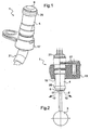
- the figure 1 represents a position sensor 1 according to the invention, adapted to be mounted on a casing 13 of manual or automatic transmission of a motor vehicle, to determine the position of the gearbox.
- This sensor 1 is particularly suitable for the detection of neutral on vehicles equipped with the system "STOP & START" stopping the engine when the vehicle stops and restarting it automatically or under the command of the driver.
- the gearbox (not visible) comprises an actuating element 3 of the various gear ratios ( figure 2 ) depending on the commands applied by a gear lever via a linkage (see for example the gearbox described in EP 0 273 874 ).
- the actuating element 3 may be, for example, an actuating rod, a fork or a cam of the gearbox.
- the position sensor -1 comprises inside a casing 4 on the one hand, a magnet 5 for example annular and on the other hand, a probe 7 able to measure a magnetic field at a sensitive end 9 of the sensor 1.
- the probe is preferably Hall effect.
- the sensitive end 9 is likely to face a moving target 11 linked to the actuating element 3 of the gearbox ratios to determine the position in the space of the target 11 and to deduce the position therefrom. of the gearbox.
- the target 11 is linked to the actuating element 3 of the gears of the gearbox to be mobile with it in rotation (see arrows 12 on the figure 2 ) or in translation and be representative of an engaged speed or neutral.
- the end 9 of the sensor 1 faces the target 11 when the gearbox is in neutral.
- the gearbox comprises a housing 13 isolating an inner zone of the gearbox lubricated from an outer zone and traversed by the sensor 1 at a sealed passage 15.
- the senor 1 comprises a fastening flange 17 for fixing the sensor 1 to the casing 13.
- the sensor 1 further comprises a casing 4 advantageously comprising sealing means adapted to cooperate with the casing 13, to isolate the inner zone of the gearbox with the outer zone.
- the sealing means comprise for example a seal.
- the senor 1 advantageously comprises, at the level of the outer zone of the casing 13, an electrical connector 21 that can be connected to a cable, in particular for powering and transmitting the signals of the sensor 1 (see FIG. figure 1 ).
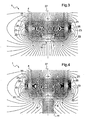
- the magnet 5 is placed near the probe 7, so that the probe 7 is traversed by the magnetic field lines 23 formed between the magnet 5 and the target 11.
- the magnetic field of the magnet 5 is deformed towards the target 11 and the probe 7 measures a high magnetic induction at an air gap E between the sensor 1 and the target 11.
- the magnetic field loops naturally around the magnet 5 and the probe 7 measures a weak magnetic induction.
- the senor 1 comprises at least one ferromagnetic element 25 placed at the periphery of the sensitive end 9, for trapping metal contaminants.
- the ferromagnetic element 25 thus makes it possible to create two zones Z1 and Z2 of strong magnetic field, concentrated on the periphery of the end 9 to attract the metallic contaminants instead of being drawn into the gap E between the end 9 and the target 11.
- the contaminants are attracted to the zones Z1 and Z2 remote from the sensitive end 9, on either side of the ferromagnetic element 25, so that they do not influence the measurement made by the probe 7.
- the ferromagnetic element 25 reduces the magnetic field in a third zone Z3 located at the periphery of the end 9 of the sensor 1, ( figures 4 and 5) thus limiting the attraction of contaminants to the sensor 1.
- the projections of lubricants and the movement of the target 11 promote the displacement of metal contaminants attached to the sensitive end 9 to Z1 and Z2 areas.
- the ferromagnetic element 25 has the shape of a ring capable of cooperating with a complementary shape of the sensor 1.
- a ring 25 that is radially sectioned and able to move away elastically in order to be slid into a corresponding groove of the envelope 4 of the sensor 1, so that in the assembled state the ring 25 is closed around the end 9 (not shown).
- the ferromagnetic element 25 is placed outside the envelope 4 of the sensor 1.
- the ferromagnetic element 25 forms a barrier to prevent the flow of contaminants along the envelope 4 towards the sensitive end 9.
- the ferromagnetic element 25 comprises clipping means capable of cooperating with the envelope 4 of the sensor 1 to fix the ferromagnetic element 25 to the envelope 4.
- the ferromagnetic element 25 is placed inside the envelope 4 of the sensor 1.
- the annular magnetic element 25 and the magnet 5 have a common axis of revolution 27.
- the senor 1 comprises a plurality of ferromagnetic elements 25 placed at the periphery of the sensitive end 9.
- a magnetic effect gearbox position sensor 1 comprising a ferromagnetic element 25 placed at the periphery of its sensitive end 9, makes it possible to trap metal contaminants outside the sensitive end 9 that may be in danger. look with the target 11 for the determination of the position of the gearbox.
Landscapes
- Engineering & Computer Science (AREA)
- General Engineering & Computer Science (AREA)
- Physics & Mathematics (AREA)
- General Physics & Mathematics (AREA)
- Mechanical Engineering (AREA)
- Measurement Of Length, Angles, Or The Like Using Electric Or Magnetic Means (AREA)
- Gear-Shifting Mechanisms (AREA)
- Control Of Transmission Device (AREA)
- Burglar Alarm Systems (AREA)
Claims (10)
- Stellungssensor für ein Schaltgetriebe eines Kraftfahrzeugs, der einen Magneten (5) und eine Sonde (7) enthält, die ein Magnetfeld messen kann, das auf Höhe eines Abfühlendes (9) vorhanden ist, das sich gegenüber einem beweglichen Ziel (11) befinden kann, das mit einem Betätigungselement (3) für Übersetzungsverhältnisse eines Schaltgetriebes verbunden sein kann, um die räumliche Position des Ziels (11) zu bestimmen und um daraus die Stellung des Schaltgetriebes abzuleiten, dadurch gekennzeichnet, dass er außerdem wenigstens ein ferromagnetisches Element (25) enthält, das am Umfang des Abfühlendes (9) angeordnet ist, um metallische Verunreinigungen einzufangen.
- Stellungssensor nach Anspruch 1, dadurch gekennzeichnet, dass das ferromagnetische Element (25) die Form eines Rings aufweist, der mit einer komplementären Form des Sensors (1) zusammenwirken kann.
- Stellungssensor nach einem der vorhergehenden Ansprüche, dadurch gekennzeichnet, dass das ferromagnetische Element (25) außerhalb einer Hülle (4) des Sensors (1) angeordnet ist.
- Stellungssensor nach Anspruch 3, dadurch gekennzeichnet, dass das ferromagnetische Element (25) Einrastmittel aufweist, die mit der Hülle (4) des Sensors zusammenwirken können, um das ferromagnetische Element (25) an der Hülle (4) zu fixieren.
- Stellungssensor nach einem der Ansprüche 1 oder 2, dadurch gekennzeichnet, dass das ferromagnetische Element (25) in einer Hülle (4) des Sensors (1) angeordnet ist.
- Stellungssensor nach einem der Ansprüche 2 bis 5, dadurch gekennzeichnet, dass das ringförmige ferromagnetische Element (25) und der Magnet (5) eine gemeinsame Rotationssymmetrieachse (27) besitzen.
- Stellungssensor nach einem der vorhergehenden Ansprüche, dadurch gekennzeichnet, dass er mehrere ferromagnetische Elemente (25) aufweist, die am Umfang des Abfühlendes (9) angeordnet sind.
- Stellungssensor nach dem vorhergehenden Anspruch, dadurch gekennzeichnet, dass die Sonde (7) eine Hall-Effekt-Sonde ist.
- Schaltgetriebe für Kraftfahrzeug, mit einem Betätigungselement (3) für die Übersetzungsverhältnisse und einem beweglichen Ziel (11), das mit dem Betätigungselement (3) verbunden ist, dadurch gekennzeichnet, dass es einen Stellungssensor (1) nach einem der vorhergehenden Ansprüche enthält.
- Schaltgetriebe nach dem vorhergehenden Anspruch, dadurch gekennzeichnet, dass das Abfühlende (9) des Stellungssensors (1) dem Ziel (11) zugewandt ist, wenn das Betätigungselement (3) für die Übersetzungsverhältnisse des Schaltgetriebes am Totpunkt ist.
Priority Applications (1)
| Application Number | Priority Date | Filing Date | Title |
|---|---|---|---|
| PL08872818T PL2222984T3 (pl) | 2007-12-17 | 2008-12-15 | Czujnik położenia skrzyni biegów i odpowiednia skrzynia biegów |
Applications Claiming Priority (2)
| Application Number | Priority Date | Filing Date | Title |
|---|---|---|---|
| FR0708767A FR2925139B1 (fr) | 2007-12-17 | 2007-12-17 | Capteur de position d'une boite de vitesses et boite de vitesses correspondante |
| PCT/FR2008/001739 WO2009106701A1 (fr) | 2007-12-17 | 2008-12-15 | Capteur de position d'une boite de vitesses et boite de vitesses correspondante |
Publications (2)
| Publication Number | Publication Date |
|---|---|
| EP2222984A1 EP2222984A1 (de) | 2010-09-01 |
| EP2222984B1 true EP2222984B1 (de) | 2011-06-22 |
Family
ID=39496468
Family Applications (1)
| Application Number | Title | Priority Date | Filing Date |
|---|---|---|---|
| EP08872818A Not-in-force EP2222984B1 (de) | 2007-12-17 | 2008-12-15 | Getriebepositionssensor und zugehöriges getriebe |
Country Status (12)
| Country | Link |
|---|---|
| US (1) | US8493063B2 (de) |
| EP (1) | EP2222984B1 (de) |
| JP (1) | JP5199389B2 (de) |
| KR (1) | KR101549279B1 (de) |
| CN (1) | CN101946107B (de) |
| AT (1) | ATE514019T1 (de) |
| BR (1) | BRPI0821206A2 (de) |
| ES (1) | ES2368022T3 (de) |
| FR (1) | FR2925139B1 (de) |
| PL (1) | PL2222984T3 (de) |
| PT (1) | PT2222984E (de) |
| WO (1) | WO2009106701A1 (de) |
Families Citing this family (7)
| Publication number | Priority date | Publication date | Assignee | Title |
|---|---|---|---|---|
| US9157970B2 (en) | 2011-04-05 | 2015-10-13 | Ford Global Technologies, Llc | Method and apparatus for preventing contamination from affecting magnetic field sensors |
| CN102537341B (zh) * | 2011-12-26 | 2016-01-20 | 联合汽车电子有限公司 | 空档位置传感器 |
| WO2014068750A1 (ja) * | 2012-11-01 | 2014-05-08 | トヨタ自動車株式会社 | 捩り振動減衰装置 |
| JP5936126B2 (ja) * | 2012-11-29 | 2016-06-15 | アルプス電気株式会社 | 磁気検知式スイッチを使用したシフトレバー装置 |
| GB2535556B (en) | 2015-07-14 | 2017-06-28 | Longvale Ltd | Electrical Process Control Sensor Assemblies |
| ES2651315B2 (es) * | 2016-07-25 | 2018-05-14 | Bitron Industrie España, S.A. | Sistema de detección de la posición de una caja de velocidades manual, caja de velocidades y método de detección de posición de marcha |
| US10514092B2 (en) * | 2016-12-19 | 2019-12-24 | Eaton Corporation | Position sensor body assembly |
Family Cites Families (28)
| Publication number | Priority date | Publication date | Assignee | Title |
|---|---|---|---|---|
| US2225205A (en) * | 1937-06-01 | 1940-12-17 | Lisle Corp | Magnetic plug |
| DE3138827A1 (de) * | 1981-09-30 | 1983-04-14 | Wabco Westinghouse Fahrzeugbremsen GmbH, 3000 Hannover | Gangwaehler fuer ein getriebe |
| DE3434205A1 (de) * | 1984-09-18 | 1986-03-27 | Wabco Westinghouse Fahrzeugbremsen GmbH, 3000 Hannover | Geber fuer ein schaltgetriebe eines kraftfahrzeugs |
| US4676115A (en) * | 1985-05-13 | 1987-06-30 | Eaton Corporation | Semi-automatic transmission |
| IT1196818B (it) | 1986-02-04 | 1988-11-25 | Fiat Auto Spa | Dispositivo di comando per cambi di velocita di autoveicoli |
| US4700133A (en) * | 1986-02-28 | 1987-10-13 | Ssi Technologies, Inc. | Variable reluctance magnetic sensor with pole piece and shell projections matched to gear teeth |
| JPS62221925A (ja) * | 1986-03-24 | 1987-09-30 | Fuji Tool & Die Co Ltd | 変速操作機構 |
| US4745363A (en) * | 1986-07-16 | 1988-05-17 | North American Philips Corporation | Non-oriented direct coupled gear tooth sensor using a Hall cell |
| JPH0625739Y2 (ja) * | 1987-02-09 | 1994-07-06 | 自動車機器株式会社 | 変速機のギヤ位置センサ |
| JPH01194844A (ja) * | 1988-01-28 | 1989-08-04 | Mitsubishi Electric Corp | 速度発電機の保護装置 |
| DE3929937A1 (de) * | 1989-09-08 | 1991-03-21 | Vdo Schindling | Mit magnetkraeften arbeitender endlagensensor |
| US5450009A (en) * | 1990-12-28 | 1995-09-12 | Kabushiki Kaisha Komatsu Seisakusho | Magnetic sensor and structure of its mounting |
| AU3524093A (en) * | 1992-03-27 | 1993-09-30 | Kao Corporation | Nonionic powdery detergent composition and process for producing the same |
| JP3398431B2 (ja) * | 1993-09-27 | 2003-04-21 | マツダ株式会社 | 電子制御変速機 |
| FR2724723B1 (fr) * | 1994-09-16 | 1998-09-11 | Moving Magnet Tech | Capteur incremental de vitesse et/ou de position. |
| US5781005A (en) * | 1995-06-07 | 1998-07-14 | Allegro Microsystems, Inc. | Hall-effect ferromagnetic-article-proximity sensor |
| DE19731960A1 (de) * | 1996-07-29 | 1998-02-05 | Caterpillar Inc | Elektronischer Widerstandsüberwachungspartikeldetektor |
| US5743143A (en) * | 1996-08-09 | 1998-04-28 | Eaton Corporation | Transmission shifting mechanism and position sensor |
| DE19650154C2 (de) * | 1996-12-04 | 1999-06-10 | Lemfoerder Metallwaren Ag | Schaltvorrichtung für ein Getriebe eines KFZ mit einer mit Sensoren, Leuchtdioden, Prozessen und anderen elektronischen Bauelementen bestückten Leiterplatte und Verfahren zur Herstellung einer gekrümmten Leiterplatte zur Verwendung in einer solchen Schaltvorrichtung |
| US6205858B1 (en) * | 1999-11-24 | 2001-03-27 | Delphi Technologies, Inc. | Vehicle speed sensor |
| FR2837569B1 (fr) * | 2002-03-19 | 2004-07-16 | Electricfil | Capteur de position et/ou de vitesse de type magnetique |
| JP4470577B2 (ja) * | 2004-05-14 | 2010-06-02 | 株式会社デンソー | 回転角度検出装置 |
| JP2006029441A (ja) * | 2004-07-15 | 2006-02-02 | Nissan Motor Co Ltd | シフトフォークの位置検知装置 |
| DE102004056800A1 (de) * | 2004-11-24 | 2006-06-01 | Zf Friedrichshafen Ag | Schaltvorrichtung für ein Kraftfahrzeug |
| JP4344343B2 (ja) * | 2005-06-15 | 2009-10-14 | 本田技研工業株式会社 | 自動変速機のシフト装置 |
| JP4877905B2 (ja) * | 2005-08-03 | 2012-02-15 | 日産自動車株式会社 | 自動マニュアルトランスミッションのシフト位置検出装置 |
| KR100761634B1 (ko) * | 2006-08-09 | 2007-09-27 | 위아 주식회사 | 자동차용 수동변속기의 변속레버 중립상태 감지장치 |
| FR2932880B1 (fr) * | 2008-06-19 | 2010-08-20 | Continental Automotive France | Dispositif de mesure de position par effet hall |
-
2007
- 2007-12-17 FR FR0708767A patent/FR2925139B1/fr not_active Expired - Fee Related
-
2008
- 2008-12-15 PL PL08872818T patent/PL2222984T3/pl unknown
- 2008-12-15 WO PCT/FR2008/001739 patent/WO2009106701A1/fr not_active Ceased
- 2008-12-15 JP JP2010538829A patent/JP5199389B2/ja not_active Expired - Fee Related
- 2008-12-15 EP EP08872818A patent/EP2222984B1/de not_active Not-in-force
- 2008-12-15 KR KR1020107015596A patent/KR101549279B1/ko not_active Expired - Fee Related
- 2008-12-15 CN CN200880126935.7A patent/CN101946107B/zh not_active Expired - Fee Related
- 2008-12-15 BR BRPI0821206-6A patent/BRPI0821206A2/pt not_active IP Right Cessation
- 2008-12-15 PT PT08872818T patent/PT2222984E/pt unknown
- 2008-12-15 AT AT08872818T patent/ATE514019T1/de not_active IP Right Cessation
- 2008-12-15 US US12/808,198 patent/US8493063B2/en not_active Expired - Fee Related
- 2008-12-15 ES ES08872818T patent/ES2368022T3/es active Active
Also Published As
| Publication number | Publication date |
|---|---|
| JP5199389B2 (ja) | 2013-05-15 |
| CN101946107A (zh) | 2011-01-12 |
| PT2222984E (pt) | 2011-07-27 |
| WO2009106701A1 (fr) | 2009-09-03 |
| KR101549279B1 (ko) | 2015-09-01 |
| CN101946107B (zh) | 2014-04-23 |
| ATE514019T1 (de) | 2011-07-15 |
| PL2222984T3 (pl) | 2011-11-30 |
| US8493063B2 (en) | 2013-07-23 |
| FR2925139A1 (fr) | 2009-06-19 |
| US20100308802A1 (en) | 2010-12-09 |
| EP2222984A1 (de) | 2010-09-01 |
| FR2925139B1 (fr) | 2010-01-08 |
| JP2011506891A (ja) | 2011-03-03 |
| ES2368022T3 (es) | 2011-11-11 |
| KR20100096243A (ko) | 2010-09-01 |
| BRPI0821206A2 (pt) | 2015-06-16 |
Similar Documents
| Publication | Publication Date | Title |
|---|---|---|
| EP2222984B1 (de) | Getriebepositionssensor und zugehöriges getriebe | |
| FR2829815A1 (fr) | Butee pour embrayage equipee d'un capteur magnetique | |
| EP2534396B1 (de) | Vorrichtung zur erkennung der neutralen position eines hebels zum wählen und schalten von gängen in einem motorfahrzeuggetriebe | |
| EP1882871A1 (de) | Kraftfahrzeuggetriebe mit einem magnetischen Hall-Sensor | |
| FR2688853A1 (fr) | Dispositif pour la detection de la vitesse engagee d'une boite de vitesse de vehicule a moteur. | |
| FR2762056A1 (fr) | Palier a roulement a capteur d'informations | |
| EP2870383B1 (de) | Vorrichtung zur erfassung der linearen position eines übertragungselements in form eines kabels an einem hebel eines kraftfahrzeuggetriebes | |
| FR2859050A1 (fr) | Unite d'entrainement et de transmission comportant au moins deux moteurs pour actionner ou deplacer une piece equipant un vehicule automobile | |
| FR2784061A1 (fr) | Transmission comportant un capteur a effet hall | |
| FR3056270B1 (fr) | Cylindre hydraulique recepteur equipe d'un capteur de position | |
| EP4356023A1 (de) | Elektromagnetische betätigungsvorrichtung und übertragungssystem mit dieser elektromagnetischen betätigungsvorrichtung | |
| FR2919365A1 (fr) | Dispositif de mesure de la position d'une butee d'embrayage et embrayage comprenant un tel dispositif. | |
| FR2986589A1 (fr) | Mecanisme d'entrainement en rotation d'un arbre tournant au moyen d'un organe moteur | |
| FR2909168A3 (fr) | Capteur de position magnetique | |
| FR2764030A1 (fr) | Dispositif d'actionnement d'une boite a vitesses automatisee | |
| FR3154263A1 (fr) | Actionneur électromagnétique linéaire | |
| FR3130915A1 (fr) | Système de transmission comportant un dispositif d’entraînement différentiel | |
| FR2983930A1 (fr) | Mecanisme d'entrainement en rotation d'un arbre tournant au moyen d'une courroie | |
| EP4610611A1 (de) | System zur bestimmung einer drehinformation eines organs | |
| FR3142252A1 (fr) | Système de détermination d’un couple appliqué entre deux organes | |
| FR2774227A1 (fr) | Dispositif de fixation d'une bague magnetique sur un arbre d'un moteur d'activation d'un organe fonctionnel de vehicule automobile | |
| FR3140674A1 (fr) | Système de détermination d’un couple entre deux organes tournants | |
| FR3028902A1 (fr) | Palier a roulement | |
| FR3038772A1 (fr) | Actionneur electromagnetique a entrainement direct. | |
| FR3038935A1 (fr) | Systeme comprenant un rotor monte en rotation par rapport a un organe fixe |
Legal Events
| Date | Code | Title | Description |
|---|---|---|---|
| PUAI | Public reference made under article 153(3) epc to a published international application that has entered the european phase |
Free format text: ORIGINAL CODE: 0009012 |
|
| 17P | Request for examination filed |
Effective date: 20100604 |
|
| AK | Designated contracting states |
Kind code of ref document: A1 Designated state(s): AT BE BG CH CY CZ DE DK EE ES FI FR GB GR HR HU IE IS IT LI LT LU LV MC MT NL NO PL PT RO SE SI SK TR |
|
| AX | Request for extension of the european patent |
Extension state: AL BA MK RS |
|
| GRAP | Despatch of communication of intention to grant a patent |
Free format text: ORIGINAL CODE: EPIDOSNIGR1 |
|
| DAX | Request for extension of the european patent (deleted) | ||
| GRAS | Grant fee paid |
Free format text: ORIGINAL CODE: EPIDOSNIGR3 |
|
| GRAA | (expected) grant |
Free format text: ORIGINAL CODE: 0009210 |
|
| AK | Designated contracting states |
Kind code of ref document: B1 Designated state(s): AT BE BG CH CY CZ DE DK EE ES FI FR GB GR HR HU IE IS IT LI LT LU LV MC MT NL NO PL PT RO SE SI SK TR |
|
| REG | Reference to a national code |
Ref country code: GB Ref legal event code: FG4D Free format text: NOT ENGLISH |
|
| REG | Reference to a national code |
Ref country code: CH Ref legal event code: EP |
|
| REG | Reference to a national code |
Ref country code: RO Ref legal event code: EPE |
|
| REG | Reference to a national code |
Ref country code: IE Ref legal event code: FG4D Free format text: LANGUAGE OF EP DOCUMENT: FRENCH |
|
| REG | Reference to a national code |
Ref country code: PT Ref legal event code: SC4A Free format text: AVAILABILITY OF NATIONAL TRANSLATION Effective date: 20110720 |
|
| REG | Reference to a national code |
Ref country code: SE Ref legal event code: TRGR |
|
| REG | Reference to a national code |
Ref country code: DE Ref legal event code: R096 Ref document number: 602008007862 Country of ref document: DE Effective date: 20110811 |
|
| REG | Reference to a national code |
Ref country code: NL Ref legal event code: VDEP Effective date: 20110622 |
|
| PG25 | Lapsed in a contracting state [announced via postgrant information from national office to epo] |
Ref country code: NO Free format text: LAPSE BECAUSE OF FAILURE TO SUBMIT A TRANSLATION OF THE DESCRIPTION OR TO PAY THE FEE WITHIN THE PRESCRIBED TIME-LIMIT Effective date: 20110922 Ref country code: HR Free format text: LAPSE BECAUSE OF FAILURE TO SUBMIT A TRANSLATION OF THE DESCRIPTION OR TO PAY THE FEE WITHIN THE PRESCRIBED TIME-LIMIT Effective date: 20110622 Ref country code: LT Free format text: LAPSE BECAUSE OF FAILURE TO SUBMIT A TRANSLATION OF THE DESCRIPTION OR TO PAY THE FEE WITHIN THE PRESCRIBED TIME-LIMIT Effective date: 20110622 |
|
| REG | Reference to a national code |
Ref country code: ES Ref legal event code: FG2A Ref document number: 2368022 Country of ref document: ES Kind code of ref document: T3 Effective date: 20111111 |
|
| PG25 | Lapsed in a contracting state [announced via postgrant information from national office to epo] |
Ref country code: GR Free format text: LAPSE BECAUSE OF FAILURE TO SUBMIT A TRANSLATION OF THE DESCRIPTION OR TO PAY THE FEE WITHIN THE PRESCRIBED TIME-LIMIT Effective date: 20110923 Ref country code: LV Free format text: LAPSE BECAUSE OF FAILURE TO SUBMIT A TRANSLATION OF THE DESCRIPTION OR TO PAY THE FEE WITHIN THE PRESCRIBED TIME-LIMIT Effective date: 20110622 Ref country code: FI Free format text: LAPSE BECAUSE OF FAILURE TO SUBMIT A TRANSLATION OF THE DESCRIPTION OR TO PAY THE FEE WITHIN THE PRESCRIBED TIME-LIMIT Effective date: 20110622 Ref country code: AT Free format text: LAPSE BECAUSE OF FAILURE TO SUBMIT A TRANSLATION OF THE DESCRIPTION OR TO PAY THE FEE WITHIN THE PRESCRIBED TIME-LIMIT Effective date: 20110622 Ref country code: CY Free format text: LAPSE BECAUSE OF FAILURE TO SUBMIT A TRANSLATION OF THE DESCRIPTION OR TO PAY THE FEE WITHIN THE PRESCRIBED TIME-LIMIT Effective date: 20110622 Ref country code: SI Free format text: LAPSE BECAUSE OF FAILURE TO SUBMIT A TRANSLATION OF THE DESCRIPTION OR TO PAY THE FEE WITHIN THE PRESCRIBED TIME-LIMIT Effective date: 20110622 |
|
| REG | Reference to a national code |
Ref country code: PL Ref legal event code: T3 |
|
| REG | Reference to a national code |
Ref country code: SK Ref legal event code: T3 Ref document number: E 10103 Country of ref document: SK |
|
| PG25 | Lapsed in a contracting state [announced via postgrant information from national office to epo] |
Ref country code: NL Free format text: LAPSE BECAUSE OF FAILURE TO SUBMIT A TRANSLATION OF THE DESCRIPTION OR TO PAY THE FEE WITHIN THE PRESCRIBED TIME-LIMIT Effective date: 20110622 |
|
| REG | Reference to a national code |
Ref country code: IE Ref legal event code: FD4D |
|
| PG25 | Lapsed in a contracting state [announced via postgrant information from national office to epo] |
Ref country code: EE Free format text: LAPSE BECAUSE OF FAILURE TO SUBMIT A TRANSLATION OF THE DESCRIPTION OR TO PAY THE FEE WITHIN THE PRESCRIBED TIME-LIMIT Effective date: 20110622 Ref country code: IE Free format text: LAPSE BECAUSE OF FAILURE TO SUBMIT A TRANSLATION OF THE DESCRIPTION OR TO PAY THE FEE WITHIN THE PRESCRIBED TIME-LIMIT Effective date: 20110622 Ref country code: IS Free format text: LAPSE BECAUSE OF FAILURE TO SUBMIT A TRANSLATION OF THE DESCRIPTION OR TO PAY THE FEE WITHIN THE PRESCRIBED TIME-LIMIT Effective date: 20111022 |
|
| PLBE | No opposition filed within time limit |
Free format text: ORIGINAL CODE: 0009261 |
|
| STAA | Information on the status of an ep patent application or granted ep patent |
Free format text: STATUS: NO OPPOSITION FILED WITHIN TIME LIMIT |
|
| 26N | No opposition filed |
Effective date: 20120323 |
|
| PG25 | Lapsed in a contracting state [announced via postgrant information from national office to epo] |
Ref country code: DK Free format text: LAPSE BECAUSE OF FAILURE TO SUBMIT A TRANSLATION OF THE DESCRIPTION OR TO PAY THE FEE WITHIN THE PRESCRIBED TIME-LIMIT Effective date: 20110622 |
|
| BERE | Be: lapsed |
Owner name: SC2N Effective date: 20111231 |
|
| REG | Reference to a national code |
Ref country code: DE Ref legal event code: R097 Ref document number: 602008007862 Country of ref document: DE Effective date: 20120323 |
|
| PG25 | Lapsed in a contracting state [announced via postgrant information from national office to epo] |
Ref country code: MC Free format text: LAPSE BECAUSE OF NON-PAYMENT OF DUE FEES Effective date: 20111231 |
|
| PG25 | Lapsed in a contracting state [announced via postgrant information from national office to epo] |
Ref country code: BE Free format text: LAPSE BECAUSE OF NON-PAYMENT OF DUE FEES Effective date: 20111231 |
|
| PG25 | Lapsed in a contracting state [announced via postgrant information from national office to epo] |
Ref country code: MT Free format text: LAPSE BECAUSE OF FAILURE TO SUBMIT A TRANSLATION OF THE DESCRIPTION OR TO PAY THE FEE WITHIN THE PRESCRIBED TIME-LIMIT Effective date: 20110622 |
|
| PG25 | Lapsed in a contracting state [announced via postgrant information from national office to epo] |
Ref country code: LU Free format text: LAPSE BECAUSE OF NON-PAYMENT OF DUE FEES Effective date: 20111215 |
|
| PG25 | Lapsed in a contracting state [announced via postgrant information from national office to epo] |
Ref country code: BG Free format text: LAPSE BECAUSE OF FAILURE TO SUBMIT A TRANSLATION OF THE DESCRIPTION OR TO PAY THE FEE WITHIN THE PRESCRIBED TIME-LIMIT Effective date: 20110922 |
|
| REG | Reference to a national code |
Ref country code: CH Ref legal event code: PL |
|
| PG25 | Lapsed in a contracting state [announced via postgrant information from national office to epo] |
Ref country code: TR Free format text: LAPSE BECAUSE OF FAILURE TO SUBMIT A TRANSLATION OF THE DESCRIPTION OR TO PAY THE FEE WITHIN THE PRESCRIBED TIME-LIMIT Effective date: 20110622 |
|
| PG25 | Lapsed in a contracting state [announced via postgrant information from national office to epo] |
Ref country code: HU Free format text: LAPSE BECAUSE OF FAILURE TO SUBMIT A TRANSLATION OF THE DESCRIPTION OR TO PAY THE FEE WITHIN THE PRESCRIBED TIME-LIMIT Effective date: 20110622 Ref country code: LI Free format text: LAPSE BECAUSE OF NON-PAYMENT OF DUE FEES Effective date: 20121231 Ref country code: CH Free format text: LAPSE BECAUSE OF NON-PAYMENT OF DUE FEES Effective date: 20121231 |
|
| REG | Reference to a national code |
Ref country code: FR Ref legal event code: PLFP Year of fee payment: 8 |
|
| REG | Reference to a national code |
Ref country code: FR Ref legal event code: PLFP Year of fee payment: 9 |
|
| PGFP | Annual fee paid to national office [announced via postgrant information from national office to epo] |
Ref country code: GB Payment date: 20161221 Year of fee payment: 9 Ref country code: CZ Payment date: 20161124 Year of fee payment: 9 Ref country code: SK Payment date: 20161123 Year of fee payment: 9 |
|
| PGFP | Annual fee paid to national office [announced via postgrant information from national office to epo] |
Ref country code: PT Payment date: 20161122 Year of fee payment: 9 Ref country code: ES Payment date: 20161229 Year of fee payment: 9 Ref country code: RO Payment date: 20161129 Year of fee payment: 9 Ref country code: PL Payment date: 20161129 Year of fee payment: 9 Ref country code: IT Payment date: 20161214 Year of fee payment: 9 Ref country code: FR Payment date: 20161229 Year of fee payment: 9 Ref country code: SE Payment date: 20161219 Year of fee payment: 9 |
|
| PGFP | Annual fee paid to national office [announced via postgrant information from national office to epo] |
Ref country code: DE Payment date: 20161221 Year of fee payment: 9 |
|
| REG | Reference to a national code |
Ref country code: DE Ref legal event code: R119 Ref document number: 602008007862 Country of ref document: DE |
|
| PG25 | Lapsed in a contracting state [announced via postgrant information from national office to epo] |
Ref country code: PT Free format text: LAPSE BECAUSE OF NON-PAYMENT OF DUE FEES Effective date: 20180615 Ref country code: CZ Free format text: LAPSE BECAUSE OF NON-PAYMENT OF DUE FEES Effective date: 20171215 |
|
| GBPC | Gb: european patent ceased through non-payment of renewal fee |
Effective date: 20171215 |
|
| PG25 | Lapsed in a contracting state [announced via postgrant information from national office to epo] |
Ref country code: SE Free format text: LAPSE BECAUSE OF NON-PAYMENT OF DUE FEES Effective date: 20171216 Ref country code: RO Free format text: LAPSE BECAUSE OF NON-PAYMENT OF DUE FEES Effective date: 20171215 |
|
| REG | Reference to a national code |
Ref country code: SK Ref legal event code: MM4A Ref document number: E 10103 Country of ref document: SK Effective date: 20171215 |
|
| REG | Reference to a national code |
Ref country code: FR Ref legal event code: ST Effective date: 20180831 |
|
| PG25 | Lapsed in a contracting state [announced via postgrant information from national office to epo] |
Ref country code: IT Free format text: LAPSE BECAUSE OF NON-PAYMENT OF DUE FEES Effective date: 20171215 Ref country code: FR Free format text: LAPSE BECAUSE OF NON-PAYMENT OF DUE FEES Effective date: 20180102 Ref country code: DE Free format text: LAPSE BECAUSE OF NON-PAYMENT OF DUE FEES Effective date: 20180703 |
|
| PG25 | Lapsed in a contracting state [announced via postgrant information from national office to epo] |
Ref country code: GB Free format text: LAPSE BECAUSE OF NON-PAYMENT OF DUE FEES Effective date: 20171215 Ref country code: SK Free format text: LAPSE BECAUSE OF NON-PAYMENT OF DUE FEES Effective date: 20171215 |
|
| PG25 | Lapsed in a contracting state [announced via postgrant information from national office to epo] |
Ref country code: PL Free format text: LAPSE BECAUSE OF NON-PAYMENT OF DUE FEES Effective date: 20171215 |
|
| REG | Reference to a national code |
Ref country code: ES Ref legal event code: FD2A Effective date: 20190703 |
|
| PG25 | Lapsed in a contracting state [announced via postgrant information from national office to epo] |
Ref country code: ES Free format text: LAPSE BECAUSE OF NON-PAYMENT OF DUE FEES Effective date: 20171216 |