EP2221523B1 - High efficiency light emitting diode apparatus - Google Patents
High efficiency light emitting diode apparatus Download PDFInfo
- Publication number
- EP2221523B1 EP2221523B1 EP09157986A EP09157986A EP2221523B1 EP 2221523 B1 EP2221523 B1 EP 2221523B1 EP 09157986 A EP09157986 A EP 09157986A EP 09157986 A EP09157986 A EP 09157986A EP 2221523 B1 EP2221523 B1 EP 2221523B1
- Authority
- EP
- European Patent Office
- Prior art keywords
- light emitting
- emitting diode
- high efficiency
- heat dissipating
- passage
- Prior art date
- Legal status (The legal status is an assumption and is not a legal conclusion. Google has not performed a legal analysis and makes no representation as to the accuracy of the status listed.)
- Not-in-force
Links
Images







Classifications
-
- F—MECHANICAL ENGINEERING; LIGHTING; HEATING; WEAPONS; BLASTING
- F21—LIGHTING
- F21V—FUNCTIONAL FEATURES OR DETAILS OF LIGHTING DEVICES OR SYSTEMS THEREOF; STRUCTURAL COMBINATIONS OF LIGHTING DEVICES WITH OTHER ARTICLES, NOT OTHERWISE PROVIDED FOR
- F21V29/00—Protecting lighting devices from thermal damage; Cooling or heating arrangements specially adapted for lighting devices or systems
- F21V29/50—Cooling arrangements
- F21V29/70—Cooling arrangements characterised by passive heat-dissipating elements, e.g. heat-sinks
-
- F—MECHANICAL ENGINEERING; LIGHTING; HEATING; WEAPONS; BLASTING
- F21—LIGHTING
- F21V—FUNCTIONAL FEATURES OR DETAILS OF LIGHTING DEVICES OR SYSTEMS THEREOF; STRUCTURAL COMBINATIONS OF LIGHTING DEVICES WITH OTHER ARTICLES, NOT OTHERWISE PROVIDED FOR
- F21V3/00—Globes; Bowls; Cover glasses
- F21V3/02—Globes; Bowls; Cover glasses characterised by the shape
-
- F—MECHANICAL ENGINEERING; LIGHTING; HEATING; WEAPONS; BLASTING
- F21—LIGHTING
- F21K—NON-ELECTRIC LIGHT SOURCES USING LUMINESCENCE; LIGHT SOURCES USING ELECTROCHEMILUMINESCENCE; LIGHT SOURCES USING CHARGES OF COMBUSTIBLE MATERIAL; LIGHT SOURCES USING SEMICONDUCTOR DEVICES AS LIGHT-GENERATING ELEMENTS; LIGHT SOURCES NOT OTHERWISE PROVIDED FOR
- F21K9/00—Light sources using semiconductor devices as light-generating elements, e.g. using light-emitting diodes [LED] or lasers
- F21K9/20—Light sources comprising attachment means
- F21K9/23—Retrofit light sources for lighting devices with a single fitting for each light source, e.g. for substitution of incandescent lamps with bayonet or threaded fittings
- F21K9/232—Retrofit light sources for lighting devices with a single fitting for each light source, e.g. for substitution of incandescent lamps with bayonet or threaded fittings specially adapted for generating an essentially omnidirectional light distribution, e.g. with a glass bulb
-
- F—MECHANICAL ENGINEERING; LIGHTING; HEATING; WEAPONS; BLASTING
- F21—LIGHTING
- F21K—NON-ELECTRIC LIGHT SOURCES USING LUMINESCENCE; LIGHT SOURCES USING ELECTROCHEMILUMINESCENCE; LIGHT SOURCES USING CHARGES OF COMBUSTIBLE MATERIAL; LIGHT SOURCES USING SEMICONDUCTOR DEVICES AS LIGHT-GENERATING ELEMENTS; LIGHT SOURCES NOT OTHERWISE PROVIDED FOR
- F21K9/00—Light sources using semiconductor devices as light-generating elements, e.g. using light-emitting diodes [LED] or lasers
- F21K9/60—Optical arrangements integrated in the light source, e.g. for improving the colour rendering index or the light extraction
- F21K9/61—Optical arrangements integrated in the light source, e.g. for improving the colour rendering index or the light extraction using light guides
-
- F—MECHANICAL ENGINEERING; LIGHTING; HEATING; WEAPONS; BLASTING
- F21—LIGHTING
- F21V—FUNCTIONAL FEATURES OR DETAILS OF LIGHTING DEVICES OR SYSTEMS THEREOF; STRUCTURAL COMBINATIONS OF LIGHTING DEVICES WITH OTHER ARTICLES, NOT OTHERWISE PROVIDED FOR
- F21V29/00—Protecting lighting devices from thermal damage; Cooling or heating arrangements specially adapted for lighting devices or systems
- F21V29/50—Cooling arrangements
- F21V29/502—Cooling arrangements characterised by the adaptation for cooling of specific components
- F21V29/506—Cooling arrangements characterised by the adaptation for cooling of specific components of globes, bowls or cover glasses
-
- F—MECHANICAL ENGINEERING; LIGHTING; HEATING; WEAPONS; BLASTING
- F21—LIGHTING
- F21V—FUNCTIONAL FEATURES OR DETAILS OF LIGHTING DEVICES OR SYSTEMS THEREOF; STRUCTURAL COMBINATIONS OF LIGHTING DEVICES WITH OTHER ARTICLES, NOT OTHERWISE PROVIDED FOR
- F21V29/00—Protecting lighting devices from thermal damage; Cooling or heating arrangements specially adapted for lighting devices or systems
- F21V29/50—Cooling arrangements
- F21V29/70—Cooling arrangements characterised by passive heat-dissipating elements, e.g. heat-sinks
- F21V29/83—Cooling arrangements characterised by passive heat-dissipating elements, e.g. heat-sinks the elements having apertures, ducts or channels, e.g. heat radiation holes
-
- F—MECHANICAL ENGINEERING; LIGHTING; HEATING; WEAPONS; BLASTING
- F21—LIGHTING
- F21V—FUNCTIONAL FEATURES OR DETAILS OF LIGHTING DEVICES OR SYSTEMS THEREOF; STRUCTURAL COMBINATIONS OF LIGHTING DEVICES WITH OTHER ARTICLES, NOT OTHERWISE PROVIDED FOR
- F21V29/00—Protecting lighting devices from thermal damage; Cooling or heating arrangements specially adapted for lighting devices or systems
- F21V29/50—Cooling arrangements
- F21V29/60—Cooling arrangements characterised by the use of a forced flow of gas, e.g. air
- F21V29/67—Cooling arrangements characterised by the use of a forced flow of gas, e.g. air characterised by the arrangement of fans
- F21V29/673—Cooling arrangements characterised by the use of a forced flow of gas, e.g. air characterised by the arrangement of fans the fans being used for intake
-
- F—MECHANICAL ENGINEERING; LIGHTING; HEATING; WEAPONS; BLASTING
- F21—LIGHTING
- F21Y—INDEXING SCHEME ASSOCIATED WITH SUBCLASSES F21K, F21L, F21S and F21V, RELATING TO THE FORM OR THE KIND OF THE LIGHT SOURCES OR OF THE COLOUR OF THE LIGHT EMITTED
- F21Y2115/00—Light-generating elements of semiconductor light sources
- F21Y2115/10—Light-emitting diodes [LED]
Definitions
- the present invention relates to a high efficiency light emitting diode apparatus. It includes an inner flow path and an outer flow path.
- the heat dissipating effect of the flow paths is excellent.
- the structure forming two flow paths can enhance the heat dissipating effect.
- the auxiliary element can strengthen the overall illuminating effect. Plus, the auxiliary element can make the light more uniformly.
- FIG. 11 shows a first traditional light emitting diode illuminating device. It contains many light emitting diodes (or briefly referred as LEDs) 81 disposed around so as to form an illuminating device 80.
- LEDs light emitting diodes
- FIG. 12 it exhibits a second traditional light emitting diodes 91 disposed on a seat 92 that forms another illuminating device 90.
- the LEDs When the LEDs are working, they remain at a working temperature. If it is overheated, the brightness of the LEDs decreases or even burns out. Under such circumstance, how to control the working temperature becomes a major issue.
- the objects of the present invention are to provide a high efficiency light emitting diode apparatus.
- the heat dissipating effect of the flow paths is excellent.
- the structure forming two flow paths can enhance the heat dissipating effect.
- the auxiliary element can strengthen the overall illuminating effect. Plus, the auxiliary element can make the light more uniformly.
- this invention can solve the problems about the brightness decreases, the overall heat dissipating effect is poor, and the illuminating effect is limited. Besides, it can find a best point that is well balanced among the amount of the LEDs, the brightness issue, and the heat dissipating effect.
- An object of the invention is a high efficiency light emitting diode apparatus comprising:
- said flow guider is conical or flat.
- said flow guider further includes a non-electricity-driven fan.
- said inner passage is a circular passage or a polygonal passage.
- one or more central venting portions are installed in said inner passage.
- said light generator further comprises a light guiding element having an inside surface and an outside surface; said outer surface having a preset tapered angle and a plurality of optical microstructures.
- said light generator further comprises a light diffuser for diffusing the light uniformly.
- a surface of the central venting portion has a reflecting portion.
- the transparent casing comprises a plurality of optical microstructures or micro holes.
- said light guiding element contacts with or encloses the outer surface of the light emitting diodes.
- FIGS. 1 and 2 show the first preferred embodiment of the present invention.
- This invention is a high efficiency light emitting diode apparatus. It mainly comprises a connector 10, a heat dissipating body 20, a light generator 30, a central venting portion 40, and a transparent casing 50.
- this connector 10 has an electric connecting portion 11, an electrical processor 12, a flow guider 13 and a connecting housing 14.
- the electrical processor 12 is connected with the electric connector 11.
- the flow guider 13 is disposed at an end opposite to the electric processor 12.
- the connecting housing 14 is disposed on an outer edge of this electrical processor 12. Further, the connecting housing 14 has an inner side that forms an air guiding chamber 15. In addition, the connecting housing 14 has at least one vent 16.
- the heat dissipating body 20 (as shown in FIG. 3 ) is disposed on one end of the connector 10.
- the heat dissipating body 20 has a working surface 21 (that is at one side of the heat dissipating body 20), an inner passage 22, and at least one outer passage 23.
- This inner passage 22 is internally formed in the heat dissipating body 20.
- the outer passages 23 are distributed around the inner passage 22.
- the light generator 30 contains several light emitting diodes (LED) 31 distributed as a ring-shaped arrangement.
- the light generator 30 is secured on the working surface 21 (as exhibited in FIG. 3 ). This light generator 30 is powered by the electrical processor 12.
- the central venting portion 40 is disposed on an open end of the heat dissipating body 20.
- the central venting portion 40 has a first end 41, a second end 42, and at least one central channel 43. Moreover, the first end 41 is mounted on the heat dissipating body 20.
- the central channel 43 communicates with the inner passage 22 so that a through hole is formed.
- the transparent casing 50 has a securing flange 51, a storage space 52, and an air hole 53.
- the securing flange 51 is connected with one end of the heat dissipating body 20.
- the storage space 52 has a hollow interior. Further, the air hole 53 penetrates through the transparent casing 50.
- the storage space 52 is provided for allowing the central venting portion 40 can be positioned therein.
- an inner flow path W1 and several outer flow paths W2 are formed between the vent 16 and the air hole 53.
- the inner flow path W1 is consisted of the air hole 53, the central channel 43, said inner passage 22, the flow guider 13, and said vent 16.
- the outer flow path W2 is consisted of the air hole 53, the storage space 52, the outer passages 23, the flow chamber 15, and the vent 16.
- the flow guider 13 could be conical (as shown in FIGS. 5A and 8A ) or flat (as shown in FIGS. 6A and 9A ).
- the flow guider 13 can further include a non-electricity-driven fan 131 (as shown in FIG. 6A ).
- the fan 131 can be driven by natural convection without any power.
- the inner passage 22 can be a circular passage or a polygonal passage (as shown in FIG. 10 ).
- one or more central venting portions 40 can be installed in this inner passage 22.
- the light generator 30 can further include a light guiding element 32 or a light diffuser 33. Or, it can include both.
- the light guiding element 32 (as shown in FIGS. 5A and 8A ), it includes an inside surface 321 and an outside surface 322.
- the outer surface 322 is sloped with a preset tapered angle and is disposed with a plurality of optical microstructures 323 (as illustrated in FIGS. 5B , 5C , 8B and 8C ).
- the light guiding element 32 may contact with the outer surface of the light emitting diodes 31 (as shown in FIGS. 5B & 8B ) or may enclose the light emitting diodes 31 (as shown in FIGS. 5D & 8D ).
- the light guiding element 32 contacts with the light emitting diodes 31, not only the light of the light emitting diodes 31 can be transmitted, but also the heat generated by the light emitting diodes 31 can be transferred so as to dissipate the heat of the light emitting diodes 31.
- the function of the light diffuser 33 is provided to diffuse the light uniformly (as shown in FIGS. 6A, 6B , 9A and 9B ).
- the light diffuser 33 may contact with the outer surface of the light emitting diodes 31 (as shown in FIGS. 6B & 9B ) or may enclose the light emitting diodes 31 (as shown in FIGS. 6C & 9C ). Because the light diffuser 33 contacts with the light emitting diodes 31, not only the light of the light emitting diodes 31 can be transmitted, but also the heat generated by the light emitting diodes 31 can be transferred to the light diffuser 33 so as to dissipate the heat of the light emitting diodes 31.
- the surface of the central venting portion 40 can further include a reflecting portion 44 so as to reflect light.
- a plurality of optical microstructures may be added on the transparent casing 50 for having better illumination (more uniformly). Also, a plurality of micro holes (as illustrated in FIG. 4 , the diameter of the micro hole is less than the wavelength of the light) can be formed on the transparent casing 50. Under this circumstance, when the light passing through these microstructures 54, a diffraction effect is occurred and the light emits more uniformly.
- the connector 10 can be faced upward and the transparent casing 50 is faced downward so that this invention can be installed on a predetermined position (see FIG. 2 , such as on the ceiling), Or, it can be upside down (connector 10 facing downward and the transparent casing 50 facing upward, such as installing on the ground for illumination and guiding).
- this invention can be installed at a tilted condition as well, if needed.
- the light emitting diodes 31 After turning on the light emitting diodes 31, the light emitting diodes 31 generate heat (at a relative high temperature).
- the heat dissipating body 20 behind the light emitting diodes 31 transmits a lot of heat away quickly. Meanwhile, the light guiding element 32 (or light diffuser 33) transmits certain heat away.
Landscapes
- Engineering & Computer Science (AREA)
- General Engineering & Computer Science (AREA)
- Physics & Mathematics (AREA)
- Microelectronics & Electronic Packaging (AREA)
- Optics & Photonics (AREA)
- Arrangement Of Elements, Cooling, Sealing, Or The Like Of Lighting Devices (AREA)
- Non-Portable Lighting Devices Or Systems Thereof (AREA)
Abstract
Description
- The present invention relates to a high efficiency light emitting diode apparatus. It includes an inner flow path and an outer flow path. The heat dissipating effect of the flow paths is excellent. The structure forming two flow paths can enhance the heat dissipating effect. The auxiliary element can strengthen the overall illuminating effect. Plus, the auxiliary element can make the light more uniformly.
- Referring to
FIG. 11 , it shows a first traditional light emitting diode illuminating device. It contains many light emitting diodes (or briefly referred as LEDs) 81 disposed around so as to form anilluminating device 80. - As shown in
FIG. 12 , it exhibits a second traditionallight emitting diodes 91 disposed on aseat 92 that forms anotherilluminating device 90. - When the LEDs are working, they remain at a working temperature. If it is overheated, the brightness of the LEDs decreases or even burns out. Under such circumstance, how to control the working temperature becomes a major issue.
- However, the traditional devices still have the following problems.
- [a] The overall heat dissipating effect is poor. The LEDs in the first traditional one generate heat that will accumulate in the central portion of that device. The heat continues to be accumulated. Then, its temperature rises quickly. Because the heat dissipation is poor, it causes the brightness gradually decreases or even dies out. In addition, although the LEDs in the second traditional one seem evenly distributed on the seat, it will not form any flows to swiftly bring out the heat. Therefore, the heat dissipating effect is poor. Also, the product life is relatively shorter.
- [2] The illuminating effect is limited. These two traditional ones only utilize the LEDs as the lighting source. There is no any auxiliary element to enhance the overall illuminating effect. Thus, the illuminating effect is limited. If the user increases the amount of LEDs, it does increase the brightness. However, it also generates other serious problems such as poor heat dissipation, big power consumption, etc.
- So, it is hard to find a best point that is well balanced among the amount of the LEDs, the brightness issue, and the heat dissipating effect.
- The objects of the present invention are to provide a high efficiency light emitting diode apparatus. In which, the heat dissipating effect of the flow paths is excellent. The structure forming two flow paths can enhance the heat dissipating effect. The auxiliary element can strengthen the overall illuminating effect. Plus, the auxiliary element can make the light more uniformly. Moreover, this invention can solve the problems about the brightness decreases, the overall heat dissipating effect is poor, and the illuminating effect is limited. Besides, it can find a best point that is well balanced among the amount of the LEDs, the brightness issue, and the heat dissipating effect.
- In order to solve the problems of the traditional ones, this invention is provided. An object of the invention is a high efficiency light emitting diode apparatus comprising:
- a connector having an electric connecting portion, an electrical processor, a flow guider and a connecting housing, said electrical processor being connected with said electric connector, said flow guider being disposed at an end opposite to said electric processor, said connecting housing being disposed on an outer edge of said electrical processor; said connecting housing having an inner side that forms an air guiding chamber, and said connecting housing having at least one vent;
- a heat dissipating body disposed on one end of said connector, said heat dissipating body having a working surface, an inner passage and at least one outer passage, said inner passage being internally formed in said heat dissipating body, said at least one outer passage being distributed around said inner passage;
- a light generator containing several light emitting diodes distributed as a ring-shaped arrangement, said light generator being secured on said working surface, said light generator being powered by said electrical processor;
- a central venting portion disposed on an open end of said heat dissipating body, said central venting portion having a first end, a second end, and at least one central channel, said first end being mounted on said heat dissipating body, said central channel communicating with said inner passage so as to form a through hole; and
- a transparent casing having a securing flange, a storage space, and an air hole, said securing flange being connected with one end of said heat dissipating body, said storage space having a hollow interior, said air hole penetrating through said transparent casing, said storage space allowing said central venting portion being positioned therein;
- wherein an inner flow path and several outer flow paths are formed between said vent and said air hole, said inner flow path being consisted of said air hole, said central channel, said inner passage, said flow guider, and said vent; said outer flow path being consisted of said air hole, said storage space, said outer passage, said flow chamber, and said vent.
- Preferably, said flow guider is conical or flat.
- Preferably, said flow guider further includes a non-electricity-driven fan.
- Preferably, said inner passage is a circular passage or a polygonal passage.
- Preferably, one or more central venting portions are installed in said inner passage.
- According to a particular embodiment of the invention, said light generator further comprises a light guiding element having an inside surface and an outside surface; said outer surface having a preset tapered angle and a plurality of optical microstructures.
- According to another particular embodiment of the invention, said light generator further comprises a light diffuser for diffusing the light uniformly.
- According to another particular embodiment of the invention, a surface of the central venting portion has a reflecting portion.
- According to a further particular embodiment of the invention, the transparent casing comprises a plurality of optical microstructures or micro holes.
- According to a further particular embodiment of the invention, said light guiding element contacts with or encloses the outer surface of the light emitting diodes.
-
-
FIG. 1 is a perspective view of the present invention; -
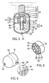
FIG. 2 is a cross-sectional view of the present invention; -
FIG. 3 is an enlarged view of the heat dissipating body of this invention; -
FIG. 4 is a view showing the transparent casing of this invention; -
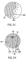
FIG. 5A is a view illustrating the first installation method with a light guiding element of this invention; -
FIG. 5B is an enlarged view inFIG. 5A showing the first preferred embodiment of the light guiding element in this invention; -
FIG. 5C is an enlarged view of a selected portion inFIG. 5B ; -
FIG. 5D is an enlarged view inFIG. 5A showing the second preferred embodiment of the light guiding element in this invention; -
FIG. 6A is a view illustrating the first installation method with a light diffuser of this invention; -
FIG. 6B an enlarged view inFIG. 6A showing the first preferred embodiment of the light diffuser in this invention; -
FIG. 6C an enlarged view inFIG. 6A showing the second preferred embodiment of the light diffuser in this invention; -
FIG. 7 is a view illustrating the second installation method of this invention. -
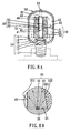
FIG 8A is a view illustrating the second installation method with a light guiding element in this invention; -
FIG. 8B is an enlarged view showing the first example of the light guiding element in this invention; -
FIG. 8C is an enlarged view of a selected portion inFIG. 8B ; -
FIG. 8D is an enlarged view showing the second example of the light guiding element in this invention; -
FIG. 9A is a view illustrating the second installation method with a light diffuser in this invention; -
FIG. 9B is an enlarged view illustrating the first example of the light diffuser in this invention; -
FIG. 9C is an enlarged view illustrating the second example of the light diffuser in this invention; -
FIG. 10 is a perspective view of another embodiment of the central venting portion to be disposed in the inner passage of the heat dissipating body in this invention; -
FIG. 11 is a perspective view of the first traditional light emitting diode illuminating device; and -
FIG. 12 is a perspective view of the second traditional light emitting diode illuminating device. -
FIGS. 1 and2 show the first preferred embodiment of the present invention. This invention is a high efficiency light emitting diode apparatus. It mainly comprises aconnector 10, aheat dissipating body 20, alight generator 30, acentral venting portion 40, and atransparent casing 50. - Concerning this
connector 10, it has an electric connectingportion 11, anelectrical processor 12, aflow guider 13 and a connectinghousing 14. Theelectrical processor 12 is connected with theelectric connector 11. Theflow guider 13 is disposed at an end opposite to theelectric processor 12. The connectinghousing 14 is disposed on an outer edge of thiselectrical processor 12. Further, the connectinghousing 14 has an inner side that forms anair guiding chamber 15. In addition, the connectinghousing 14 has at least onevent 16. - The heat dissipating body 20 (as shown in
FIG. 3 ) is disposed on one end of theconnector 10. Theheat dissipating body 20 has a working surface 21 (that is at one side of the heat dissipating body 20), aninner passage 22, and at least oneouter passage 23. Thisinner passage 22 is internally formed in theheat dissipating body 20. Theouter passages 23 are distributed around theinner passage 22. - With regard to the
light generator 30, it contains several light emitting diodes (LED) 31 distributed as a ring-shaped arrangement. Thelight generator 30 is secured on the working surface 21 (as exhibited inFIG. 3 ). Thislight generator 30 is powered by theelectrical processor 12. - About this
central venting portion 40, it is disposed on an open end of theheat dissipating body 20. Thecentral venting portion 40 has afirst end 41, asecond end 42, and at least onecentral channel 43. Moreover, thefirst end 41 is mounted on theheat dissipating body 20. Thecentral channel 43 communicates with theinner passage 22 so that a through hole is formed. - Concerning the transparent casing 50 (see
FIG. 4 ), it has a securingflange 51, astorage space 52, and anair hole 53. The securingflange 51 is connected with one end of theheat dissipating body 20. Thestorage space 52 has a hollow interior. Further, theair hole 53 penetrates through thetransparent casing 50. Thestorage space 52 is provided for allowing thecentral venting portion 40 can be positioned therein. - Therefore, an inner flow path W1 and several outer flow paths W2 are formed between the
vent 16 and theair hole 53. The inner flow path W1 is consisted of theair hole 53, thecentral channel 43, saidinner passage 22, theflow guider 13, and saidvent 16. The outer flow path W2 is consisted of theair hole 53, thestorage space 52, theouter passages 23, theflow chamber 15, and thevent 16. - Practically, the
flow guider 13 could be conical (as shown inFIGS. 5A and8A ) or flat (as shown inFIGS. 6A and9A ). When theflow guider 13 is a flat structure, it can further include a non-electricity-driven fan 131 (as shown inFIG. 6A ).The fan 131 can be driven by natural convection without any power. - In addition, the
inner passage 22 can be a circular passage or a polygonal passage (as shown inFIG. 10 ). Of course, one or morecentral venting portions 40 can be installed in thisinner passage 22. - In order to enhance the illuminating effect, the
light generator 30 can further include alight guiding element 32 or alight diffuser 33. Or, it can include both. - With regard to the light guiding element 32 (as shown in
FIGS. 5A and8A ), it includes aninside surface 321 and anoutside surface 322. Theouter surface 322 is sloped with a preset tapered angle and is disposed with a plurality of optical microstructures 323 (as illustrated inFIGS. 5B ,5C ,8B and8C ). Thelight guiding element 32 may contact with the outer surface of the light emitting diodes 31 (as shown inFIGS. 5B &8B ) or may enclose the light emitting diodes 31 (as shown inFIGS. 5D &8D ). Because thelight guiding element 32 contacts with thelight emitting diodes 31, not only the light of thelight emitting diodes 31 can be transmitted, but also the heat generated by thelight emitting diodes 31 can be transferred so as to dissipate the heat of thelight emitting diodes 31. - Next, the function of the
light diffuser 33 is provided to diffuse the light uniformly (as shown inFIGS. 6A, 6B ,9A and 9B ). Thelight diffuser 33 may contact with the outer surface of the light emitting diodes 31 (as shown inFIGS. 6B &9B ) or may enclose the light emitting diodes 31 (as shown inFIGS. 6C &9C ). Because thelight diffuser 33 contacts with thelight emitting diodes 31, not only the light of thelight emitting diodes 31 can be transmitted, but also the heat generated by thelight emitting diodes 31 can be transferred to thelight diffuser 33 so as to dissipate the heat of thelight emitting diodes 31. - The surface of the
central venting portion 40 can further include a reflectingportion 44 so as to reflect light. - A plurality of optical microstructures may be added on the
transparent casing 50 for having better illumination (more uniformly). Also, a plurality of micro holes (as illustrated inFIG. 4 , the diameter of the micro hole is less than the wavelength of the light) can be formed on thetransparent casing 50. Under this circumstance, when the light passing through thesemicrostructures 54, a diffraction effect is occurred and the light emits more uniformly. - Moreover, about the installation method of this invention, the
connector 10 can be faced upward and thetransparent casing 50 is faced downward so that this invention can be installed on a predetermined position (seeFIG. 2 , such as on the ceiling), Or, it can be upside down (connector 10 facing downward and thetransparent casing 50 facing upward, such as installing on the ground for illumination and guiding). Anyway, it can be installed at a tilted condition as well, if needed. - After turning on the
light emitting diodes 31, thelight emitting diodes 31 generate heat (at a relative high temperature). Theheat dissipating body 20 behind thelight emitting diodes 31 transmits a lot of heat away quickly. Meanwhile, the light guiding element 32 (or light diffuser 33) transmits certain heat away. - When the heat accumulates inside the
transparent casing 50, its temperature is raised. The external cold air is sucked in via the air hole 53 (seeFIG. 2 ). Two air streams are formed, namely, the inner flow path W1 (consisted of theair hole 53, thecentral channel 43, theinner passage 22, theflow guider 13, and saidvent 16.) and several outer flow paths W2 (consisted of theair hole 53, thestorage space 52, theouter passages 23, theflow chamber 15, and the vent 16). Thus, the heat can be removed by these air streams quickly so that thelight emitting diodes 31 will not be overheated during a long-term use. - If this invention is installed upside down, the function remains unchanged. But, the flowing direction is just opposite to the previous one. The external cold air is sucked via the vent 16 (see
FIG. 8A ) so as to form two air streams, namely, the inner flow path W1 (consisted of theair hole 53, thecentral channel 43, saidinner passage 22, theflow guider 13, and saidvent 16.) and several outer flow paths W2 (consisted of theair hole 53, thestorage space 52, theouter passages 23, theflow chamber 15, and the vent 16). Similarly, the heat can be expelled by these air streams quickly. - Therefore, the advantages and functions of the present invention can be summarized as follows.
- [1] The heat dissipating effect of the flow paths is excellent. Except the heat dissipation of the heat dissipating body, the inner and outer flow paths bring a lot of heat away due to natural convection. The heat generated by the light emitting diodes will be taken way by the flowing air significantly. Thus, the heat dissipating effect is excellent.
- [2] The structure forming two flow paths can enhance the heat dissipating effect. In this invention, it contains both the inner and outer flow paths. No matter this invention is installed at a regular position or upside down, the cold external air can enter the interior of this invention. The cooling air automatically separates into an inner one and an outer one due to the natural convection without any power. These two flow paths generate a good heat dissipating effect.
- [3] The auxiliary element can strengthen the overall illuminating effect. By utilizing the light diffuser and/or the light guiding element, the light can be transmitted brighter. Hence, the illumination effect is strengthened.
- [4] The auxiliary element can make the light more uniformly. Once the microstructure (such as the micro holes) is applied, the light will become more uniformly.
- While this invention has been particularly shown and described with references to the preferred embodiments thereof, it will be understood by those skilled in the art that various changes or modifications can be made therein without departing from the scope of the invention by the appended claims.
Claims (10)
- A high efficiency light emitting diode apparatus comprising:a connector (10) having an electric connecting portion (11), an electrical processor (12), a flow guider (13) and a connecting housing (14), said electrical processor (12) being connected with said electric connector (10), said flow guider (13) being disposed at an end opposite to said electric processor (12), said connecting housing (14) being disposed on an outer edge of said electrical processor (12); said connecting housing (14) having an inner side that forms an air guiding chamber (15), and said connecting housing (14) having at least one vent (16);a heat dissipating body (20) disposed on one end of said connector (10), said heat dissipating body (20) having a working surface (21), an inner passage (22) and at least one outer passage (23), said inner passage (22) being internally formed in said heat dissipating body (20), said at least one outer passage (23) being distributed around said inner passage (22);a light generator (30) containing several light emitting diodes (31) distributed as a ring-shaped arrangement, said light generator (30) being secured on said working surface (21), said light generator (30) being powered by said electrical processor (12);a central venting portion (40) disposed on an open end of said heat dissipating body (20), said central venting portion (40) having a first end (41), a second end (42), and at least one central channel (43), said first end being (41) mounted on said heat dissipating body (20), said central channel (43) communicating with said inner passage (22) so as to form a through hole; anda transparent casing (50) having a securing flange (51), a storage space (52), and an air hole (53), said securing flange (51) being connected with one end of said heat dissipating body (20), said storage space (52) having a hollow interior, said air hole (53) penetrating through said transparent casing (50), said storage space (52) allowing said central venting portion (40) being positioned therein;wherein an inner flow path and several outer flow paths are formed between said vent (16) and said air hole (53), said inner flow path being consisted of said air hole (53), said central channel (43), said inner passage (22), said flow guider (13), and said vent (16); said outer flow path being consisted of said air hole (53), said storage space (52), said outer passage (23), said flow chamber (15), and said vent (16).
- The high efficiency light emitting diode apparatus of claim 1, wherein said flow guider (13) is conical or flat.
- The high efficiency light emitting diode apparatus of claim 2, wherein said flow guider (13) further includes a non-electricity-driven fan (131).
- The high efficiency light emitting diode apparatus of claim 1, wherein said inner passage (22) is a circular passage or a polygonal passage.
- The high efficiency light emitting diode apparatus of claim 4, wherein one or more central venting portions (40) are installed in said inner passage (22).
- The high efficiency light emitting diode apparatus of claim 1, wherein said light generator (30) further comprises:a light guiding element (32) having an inside surface (321) and an outside surface (322); said outer surface (322) having a preset tapered angle and a plurality of optical microstructures (323).
- The high efficiency light emitting diode apparatus of claim 1, wherein said light generator further (30) comprises:a light diffuser (33) for diffusing the light uniformly.
- The high efficiency light emitting diode apparatus of claim 1, wherein a surface of the central venting portion (40) has a reflecting portion (44).
- The high efficiency light emitting diode apparatus of claim 1, wherein the transparent casing (50) comprises a plurality of optical microstructures (54) or micro holes.
- The high efficiency light emitting diode apparatus of claim 1, wherein said light guiding element (32) contacts with or encloses the outer surface of the light emitting diodes (31).
Applications Claiming Priority (1)
| Application Number | Priority Date | Filing Date | Title |
|---|---|---|---|
| TW098105583A TW201031859A (en) | 2009-02-23 | 2009-02-23 | High efficiency luminous body |
Publications (2)
| Publication Number | Publication Date |
|---|---|
| EP2221523A1 EP2221523A1 (en) | 2010-08-25 |
| EP2221523B1 true EP2221523B1 (en) | 2011-10-26 |
Family
ID=42235760
Family Applications (1)
| Application Number | Title | Priority Date | Filing Date |
|---|---|---|---|
| EP09157986A Not-in-force EP2221523B1 (en) | 2009-02-23 | 2009-04-15 | High efficiency light emitting diode apparatus |
Country Status (5)
| Country | Link |
|---|---|
| US (1) | US7950829B2 (en) |
| EP (1) | EP2221523B1 (en) |
| JP (1) | JP4932868B2 (en) |
| AT (1) | ATE530847T1 (en) |
| TW (1) | TW201031859A (en) |
Families Citing this family (40)
| Publication number | Priority date | Publication date | Assignee | Title |
|---|---|---|---|---|
| US8596825B2 (en) * | 2009-08-04 | 2013-12-03 | 3M Innovative Properties Company | Solid state light with optical guide and integrated thermal guide |
| US8157419B2 (en) * | 2009-08-26 | 2012-04-17 | Abl Ip Holding Llc | LED assembly |
| JP5354209B2 (en) * | 2010-01-14 | 2013-11-27 | 東芝ライテック株式会社 | Light bulb shaped lamp and lighting equipment |
| DE102010001047A1 (en) * | 2010-01-20 | 2011-07-21 | Osram Gesellschaft mit beschränkter Haftung, 81543 | lighting device |
| USD660509S1 (en) * | 2010-04-22 | 2012-05-22 | Edison Opto Corporation | LED lamp |
| US8201983B2 (en) * | 2010-06-01 | 2012-06-19 | Young Lighting Technology Inc. | Illuminating device |
| TWI467115B (en) * | 2010-08-06 | 2015-01-01 | Ind Tech Res Inst | Light source apparatus with high heat dissipation efficiency |
| US20130201700A1 (en) * | 2010-11-04 | 2013-08-08 | Panasonic Corporation | Lamp |
| US8487518B2 (en) * | 2010-12-06 | 2013-07-16 | 3M Innovative Properties Company | Solid state light with optical guide and integrated thermal guide |
| CN102588756B (en) * | 2011-01-13 | 2014-05-07 | 光宝电子(广州)有限公司 | Lighting fixture |
| US20120194054A1 (en) * | 2011-02-02 | 2012-08-02 | 3M Innovative Properties Company | Solid state light with optical diffuser and integrated thermal guide |
| WO2012126174A1 (en) * | 2011-03-21 | 2012-09-27 | 上海嘉塘电子有限公司 | Led lighting lamp |
| CN102207252B (en) * | 2011-04-14 | 2013-03-20 | 厦门阳光恩耐照明有限公司 | LED bulb |
| KR20130016940A (en) * | 2011-08-09 | 2013-02-19 | 삼성전자주식회사 | Lighting device |
| US20130051003A1 (en) * | 2011-08-26 | 2013-02-28 | Chenjun Fan | LED Lighting Device with Efficient Heat Removal |
| JP5789164B2 (en) * | 2011-09-30 | 2015-10-07 | 株式会社アイ・ライティング・システム | Lighting device |
| US8992051B2 (en) | 2011-10-06 | 2015-03-31 | Intematix Corporation | Solid-state lamps with improved radial emission and thermal performance |
| US20130088848A1 (en) * | 2011-10-06 | 2013-04-11 | Intematix Corporation | Solid-state lamps with improved radial emission and thermal performance |
| KR101318432B1 (en) * | 2011-11-14 | 2013-10-16 | 아이스파이프 주식회사 | Led lighting apparatus |
| US8931925B2 (en) * | 2012-01-09 | 2015-01-13 | Tai-Her Yang | LED heat dissipation device having axial and radial convection holes |
| WO2013132549A1 (en) * | 2012-03-07 | 2013-09-12 | パナソニック株式会社 | Lamp |
| CN102679212A (en) * | 2012-04-06 | 2012-09-19 | 厦门天力源光电科技有限公司 | Integral LED lamp |
| US8974091B2 (en) * | 2012-08-28 | 2015-03-10 | Liquidleds Lighting Corp. | Heat-dissipating structure for an LED lamp |
| CN103047563A (en) * | 2012-11-30 | 2013-04-17 | 黄超 | Light-emitting diode (LED) lamp provided with air convection channels distributed between light sources |
| US9303821B2 (en) * | 2013-03-29 | 2016-04-05 | Uniled Lighting Tw., Inc. | Air-cooled LED lamp bulb |
| US9068732B2 (en) * | 2013-03-29 | 2015-06-30 | Uniled Lighting Tw., Inc | Air-cooled LED lamp bulb |
| CN103256582B (en) * | 2013-05-22 | 2015-04-22 | 北京铨富光电科技有限公司 | Gas heat convection heat dissipating structure of LED bulb |
| US9249964B2 (en) * | 2014-01-08 | 2016-02-02 | Zweibruder Optoelectronics Gmbh & Co. Kg | Multi-purpose illumination device |
| EP3102011A4 (en) * | 2014-01-27 | 2017-03-08 | Shanghai Sansi Electronics Engineering Co., Ltd. | Led lighting apparatus, light shade, and circuit manufacturing method for the apparatus |
| CN103791439B (en) * | 2014-01-27 | 2015-05-06 | 上海三思电子工程有限公司 | Novel LED lighting device |
| JP6495307B2 (en) * | 2014-01-27 | 2019-04-03 | 上海三思▲電▼子工程有限公司Shanghai Sansi Electronic Engineering Co.,Ltd. | LED lighting device |
| US9464802B2 (en) * | 2014-02-19 | 2016-10-11 | Ozyegin Universitesi | Flow controlled effective LED based lighting system |
| US20170138562A1 (en) * | 2014-06-12 | 2017-05-18 | Westland Joaus Technologies, Llc | System, devices, and methods for illumination including solid-state light emitting devices |
| JP3203081U (en) * | 2015-02-04 | 2016-03-10 | 嘉▲興▼山蒲照明▲電▼器有限公司Jiaxing Super Lighting Electric Appliance Co.,Ltd | Light bulb shaped LED lamp |
| CN205037120U (en) * | 2015-08-21 | 2016-02-17 | 全亿大科技(佛山)有限公司 | Light emitting diode (LED) lamp |
| WO2018034628A1 (en) * | 2016-08-19 | 2018-02-22 | Ozyegin Universitesi | Flow cooled solid state lighting with preferred optical and advanced sensing features |
| CN107806578B (en) * | 2016-09-06 | 2024-05-28 | 中国科学院苏州纳米技术与纳米仿生研究所 | Semiconductor light-emitting device with air duct structure |
| CN108895417B (en) * | 2018-05-24 | 2020-06-23 | 东莞市闻誉实业有限公司 | Cylinder type radiator |
| CN113237041A (en) * | 2021-05-27 | 2021-08-10 | 宝德照明集团有限公司 | Explosion-proof energy-saving LED lamp |
| US12085268B2 (en) * | 2022-11-01 | 2024-09-10 | Shanghai Sansi Electronic Engineering Co. Ltd. | Heat sink, separator, and lighting device applying same |
Family Cites Families (13)
| Publication number | Priority date | Publication date | Assignee | Title |
|---|---|---|---|---|
| JPH0463162A (en) * | 1990-06-29 | 1992-02-28 | Suzuki Motor Corp | Coating device |
| US6511209B1 (en) * | 2001-10-02 | 2003-01-28 | Albert C. L. Chiang | Lighting fixture |
| EP1466505B1 (en) * | 2002-01-10 | 2012-08-01 | Osram Ag | Lamp |
| JP2004296245A (en) * | 2003-03-26 | 2004-10-21 | Matsushita Electric Works Ltd | Led lamp |
| GB2417790B (en) * | 2004-09-07 | 2006-11-08 | Set Europ Ltd | Lighting system |
| US7144140B2 (en) * | 2005-02-25 | 2006-12-05 | Tsung-Ting Sun | Heat dissipating apparatus for lighting utility |
| JP2007194132A (en) * | 2006-01-20 | 2007-08-02 | Fujifilm Holdings Corp | Lighting device |
| US7922359B2 (en) * | 2006-07-17 | 2011-04-12 | Liquidleds Lighting Corp. | Liquid-filled LED lamp with heat dissipation means |
| JP2008034140A (en) * | 2006-07-26 | 2008-02-14 | Atex Co Ltd | LED lighting device |
| JP4840185B2 (en) * | 2007-02-17 | 2011-12-21 | 日亜化学工業株式会社 | Lighting device |
| US7651245B2 (en) * | 2007-06-13 | 2010-01-26 | Electraled, Inc. | LED light fixture with internal power supply |
| CN101368719B (en) * | 2007-08-13 | 2011-07-06 | 太一节能系统股份有限公司 | LED lamps |
| JP2010135181A (en) * | 2008-12-04 | 2010-06-17 | Sharp Corp | Illuminating device |
-
2009
- 2009-02-23 TW TW098105583A patent/TW201031859A/en unknown
- 2009-04-06 JP JP2009091708A patent/JP4932868B2/en not_active Expired - Fee Related
- 2009-04-09 US US12/421,114 patent/US7950829B2/en active Active
- 2009-04-15 AT AT09157986T patent/ATE530847T1/en active
- 2009-04-15 EP EP09157986A patent/EP2221523B1/en not_active Not-in-force
Also Published As
| Publication number | Publication date |
|---|---|
| TW201031859A (en) | 2010-09-01 |
| US20100214781A1 (en) | 2010-08-26 |
| TWI361260B (en) | 2012-04-01 |
| US7950829B2 (en) | 2011-05-31 |
| ATE530847T1 (en) | 2011-11-15 |
| JP2010199049A (en) | 2010-09-09 |
| EP2221523A1 (en) | 2010-08-25 |
| JP4932868B2 (en) | 2012-05-16 |
Similar Documents
| Publication | Publication Date | Title |
|---|---|---|
| US7950829B2 (en) | High efficiency light emitting diode apparatus | |
| CN103069213B (en) | Light emitting device with different light transmission areas | |
| JP4989170B2 (en) | Compact LED lamp | |
| EP2021688B1 (en) | Lighting device | |
| CN101641550B (en) | Light-emitting diode (LED)-based lighting systems | |
| EP2295853B1 (en) | Light Emitting Diode Lamp Structure | |
| JP5296122B2 (en) | Lighting device | |
| US8696163B2 (en) | Lamp with wide-angle light emission and bulb thereof | |
| CN101813242A (en) | high-efficiency illuminant | |
| CA2800579A1 (en) | Heat dissipater with axial and radial air aperture and application device thereof | |
| US7911119B2 (en) | Heat dissipating device having turbine ventilator and LED lamp comprising the same | |
| CN102308147A (en) | Cooling element for a lighting device | |
| JP4987141B2 (en) | LED bulb | |
| JP4989671B2 (en) | Lighting device | |
| JP2015125871A (en) | Lighting device | |
| KR102275357B1 (en) | A LED Module device that is including on heat-pipes | |
| KR20100106778A (en) | Led electric bulb | |
| TWI784587B (en) | Fishing luminaire | |
| TWM436134U (en) | Light emitting device and lampshade thereof | |
| JP2011228286A (en) | Lighting device | |
| US20110273890A1 (en) | Ventilated led optics | |
| KR200454488Y1 (en) | Lighting equipment | |
| TW201113467A (en) | Reduced size LED luminaire | |
| US20110222305A1 (en) | Led car lamp structure with demisting and dehumidify functions | |
| TWM619954U (en) | Fishing luminaire |
Legal Events
| Date | Code | Title | Description |
|---|---|---|---|
| PUAI | Public reference made under article 153(3) epc to a published international application that has entered the european phase |
Free format text: ORIGINAL CODE: 0009012 |
|
| 17P | Request for examination filed |
Effective date: 20090427 |
|
| AK | Designated contracting states |
Kind code of ref document: A1 Designated state(s): AT BE BG CH CY CZ DE DK EE ES FI FR GB GR HR HU IE IS IT LI LT LU LV MC MK MT NL NO PL PT RO SE SI SK TR |
|
| AX | Request for extension of the european patent |
Extension state: AL BA RS |
|
| GRAP | Despatch of communication of intention to grant a patent |
Free format text: ORIGINAL CODE: EPIDOSNIGR1 |
|
| RIC1 | Information provided on ipc code assigned before grant |
Ipc: F21V 29/00 20060101ALN20110510BHEP Ipc: F21V 29/02 20060101ALN20110510BHEP Ipc: F21Y 101/02 20060101ALN20110510BHEP Ipc: F21K 99/00 20100101AFI20110510BHEP |
|
| GRAS | Grant fee paid |
Free format text: ORIGINAL CODE: EPIDOSNIGR3 |
|
| GRAA | (expected) grant |
Free format text: ORIGINAL CODE: 0009210 |
|
| AK | Designated contracting states |
Kind code of ref document: B1 Designated state(s): AT BE BG CH CY CZ DE DK EE ES FI FR GB GR HR HU IE IS IT LI LT LU LV MC MK MT NL NO PL PT RO SE SI SK TR |
|
| REG | Reference to a national code |
Ref country code: GB Ref legal event code: FG4D |
|
| REG | Reference to a national code |
Ref country code: CH Ref legal event code: EP |
|
| REG | Reference to a national code |
Ref country code: IE Ref legal event code: FG4D |
|
| REG | Reference to a national code |
Ref country code: DE Ref legal event code: R096 Ref document number: 602009003254 Country of ref document: DE Effective date: 20111222 |
|
| REG | Reference to a national code |
Ref country code: NL Ref legal event code: VDEP Effective date: 20111026 |
|
| LTIE | Lt: invalidation of european patent or patent extension |
Effective date: 20111026 |
|
| PG25 | Lapsed in a contracting state [announced via postgrant information from national office to epo] |
Ref country code: NO Free format text: LAPSE BECAUSE OF FAILURE TO SUBMIT A TRANSLATION OF THE DESCRIPTION OR TO PAY THE FEE WITHIN THE PRESCRIBED TIME-LIMIT Effective date: 20120126 Ref country code: BE Free format text: LAPSE BECAUSE OF FAILURE TO SUBMIT A TRANSLATION OF THE DESCRIPTION OR TO PAY THE FEE WITHIN THE PRESCRIBED TIME-LIMIT Effective date: 20111026 Ref country code: IS Free format text: LAPSE BECAUSE OF FAILURE TO SUBMIT A TRANSLATION OF THE DESCRIPTION OR TO PAY THE FEE WITHIN THE PRESCRIBED TIME-LIMIT Effective date: 20120226 Ref country code: LT Free format text: LAPSE BECAUSE OF FAILURE TO SUBMIT A TRANSLATION OF THE DESCRIPTION OR TO PAY THE FEE WITHIN THE PRESCRIBED TIME-LIMIT Effective date: 20111026 |
|
| PG25 | Lapsed in a contracting state [announced via postgrant information from national office to epo] |
Ref country code: SE Free format text: LAPSE BECAUSE OF FAILURE TO SUBMIT A TRANSLATION OF THE DESCRIPTION OR TO PAY THE FEE WITHIN THE PRESCRIBED TIME-LIMIT Effective date: 20111026 Ref country code: LV Free format text: LAPSE BECAUSE OF FAILURE TO SUBMIT A TRANSLATION OF THE DESCRIPTION OR TO PAY THE FEE WITHIN THE PRESCRIBED TIME-LIMIT Effective date: 20111026 Ref country code: SI Free format text: LAPSE BECAUSE OF FAILURE TO SUBMIT A TRANSLATION OF THE DESCRIPTION OR TO PAY THE FEE WITHIN THE PRESCRIBED TIME-LIMIT Effective date: 20111026 Ref country code: GR Free format text: LAPSE BECAUSE OF FAILURE TO SUBMIT A TRANSLATION OF THE DESCRIPTION OR TO PAY THE FEE WITHIN THE PRESCRIBED TIME-LIMIT Effective date: 20120127 Ref country code: NL Free format text: LAPSE BECAUSE OF FAILURE TO SUBMIT A TRANSLATION OF THE DESCRIPTION OR TO PAY THE FEE WITHIN THE PRESCRIBED TIME-LIMIT Effective date: 20111026 Ref country code: HR Free format text: LAPSE BECAUSE OF FAILURE TO SUBMIT A TRANSLATION OF THE DESCRIPTION OR TO PAY THE FEE WITHIN THE PRESCRIBED TIME-LIMIT Effective date: 20111026 Ref country code: PL Free format text: LAPSE BECAUSE OF FAILURE TO SUBMIT A TRANSLATION OF THE DESCRIPTION OR TO PAY THE FEE WITHIN THE PRESCRIBED TIME-LIMIT Effective date: 20111026 Ref country code: PT Free format text: LAPSE BECAUSE OF FAILURE TO SUBMIT A TRANSLATION OF THE DESCRIPTION OR TO PAY THE FEE WITHIN THE PRESCRIBED TIME-LIMIT Effective date: 20120227 |
|
| PG25 | Lapsed in a contracting state [announced via postgrant information from national office to epo] |
Ref country code: CY Free format text: LAPSE BECAUSE OF FAILURE TO SUBMIT A TRANSLATION OF THE DESCRIPTION OR TO PAY THE FEE WITHIN THE PRESCRIBED TIME-LIMIT Effective date: 20111026 |
|
| PG25 | Lapsed in a contracting state [announced via postgrant information from national office to epo] |
Ref country code: EE Free format text: LAPSE BECAUSE OF FAILURE TO SUBMIT A TRANSLATION OF THE DESCRIPTION OR TO PAY THE FEE WITHIN THE PRESCRIBED TIME-LIMIT Effective date: 20111026 Ref country code: CZ Free format text: LAPSE BECAUSE OF FAILURE TO SUBMIT A TRANSLATION OF THE DESCRIPTION OR TO PAY THE FEE WITHIN THE PRESCRIBED TIME-LIMIT Effective date: 20111026 Ref country code: DK Free format text: LAPSE BECAUSE OF FAILURE TO SUBMIT A TRANSLATION OF THE DESCRIPTION OR TO PAY THE FEE WITHIN THE PRESCRIBED TIME-LIMIT Effective date: 20111026 Ref country code: BG Free format text: LAPSE BECAUSE OF FAILURE TO SUBMIT A TRANSLATION OF THE DESCRIPTION OR TO PAY THE FEE WITHIN THE PRESCRIBED TIME-LIMIT Effective date: 20120126 Ref country code: SK Free format text: LAPSE BECAUSE OF FAILURE TO SUBMIT A TRANSLATION OF THE DESCRIPTION OR TO PAY THE FEE WITHIN THE PRESCRIBED TIME-LIMIT Effective date: 20111026 |
|
| PG25 | Lapsed in a contracting state [announced via postgrant information from national office to epo] |
Ref country code: IT Free format text: LAPSE BECAUSE OF FAILURE TO SUBMIT A TRANSLATION OF THE DESCRIPTION OR TO PAY THE FEE WITHIN THE PRESCRIBED TIME-LIMIT Effective date: 20111026 Ref country code: RO Free format text: LAPSE BECAUSE OF FAILURE TO SUBMIT A TRANSLATION OF THE DESCRIPTION OR TO PAY THE FEE WITHIN THE PRESCRIBED TIME-LIMIT Effective date: 20111026 |
|
| PLBE | No opposition filed within time limit |
Free format text: ORIGINAL CODE: 0009261 |
|
| STAA | Information on the status of an ep patent application or granted ep patent |
Free format text: STATUS: NO OPPOSITION FILED WITHIN TIME LIMIT |
|
| 26N | No opposition filed |
Effective date: 20120727 |
|
| REG | Reference to a national code |
Ref country code: DE Ref legal event code: R097 Ref document number: 602009003254 Country of ref document: DE Effective date: 20120727 |
|
| PG25 | Lapsed in a contracting state [announced via postgrant information from national office to epo] |
Ref country code: MC Free format text: LAPSE BECAUSE OF NON-PAYMENT OF DUE FEES Effective date: 20120430 |
|
| REG | Reference to a national code |
Ref country code: IE Ref legal event code: MM4A |
|
| PG25 | Lapsed in a contracting state [announced via postgrant information from national office to epo] |
Ref country code: IE Free format text: LAPSE BECAUSE OF NON-PAYMENT OF DUE FEES Effective date: 20120415 |
|
| PG25 | Lapsed in a contracting state [announced via postgrant information from national office to epo] |
Ref country code: MK Free format text: LAPSE BECAUSE OF FAILURE TO SUBMIT A TRANSLATION OF THE DESCRIPTION OR TO PAY THE FEE WITHIN THE PRESCRIBED TIME-LIMIT Effective date: 20111026 |
|
| PG25 | Lapsed in a contracting state [announced via postgrant information from national office to epo] |
Ref country code: ES Free format text: LAPSE BECAUSE OF FAILURE TO SUBMIT A TRANSLATION OF THE DESCRIPTION OR TO PAY THE FEE WITHIN THE PRESCRIBED TIME-LIMIT Effective date: 20120206 |
|
| PG25 | Lapsed in a contracting state [announced via postgrant information from national office to epo] |
Ref country code: FI Free format text: LAPSE BECAUSE OF FAILURE TO SUBMIT A TRANSLATION OF THE DESCRIPTION OR TO PAY THE FEE WITHIN THE PRESCRIBED TIME-LIMIT Effective date: 20111026 |
|
| PG25 | Lapsed in a contracting state [announced via postgrant information from national office to epo] |
Ref country code: MT Free format text: LAPSE BECAUSE OF FAILURE TO SUBMIT A TRANSLATION OF THE DESCRIPTION OR TO PAY THE FEE WITHIN THE PRESCRIBED TIME-LIMIT Effective date: 20111026 |
|
| PG25 | Lapsed in a contracting state [announced via postgrant information from national office to epo] |
Ref country code: TR Free format text: LAPSE BECAUSE OF FAILURE TO SUBMIT A TRANSLATION OF THE DESCRIPTION OR TO PAY THE FEE WITHIN THE PRESCRIBED TIME-LIMIT Effective date: 20111026 |
|
| PG25 | Lapsed in a contracting state [announced via postgrant information from national office to epo] |
Ref country code: LU Free format text: LAPSE BECAUSE OF NON-PAYMENT OF DUE FEES Effective date: 20120415 |
|
| PG25 | Lapsed in a contracting state [announced via postgrant information from national office to epo] |
Ref country code: HU Free format text: LAPSE BECAUSE OF FAILURE TO SUBMIT A TRANSLATION OF THE DESCRIPTION OR TO PAY THE FEE WITHIN THE PRESCRIBED TIME-LIMIT Effective date: 20090415 |
|
| REG | Reference to a national code |
Ref country code: FR Ref legal event code: PLFP Year of fee payment: 8 |
|
| PGFP | Annual fee paid to national office [announced via postgrant information from national office to epo] |
Ref country code: CH Payment date: 20160420 Year of fee payment: 8 Ref country code: GB Payment date: 20160421 Year of fee payment: 8 Ref country code: DE Payment date: 20160421 Year of fee payment: 8 |
|
| PGFP | Annual fee paid to national office [announced via postgrant information from national office to epo] |
Ref country code: AT Payment date: 20160421 Year of fee payment: 8 Ref country code: FR Payment date: 20160421 Year of fee payment: 8 |
|
| REG | Reference to a national code |
Ref country code: DE Ref legal event code: R119 Ref document number: 602009003254 Country of ref document: DE |
|
| REG | Reference to a national code |
Ref country code: CH Ref legal event code: PL |
|
| REG | Reference to a national code |
Ref country code: AT Ref legal event code: MM01 Ref document number: 530847 Country of ref document: AT Kind code of ref document: T Effective date: 20170415 |
|
| GBPC | Gb: european patent ceased through non-payment of renewal fee |
Effective date: 20170415 |
|
| REG | Reference to a national code |
Ref country code: FR Ref legal event code: ST Effective date: 20171229 |
|
| PG25 | Lapsed in a contracting state [announced via postgrant information from national office to epo] |
Ref country code: DE Free format text: LAPSE BECAUSE OF NON-PAYMENT OF DUE FEES Effective date: 20171103 Ref country code: FR Free format text: LAPSE BECAUSE OF NON-PAYMENT OF DUE FEES Effective date: 20170502 Ref country code: AT Free format text: LAPSE BECAUSE OF NON-PAYMENT OF DUE FEES Effective date: 20170415 |
|
| PG25 | Lapsed in a contracting state [announced via postgrant information from national office to epo] |
Ref country code: LI Free format text: LAPSE BECAUSE OF NON-PAYMENT OF DUE FEES Effective date: 20170430 Ref country code: CH Free format text: LAPSE BECAUSE OF NON-PAYMENT OF DUE FEES Effective date: 20170430 Ref country code: GB Free format text: LAPSE BECAUSE OF NON-PAYMENT OF DUE FEES Effective date: 20170415 |