EP2220949A1 - Strangschneiden - Google Patents
Strangschneiden Download PDFInfo
- Publication number
- EP2220949A1 EP2220949A1 EP10152474A EP10152474A EP2220949A1 EP 2220949 A1 EP2220949 A1 EP 2220949A1 EP 10152474 A EP10152474 A EP 10152474A EP 10152474 A EP10152474 A EP 10152474A EP 2220949 A1 EP2220949 A1 EP 2220949A1
- Authority
- EP
- European Patent Office
- Prior art keywords
- strand
- circular blade
- circular
- cutting device
- cutting
- Prior art date
- Legal status (The legal status is an assumption and is not a legal conclusion. Google has not performed a legal analysis and makes no representation as to the accuracy of the status listed.)
- Granted
Links
Images


Classifications
-
- A—HUMAN NECESSITIES
- A24—TOBACCO; CIGARS; CIGARETTES; SIMULATED SMOKING DEVICES; SMOKERS' REQUISITES
- A24C—MACHINES FOR MAKING CIGARS OR CIGARETTES
- A24C5/00—Making cigarettes; Making tipping materials for, or attaching filters or mouthpieces to, cigars or cigarettes
- A24C5/14—Machines of the continuous-rod type
- A24C5/28—Cutting-off the tobacco rod
-
- A—HUMAN NECESSITIES
- A24—TOBACCO; CIGARS; CIGARETTES; SIMULATED SMOKING DEVICES; SMOKERS' REQUISITES
- A24C—MACHINES FOR MAKING CIGARS OR CIGARETTES
- A24C5/00—Making cigarettes; Making tipping materials for, or attaching filters or mouthpieces to, cigars or cigarettes
- A24C5/14—Machines of the continuous-rod type
- A24C5/31—Machines of the continuous-rod type with special arrangements coming into operation during starting, slowing-down or breakdown of the machine, e.g. for diverting or breaking the continuous rod
Definitions
- the invention relates to a strand cutting device of the tobacco processing industry with a circular blade which is rotatable about an axis of rotation.
- the invention further relates to a method for cutting at least one strand of the tobacco processing industry, wherein a rotating circular blade is passed through the strand moving in a strand guide path.
- a corresponding strand cutting device is off EP 1 800 551 A2 known.
- the axis of rotation of the circular knife lies transversely to a strand which can be cut by the circular knife, the axis of rotation being arranged substantially horizontally during operation of the strand cutting device, and the strand cutting device being pivoted horizontally via a pivoting arm in order to engage the circular knife with the strand.
- a strand cutting device of the generic type and a corresponding method for cutting a strand of the tobacco processing industry educate such that a safe and fast cut through the strand is possible, the strand during cutting in particular not steered from its path and a clean cut should be possible.
- the strand cutting device according to the invention should also be applicable to machines which process a plurality of strands, in particular two strands.
- a strand cutting device of the tobacco processing industry with a circular blade which is rotatable about an axis of rotation, wherein a circular blade guide device is provided which moves the circular blade in operation linearly.
- the circular knife guide device is preferably designed as a lifting device and / or linear movement device.
- the axis of rotation is arranged substantially horizontally during operation of the strand cutting device.
- the axis of rotation is formed perpendicular to a longitudinal axis of a strand guide track.
- the strand guide path is the path in which the strand moves. In this case, a forced operation does not necessarily have to be provided.
- a strand guideway may also lead over a free distance, especially in air.
- the circular knife guide device calls for movement of the circular knife, which is parallel to the axis of rotation of the circular knife.
- a movement of the circular knife may be made possible, which is substantially perpendicular to a strand guide track or is substantially perpendicular to the movable strand of the tobacco processing industry to be cut through.
- the circular knife guide device may be provided with a hydraulic cylinder that generates the linear movement, or with motors that allow, for example via corresponding gears, the linear movement of the circular blade. In this case, a corresponding stroke for the circular blade is generated by the circular blade guide device, which is sufficiently large to cut through the strand or multiple strands.
- the axis of rotation of the circular blade is arranged transversely, in particular perpendicular, to a strand guide track or of the strand to be cut during operation of the circular blade.
- the circular blade is guided linearly and preferably vertically through the strand.
- a strand guiding device which, in particular from below, is movable, in particular pivotable, or can be moved linearly to a strand or a strand guiding path.
- the strand guiding device may preferably be a kind of extension or supplement of a formatting device, wherein the strand guiding device has corresponding openings through which the strands can be moved. The openings may preferably be aligned with openings of a formatting device.
- the strand guiding device preferably serves as an abutment for the circular blade.
- the strand guiding device preferably has two guide openings, which can receive two mutually parallel and movable strands.
- the circular blade preferably experiences a linear stroke, which is greater than the distance between two parallel strands of the tobacco processing industry or two parallel strand guideways, due to the circular blade guide device.
- the distance is defined in the context of the invention so that the outer sides of the strands are each meant so that the stroke passes over both strands.
- the circular blade preferably has a corrugated or serrated surface at its cutting edge.
- the axis of rotation of the circular blade is at an angle of 85 ° to 90 ° to a movable and to be cut strand of the tobacco processing industry and / or at an angle of 0 ° to 5 ° to the linear movement of the circular blade.
- the 85 ° to 90 ° may also be relative to a corresponding strand guideway. It is preferred if the angle of the axis of rotation of the circular blade to the strand guide track or the strand is at 90 ° or is exactly 90 °. This then leads to relatively long diagonal cuts in the strand. To shorten this cut, especially at high strand speeds, the circular blade can be adjusted by a few degrees, so that the cut is improved at high strand speeds.
- a control which adjusts the corresponding angle of the circular blade to the strand guide track as a function of the strand speed.
- the circular blade is preferably rotated at a rotational speed of 1,000 to 3,000 revolutions per minute, more preferably at 2,000 revolutions per minute.
- the strand speed is usually in the range of 50 to 100 meters per minute, and the interface has a length of 12 to 20 mm.
- a rod making machine of the tobacco processing industry with a strand cutting device according to the invention for cutting at least one strand of the tobacco processing industry, wherein for starting the strand machine, the strand cutting device is arranged in a different position than strand-producing operation of the stranding machine, wherein between the two positions a strand guide path is arranged.
- the two strands or a plurality of strands between the two positions are preferably arranged.
- a very defined and controlled startup and shutdown of the stranding machine allows.
- the stranding machine To start the stranding machine this is driven from a low strand production speed to a high strand production speed, wherein initially the strand is still carried away and thus is not provided for further processing. After reaching a satisfactory strand or a predeterminable speed of the strand, the strand is or will be cut in the case of a two-line machine or a multi-strand machine, the strands with the device according to the invention. Subsequently, the upstream part of the strand, upstream relative to the cut, enters the usual further processing of the stranding machine and is then correspondingly cut into desired lengths and further processed to filter cigarettes, for example.
- the strand may be a filter strand or a cigarette rod.
- the object is further achieved by a method for cutting at least one strand of the tobacco-processing industry, wherein a rotating circular blade is passed through the moving in a strand guide track strand, wherein the circular blade is guided linearly through the strand.
- the linear movement of the circular blade is perpendicular to a strand longitudinal axis. Due to the linear motion, the strand can be cut with a very short stroke, or the strands can be cut with a very short stroke, so that a very fast cut is possible.
- the device is then also very compact.
- an angle between the axis of rotation and the strand longitudinal axis may be provided, which is not equal to 90 °.
- the axis of rotation is preferably formed pivotable with respect to its angle to the strand longitudinal axis.
- linear movement of the circular blade is parallel to an axis of rotation of the circular blade.
- the strand is guided in a strand guiding device, which serves as an abutment.
- the strand guiding device for cutting the strand to the strand in particular upwards, moves, in particular pivoted or moved linearly.
- a method for the controlled shutdown of an operating strand machine wherein in the presence of a stop signal, an inventive method for cutting at least one strand of the tobacco processing industry is performed.
- the stop signal may in this case be an automatically generated signal of the strand machine, for example if a strand burst was detected or else a signal which is triggered by an operator.
- Method is for the first time possible to perform a controlled shutdown of an operating strand machine so that defined strand material is cut and defined further processing steps on the cut strand material, which is downstream of the cut, can be performed.
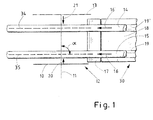
- Fig. 1 schematically shows a plan view of a part of a strand machine 30. It is a double-strand machine, for example, a double filter strand machine. Correspondingly, two filter strands 14 and 15 are shown, which move in the conveying direction 16 or 16 '. This may be strands 14 and 15 covered with a wrapping material. The wrapping and shaping of the filter strands 14 and 15 is done in a format of which the sub-format 18 is shown here. There are also corresponding strand guideways 19 and 19 ⁇ shown in which the strands 14 and 15 are guided. These are in the area of the lower format 18 to appropriately trained tracks.
- the strand guide tracks 19 and 19 'according to the invention are thus in particular a track in which a corresponding strand is arranged or moved. This can also be at least partially without a fixed limit.
- a circular blade 10 indicated that rotates about the axis of rotation 11.
- the circular blade may be corrugated or serrated at its cutting edge.
- Fig. 1 for illustration below the position "start" 12 place for an operator and above the position "operation” 13 a part of the strand machine.
- Fig. 1 In the upper area of Fig. 1 , ie above the position 13, for example, motors, gears, etc. are arranged in the strand machine.
- the circular blade 10 is located in Fig. 1 in position 12, ie in the position start.
- the axis of rotation 11 is perpendicular to the longitudinal axes 34, 35 of the strands 14 and 15.
- the angle ⁇ has an amount of 90 °.
- the blade 10 is moved from the "operating" position 13 in the circular blade movement direction 21 through the strands 14 and 15 and cuts the strands 14 and 15, respectively.
- the upstream portions of the strands 14 and 15 relative to that cut then become excluded from further processing, whereas the downstream parts of this cut can be further processed. This happens, as far as any intended sensors do not recognize that these parts of the strands are no longer suitable for further processing.
- a strand guiding device 17 which has two openings 25 and 26 for guiding the strands 14, 15.
- the openings 25, 26 are in the Figures 2 and 3 better to recognize.
- the strand guiding device 17 is pivoted from below the strands for cutting the strands thereto. This too is in the Figures 2 and 3 better to recognize.
- FIG. 2 3 shows a schematic representation of a strand cutting device 22 according to the invention which has a housing 23 and the circular blade 10. It is shown in FIG Fig. 2 the strand guiding device 17 with the two openings 25 and 26 shown. The strand guiding device 17 is in Fig. 2 to the strands 14, 15 and swung in Fig. 3 pivoted away.
- FIG. 2 the operating state of the strand machine is shown when starting, ie the circular blade 10 is in the position 12 from Fig. 1 , This is remote from the machine wall 24, so that the strands 14, 15 are arranged between the circular blade 10 and the machine wall 24. It is also in Fig. 2 and Fig. 3 a lifting device 27 is shown, which allows the linear stroke of the strand cutting device 22 and thus of the circular blade 10.
- Fig. 4 is yet another schematic plan view of a part of a stranding machine shown.
- Fig. 4 shows in comparison to Fig. 1 a circular blade 10, which is opposite the strand guideways 19 and 19 'or in the strand guideways 19 and 19' arranged filter strands 14, 15, which are not shown, with the strand longitudinal axes 34, 35, which are also not shown, inclined.
- an angle ⁇ which may be between 0 ° and 5 °. In particular, at low speeds, it may make sense to increase the angle ⁇ or set not equal to 0 °.
- control of the angle ⁇ takes place as a function of the strand speed.
Landscapes
- Manufacturing Of Cigar And Cigarette Tobacco (AREA)
- Cigarettes, Filters, And Manufacturing Of Filters (AREA)
Abstract
Description
- Die Erfindung betrifft eine Strangdurchschneidvorrichtung der Tabak verarbeitenden Industrie mit einem Kreismesser, das um eine Rotationsachse drehbar ist. Die Erfindung betrifft ferner ein Verfahren zum Durchschneiden wenigstens eines Strangs der Tabak verarbeitenden Industrie, wobei ein rotierendes Kreismesser durch den sich in einer Strangführungsbahn bewegenden Strang hindurchgeführt wird.
- Eine entsprechende Strangdurchschneidvorrichtung ist aus
EP 1 800 551 A2 bekannt. Die Rotationsachse des Kreismessers liegt quer zu einem von dem Kreismesser durchschneidbaren Strang, wobei die Rotationsachse im Betrieb der Strangdurchschneidvorrichtung im Wesentlichen horizontal angeordnet ist und wobei die Strangdurchschneidvorrichtung über einen Schwenkarm horizontal verschwenkt wird, um einen Eingriff des Kreismessers mit dem Strang vorzunehmen. - Es ist Aufgabe der vorliegenden Erfindung, eine Strangdurchschneidvorrichtung der gattungsgemäßen Art und ein entsprechendes Verfahren zum Durchschneiden eines Strangs der Tabak verarbeitenden Industrie derart fortzubilden, dass ein sicherer und schneller Schnitt durch den Strang möglich ist, wobei der Strang beim Schneiden insbesondere nicht aus seiner Bahn gelenkt werden und ein sauberer Schnitt ermöglicht sein soll. Ferner soll die erfindungsgemäße Strangdurchschneidvorrichtung auch bei Maschinen anwendbar sein, die mehrere Stränge, insbesondere zwei Stränge verarbeiten.
- Gelöst wird diese Aufgabe durch eine Strangdurchschneidvorrichtung der Tabak verarbeitenden Industrie mit einem Kreismesser, das um eine Rotationsachse drehbar ist, wobei eine Kreismesserführungsvorrichtung vorgesehen ist, die das Kreismesser im Betrieb linear bewegt. Die Kreismesserführungsvorrichtung ist vorzugsweise als Hubvorrichtung und/oder Linearbewegungsvorrichtung ausgebildet.
- Durch die lineare Bewegung des Kreismessers im Betrieb ist ein sehr definierter Schnitt des Strangs durch das Kreismesser möglich. Vorzugsweise ist die Rotationsachse im Betrieb der Strangdurchschneidvorrichtung im Wesentlichen horizontal angeordnet. Insbesondere vorzugsweise ist die Rotationsachse senkrecht zu einer Längsachse einer Strangführungsbahn ausgebildet. Die Strangführungsbahn ist im Rahmen der Erfindung die Bahn, in der der Strang sich bewegt. Hierbei muss nicht notwendigerweise eine Zwangsführung vorgesehen sein. Eine Strangführungsbahn kann auch über eine freie Strecke, insbesondere in Luft, führen.
- Vorzugsweise ruft die Kreismesserführungsvorrichtung eine Bewegung des Kreismessers hervor, die parallel zur Rotationsachse des Kreismessers ist. Alternativ oder zusätzlich kann eine Bewegung des Kreismessers ermöglicht sein, die im Wesentlichen senkrecht zu einer Strangführungsbahn ist bzw. im Wesentlichen senkrecht zu dem bewegbaren zu durchschneidenden Strang der Tabak verarbeitenden Industrie ist. Die Kreismesserführungsvorrichtung kann mit einem hydraulischen Zylinder versehen sein, der die lineare Bewegung erzeugt, oder mit Motoren, die beispielsweise über entsprechende Getriebe die lineare Bewegung des Kreismessers ermöglichen. Hierbei wird durch die Kreismesserführungsvorrichtung ein entsprechender Hub für das Kreismesser erzeugt, der ausreichend groß ist, um durch den Strang oder mehrere Stränge hindurch zu schneiden.
- Vorzugsweise ist die Rotationsachse des Kreismessers quer, insbesondere senkrecht, zu einer Strangführungsbahn bzw. des im Betrieb des Kreismessers zu durchschneidenden Strangs angeordnet. Hierbei wird das Kreismesser linear und vorzugsweise senkrecht durch den Strang geführt.
- Vorzugsweise ist eine Strangführungsvorrichtung vorgesehen, die, insbesondere von unten, an einen Strang oder eine Strangführungsbahn bewegbar, insbesondere schwenkbar, oder linear verfahrbar ist. Bei der Strangführungsvorrichtung kann es sich vorzugsweise um eine Art Verlängerung oder Ergänzung einer Formatvorrichtung handeln, wobei die Strangführungsvorrichtung entsprechende Öffnungen aufweist, durch die die Stränge bewegt werden können. Die Öffnungen können vorzugsweise mit Öffnungen einer Formatvorrichtung fluchten. Die Strangführungsvorrichtung dient vorzugsweise als Gegenlager für das Kreismesser. Die Strangführungsvorrichtung weist vorzugsweise zwei Führungsöffnungen auf, die zwei parallel zueinander angeordnete und bewegbare Stränge aufnehmen können.
- Das Kreismesser erfährt vorzugsweise durch die Kreismesserführungsvorrichtung einen linearen Hub, der größer als der Abstand zweier paralleler Stränge der Tabak verarbeitenden Industrie oder zweier paralleler Strangführungsbahnen ist. Der Abstand ist im Rahmen der Erfindung so definiert, dass die Außenseiten der Stränge jeweils gemeint sind, so dass der Hub über beide Stränge hinübergeht.
- Das Kreismesser hat vorzugsweise an dessen Schnittkante eine gewellte oder gezahnte Oberfläche.
- Vorzugsweise liegt die Rotationsachse des Kreismessers in einem Winkel von 85° bis 90° zu einem bewegbaren und zu durchschneidenden Strang der Tabak verarbeitenden Industrie und/oder in einem Winkel von 0° bis 5° zur linearen Bewegung des Kreismessers. Alternativ können die 85° bis 90° auch relativ zu einer entsprechenden Strangführungsbahn sein. Bevorzugt ist es, wenn der Winkel der Rotationsachse des Kreismessers zu der Strangführungsbahn bzw. dem Strang bei 90° liegt bzw. exakt 90° ist. Dieses führt dann zu relativ langen diagonalen Schnitten im Strang. Um diesen Schnitt zu verkürzen kann insbesondere bei großen Stranggeschwindigkeiten das Kreismesser um einige Grad angestellt werden, so dass der Schnitt bei hohen Stranggeschwindigkeiten verbessert wird.
- Vorzugsweise ist eine Steuerung vorgesehen, die in Abhängigkeit der Stranggeschwindigkeit den entsprechenden Winkel des Kreismessers zur Strangführungsbahn einstellt. Das Kreismesser wird vorzugsweise mit einer Umdrehungsgeschwindigkeit von 1.000 bis 3.000 Umdrehungen pro Minute, insbesondere vorzugsweise bei 2.000 Umdrehungen pro Minute rotiert. Die Stranggeschwindigkeit ist üblicherweise im Bereich von 50 bis 100 Metern pro Minute, und die Schnittstelle weist eine Länge von 12 bis 20 mm auf.
- Die Aufgabe wird ferner durch eine Strangmaschine der Tabak verarbeitenden Industrie mit einer erfindungsgemäßen Strangdurchschneidvorrichtung zum Durchschneiden wenigstens eines Strangs der Tabak verarbeitenden Industrie gelöst, wobei zum Anfahren der Strangmaschine die Strangdurchschneidvorrichtung in einer anderen Position als im Strang produzierenden Betrieb der Strangmaschine angeordnet ist, wobei zwischen den beiden Positionen eine Strangführungsbahn angeordnet ist.
- Im Falle einer Zweistrang- oder Mehrstrangmaschine sind die zwei Stränge bzw. mehrere Stränge zwischen den beiden Positionen vorzugsweise angeordnet. Hierdurch ist ein sehr definiertes und kontrolliertes Anfahren und Abfahren der Strangmaschine ermöglicht.
- Zum Anfahren der Strangmaschine wird diese von einer niedrigen Strangproduktionsgeschwindigkeit zu einer hohen Strangproduktionsgeschwindigkeit gefahren, wobei zunächst der Strang noch abgefördert wird und somit nicht zur Weiterverarbeitung vorgesehen ist. Ab Erreichen eines zufriedenstellenden Strangs bzw. einer vorgebbaren Geschwindigkeit des Strangs wird der Strang dann oder werden im Falle einer Zweistrangmaschine oder einer Mehrstrangmaschine die Stränge mit der erfindungsgemäßen Vorrichtung geschnitten. Anschließend gelangt der stromaufwärtige Teil des Strangs, und zwar stromaufwärtig relativ zum Schnitt, in die übliche Weiterverarbeitung der Strangmaschine und wird dann entsprechend in gewünschte Längen geschnitten und weiterverarbeitet zu beispielsweise Filterzigaretten. Bei dem Strang kann es sich um einen Filterstrang oder einen Zigarettenstrang handeln.
- Die Aufgabe wird ferner gelöst durch ein Verfahren zum Durchschneiden wenigstens eines Strangs der Tabak verarbeitenden Industrie, wobei ein rotierendes Kreismesser durch den sich in einer Strangführungsbahn bewegenden Strang hindurchgeführt wird, wobei das Kreismesser linear durch den Strang geführt wird. Vorzugsweise ist die lineare Bewegung des Kreismessers senkrecht zu einer Stranglängsachse. Durch die lineare Bewegung kann mit einem sehr kurzen Hub der Strang oder können mit einem sehr kurzen Hub die Stränge geschnitten werden, so dass ein sehr schneller Schnitt möglich ist. Die Vorrichtung ist dann auch sehr kompaktbauend. Vorzugsweise kann ein Winkel zwischen der Rotationsachse und der Stranglängsachse vorgesehen sein, der ungleich 90° ist. Die Rotationsachse ist im Hinblick auf dessen Winkel zur Stranglängsachse vorzugsweise verschwenkbar ausgebildet.
- Besonders bevorzugt ist es, wenn die lineare Bewegung des Kreismessers parallel zu einer Rotationsachse des Kreismessers ist.
- Vorzugsweise wird der Strang in einer Strangführungsvorrichtung geführt, die als Gegenlager dient. Vorzugsweise wird die Strangführungsvorrichtung zum Schneiden des Strangs zum Strang, insbesondere nach oben, bewegt, insbesondere geschwenkt oder linear verfahren.
- Besonders bevorzugt ist ein Verfahren zum kontrollierten Herunterfahren einer im Betrieb befindlichen Strangmaschine, wobei bei Vorliegen eines Stoppsignals ein erfindungsgemäßes Verfahren zum Durchschneiden wenigstens eines Strangs der Tabak verarbeitenden Industrie ausgeführt wird. Das Stoppsignal kann hierbei ein automatisch generiertes Signal der Strangmaschine sein, beispielsweise wenn ein Strangplatzer detektiert wurde oder auch ein Signal, das von einer Bedienperson ausgelöst wird. Durch das erfindungsgemäße Verfahren ist es zum ersten Mal möglich, ein kontrolliertes Herunterfahren einer im Betrieb befindlichen Strangmaschine so durchzuführen, dass definiert Strangmaterial abgeschnitten wird und definiert noch Weiterverarbeitungsschritte an dem abgeschnittenen Strangmaterial, das stromabwärts des Schnitts liegt, durchgeführt werden können.
- Die Erfindung wird nachstehend ohne Beschränkung des allgemeinen Erfindungsgedankens anhand von Ausführungsbeispielen unter Bezugnahme auf die Zeichnungen beschrieben, wobei bezüglich aller im Text nicht näher erläuterten erfindungsgemäßen Einzelheiten ausdrücklich auf die Zeichnungen verwiesen wird. Es zeigen:
- Fig. 1
- eine schematische Draufsicht auf einen Teil einer Strangmaschine,
- Fig. 2
- eine schematische dreidimensionale Darstellung einer erfindungsgemäßen Strangdurchschneidvorrichtung,
- Fig. 3
- eine schematische dreidimensionale Darstellung ent- sprechend
Fig. 2 , bei der die Strangdurchschneid- vorrichtung in einer anderen Position angeordnet ist, und - Fig. 4
- eine schematische Draufsicht auf einen Teil einer Strangmaschine.
- In den folgenden Figuren sind jeweils gleiche oder gleichartige Elemente bzw. entsprechende Teile mit denselben Bezugsziffern versehen, so dass von einer entsprechenden erneuten Vorstellung abgesehen wird.
-
Fig. 1 zeigt schematisch eine Draufsicht auf einen Teil einer Strangmaschine 30. Es handelt sich um eine Doppelstrangmaschine, beispielsweise eine Doppelfilterstrangmaschine. Es sind entsprechend zwei Filterstränge 14 und 15 dargestellt, die sich in Förderrichtung 16 bzw. 16' bewegen. Hierbei kann es sich um mit einem Umhüllungsmaterial umhüllte Stränge 14 und 15 handeln. Die Umhüllung und Formung der Filterstränge 14 und 15 geschieht in einem Format, wovon das Unterformat 18 hier dargestellt ist. Es sind auch entsprechende Strangführungsbahnen 19 und 19` dargestellt, in denen die Stränge 14 und 15 geführt werden. Hierbei handelt es sich im Bereich des Unterformats 18 um entsprechend ausgebildete Bahnen. Die Strangführungsbahnen 19 und 19' erstrecken sich allerdings nicht nur auf den Bereich des Unterformats 18, sondern auch in einer Strangführungsvorrichtung 17 sowie weiter links inFig. 1 hinaus durch die Luft. Bei den Strangführungsbahnen 19 und 19' gemäß der Erfindung handelt es sich somit insbesondere um eine Bahn, in der ein entsprechender Strang angeordnet ist bzw. bewegt wird. Dies kann auch zumindest teilweise ohne feste Begrenzung sein. - Zum Schneiden des Strangs ist in
Fig. 1 ein Kreismesser 10 angedeutet, das um die Rotationsachse 11 rotiert. Das Kreismesser kann an dessen Schnittkante gewellt oder gezahnt sein. In derFig. 1 soll zur Veranschaulichung unterhalb der Position "Anfahren" 12 Platz für eine Bedienperson sein und oberhalb der Position "Betrieb" 13 ein Teil der Strangmaschine. Im oberen Bereich vonFig. 1 , also oberhalb von der Position 13, sind in der Strangmaschine beispielsweise Motoren, Getriebe usw. angeordnet. Insbesondere sind dort auch die Antriebe für das Kreismesser für die Rotation sowie für den auszuführenden Hub für den Schnitt durch die Stränge 14 und 15 angeordnet, was allerdings inFig. 1 nicht dargestellt ist. Das Kreismesser 10 befindet sich inFig. 1 in der Position 12, also in der Position Anfahren. Die Rotationsachse 11 ist senkrecht zu den Längsachsen 34, 35 der Stränge 14 und 15. Damit hat der Winkel α einen Betrag von 90°. Sobald die Stränge 14 und 15 gebildet sind, so dass diese zur Weiterverarbeitung geeignet sind, bewegt sich das Kreismesser 10 von der Position 12 in Pfeilrichtung also in Kreismesserbewegungsrichtung 20, relativ schnell durch die beiden Stränge 14 und 15. Hierdurch entstehen entsprechende Schnitte in den Strängen 14 und 15. Die Teile der Stränge 14 und 15, die stromaufwärts vom Schnitt angeordnet sind, werden zur Weiterverarbeitung genutzt und die stromabwärtigen Teile werden von der Weiterverarbeitung ausgeschlossen. Das Kreismesser 10 gelangt dann in die Position "Betrieb" 13 und verweilt dort, solange ein ordnungsgemäßer Produktionsbetrieb der Strangmaschine vorherrscht. - Sobald ein Stoppsignal erzeugt wird, wird das Kreismesser 10 von der Position "Betrieb" 13 in Kreismesserbewegungsrichtung 21 durch die Stränge 14 und 15 gefahren und schneidet entsprechend die Stränge 14 und 15. Die stromaufwärtigen Teile der Stränge 14 und 15 relativ zu diesem Schnitt werden dann von der Weiterverarbeitung ausgeschlossen, wohingegen die stromabwärtigen Teile dieses Schnittes noch weiterverarbeitet werden können. Dieses geschieht, soweit nicht etwaige vorgesehene Sensoren erkennen, dass diese Teile der Stränge nicht mehr für die Weiterverarbeitung geeignet sind.
- Um die Stränge 14, 15 zu stabilisieren, ist eine Strangführungsvorrichtung 17 vorgesehen, die zwei Öffnungen 25 und 26 zur Führung der Stränge 14, 15 aufweist. Die Öffnungen 25, 26 sind in den
Figuren 2 und3 besser zu erkennen. Die Strangführungsvorrichtung 17 wird von unterhalb der Stränge zum Schneiden der Stränge an diese bewegt bzw. geschwenkt. Auch dieses ist in denFiguren 2 und3 besser zu erkennen. - In
Fig. 2 ist schematisch in einer dreidimensionalen Darstellung eine erfindungsgemäße Strangdurchschneidvorrichtung 22 dargestellt, die ein Gehäuse 23 aufweist und das Kreismesser 10. Es ist inFig. 2 die Strangführungsvorrichtung 17 mit den beiden Öffnungen 25 und 26 dargestellt. Die Strangführungsvorrichtung 17 ist inFig. 2 zu den Strängen 14, 15 hingeschwenkt und inFig. 3 weggeschwenkt. - In
Fig. 2 ist der Betriebszustand der Strangmaschine beim Anfahren dargestellt, d.h. das Kreismesser 10 befindet sich in der Position 12 ausFig. 1 . Diese ist entfernt von der Maschinenwand 24, so dass die Stränge 14, 15 zwischen dem Kreismesser 10 und der Maschinenwand 24 angeordnet sind. Es ist ferner inFig. 2 undFig. 3 eine Hubvorrichtung 27 gezeigt, die den linearen Hub der Strangdurchschneidvorrichtung 22 und damit des Kreismessers 10 ermöglicht. - In
Fig. 2 ist noch dargestellt, dass der Strang nach unten weggeführt wird, wohingegen inFig. 3 , also im Zustand des ordnungsgemäßen Produktionsbetriebs der Strangmaschine die Stränge 14 und 15 nach links zur Weiterverarbeitung in der Strangmaschine geführt werden. Im ordnungsgemäßen Betrieb, also im Produktionsbetrieb der Strangmaschine ist die Strangführungsvorrichtung 17 nach unten von den Strängen 14 und 15 weg bewegt bzw. geschwenkt. - In
Fig. 4 ist noch eine weitere schematische Draufsicht auf einen Teil einer Strangmaschine dargestellt.Fig. 4 zeigt im Vergleich zuFig. 1 ein Kreismesser 10, das gegenüber den Strangführungsbahnen 19 und 19' bzw. die in den Strangführungsbahnen 19 und 19' angeordneten Filtersträngen 14, 15, die nicht dargestellt sind, mit deren Stranglängsachsen 34, 35, die auch nicht dargestellt sind, geneigt ist. Zwischen der Rotationsachse 11 und der Kreismesserbewegungsrichtung 20 ist ein Winkel β angegeben, der zwischen 0° und 5° liegen kann. Insbesondere bei niedrigen Geschwindigkeiten kann es Sinn machen, den Winkel β zu vergrößern bzw. ungleich 0° anzusetzen. Vorzugsweise findet eine Steuerung des Winkels β in Abhängigkeit der Stranggeschwindigkeit statt. - Alle genannten Merkmale, auch die den Zeichnungen allein zu entnehmenden sowie auch einzelne Merkmale, die in Kombination mit anderen Merkmalen offenbart sind, werden allein und in Kombination als erfindungswesentlich angesehen. Erfindungsgemäße Ausführungsformen können durch einzelne Merkmale oder eine Kombination mehrerer Merkmale erfüllt sein.
-
- 10
- Kreismesser
- 11
- Rotationsachse
- 12
- Position "Anfahren"
- 13
- Position "Betrieb"
- 14
- Filterstrang
- 15
- Filterstrang
- 16, 16'
- Förderrichtung
- 17
- Strangführungsvorrichtung
- 18
- Unterformat
- 19, 19'
- Strangführungsbahn
- 20
- Kreismesserbewegungsrichtung
- 21
- Kreismesserbewegungsrichtung
- 22
- Strangdurchschneidvorrichtung
- 23
- Gehäuse
- 24
- Maschinenwand
- 25
- Öffnung
- 26
- Öffnung
- 27
- Hubvorrichtung
- 30
- Strangmaschine
- 34
- Stranglängsachse
- 35
- Stranglängsachse
- α
- Winkel
- β
- Winkel
Claims (14)
- Strangdurchschneidvorrichtung (22) der Tabak verarbeitenden Industrie mit einem Kreismesser (10), das um eine Rotationsachse (11) drehbar ist, dadurch gekennzeichnet, dass eine Kreismesserführungsvorrichtung (27) vorgesehen ist, die das Kreismesser (10) im Betrieb linear bewegt.
- Strangdurchschneidvorrichtung (22) nach Anspruch 1, dadurch gekennzeichnet, dass die Kreismesserführungsvorrichtung (27) eine Bewegung des Kreismessers (10), die parallel zur Rotationsachse (11) des Kreismessers (10) ist, hervorruft und/oder eine Bewegung des Kreismessers (10) hervorruft, die im Wesentlichen senkrecht zu einer Strangführungsbahn (19, 19') ist.
- Strangdurchschneidvorrichtung (22) nach Anspruch 1 oder 2, dadurch gekennzeichnet, dass die Rotationsachse (11) des Kreismessers (10) quer, insbesondere senkrecht, zu einer Strangführungsbahn angeordnet ist.
- Strangdurchschneidvorrichtung (22) nach einem der Ansprüche 1 bis 3, dadurch gekennzeichnet, dass eine Strangführungsvorrichtung (17) vorgesehen ist, die, insbesondere von unten, an einen Strang (14, 15) oder eine Strangführungsbahn (19, 19') bewegbar, insbesondere schwenkbar ist.
- Strangdurchschneidvorrichtung (22) nach Anspruch 4, dadurch gekennzeichnet, dass die Strangführungsvorrichtung (17) zwei Führungsöffnungen (25, 26) für zwei parallel zueinander angeordnete und bewegbare Stränge (14, 15) aufweist.
- Strangdurchschneidvorrichtung (22) nach einem der Ansprüche 1 bis 5, dadurch gekennzeichnet, dass das Kreismesser (10) durch die Kreismesserführungsvorrichtung (27) einen linearen Hub erfährt, der größer als der Abstand zweier paralleler Stränge (14, 15) der Tabak verarbeitenden Industrie oder zweier paralleler Strangführungsbahnen (19, 19') ist.
- Strangdurchschneidvorrichtung (22) nach einem der Ansprüche 1 bis 6, dadurch gekennzeichnet, dass die Rotationsachse (11) des Kreismessers (10) in einem Winkel (α) von 85° bis 90° zu einem bewegbaren und zu durchschneidenden Strang (14, 15) der Tabak verarbeitenden Industrie bzw. einer Strangführungsbahn (19, 19') liegt und/oder in einem Winkel von 0° bis 5° zur linearen Bewegung des Kreismessers (10) liegt.
- Strangmaschine (30) der Tabak verarbeitenden Industrie mit einer Strangdurchschneidvorrichtung (22) nach einem der Ansprüche 1 bis 7 zum Durchschneiden wenigstens eines Strangs (14, 15) der Tabak verarbeitenden Industrie, wobei zum Anfahren der Strangmaschine die Strangdurchschneidvorrichtung (22) in einer anderen Position (12) als im Strang produzierenden Betrieb der Strangmaschine (30) angeordnet ist, wobei zwischen den beiden Positionen (12, 13) wenigstens eine Strangführungsbahn (19, 19') angeordnet ist.
- Verfahren zum Durchschneiden wenigstens eines Strangs (14, 15) der Tabak verarbeitenden Industrie, wobei ein rotierendes Kreismesser (10) durch den sich in einer Strangführungsbahn (19, 19') bewegenden Strang (14, 15) hindurchgeführt wird, dadurch gekennzeichnet, dass das Kreismesser (10) linear durch den Strang (14, 15) geführt wird.
- Verfahren nach Anspruch 9, dadurch gekennzeichnet, dass die lineare Bewegung des Kreismessers (10) senkrecht zu einer Stranglängsachse (34, 35) ist.
- Verfahren nach Anspruch 9 oder 10, dadurch gekennzeichnet, dass die lineare Bewegung des Kreismessers (10) parallel zu einer Rotationsachse (11) des Kreismessers (10) ist.
- Verfahren nach einem der Ansprüche 9 bis 11, dadurch gekennzeichnet, dass der Strang (14, 15) in einer Strangführungsvorrichtung (17) geführt wird, die als Gegenlager für das Kreismesser (10) dient.
- Verfahren nach Anspruch 12, dadurch gekennzeichnet, dass die Strangführungsvorrichtung (17) zum Schneiden des Strangs (14, 15) zum Strang (14, 15), insbesondere nach oben, bewegt wird, insbesondere linear verfahren wird.
- Verfahren zum kontrollierten Herunterfahren einer im Betrieb befindlichen Strangmaschine (30), wobei bei Vorliegen eines Stoppsignals ein Verfahren nach einem der Ansprüche 9 bis 13 ausgeführt wird.
Priority Applications (1)
| Application Number | Priority Date | Filing Date | Title |
|---|---|---|---|
| PL10152474T PL2220949T3 (pl) | 2009-02-24 | 2010-02-03 | Cięcie pasma |
Applications Claiming Priority (1)
| Application Number | Priority Date | Filing Date | Title |
|---|---|---|---|
| DE102009010090A DE102009010090A1 (de) | 2009-02-24 | 2009-02-24 | Strangschneiden |
Publications (2)
| Publication Number | Publication Date |
|---|---|
| EP2220949A1 true EP2220949A1 (de) | 2010-08-25 |
| EP2220949B1 EP2220949B1 (de) | 2013-06-05 |
Family
ID=42173045
Family Applications (1)
| Application Number | Title | Priority Date | Filing Date |
|---|---|---|---|
| EP10152474.2A Active EP2220949B1 (de) | 2009-02-24 | 2010-02-03 | Strangschneiden |
Country Status (5)
| Country | Link |
|---|---|
| EP (1) | EP2220949B1 (de) |
| JP (1) | JP2010193886A (de) |
| CN (1) | CN101811308B (de) |
| DE (1) | DE102009010090A1 (de) |
| PL (1) | PL2220949T3 (de) |
Cited By (1)
| Publication number | Priority date | Publication date | Assignee | Title |
|---|---|---|---|---|
| CN116268555A (zh) * | 2023-04-23 | 2023-06-23 | 龙岩烟草工业有限责任公司 | 烟支导向装置、分切装置、接装机以及调节间隙的方法 |
Families Citing this family (1)
| Publication number | Priority date | Publication date | Assignee | Title |
|---|---|---|---|---|
| WO2013004258A1 (de) * | 2011-07-07 | 2013-01-10 | Hauni Maschinenbau Ag | Längsfördereinrichtung für produkte der tabak verarbeitenden industrie |
Citations (9)
| Publication number | Priority date | Publication date | Assignee | Title |
|---|---|---|---|---|
| US1348057A (en) * | 1918-11-04 | 1920-07-27 | Comas Cigarette Machine Compan | Cutting attachment for cigarette-machines |
| GB321067A (en) * | 1928-11-10 | 1929-10-31 | American Mach & Foundry | Improvements in cut-off devices for cigarette making machines |
| US3244050A (en) | 1963-05-20 | 1966-04-05 | Molins Organisation Ltd | Means to sever the leading end of a continuously moving rod |
| US3380329A (en) * | 1966-04-06 | 1968-04-30 | Philip Morris Inc | Continuous rod cutter |
| EP0286828A1 (de) * | 1987-04-17 | 1988-10-19 | SASIB S.p.A. | Vorrichtung zum Ablenken und Zerbrechen einer Stange in einer Zigarettenherstellungsmaschine |
| US4936320A (en) | 1988-04-23 | 1990-06-26 | Korber Ag | Apparatus for separating the leaders from next-following portions of filter rods and the like |
| EP0569034A1 (de) * | 1992-05-08 | 1993-11-10 | Japan Tobacco Inc. | Vorrichtung zum Führen der Fortbewegung eines Tabakstranges in einer Zigarettenherstellungsmaschine |
| EP1800551A2 (de) | 2005-12-23 | 2007-06-27 | Hauni Maschinenbau AG | Strangdurchschneidvorrichtung und Strangmaterialabfördervorrichtung der Tabak verarbeitenden Industrie, sowie Verfahren zum Betrieb einer Strangmaschine der Tabak verarbeitenden Industrie |
| EP1905316A2 (de) * | 2006-09-28 | 2008-04-02 | G.D Societ Per Azioni | Schneideeinheit zum Schneiden mindestens eines durchgehenden Stranges |
Family Cites Families (5)
| Publication number | Priority date | Publication date | Assignee | Title |
|---|---|---|---|---|
| DE2746915A1 (de) * | 1977-10-19 | 1979-04-26 | Hauni Werke Koerber & Co Kg | Vorrichtung zum fuehren von werkzeugen an tabakverarbeitenden maschinen |
| US4554931A (en) * | 1982-10-15 | 1985-11-26 | Hauni-Werke Korber & Co. Kg | Apparatus for severing rod-shaped articles of the tobacco processing industry |
| IT1279717B1 (it) * | 1995-12-21 | 1997-12-16 | Gd Spa | Dispositivo di taglio per bachi continui di sigaretta |
| ATE426339T1 (de) * | 2003-11-07 | 2009-04-15 | Hauni Maschinenbau Ag | Vorrichtung und verfahren zum herstellen von mindestens zwei faserstrangen der tabakverarbeitenden industrie |
| DE102006042238A1 (de) * | 2006-09-06 | 2008-03-27 | Hauni Maschinenbau Ag | Einrichtung zum Fördern von stabförmigen Artikeln |
-
2009
- 2009-02-24 DE DE102009010090A patent/DE102009010090A1/de not_active Ceased
-
2010
- 2010-02-03 EP EP10152474.2A patent/EP2220949B1/de active Active
- 2010-02-03 PL PL10152474T patent/PL2220949T3/pl unknown
- 2010-02-23 JP JP2010037205A patent/JP2010193886A/ja not_active Withdrawn
- 2010-02-24 CN CN201010136504.8A patent/CN101811308B/zh active Active
Patent Citations (10)
| Publication number | Priority date | Publication date | Assignee | Title |
|---|---|---|---|---|
| US1348057A (en) * | 1918-11-04 | 1920-07-27 | Comas Cigarette Machine Compan | Cutting attachment for cigarette-machines |
| GB321067A (en) * | 1928-11-10 | 1929-10-31 | American Mach & Foundry | Improvements in cut-off devices for cigarette making machines |
| US3244050A (en) | 1963-05-20 | 1966-04-05 | Molins Organisation Ltd | Means to sever the leading end of a continuously moving rod |
| US3380329A (en) * | 1966-04-06 | 1968-04-30 | Philip Morris Inc | Continuous rod cutter |
| EP0286828A1 (de) * | 1987-04-17 | 1988-10-19 | SASIB S.p.A. | Vorrichtung zum Ablenken und Zerbrechen einer Stange in einer Zigarettenherstellungsmaschine |
| US4936320A (en) | 1988-04-23 | 1990-06-26 | Korber Ag | Apparatus for separating the leaders from next-following portions of filter rods and the like |
| EP0569034A1 (de) * | 1992-05-08 | 1993-11-10 | Japan Tobacco Inc. | Vorrichtung zum Führen der Fortbewegung eines Tabakstranges in einer Zigarettenherstellungsmaschine |
| EP1800551A2 (de) | 2005-12-23 | 2007-06-27 | Hauni Maschinenbau AG | Strangdurchschneidvorrichtung und Strangmaterialabfördervorrichtung der Tabak verarbeitenden Industrie, sowie Verfahren zum Betrieb einer Strangmaschine der Tabak verarbeitenden Industrie |
| US20070157779A1 (en) | 2005-12-23 | 2007-07-12 | Hauni Maschinenbau Ag | Rod-cutting device and rod material conveyor device of the tobacco-processing industry |
| EP1905316A2 (de) * | 2006-09-28 | 2008-04-02 | G.D Societ Per Azioni | Schneideeinheit zum Schneiden mindestens eines durchgehenden Stranges |
Cited By (1)
| Publication number | Priority date | Publication date | Assignee | Title |
|---|---|---|---|---|
| CN116268555A (zh) * | 2023-04-23 | 2023-06-23 | 龙岩烟草工业有限责任公司 | 烟支导向装置、分切装置、接装机以及调节间隙的方法 |
Also Published As
| Publication number | Publication date |
|---|---|
| PL2220949T3 (pl) | 2013-11-29 |
| CN101811308B (zh) | 2014-06-18 |
| CN101811308A (zh) | 2010-08-25 |
| JP2010193886A (ja) | 2010-09-09 |
| DE102009010090A1 (de) | 2010-09-09 |
| EP2220949B1 (de) | 2013-06-05 |
Similar Documents
| Publication | Publication Date | Title |
|---|---|---|
| EP2848380B1 (de) | Vorrichtung zum Aufschneiden von Lebensmittelprodukten und Verfahren zum Bereitstellen von Zwischenblättern | |
| EP2543452B1 (de) | Biegevorrichtung für stabförmige Werkstücke | |
| EP2524608B2 (de) | Schneideinrichtung für eine Strangmaschine der Tabak verarbeitenden Industrie und Verfahren zum Einstellen der Position der oder jeder Schleifscheibe einer Schleifvorrichtung in einer Schneideinrichtung für eine Strangmaschine der Tabak verarbeitenden Industrie | |
| EP2258522B1 (de) | Vorrichtung zum Schneiden eines kontinuierlich geführten Strangs in strangförmige Artikel variabler Länge sowie Strangmaschine mit einer solchen Vorrichtung | |
| EP2471391A2 (de) | Schneideinrichtung für eine Strangmaschine der Tabak verarbeitenden Industrie und Verfahren zum Einstellen der Position eines Schleifscheibenhalters einer Vorrichtung zum Schleifen in einer Schneideinrichtung für eine Strangmaschine der Tabak verarbeitenden Industrie | |
| EP2364596B1 (de) | Vorrichtung und Verfahren zum Trennen von Wurstketten | |
| DE1954036A1 (de) | Verfahren und Vorrichtung zur Herstellung von Zigaretten | |
| DD201972A5 (de) | Vorrichtung zum gleichzeitigen durchtrennen von zwei fortlaufenden zigarettenstraengen | |
| DE4328259A1 (de) | Verfahren und Maschine zum Herstellen von Zigaretten | |
| DE102007038365A1 (de) | Vorrichtung und Verfahren zum Enthäuten von Fischfilets | |
| EP2220949B1 (de) | Strangschneiden | |
| EP1800551B1 (de) | Strangdurchschneidvorrichtung und Strangmaterialabfördervorrichtung der Tabak verarbeitenden Industrie, sowie Verfahren zum Betrieb einer Strangmaschine der Tabak verarbeitenden Industrie | |
| EP1625799B1 (de) | Anordnung zur Herstellung wenigstens eines Filterstrangs | |
| EP1741353B1 (de) | Formatbildungseinrichtung der Tabak verarbeitenden Industrie | |
| EP2481303A1 (de) | Schneideinrichtung für eine Strangeinrichtung der Tabak verarbeitenden Industrie und Verfahren zur Regelung des Messervorschubs in einer Schneideinrichtung für eine Strangmaschine der Tabak verarbeitenden Industrie | |
| EP2241204A1 (de) | Trimmeinrichtung und Verfahren zur Steuerung einer Trimmeinrichtung | |
| DE3813786C2 (de) | Vorrichtung zum Abschneiden eines Stranges der tabakverarbeitenden Industrie | |
| EP2449898A2 (de) | Vorrichtung zur Herstellung von Koaxialfiltern für stabförmige Rauchartikel | |
| DE102013208307B4 (de) | Plattenaufteilanlage | |
| EP2449896A1 (de) | Vorrichtung zur Herstellung von Koaxialfiltern für stabförmige Rauchartikel | |
| EP2641485A2 (de) | Formateinrichtung einer Strangmaschine der Tabak verarbeitenden Industrie | |
| DE19854662B4 (de) | Tabakschneidverfahren und -vorrichtung | |
| EP2449895A2 (de) | Vorrichtung zur Herstellung von Koaxialfiltern für stabförmige Rauchartikel | |
| EP2074895A1 (de) | Belageinrichtung einer Maschine der Tabak verarbeitenden Industrie | |
| EP3620054B1 (de) | Teigband-erzeugungsvorrichtung sowie betriebsverfahren hierfür |
Legal Events
| Date | Code | Title | Description |
|---|---|---|---|
| PUAI | Public reference made under article 153(3) epc to a published international application that has entered the european phase |
Free format text: ORIGINAL CODE: 0009012 |
|
| AK | Designated contracting states |
Kind code of ref document: A1 Designated state(s): AT BE BG CH CY CZ DE DK EE ES FI FR GB GR HR HU IE IS IT LI LT LU LV MC MK MT NL NO PL PT RO SE SI SK SM TR |
|
| AX | Request for extension of the european patent |
Extension state: AL BA RS |
|
| 17P | Request for examination filed |
Effective date: 20110114 |
|
| TPAC | Observations filed by third parties |
Free format text: ORIGINAL CODE: EPIDOSNTIPA |
|
| GRAP | Despatch of communication of intention to grant a patent |
Free format text: ORIGINAL CODE: EPIDOSNIGR1 |
|
| RIC1 | Information provided on ipc code assigned before grant |
Ipc: A24C 5/28 20060101AFI20130103BHEP Ipc: A24C 5/31 20060101ALI20130103BHEP |
|
| GRAS | Grant fee paid |
Free format text: ORIGINAL CODE: EPIDOSNIGR3 |
|
| GRAA | (expected) grant |
Free format text: ORIGINAL CODE: 0009210 |
|
| AK | Designated contracting states |
Kind code of ref document: B1 Designated state(s): AT BE BG CH CY CZ DE DK EE ES FI FR GB GR HR HU IE IS IT LI LT LU LV MC MK MT NL NO PL PT RO SE SI SK SM TR |
|
| REG | Reference to a national code |
Ref country code: GB Ref legal event code: FG4D Free format text: NOT ENGLISH |
|
| RIN1 | Information on inventor provided before grant (corrected) |
Inventor name: HARTMANN, FRANZ Inventor name: STUDT, STEPHAN Inventor name: GLOGASA, JOACHIM |
|
| REG | Reference to a national code |
Ref country code: CH Ref legal event code: EP |
|
| REG | Reference to a national code |
Ref country code: AT Ref legal event code: REF Ref document number: 615109 Country of ref document: AT Kind code of ref document: T Effective date: 20130615 |
|
| REG | Reference to a national code |
Ref country code: IE Ref legal event code: FG4D Free format text: LANGUAGE OF EP DOCUMENT: GERMAN |
|
| REG | Reference to a national code |
Ref country code: DE Ref legal event code: R096 Ref document number: 502010003523 Country of ref document: DE Effective date: 20130801 |
|
| REG | Reference to a national code |
Ref country code: NL Ref legal event code: T3 |
|
| PG25 | Lapsed in a contracting state [announced via postgrant information from national office to epo] |
Ref country code: GR Free format text: LAPSE BECAUSE OF FAILURE TO SUBMIT A TRANSLATION OF THE DESCRIPTION OR TO PAY THE FEE WITHIN THE PRESCRIBED TIME-LIMIT Effective date: 20130906 Ref country code: SE Free format text: LAPSE BECAUSE OF FAILURE TO SUBMIT A TRANSLATION OF THE DESCRIPTION OR TO PAY THE FEE WITHIN THE PRESCRIBED TIME-LIMIT Effective date: 20130605 Ref country code: LT Free format text: LAPSE BECAUSE OF FAILURE TO SUBMIT A TRANSLATION OF THE DESCRIPTION OR TO PAY THE FEE WITHIN THE PRESCRIBED TIME-LIMIT Effective date: 20130605 Ref country code: FI Free format text: LAPSE BECAUSE OF FAILURE TO SUBMIT A TRANSLATION OF THE DESCRIPTION OR TO PAY THE FEE WITHIN THE PRESCRIBED TIME-LIMIT Effective date: 20130605 Ref country code: NO Free format text: LAPSE BECAUSE OF FAILURE TO SUBMIT A TRANSLATION OF THE DESCRIPTION OR TO PAY THE FEE WITHIN THE PRESCRIBED TIME-LIMIT Effective date: 20130905 Ref country code: ES Free format text: LAPSE BECAUSE OF FAILURE TO SUBMIT A TRANSLATION OF THE DESCRIPTION OR TO PAY THE FEE WITHIN THE PRESCRIBED TIME-LIMIT Effective date: 20130916 Ref country code: SI Free format text: LAPSE BECAUSE OF FAILURE TO SUBMIT A TRANSLATION OF THE DESCRIPTION OR TO PAY THE FEE WITHIN THE PRESCRIBED TIME-LIMIT Effective date: 20130605 |
|
| REG | Reference to a national code |
Ref country code: LT Ref legal event code: MG4D |
|
| PG25 | Lapsed in a contracting state [announced via postgrant information from national office to epo] |
Ref country code: HR Free format text: LAPSE BECAUSE OF FAILURE TO SUBMIT A TRANSLATION OF THE DESCRIPTION OR TO PAY THE FEE WITHIN THE PRESCRIBED TIME-LIMIT Effective date: 20130605 Ref country code: BG Free format text: LAPSE BECAUSE OF FAILURE TO SUBMIT A TRANSLATION OF THE DESCRIPTION OR TO PAY THE FEE WITHIN THE PRESCRIBED TIME-LIMIT Effective date: 20130905 |
|
| REG | Reference to a national code |
Ref country code: PL Ref legal event code: T3 |
|
| PG25 | Lapsed in a contracting state [announced via postgrant information from national office to epo] |
Ref country code: LV Free format text: LAPSE BECAUSE OF FAILURE TO SUBMIT A TRANSLATION OF THE DESCRIPTION OR TO PAY THE FEE WITHIN THE PRESCRIBED TIME-LIMIT Effective date: 20130605 |
|
| PG25 | Lapsed in a contracting state [announced via postgrant information from national office to epo] |
Ref country code: EE Free format text: LAPSE BECAUSE OF FAILURE TO SUBMIT A TRANSLATION OF THE DESCRIPTION OR TO PAY THE FEE WITHIN THE PRESCRIBED TIME-LIMIT Effective date: 20130605 Ref country code: CZ Free format text: LAPSE BECAUSE OF FAILURE TO SUBMIT A TRANSLATION OF THE DESCRIPTION OR TO PAY THE FEE WITHIN THE PRESCRIBED TIME-LIMIT Effective date: 20130605 Ref country code: SK Free format text: LAPSE BECAUSE OF FAILURE TO SUBMIT A TRANSLATION OF THE DESCRIPTION OR TO PAY THE FEE WITHIN THE PRESCRIBED TIME-LIMIT Effective date: 20130605 Ref country code: IS Free format text: LAPSE BECAUSE OF FAILURE TO SUBMIT A TRANSLATION OF THE DESCRIPTION OR TO PAY THE FEE WITHIN THE PRESCRIBED TIME-LIMIT Effective date: 20131005 Ref country code: PT Free format text: LAPSE BECAUSE OF FAILURE TO SUBMIT A TRANSLATION OF THE DESCRIPTION OR TO PAY THE FEE WITHIN THE PRESCRIBED TIME-LIMIT Effective date: 20131007 |
|
| PG25 | Lapsed in a contracting state [announced via postgrant information from national office to epo] |
Ref country code: RO Free format text: LAPSE BECAUSE OF FAILURE TO SUBMIT A TRANSLATION OF THE DESCRIPTION OR TO PAY THE FEE WITHIN THE PRESCRIBED TIME-LIMIT Effective date: 20130605 |
|
| PLBI | Opposition filed |
Free format text: ORIGINAL CODE: 0009260 |
|
| PLAX | Notice of opposition and request to file observation + time limit sent |
Free format text: ORIGINAL CODE: EPIDOSNOBS2 |
|
| 26 | Opposition filed |
Opponent name: G.D S.P.A. Effective date: 20140305 |
|
| PG25 | Lapsed in a contracting state [announced via postgrant information from national office to epo] |
Ref country code: DK Free format text: LAPSE BECAUSE OF FAILURE TO SUBMIT A TRANSLATION OF THE DESCRIPTION OR TO PAY THE FEE WITHIN THE PRESCRIBED TIME-LIMIT Effective date: 20130605 |
|
| REG | Reference to a national code |
Ref country code: DE Ref legal event code: R026 Ref document number: 502010003523 Country of ref document: DE Effective date: 20140305 |
|
| PLBB | Reply of patent proprietor to notice(s) of opposition received |
Free format text: ORIGINAL CODE: EPIDOSNOBS3 |
|
| BERE | Be: lapsed |
Owner name: HAUNI MASCHINENBAU A.G. Effective date: 20140228 |
|
| PG25 | Lapsed in a contracting state [announced via postgrant information from national office to epo] |
Ref country code: LU Free format text: LAPSE BECAUSE OF FAILURE TO SUBMIT A TRANSLATION OF THE DESCRIPTION OR TO PAY THE FEE WITHIN THE PRESCRIBED TIME-LIMIT Effective date: 20140203 Ref country code: MC Free format text: LAPSE BECAUSE OF FAILURE TO SUBMIT A TRANSLATION OF THE DESCRIPTION OR TO PAY THE FEE WITHIN THE PRESCRIBED TIME-LIMIT Effective date: 20130605 |
|
| REG | Reference to a national code |
Ref country code: CH Ref legal event code: PL |
|
| GBPC | Gb: european patent ceased through non-payment of renewal fee |
Effective date: 20140203 |
|
| PG25 | Lapsed in a contracting state [announced via postgrant information from national office to epo] |
Ref country code: LI Free format text: LAPSE BECAUSE OF NON-PAYMENT OF DUE FEES Effective date: 20140228 Ref country code: CH Free format text: LAPSE BECAUSE OF NON-PAYMENT OF DUE FEES Effective date: 20140228 |
|
| REG | Reference to a national code |
Ref country code: FR Ref legal event code: ST Effective date: 20141031 |
|
| REG | Reference to a national code |
Ref country code: IE Ref legal event code: MM4A |
|
| PG25 | Lapsed in a contracting state [announced via postgrant information from national office to epo] |
Ref country code: GB Free format text: LAPSE BECAUSE OF NON-PAYMENT OF DUE FEES Effective date: 20140203 Ref country code: BE Free format text: LAPSE BECAUSE OF NON-PAYMENT OF DUE FEES Effective date: 20140228 Ref country code: FR Free format text: LAPSE BECAUSE OF NON-PAYMENT OF DUE FEES Effective date: 20140228 Ref country code: IE Free format text: LAPSE BECAUSE OF NON-PAYMENT OF DUE FEES Effective date: 20140203 |
|
| REG | Reference to a national code |
Ref country code: DE Ref legal event code: R100 Ref document number: 502010003523 Country of ref document: DE |
|
| PLCK | Communication despatched that opposition was rejected |
Free format text: ORIGINAL CODE: EPIDOSNREJ1 |
|
| PG25 | Lapsed in a contracting state [announced via postgrant information from national office to epo] |
Ref country code: MT Free format text: LAPSE BECAUSE OF FAILURE TO SUBMIT A TRANSLATION OF THE DESCRIPTION OR TO PAY THE FEE WITHIN THE PRESCRIBED TIME-LIMIT Effective date: 20130605 |
|
| REG | Reference to a national code |
Ref country code: AT Ref legal event code: MM01 Ref document number: 615109 Country of ref document: AT Kind code of ref document: T Effective date: 20150203 |
|
| PG25 | Lapsed in a contracting state [announced via postgrant information from national office to epo] |
Ref country code: IT Free format text: LAPSE BECAUSE OF NON-PAYMENT OF DUE FEES Effective date: 20150203 Ref country code: SM Free format text: LAPSE BECAUSE OF FAILURE TO SUBMIT A TRANSLATION OF THE DESCRIPTION OR TO PAY THE FEE WITHIN THE PRESCRIBED TIME-LIMIT Effective date: 20130605 |
|
| PLBN | Opposition rejected |
Free format text: ORIGINAL CODE: 0009273 |
|
| STAA | Information on the status of an ep patent application or granted ep patent |
Free format text: STATUS: OPPOSITION REJECTED |
|
| PG25 | Lapsed in a contracting state [announced via postgrant information from national office to epo] |
Ref country code: AT Free format text: LAPSE BECAUSE OF NON-PAYMENT OF DUE FEES Effective date: 20150203 |
|
| 27O | Opposition rejected |
Effective date: 20151204 |
|
| PG25 | Lapsed in a contracting state [announced via postgrant information from national office to epo] |
Ref country code: CY Free format text: LAPSE BECAUSE OF FAILURE TO SUBMIT A TRANSLATION OF THE DESCRIPTION OR TO PAY THE FEE WITHIN THE PRESCRIBED TIME-LIMIT Effective date: 20130605 |
|
| REG | Reference to a national code |
Ref country code: DE Ref legal event code: R081 Ref document number: 502010003523 Country of ref document: DE Owner name: HAUNI MASCHINENBAU GMBH, DE Free format text: FORMER OWNER: HAUNI MASCHINENBAU AG, 21033 HAMBURG, DE |
|
| PG25 | Lapsed in a contracting state [announced via postgrant information from national office to epo] |
Ref country code: TR Free format text: LAPSE BECAUSE OF FAILURE TO SUBMIT A TRANSLATION OF THE DESCRIPTION OR TO PAY THE FEE WITHIN THE PRESCRIBED TIME-LIMIT Effective date: 20130605 Ref country code: HU Free format text: LAPSE BECAUSE OF FAILURE TO SUBMIT A TRANSLATION OF THE DESCRIPTION OR TO PAY THE FEE WITHIN THE PRESCRIBED TIME-LIMIT; INVALID AB INITIO Effective date: 20100203 |
|
| REG | Reference to a national code |
Ref country code: NL Ref legal event code: PD Owner name: HAUNI MASCHINENBAU GMBH; DE Free format text: DETAILS ASSIGNMENT: VERANDERING VAN EIGENAAR(S), VERANDERING VAN DE JURIDISCHE ENTITEIT; FORMER OWNER NAME: HAUNI MASCHINENBAU AG Effective date: 20160809 |
|
| PGRI | Patent reinstated in contracting state [announced from national office to epo] |
Ref country code: IT Effective date: 20161122 |
|
| PG25 | Lapsed in a contracting state [announced via postgrant information from national office to epo] |
Ref country code: MK Free format text: LAPSE BECAUSE OF FAILURE TO SUBMIT A TRANSLATION OF THE DESCRIPTION OR TO PAY THE FEE WITHIN THE PRESCRIBED TIME-LIMIT Effective date: 20130605 |
|
| PGFP | Annual fee paid to national office [announced via postgrant information from national office to epo] |
Ref country code: NL Payment date: 20190224 Year of fee payment: 10 |
|
| REG | Reference to a national code |
Ref country code: NL Ref legal event code: MM Effective date: 20200301 |
|
| PG25 | Lapsed in a contracting state [announced via postgrant information from national office to epo] |
Ref country code: NL Free format text: LAPSE BECAUSE OF NON-PAYMENT OF DUE FEES Effective date: 20200301 |
|
| PG25 | Lapsed in a contracting state [announced via postgrant information from national office to epo] |
Ref country code: PL Free format text: LAPSE BECAUSE OF NON-PAYMENT OF DUE FEES Effective date: 20200203 |
|
| REG | Reference to a national code |
Ref country code: DE Ref legal event code: R081 Ref document number: 502010003523 Country of ref document: DE Owner name: KOERBER TECHNOLOGIES GMBH, DE Free format text: FORMER OWNER: HAUNI MASCHINENBAU GMBH, 21033 HAMBURG, DE |
|
| P01 | Opt-out of the competence of the unified patent court (upc) registered |
Effective date: 20230608 |
|
| PGFP | Annual fee paid to national office [announced via postgrant information from national office to epo] |
Ref country code: DE Payment date: 20260303 Year of fee payment: 17 |
|
| PGFP | Annual fee paid to national office [announced via postgrant information from national office to epo] |
Ref country code: IT Payment date: 20260227 Year of fee payment: 17 |