EP2219363A1 - System und Verfahren zur Verarbeitung von digitalen Bildern - Google Patents
System und Verfahren zur Verarbeitung von digitalen Bildern Download PDFInfo
- Publication number
- EP2219363A1 EP2219363A1 EP09152763A EP09152763A EP2219363A1 EP 2219363 A1 EP2219363 A1 EP 2219363A1 EP 09152763 A EP09152763 A EP 09152763A EP 09152763 A EP09152763 A EP 09152763A EP 2219363 A1 EP2219363 A1 EP 2219363A1
- Authority
- EP
- European Patent Office
- Prior art keywords
- image
- image data
- processing system
- image processing
- luminance
- Prior art date
- Legal status (The legal status is an assumption and is not a legal conclusion. Google has not performed a legal analysis and makes no representation as to the accuracy of the status listed.)
- Ceased
Links
Images


Classifications
-
- H—ELECTRICITY
- H04—ELECTRIC COMMUNICATION TECHNIQUE
- H04N—PICTORIAL COMMUNICATION, e.g. TELEVISION
- H04N1/00—Scanning, transmission or reproduction of documents or the like, e.g. facsimile transmission; Details thereof
- H04N1/46—Colour picture communication systems
- H04N1/56—Processing of colour picture signals
- H04N1/58—Edge or detail enhancement; Noise or error suppression, e.g. colour misregistration correction
Definitions
- the present invention relates to an image processing system for processing a digital image, the system e.g. comprising a scanner or a printer.
- the present invention also relates to an image processing method of processing digital images such as scanned images.
- an image processing system may include a scanning unit for scanning an image thereby obtaining e.g. a digital representation of the image, e.g. a pixel-based representation of the scanned image, each pixel being described as a combination of RED, GREEN and BLUE, each e.g. having a specific intensity.
- a representation is also referred to as a representation in the RGB colour space.
- Other colour spaces such as CMYK are also known for representing the colour associated with a pixel of a digitised image.
- an image processing apparatus may e.g. comprise a charge coupled device (CCD), comprising a plurality of light-sensitive elements or photo-cells.
- Image processing systems may further comprise a printing unit for providing a copy of the scanned digital image.
- CCD charge coupled device
- an image processing system is further arranged to process the scanned image prior to the printing process.
- the purpose of such processing is to provide an image having a desired quality.
- Known processing steps e.g. include background reduction or contrast enhancement.
- the image processing system may also be arranged to convert a scanned image from one colour space to an other. Such a conversion may e.g. be required when the colour space of the scanning unit (e.g. RGB) is different from the available colours in the printing unit.
- the raw digital image as obtained from the scanner may comprise artefacts due to e.g. registration errors or chromatic aberrations. It has been observed that the application of conventional image enhancement steps as mentioned to the raw image (e.g. in the RGB or CMYK domain), may also result in an enhancement of the artefacts. As a result, the enhanced artefacts may become visible in the processed image. When viewed from a distance, the enhanced artefacts can be seen as a colour cast. In particular, when image enhancement techniques such as edge enhancement or sharpening are applied to the raw image data in e.g. the RGB or CMYK domain, a colour cast can be observed in the resulting modified image.
- image enhancement techniques such as edge enhancement or sharpening
- an image processing system for processing a digital image comprising:
- a colour cast can sometimes be observed in the resulting enhanced image.
- a digital image can e.g. contain, on a pixel level certain inaccuracies, also referred to as artefacts.
- the artefacts present in the digital image data may be enhanced as well.
- the present invention provides an image processing system arranged to perform a number of processing steps to the digital image.
- the image processing system comprises a number of modules, which can e.g. be implemented in software, for performing the processing steps.
- the image processing system comprises an input module for receiving the digital image, such digital image in general comprising luminance image data and chrominance image data.
- an image enhancement method is applied by an image enhancement module of the system to the luminance image data only. It has been devised by the inventors that an image enhancement of a digital image may equally be obtained by performing the enhancement methods only on the luminance information of the digital image. This is based on the insight that the human vision system is more sensitive to luminance variations with a high spatial frequency than to chrominance variations with a high spatial frequency. Phrased differently, in order to give the impression of a sharp image, i.e. having a high contrast, it has been found that it is sufficient to enhance only the high spatial frequencies of the luminance image data of a digital image.
- the image processing system is arranged to apply an image enhancement method to the luminance image data comprised in the digital image only, thereby obtaining modified luminance image data.
- an image enhancement method to the luminance image data comprised in the digital image only, thereby obtaining modified luminance image data.
- it may be required to convert the digital image as received to a separate luminance image and a chrominance image.
- the image enhancement method to the luminance image data only, the chrominance image data remains unaffected.
- the image processing system further comprises a conversion module for converting the modified luminance image data to an output digital image. This can e.g. be done by combining the modified luminance image data with the chrominance image data of the digital image for colour output or by applying the modified luminance data only for greyscale or black and white output.
- the output digital image may have the desired image enhancement (e.g. contrast enhancement and/or sharpening) without producing a colour cast due to the artefacts that may be present in the original image data.
- desired image enhancement e.g. contrast enhancement and/or sharpening
- the modified image data can, in an embodiment of the image processing system according to the invention, be converted to a suitable colour space for processing by e.g. a printing unit.
- image enhancement methods include image sharpening methods or edge enhancement methods.
- image enhancement methods can be characterised as an enforcement of the high spatial frequency content of the digital image, relative to the low spatial frequency content.
- Such enforcement of the high spatial frequency content relative to the low spatial frequency content can be realised in different ways, as is explained in more detail below.
- image enhancement methods as applied in the present invention are distinct from low pass filtering methods that may enable an attenuation of the low frequency spatial content of an image.
- the presence of artefacts may be further reduced by applying a low pass filtering to the chrominance image data thus obtaining a modified chrominance image data. Therefore, in an embodiment, the image processing system according to the invention comprises a low pass filtering module for generating modified chrominance image data by applying a low pass filtering to the chrominance image data.
- the conversion module can further be arranged to convert the modified chrominance date to the output digital image.
- the reduction of the artefacts can be achieved without noticeably affecting the contrast of an output digital image obtained from the modified luminance image data and the modified chrominance image data. This is due to the fact that the contrast of an image as perceived by the human eye is mainly determined by the luminance information of the image, rather than by the chrominance information.
- the low pass filtering is only applied to the chrominance image data and not to the luminance image data, the contrast of the output digital image is hardly affected by the filtering.
- Such low pass filtering may e.g. advantageously be applied to reduce artefacts such as coloured noise appearing on the digital image.
- the present invention provides an image processing method of processing a digital image, the method comprising the steps of
- the image processing method according to the invention provides for a way to enhance a digital image substantially without enhancing artefacts present in the digital image.
- the image processing method according to the invention can e.g. be implemented in software, i.e. as a computer program arranged to perform the steps of the image processing method on the original image data.
- the invention further provides a data carrier (e.g. a disk such as a CD-ROM or a hard-disk or a memory unit such as a USB memory stick or a data carrier signal transmitted over a wired or wireless data transmission connection) comprising such a computer program.
- a data carrier e.g. a disk such as a CD-ROM or a hard-disk or a memory unit such as a USB memory stick or a data carrier signal transmitted over a wired or wireless data transmission connection
- background refers to the appearance (colour) of the medium that contains the image that is scanned.
- the image that is being scanned can e.g. be present on a white or grey or coloured sheet of paper.
- Background reduction methods thus focus on detecting a background colour of a scanned image and converting or removing this colour (e.g. by setting the background colour to white).
- the detection and removal of background on an image is known from US 7,085,413 .
- the method as described involves determining a dominant colour (i.e.
- the background colour and a threshold luminance to compare the luminance of the dominant colour with. If the luminance value of the dominant colour is higher than the threshold value, the dominant colour can e.g. be set to white or any other required background colour.
- image enhancement methods such as sharpening or edge enhancement may increase the occurring artefacts, as such methods mainly process the high frequency spatial content of an image.
- the present invention relates to an image processing system arranged to enhance the quality of a digital image by performing a number of processing steps to the image.
- Figure 1 schematically depicts an image processing system 1 comprising a scanning unit 2, a printing unit 3 and a control unit 4.
- the scanning unit 2 is provided for scanning an original colour document supported on a support material.
- the scanning unit can e.g. be provided with a CCD type colour image sensor (i.e. a photoelectric conversion device) which converts the reflected light into electric signals corresponding to the primary colours red (R), green (G) and blue (B).
- a local user interface panel 5 is provided for starting scan and copy operations.
- the printing unit 3 is provided for printing digital images on image supports.
- the printing unit may use any number of printing techniques. It may be a thermal or piezoelectric inkjet printer, a pen plotter, or a press system based on organic photoconductor technology, for instance.
- printing is achieved using a wide format inkjet printer provided with four different basic inks, such as cyan, magenta, yellow and black.
- the housing contains a print head which is mounted on a carriage for printing swaths of images.
- the images are printed on an ink receiving medium such as a sheet of paper supplied by a paper roll.
- a local user interface panel 6 is provided with input means such as buttons, and output means such as a display for selecting a user, a job and starting a printing operation etc.
- the scanning unit 2 and the printing unit 3 are both connected to a control unit 4.
- the control unit 4 executes various tasks such as receiving input data from the scanning unit 2, handling and scheduling the submitted data files, controlling the scanning unit 2 and the printing unit 3, converting image data into printable data etc.
- the control unit 4 is provided with a user interface 7 for offering the operator an extensive menu of commands for executing tasks and making settings.
- the various modules of the image processing system according to the invention which are used for processing a digital image are implemented in the control unit 4. These modules, i.e. an input module, an image enhancement module, a low pass filtering module and a conversion module are discussed in more detail below.
- control unit 4 is connected to a network 8 so that a number of client computers 9, also connected to the network, may use the reprographic system 1.
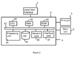
- control unit 4 As shown in Figure 2 , the control unit 4, as applied in the image processing system 1 comprises a Central Processing Unit (CPU) 40, a Random Access Memory (RAM) 48, a Read Only Memory (ROM) 60, a network card 46, an interface card 47, a hard disk (HD) 50 and a processing unit 54.
- CPU Central Processing Unit
- RAM Random Access Memory
- ROM Read Only Memory
- network card 46 an interface card 47
- HD hard disk
- processing unit 54 The aforementioned units are interconnected through a bus system 42.
- the control unit is connected to a network 8.
- the CPU 40 controls the respective units of the control unit 4, the local user interface 7, scanning unit 2 and the printing unit 3, in accordance with control programs stored on the ROM 60 or on the HD 50.
- the ROM 60 stores programs and data such as boot program, set-up program, various set-up data or the like, which are to be read out and executed by the CPU 40.
- the HD 50 is an example of a storage unit for storing and saving programs and data which make the CPU 40 execute a print process to be described later.
- the HD 50 also comprises an area for saving the data of externally submitted print jobs.
- the programs and data on the HD 50 are read out onto the RAM 48 by the CPU 40 as needed.
- the RAM 48 has an area for temporarily storing the programs and data read out from the ROM 60 and HD 50 by the CPU 40, and a work area which is used by the CPU 40 to execute various processes.
- Interface card 47 connects the control unit to scanning unit 2 and printing unit 3.
- Network card 46 connects the control unit 4 to the network 8 and is designed to provide communication with the workstations 9, and with other devices reachable via the network.
- the processing unit 54 may be implemented either as a software component of an operating system running on the control unit 52 or as a firmware program executed on the CPU 40.
- the processing unit 54 may include functions for reading, interpreting, processing and rasterizing the print job data.
- Said print job data may e.g. contain image data to be printed (i.e. fonts and graphics that describe the content of the document to be printed, described in a Page Description Language or the like), image processing attributes and print settings.
- the processing unit 54 further includes the various modules (i.e. the input module, the image enhancement module, the low pass filtering module and the conversion module) of the image processing system according to the invention which are used for processing a digital image.
- Basic modes of operation for the image processing apparatus 1 can include scanning, copying and printing. With the electric signals corresponding to the primary colours red (R), green (G) and blue (B) obtained during scanning, a digital image is assembled in the form of a raster image file.
- a raster image file is generally defined to be a rectangular array of regularly sampled values, known as pixels. Each pixel (picture element) has one or more numbers associated with it, generally specifying a colour which the pixel should be displayed in.
- the representation of an image may have each pixel specified by three 8 bit (24 bits total) colorimetric values (ranging from 0-255) defining the amount of R, G, and B respectively in each pixel.
- R, G, and B can be combined to form black, white, 254 shades of grey, and a vast array of colours (about 16 millions).
- the digital image obtained by the scanning unit 2 may be stored on a memory of the controller 6 and be handled according to a copy path, wherein the image is printed by the print engine 4.
- the digital image may be transferred from the controller to a client computer 9 (scan-to-file path).
- a user of the client computer 9 may decide to print a digital image, which reflects the printing mode of operation of the system.
- FIG. 3a schematically depicts an embodiment of an image processing system 300 according to the present invention, the image processing system 300 comprising modules 310, 320 and 330.
- the modules may be embodied as software components running under a certain operating system on a computer or they may be embodied in hardware as dedicated circuits like FPGAs or the like. Images going from one module to another are indicated as rectangles with a folded corner. In the following, an image is indicated by "I" and represents a set of image data.
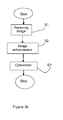
- Figure 3b schematically provides a flow diagram representing an embodiment of the image processing method according to the invention.
- Figures 3a and 3b are related in the sense that typically a particular component (as illustrated in Figure 3a ) is arranged to carry out a particular step of the method illustrated in Figure 3b .
- a digital image I D is received by the image processing system 300.
- the image will, in general, comprise luminance image data (providing information on the brightness of the image), represented by the luminance image I L , and chrominance image data (providing information on the colour of the image), represented by the chrominance image I C .
- luminance image data providing information on the brightness of the image
- chrominance image data providing information on the colour of the image
- the digital image I D needs to be converted to separate the luminance image data and the chrominance image data, thereby forming a luminance image I L and a chrominance image I C .
- processing of the digital image I D towards luminance image data and chrominance image data can be done in various colour spaces, such as Lab, LCH, IPT, YCbCr (also known as YCC), XYZ, etc, wherein Lab and LCH are expressions of the same colour space in Cartesian resp. polar co-ordinates.
- an image enhancement method is applied to the luminance image data only.
- image enhancement methods are edge enhancement, contrast enhancement and sharpness enhancement.
- Such methods provide an enhancement of the high spatial frequency content of the digital image I D .
- a "sharper" image can be obtained.
- Such enhancement of the high spatial frequency content of a scanned image can e.g. be obtained by appropriate filtering techniques of the digital image I D , as illustrated below.
- the image enhancement method is applied to the luminance image data only.
- the digital image I D can e.g. contain, on a pixel level certain inaccuracies, also referred to as artefacts.
- artefacts can e.g. be caused by registration errors in the scanning module or chromatic aberrations.
- artefacts may equally be caused by a difference in transfer function of the scanner between the scan-colours.
- the artefacts can e.g. be present in the digital images as coloured fringes.
- the image processing system is arranged to perform the image enhancement methods on the luminance information of the digital image only, thereby substantially avoiding the enhancement of the artefacts. It has been devised by the inventors that an image enhancement of a digital image may to a large extent also be obtained by performing the enhancement methods only on the luminance information of the raw image.
- an image enhancement method e.g. arranged to enhance the high spatial frequencies by filtering
- the high spatial frequency components in the chrominance image data are not enhanced.
- the occurrence of a visible colour cast may, to a large extent, be avoided.
- modified luminance image data represented by a modified luminance image I ML is obtained, as shown in Figure 3a .
- the modified luminance image I ML is converted, optionally together with the chrominance image I C (indicated by the dotted line 340) to an output digital image I OD .
- the modified luminance image I ML can directly be applied to generate a greyscale or black and white output digital image. Due to the selective application of the image enhancement method, the output digital image can result in the required contrast enhancement and sharpening without enhancing the artefacts present in the original digital image at pixel level.
- the image processing system is arranged to convert the output digital image to an output image in a colour space of an output unit such as a printer.
- the image processing system can be arranged to convert the output digital image to an image in a standard colour space such as sRGB or AdobeRGB. This output colour space may e.g. be different from the colour space of the digital image.
- filtering can be applied to the luminance image I L .
- filtering the scanned image data By filtering the scanned image data, one can, depending on the filter that is applied, e.g. sharpen an image or smoothen an image. In the former case, the high frequency spatial content of the image is lifted, in the latter case, the low frequency spatial content of the image is increased.
- Filtering an image thus offers the possibility of suppressing unwanted phenomena and / or enhancing the quality of desired phenomena, e.g. lines and text.
- Such filtering can be established by adjusting a pixel value (e.g. a luminance value) using the pixel values of pixels surrounding the pixel.
- two-dimensional linear filtering can be applied.
- N the order of the filter and h(k,l) is generally referred to as the impulse response of the filter.
- the filtering corresponds to a first order high-pass filter, meaning that high spatial frequencies are enhanced.
- the impulse response according to equation (3) equally provides an high pass filter. Both examples given illustrate image enhancement methods as can be applied in an embodiment of the present invention to enhance the high spatial frequency content of the digital image.
- equation (1) can be applied for low pass filtering as well.
- the filtering corresponds to a first order low-pass filter, meaning that high spatial frequencies are attenuated.
- the appropriate spatial frequencies need to be enhanced.
- the filtering involves adjusting pixel values based on neighbouring pixels, the actual resolution of the scanned image needs to be taken into account in order to obtain the required effect.
- FIG. 4a schematically depicts a further embodiment of an image processing system 400 according to the present invention, the image processing system 400 comprising modules 310, 320, 330 and 350.
- the modules may be embodied as software component running under a certain operating system on a computer or they may be embodied in hardware as dedicated circuits like FPGAs or the like.
- FIG. 4a substantially corresponds to the embodiment as shown in Figure 3a (indicated by the use of the same reference numbers for corresponding modules) apart from a low-pass filtering module 350 that enables the application of a low pass filtering to the chrominance image data, represented by the chrominance image I C of the digital image I D .
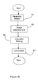
- Figure 4b schematically provides a flow diagram representing a further embodiment of an image processing method according to the invention.
- the method as illustrated in Figure 4b substantially corresponds to the method as described by Figure 3b (indicated by the use of the same reference signs) apart from step S4 indicating the low pass filtering that is applied.
- the chrominance image I C of the digital image I D as indicated in Figure 4a is converted by a low pass filtering module 350 (step S4 in Figure 4b indicating the low pass filtering being executed), to modified chrominance image data, represented by the modified chrominance image I MC in Figure 4a .
- the modified chrominance image I MC can be combined with the modified luminance image I ML (obtained by applying an image enhancement method to the luminance image I L of the digital image I D ) to generate an output digital image I OD . By doing so, the presence of artefacts can be mitigated. Artefacts present in the digital image (e.g.
- a low pass filtering e.g. a two-dimensional linear filtering as illustrated above
- performing a low pass filtering on the chrominance information can be done without noticeable affecting the sharpness of the output image.
- Applying low pass filtering of the chrominance information may also diminish the effect of coloured noise pixels already present in the input image.
- the image processing system according to the present invention can advantageously be applied in a scanner-printer apparatus.
- a scanner-printer apparatus may e.g. comprise a contact-type scanner or a reduction-type scanner for scanning an image and obtaining the digital image for processing by the image processing system.
- an image processing system and an image processing method are described.
- the image processing system is arranged to enhance the quality of a digital image by processing the image data.
- the image data comprises artefacts that could be enlarged by the processing
- the image enhancement process is only applied to the luminance image data of the digital image.
- the image processing system is arranged to convert the modified luminance image data and the chrominance image data of the digital image or the modified chrominance image data to an output digital image, preferably in a suitable colour space for processing by e.g. a printing unit.
- the image processing methods according to the invention can e.g. be implemented as a computer program arranged to perform the various steps of the methods on the original image date.
- the computer program can e.g. be made available through a data carrier (e.g. a disc such as a CD-ROM or a hard-disk or a memory unit such as a USB memory stick or a data carrier signal).
- a data carrier e.g. a disc such as a CD-ROM or a hard-disk or a memory unit such as a USB memory stick or a data carrier signal.
- image enhancement methods as described, in particular, the two-dimensional filtering methods are merely intended to illustrate the invention and not to limit the invention to particular methods of image enhancement.
Landscapes
- Engineering & Computer Science (AREA)
- Multimedia (AREA)
- Signal Processing (AREA)
- Color Image Communication Systems (AREA)
- Facsimile Image Signal Circuits (AREA)
- Image Processing (AREA)
Priority Applications (1)
| Application Number | Priority Date | Filing Date | Title |
|---|---|---|---|
| EP09152763A EP2219363A1 (de) | 2009-02-13 | 2009-02-13 | System und Verfahren zur Verarbeitung von digitalen Bildern |
Applications Claiming Priority (1)
| Application Number | Priority Date | Filing Date | Title |
|---|---|---|---|
| EP09152763A EP2219363A1 (de) | 2009-02-13 | 2009-02-13 | System und Verfahren zur Verarbeitung von digitalen Bildern |
Publications (1)
| Publication Number | Publication Date |
|---|---|
| EP2219363A1 true EP2219363A1 (de) | 2010-08-18 |
Family
ID=40810648
Family Applications (1)
| Application Number | Title | Priority Date | Filing Date |
|---|---|---|---|
| EP09152763A Ceased EP2219363A1 (de) | 2009-02-13 | 2009-02-13 | System und Verfahren zur Verarbeitung von digitalen Bildern |
Country Status (1)
| Country | Link |
|---|---|
| EP (1) | EP2219363A1 (de) |
Citations (5)
| Publication number | Priority date | Publication date | Assignee | Title |
|---|---|---|---|---|
| EP0377386A2 (de) * | 1989-01-05 | 1990-07-11 | Eastman Kodak Company | System zum interaktiven Abgleich des dynamischen Bereiches beim Drucken digitaler Bilder |
| US20030052979A1 (en) * | 2001-09-03 | 2003-03-20 | Kabushiki Kaisha Toyota Chuo Kenkyusho | Image processing method and apparatus |
| US6697107B1 (en) * | 1998-07-09 | 2004-02-24 | Eastman Kodak Company | Smoothing a digital color image using luminance values |
| US7085413B2 (en) | 2003-04-04 | 2006-08-01 | Good News Enterprises Limited | Image background detection and removal |
| WO2006094265A2 (en) * | 2005-03-03 | 2006-09-08 | Texas Instruments Incorporated | Sharpness filtering for picture-smoothing architectures |
-
2009
- 2009-02-13 EP EP09152763A patent/EP2219363A1/de not_active Ceased
Patent Citations (5)
| Publication number | Priority date | Publication date | Assignee | Title |
|---|---|---|---|---|
| EP0377386A2 (de) * | 1989-01-05 | 1990-07-11 | Eastman Kodak Company | System zum interaktiven Abgleich des dynamischen Bereiches beim Drucken digitaler Bilder |
| US6697107B1 (en) * | 1998-07-09 | 2004-02-24 | Eastman Kodak Company | Smoothing a digital color image using luminance values |
| US20030052979A1 (en) * | 2001-09-03 | 2003-03-20 | Kabushiki Kaisha Toyota Chuo Kenkyusho | Image processing method and apparatus |
| US7085413B2 (en) | 2003-04-04 | 2006-08-01 | Good News Enterprises Limited | Image background detection and removal |
| WO2006094265A2 (en) * | 2005-03-03 | 2006-09-08 | Texas Instruments Incorporated | Sharpness filtering for picture-smoothing architectures |
Non-Patent Citations (1)
| Title |
|---|
| AKIRA INOUE ET AL: "ADAPTIVE QUALITY IMPROVEMENT METHOD FOR COLOR IMAGES", NEC RESEARCH AND DEVELOPMENT, NIPPON ELECTRIC LTD. TOKYO, JP, vol. 35, no. 2, 1 April 1994 (1994-04-01), pages 180 - 186, XP000459703, ISSN: 0547-051X * |
Similar Documents
| Publication | Publication Date | Title |
|---|---|---|
| EP2396963B1 (de) | Bildverarbeitungssystem zur verarbeitung eines digitalen bilds und bildverarbeitungsverfahren zur verarbeitung eines digitalen bilds | |
| JP4890974B2 (ja) | 画像処理装置、及び画像処理方法 | |
| US5727137A (en) | Printer driver architecture for reducing band memory | |
| US7916352B2 (en) | Image processing apparatus, image processing method, program, and recording medium | |
| CN101848302A (zh) | 图像处理设备和控制方法 | |
| JP2009272774A (ja) | 画像処理装置、画像形成装置、画像処理方法、及びコンピュータプログラム | |
| EP1755329A1 (de) | Umwandlungsmethode, Apparat und Computer-Programm zur Umwandlung eines digitalen Bildes von einem Scanner | |
| US9124732B2 (en) | Image processing apparatus, image processing method, and program for the same | |
| JP2021106056A (ja) | 画像処理装置及び画像処理方法 | |
| US8743422B2 (en) | Image processing apparatus, image processing method, image processing program and printing device | |
| US10652431B2 (en) | Image forming apparatus performing specified-color removal process, control method therefor, and storage medium storing control program therefor | |
| JP6087334B2 (ja) | 画像処理装置及び画像形成装置 | |
| JP2008035511A (ja) | 画像処理装置および画像処理方法および画像処理プログラム | |
| JP2007088741A (ja) | 画像処理装置および画像処理方法 | |
| US20130176327A1 (en) | Method of rendering a colour image with spatial gamut mapping | |
| EP2219363A1 (de) | System und Verfahren zur Verarbeitung von digitalen Bildern | |
| JP6381289B2 (ja) | 画像形成装置、画像形成方法およびプログラム | |
| US8654403B2 (en) | Image processing apparatus and program therefor | |
| US11252298B2 (en) | Image processing apparatus, control method thereof, and storage medium | |
| JP6834701B2 (ja) | 画像処理装置、および、コンピュータプログラム | |
| JP5005734B2 (ja) | 画像処理装置、画像処理方法及び画像処理プログラム | |
| JP2011239090A (ja) | 画像処理装置、変換方法、及び、コンピュータプログラム | |
| JP2006270653A (ja) | 画像処理装置、画像処理方法及び画像処理プログラム | |
| JP2007036514A (ja) | 画像変換システム | |
| JP2010178011A (ja) | 画像処理システムおよび画像処理方法 |
Legal Events
| Date | Code | Title | Description |
|---|---|---|---|
| PUAI | Public reference made under article 153(3) epc to a published international application that has entered the european phase |
Free format text: ORIGINAL CODE: 0009012 |
|
| AK | Designated contracting states |
Kind code of ref document: A1 Designated state(s): AT BE BG CH CY CZ DE DK EE ES FI FR GB GR HR HU IE IS IT LI LT LU LV MC MK MT NL NO PL PT RO SE SI SK TR |
|
| AX | Request for extension of the european patent |
Extension state: AL BA RS |
|
| STAA | Information on the status of an ep patent application or granted ep patent |
Free format text: STATUS: THE APPLICATION HAS BEEN REFUSED |
|
| 18R | Application refused |
Effective date: 20100912 |