EP2218673B1 - Positionierung- und Stabilisierungvorrichtung für ein Fahrzeug - Google Patents
Positionierung- und Stabilisierungvorrichtung für ein Fahrzeug Download PDFInfo
- Publication number
- EP2218673B1 EP2218673B1 EP10290026.3A EP10290026A EP2218673B1 EP 2218673 B1 EP2218673 B1 EP 2218673B1 EP 10290026 A EP10290026 A EP 10290026A EP 2218673 B1 EP2218673 B1 EP 2218673B1
- Authority
- EP
- European Patent Office
- Prior art keywords
- arm
- vehicle
- jack
- wheels
- housed
- Prior art date
- Legal status (The legal status is an assumption and is not a legal conclusion. Google has not performed a legal analysis and makes no representation as to the accuracy of the status listed.)
- Not-in-force
Links
- 230000003019 stabilising effect Effects 0.000 title claims 3
- 230000006641 stabilisation Effects 0.000 description 11
- 238000011105 stabilization Methods 0.000 description 10
- 239000003381 stabilizer Substances 0.000 description 8
- 230000000087 stabilizing effect Effects 0.000 description 5
- 238000010586 diagram Methods 0.000 description 2
- 238000009434 installation Methods 0.000 description 2
- 230000010354 integration Effects 0.000 description 2
- 230000037237 body shape Effects 0.000 description 1
- 239000000725 suspension Substances 0.000 description 1
Images



Classifications
-
- B—PERFORMING OPERATIONS; TRANSPORTING
- B66—HOISTING; LIFTING; HAULING
- B66C—CRANES; LOAD-ENGAGING ELEMENTS OR DEVICES FOR CRANES, CAPSTANS, WINCHES, OR TACKLES
- B66C23/00—Cranes comprising essentially a beam, boom, or triangular structure acting as a cantilever and mounted for translatory of swinging movements in vertical or horizontal planes or a combination of such movements, e.g. jib-cranes, derricks, tower cranes
- B66C23/62—Constructional features or details
- B66C23/72—Counterweights or supports for balancing lifting couples
- B66C23/78—Supports, e.g. outriggers, for mobile cranes
- B66C23/80—Supports, e.g. outriggers, for mobile cranes hydraulically actuated
-
- F—MECHANICAL ENGINEERING; LIGHTING; HEATING; WEAPONS; BLASTING
- F41—WEAPONS
- F41A—FUNCTIONAL FEATURES OR DETAILS COMMON TO BOTH SMALLARMS AND ORDNANCE, e.g. CANNONS; MOUNTINGS FOR SMALLARMS OR ORDNANCE
- F41A23/00—Gun mountings, e.g. on vehicles; Disposition of guns on vehicles
- F41A23/56—Arrangements for adjusting the gun platform in the vertical or horizontal position
- F41A23/58—Hydraulic jacks
Definitions
- the technical field of the invention is that of positioning and stabilization devices for vehicles and in particular devices for stabilizing armored wheeled vehicles.
- the patent FR-2413505 describes such a device applied to a mechanical shovel.
- This patent shows lateral stabilizers formed of articulated arms which pass, by the action of a jack, a substantially vertical position along a side wall of the vehicle to a position in which the end of the arm is applied to floor.
- Such a configuration is relatively bulky and is not particularly applicable to a shielded vehicle whose external configuration is generally compact and must meet the constraints of size and stealth.
- the patent US 3572380 discloses a vehicle according to the preamble of claim 1 comprising a positioning frame for a concrete supply line.
- this document shows lateral stabilizers integral with a chassis, it is not strictly speaking a vehicle but rather a trailer and the problems of integration of the stabilizers vis-à-vis the side walls of a vehicle with wheels does not land.
- the object of the invention is to solve the problems posed by the known stabilizers.
- the invention proposes a compact positioning and stabilization device, easily integrable with a wheeled vehicle, and in particular with a shielded vehicle, a device making it possible to ensure effective stabilization with a reduced cylinder stroke and reduced forces for the cylinder.
- the subject of the invention is a wheeled vehicle, and in particular an armored vehicle, a vehicle comprising a body having lateral offsets inside which the wheels are housed, and comprising a positioning and stabilization device comprising at least a deployable lateral arm, which arm is articulated on a vehicle body between a folded position in which the arm is arranged along the body while a support end of the arm is disposed laterally away from the body and an extended position in which the support end of the arm is in contact on the ground, the passage from the folded position to the deployed position being ensured by means of a motor cylinder mounted between the body and the arm, the arm being housed in the folded position under one of the wheel offsets, the arm having a curved shape or well formed of several rectilinear sections forming angles between them, forming ui is such that when in the extended position, the support of the end on a horizontal plane ground on which is positioned the vehicle intervenes for an arm pivot angle less than or equal to 90 °.
- the arm may comprise at least two rectilinear sections forming an angle with each other, an outer section bearing the bearing end and an inner section being articulated relative to the body.
- the arm may be hingedly attached to a support itself secured to the body.
- a first end of the engine cylinder may be articulated on the support.
- the support may have a chute shape and in that arm or its inner portion will then be housed in this chute in the folded position of the arm.
- the width of the arm as well as the positioning of the point of attachment of the articulation of a second end of the engine cylinder on the arm will be chosen so that there is no interference between jack and wheels when turning wheels.
- the arm may comprise a hollow structure inside which the jack is housed, an opening being provided on this arm allowing the passage of the jack during its deployment movement.
- the arm may have a section with inclined walls.
- the positioning and stabilization device of the vehicle according to the invention will comprise at least two deployable lateral arms housed under each lateral offset of the body.
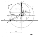
- the figure 1 schematizes a positioning and stabilizing arm of a device according to the prior art as for example described by FR-2413505 .
- This figure shows the arm in its two extreme positions: position folded in solid lines and deployed position in broken lines.
- the arm 1 is vertical in the folded position and inclined towards the ground 2 in the deployed position.
- the arm 1 has a bearing end 3 intended to be applied on the ground 2.
- the ground is represented here schematically as a horizontal plane positioned at the contact plane of the vehicle wheels with the ground (not shown wheels).
- the arm 1 is articulated on the body 4 at a hinge 5.
- the passage by a rotation in the direction of the arrow ⁇ , the folded position to the deployed position is provided by means of a jack motor 6 which is mounted between a first joint 7 secured to the body 4 and a second hinge 8 adjacent to the bearing end 3 of the arm 1. It has therefore positioned the joints 5 and 7 so that the output movement the rod of the cylinder 6 rotate the arm in the direction of the arrow ⁇ .
- the circle shown in phantom 9 represents the trajectory followed by the bearing end 3 of the arm 1. This circle 9 is centered on the articulation 5 and has the radius of the length of the arm 1.
- a circle in phantom 10 is the circle centered on the first articulation 7 of the cylinder 6 and having as radius the length L 1 of the jack 6 in the folded position.
- the angle ⁇ of pivoting of the arm is greater than 90 ° (for a starting position of the arm close to the vertical, which corresponds to the minimum lateral space requirement for the device).
- the lengthening of the jack 6 is then greater than 52%.
- the figure 2 shows schematically the kinematics of a positioning and stabilizing arm 1 of a device according to one embodiment of the invention.
- the floor 2, the body 4 and the joints 5 and 7 (which are fixed to the body) have been positioned at the same levels as on the floor. figure 1 .
- the arm 1 has a shape which is such that, when in the folded position, the arm 1 is stored along the body 4 while its support end 3 is arranged laterally to distance from said body 4.
- the arm 1 here comprises a section which is vertical while the support end 3 is in the rest position disposed laterally away from the vertical plane passing through the articulation 5 of the arm 1 on the body 4.
- the arm 1 is here formed of two rectilinear sections 1a and 1b which form an angle with each other (here a right angle).
- the outer portion 1b carries the bearing end 3 and it is the inner portion 1a which is fixed to the body by the hinge 5.
- the engine cylinder 6 is mounted between the first hinge 7 integral with the body 4 and a second hinge 8 which is arranged at a point attached near the junction zone 11 between the two sections (1a and 1b) of the arm.
- the circle 9 is centered on the articulation 5 and has for radius the length of the inner section 1a of the arm.
- the angle ⁇ for which the bearing end 3 is in contact with the ground is less than 90 °.
- lever arm 1b also makes it possible to reduce the support forces on the ground during stabilization, which is important in the case of soft ground. It should be noted that the wheelbase E 1 (prior art - figure 1 ) being lower than that E 2 ( figure 2 ) obtained with the invention, the effort to be exerted at ground level (bearing end 3) with the arm according to the invention is less to obtain the same resistant torque at the vehicle.
- an angle less than or equal to 30 ° may be chosen.
- Such an arrangement aims to arrange the body of the jack 6 as close as possible to the vertical when the device is in the folded position. This reduces the size of the device and facilitates the integration of the arms 1 in the vicinity of the wheels of the vehicle as will be described below.
- the invention is particularly well suited to the establishment of stabilizing arms at the wheel offset of an armored vehicle.
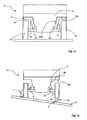
- Figures 3a, 3b , 4a and 4b show an armored vehicle 12 with wheels 13.
- This armored vehicle has a box 4 which has on each side of the vehicle a lateral offset 14 for housing the wheels 13.
- Each lateral offset 14 is here delimited by a horizontal plane 14a and an inclined plane 14b.
- the vehicle 12 carries four deployable side arms 1: two arms 1 which are housed under each lateral offset 14 of the body 4.
- Each arm comprises an inner section la which, in the folded position, is arranged parallel to the inclined plane 14b. It also comprises an outer section 1b which carries the bearing end 3 which has the shape of a plate mounted on the end of the section 1b by a pivot connection (axis of the pivot parallel to the axis of the vehicle).
- the angle between the two sections 1a, 1b is not here equal to 90 ° but is substantially equal to the angle formed between the planes 14a and 14b.
- the inner section 1a of the arm is hingedly attached to a support 15 which is itself rendered secured to the body for example by screws or welds.
- a support 15 which is itself rendered secured to the body for example by screws or welds.
- the deployable arms 1 are arranged laterally under each lateral offset 14 of the body. Such an arrangement allows, when setting in position, to use as long as possible the braking capacity of the vehicle. Indeed the arms 1 which are arranged in the direction of the slope (right arm on the figure 3b ) will bear on the ground 2 while the wheels 13 which are arranged on the other side of the vehicle still remain in contact with the ground 2.
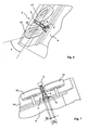
- FIGs 6 and 7 show more precisely an embodiment of an arm 1 in the folded position, which arm is disposed between the two front wheels 13 which are steered.
- the wheels are shown unreinforced on the figure 7 and pointed at their maximum angle ⁇ on the figure 6 .
- the arm 1 is fixed at its hinge 5 directly on the body 4 (here without intermediate support 15).
- the attachment point of the arm 1 on the body and the width of the arm 1 are chosen so that, when the cylinder 6 is in its folded position, there is no interference between the wheels 13 and the cylinder 6 as well as the arms 1.
- the arms 1 represented in Figures 6 and 7 have a width S1 at the level of the wheel turning zones 13 which is smaller than the width S2 of the arm at its attachment point 5 on the body 4.
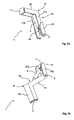
- FIGS 5a and 5b show more precisely the structure of an arm 1 according to another embodiment of the invention, which arm here is of constant width S and fixed to an intermediate support 15. This type of arm is fixed between two non-steerable wheels, by example the rear wheels.
- the inner section 1a and the outer section 1b are made in the form of cut sheets and mechanically welded.
- the inner portion 1a is in particular constituted by two walls 17a, 17b parallel to one another and separated by an opening 16 (see also Figures 4b and 6 ) which allows the passage of the cylinder 6 during the deployment movement of the arm 1.
- the arm 1 is made in the form of a hollow structure inside which is housed the cylinder 6 when the arm is folded, which makes the system very compact and protects the cylinder.
- the support 15 has a chute shape defined by two lateral flanges 15a, 15b.
- the inner portion 1a of the arm can be housed in this chute 15 in the folded position of the arm 1.
- the fixed articulation 7 of the jack 6 is also secured to the support 15, the other articulation (not visible on the Figures 5a, 5b ) being integral with the outer portion 1b.
- the cylinder 6 may be an electric cylinder or a hydraulic cylinder that will be connected to a power unit attached to the vehicle (such groups are generally present on military vehicles).
- figure 8 shows (in a frontal view similar to that of the figure 3a ) such an arm variant 1 which then has only one section 1 but which is curved so as to follow the profile of a cylindrical offset 14 of the body 4.
- the support end 3 will be arranged laterally away from the body 4 and the support of the end 3 on a horizontal plane floor will intervene for an arm pivot angle of less than or equal to 90 °.
- the arm 1 It is also possible to give the arm 1 a sectional profile that is not rectangular.
- Figures 9a and 9b show a mechano-welded arm 1 whose two sections 1a, 1b comprise parallel plates 17a, 17b which are connected to one another by inclined walls 18a and 18b.
- the section of arm 1 ( figure 9b ) therefore has a triangular part.
- Such a configuration makes it possible to ensure sufficient rigidity while reducing the bulk of the arm 1.
- the inclined walls 18a, 18b thus make it possible to have an arm which easily escapes the steering movements of the wheels of the vehicle, while the overall width S2 remains important.
- Such a configuration thus makes it possible to design an arm 1 positionable between the front wheels of the vehicle while maintaining a high rigidity.
Landscapes
- Engineering & Computer Science (AREA)
- Mechanical Engineering (AREA)
- General Engineering & Computer Science (AREA)
- Vehicle Body Suspensions (AREA)
- Body Structure For Vehicles (AREA)
Claims (9)
- Rad (13) gebundenes Fahrzeug (12), und insbesondere ein gepanzertes Fahrzeug (12), umfassend eine Karosserie (4), welche seitliche Versätze (14) aufweist, in deren Inneren sich die Räder (13) befinden, und umfassend eine Vorrichtung zur Positionierung und Stabilisierung, welche wenigstens einen entfaltbaren, seitlichen Arm (1) umfasst, wobei der Arm an einer Karosserie (4) des Fahrzeugs gelenkig zwischen einer zurück geklappten Position, in welcher sich der Arm (1) entlang der Karosserie (4) weggestaut befindet, während sich ein Abstützende (3) des Arms (1) von der Karosserie (4) seitlich beabstandet befindet, und einer entfalteten Position gelagert ist, in welcher das Abstützende (3) des Arms (1) mit dem Boden (2) in Kontakt ist, wobei der Übergang von der zurück geklappten Position in die entfaltete Position mit der Hilfe eines Antriebszylinders (6) gewährleistet wird, welcher zwischen der Karosserie (4) und dem Arm (1) montiert ist, wobei der Arm (1) eine gekrümmte Form aufweist oder auch aus mehreren geradlinigen Teilstücken (1a, 1b) gebildet wird, welche Winkel untereinander einschließen, wobei die Form dergestalt ist, dass, wenn er sich in entfalteter Position befindet, die Auflage des Endes (3) auf einem Boden mit horizontaler Ebene (2), auf welchem das Fahrzeug positioniert ist, bei einem Drehwinkel des Arms (1) von kleiner oder gleich 90° zustande kommt, wobei das Fahrzeug dadurch gekennzeichnet ist, dass sich der Arm (1) in zurück geklappter Position unter einem der Rad-Versätze (14) befindet.
- Fahrzeug nach Anspruch 1, dadurch gekennzeichnet, dass der Arm wenigstens zwei geradlinige Teilstücke (1a, 1b) umfasst, welche einen Winkel miteinander einschließen, wobei ein äußeres Teilstück (1b) das Abstützende (3) trägt und ein inneres Teilstück (la) in Bezug auf die Karosserie (4) angelenkt ist.
- Fahrzeug nach einem der Ansprüche 1 oder 2, dadurch gekennzeichnet, dass der Arm (1) in gelenkiger Weise an einem Träger (15) befestigt ist, welcher selbst fest mit der Karosserie (4) verbunden ist.
- Fahrzeug nach Anspruch 3, dadurch gekennzeichnet, dass ein erstes Ende des Antriebszylinders (6) am Träger (15) angelenkt ist.
- Rad (13) gebundenes Fahrzeug (12) insbesondere ein gepanzertes Fahrzeug nach Anspruch 4, dadurch gekennzeichnet, dass der Träger (15) die Form einer Ablaufrinne besitzt und dass der Arm (1) oder dessen inneres Teilstück (la) in zurück geklappter Position des Arms in dieser Ablaufrinne ruht.
- Rad (13) gebundenes Fahrzeug (12) insbesondere ein gepanzertes Fahrzeug nach einem der Ansprüche 1 bis 5, dadurch gekennzeichnet, dass die Breite des Arms (1) sowie die Positionierung des Anbringungspunktes der Anlenkung eines zweiten Endes des Antriebszylinders (6) an dem Arm derartig gewählt wird, dass es beim Einschlagen der Räder keine Wechselwirkung zwischen Zylinder (6) und Räder (13) gibt.
- Rad (13) gebundenes Fahrzeug (12) insbesondere ein gepanzertes Fahrzeug nach einem der Ansprüche 1 bis 6, dadurch gekennzeichnet, dass der Arm (1) eine hohle Struktur umfasst, in deren Inneren der Zylinder (6) ruht, wobei eine Öffnung (16) an diesem Arm (1) vorgesehen ist, welche den Durchgang des Zylinders (6) im Verlauf dessen Entfaltungsbewegung herstellt.
- Rad (13) gebundenes Fahrzeug (12) insbesondere ein gepanzertes Fahrzeug nach einem der Ansprüche 1 bis 7, dadurch gekennzeichnet, dass der Arm (1) einen Querschnitt aufweist, der geneigte Wände (18a, 18b) umfasst.
- Rad (13) gebundenes Fahrzeug (12) insbesondere ein gepanzertes Fahrzeug nach einem der Ansprüche 1 bis 8, dadurch gekennzeichnet, dass es wenigstens zwei entfaltbare, seitliche Arme (1) umfasst, welche sich unter jedem seitlichen Versatz (14) der Karosserie (4) befinden.
Priority Applications (1)
| Application Number | Priority Date | Filing Date | Title |
|---|---|---|---|
| PL10290026T PL2218673T3 (pl) | 2009-02-16 | 2010-01-20 | Urządzenie do pozycjonowania i stabilizacji dla pojazdu |
Applications Claiming Priority (1)
| Application Number | Priority Date | Filing Date | Title |
|---|---|---|---|
| FR0900699A FR2942189B1 (fr) | 2009-02-16 | 2009-02-16 | Dispositif de positionnement et stabilisations pour un vehicule |
Publications (2)
| Publication Number | Publication Date |
|---|---|
| EP2218673A1 EP2218673A1 (de) | 2010-08-18 |
| EP2218673B1 true EP2218673B1 (de) | 2014-03-12 |
Family
ID=41055107
Family Applications (1)
| Application Number | Title | Priority Date | Filing Date |
|---|---|---|---|
| EP10290026.3A Not-in-force EP2218673B1 (de) | 2009-02-16 | 2010-01-20 | Positionierung- und Stabilisierungvorrichtung für ein Fahrzeug |
Country Status (4)
| Country | Link |
|---|---|
| EP (1) | EP2218673B1 (de) |
| CA (1) | CA2692313A1 (de) |
| FR (1) | FR2942189B1 (de) |
| PL (1) | PL2218673T3 (de) |
Family Cites Families (4)
| Publication number | Priority date | Publication date | Assignee | Title |
|---|---|---|---|---|
| US3572380A (en) * | 1968-10-08 | 1971-03-23 | Challenge Cook Bros Inc | Concrete pump boom |
| NO123375B (de) * | 1970-04-03 | 1971-11-01 | Moelven Brug As | |
| US4132324A (en) | 1977-12-29 | 1979-01-02 | J. I. Case Company | Stabilizer assembly |
| DE20117775U1 (de) * | 2001-10-31 | 2003-03-20 | Liebherr-Hydraulikbagger GmbH, 88457 Kirchdorf | Räum- bzw. Planierschild für Baumaschinen |
-
2009
- 2009-02-16 FR FR0900699A patent/FR2942189B1/fr not_active Expired - Fee Related
-
2010
- 2010-01-20 EP EP10290026.3A patent/EP2218673B1/de not_active Not-in-force
- 2010-01-20 PL PL10290026T patent/PL2218673T3/pl unknown
- 2010-02-10 CA CA2692313A patent/CA2692313A1/fr not_active Abandoned
Also Published As
| Publication number | Publication date |
|---|---|
| FR2942189A1 (fr) | 2010-08-20 |
| CA2692313A1 (fr) | 2010-08-16 |
| EP2218673A1 (de) | 2010-08-18 |
| FR2942189B1 (fr) | 2015-04-17 |
| PL2218673T3 (pl) | 2014-07-31 |
Similar Documents
| Publication | Publication Date | Title |
|---|---|---|
| EP3347527B1 (de) | Schlitzwandfräse | |
| WO2017042499A2 (fr) | Machine de forage munie d'un dispositif d'ancrage permettant un deplacement horizontal du module de forage en position ancree | |
| WO2019162433A1 (fr) | Remorque inclinable comprenant des moyens d'actionnement mécanique et des moyens de verrouillage en position haute | |
| EP0945551B1 (de) | Kehrvorrichtung für Arbeitsfahrzeuge | |
| EP1965630B1 (de) | Landwirtschaftsvorrichtung mit einer verbesserten kupplungsstruktur | |
| EP3060455B1 (de) | Kraftfahrzeugvorderstruktur mit einem unter dem stossfänger angeordneten beweglichen spoiler | |
| EP4124478B1 (de) | Lenker oder dreieckslenker und verfahren zur herstellung eines solchen lenkers oder dreieckslenkers | |
| EP2218673B1 (de) | Positionierung- und Stabilisierungvorrichtung für ein Fahrzeug | |
| EP2326798B1 (de) | Transportvorrichtung mit variabler krümmung für einen tunnel | |
| EP0799730A1 (de) | Abschleppsystem für mindestens ein ziehendes Fahrzeug und gezogenes Fahrzeug undKraftfahrzeug geeignet zum Gebrauch in einem solchem System | |
| EP2011698B1 (de) | Einziehbarer Unterfahrschutz | |
| EP1893424B1 (de) | Boomerang-artiger trägerarm mit ansteigender erweiterung einer kante und entsprechendes fahrzeug | |
| EP0493284B1 (de) | Schwenkbetätiger zum Ausführen aller geradlinigen oder rotierenden Bewegungen | |
| EP2485977B1 (de) | Hebegerät für einen mäher mit extern montiertem heber | |
| FR2772228A1 (fr) | Ramasseur repliable pour ensileuse | |
| FR2927285A1 (fr) | Dispositif de manutention pour le chargement et le dechargement d'un conteneur. | |
| FR2882622A1 (fr) | Andaineuse a bras porte-rotors telescopiques | |
| FR2660337A1 (fr) | Dispositif de derasement d'accotement combine a un godet de curage de fosses. | |
| WO2024165417A1 (fr) | Système de levage et de stabilisation d'un vehicule | |
| WO2022023378A1 (fr) | Train de roulage pour véhicule amphibie | |
| FR2728861A1 (fr) | Vehicule automobile comportant une structure mobile de support de roue de secours et structure mobile de support de roue de secours | |
| FR2912094A1 (fr) | Compas de bennage | |
| FR2883698A1 (fr) | Dispositif d'attelage permettant d'atteler un outil a un vehicule | |
| EP1775157A1 (de) | Fördereinheit für ein Kipperfahrzeug | |
| FR3070668A1 (fr) | Diffuseur arriere mobile a engrenage |
Legal Events
| Date | Code | Title | Description |
|---|---|---|---|
| PUAI | Public reference made under article 153(3) epc to a published international application that has entered the european phase |
Free format text: ORIGINAL CODE: 0009012 |
|
| AK | Designated contracting states |
Kind code of ref document: A1 Designated state(s): AT BE BG CH CY CZ DE DK EE ES FI FR GB GR HR HU IE IS IT LI LT LU LV MC MK MT NL NO PL PT RO SE SI SK SM TR |
|
| AX | Request for extension of the european patent |
Extension state: AL BA RS |
|
| 17P | Request for examination filed |
Effective date: 20110218 |
|
| RIC1 | Information provided on ipc code assigned before grant |
Ipc: F41A 23/58 20060101ALI20130723BHEP Ipc: B66C 23/80 20060101AFI20130723BHEP |
|
| GRAP | Despatch of communication of intention to grant a patent |
Free format text: ORIGINAL CODE: EPIDOSNIGR1 |
|
| INTG | Intention to grant announced |
Effective date: 20131001 |
|
| GRAS | Grant fee paid |
Free format text: ORIGINAL CODE: EPIDOSNIGR3 |
|
| GRAA | (expected) grant |
Free format text: ORIGINAL CODE: 0009210 |
|
| AK | Designated contracting states |
Kind code of ref document: B1 Designated state(s): AT BE BG CH CY CZ DE DK EE ES FI FR GB GR HR HU IE IS IT LI LT LU LV MC MK MT NL NO PL PT RO SE SI SK SM TR |
|
| REG | Reference to a national code |
Ref country code: GB Ref legal event code: FG4D Free format text: NOT ENGLISH |
|
| REG | Reference to a national code |
Ref country code: CH Ref legal event code: EP |
|
| REG | Reference to a national code |
Ref country code: AT Ref legal event code: REF Ref document number: 656156 Country of ref document: AT Kind code of ref document: T Effective date: 20140315 |
|
| REG | Reference to a national code |
Ref country code: IE Ref legal event code: FG4D Free format text: LANGUAGE OF EP DOCUMENT: FRENCH |
|
| REG | Reference to a national code |
Ref country code: DE Ref legal event code: R096 Ref document number: 602010014163 Country of ref document: DE Effective date: 20140424 |
|
| REG | Reference to a national code |
Ref country code: SE Ref legal event code: TRGR |
|
| REG | Reference to a national code |
Ref country code: NL Ref legal event code: VDEP Effective date: 20140312 |
|
| PG25 | Lapsed in a contracting state [announced via postgrant information from national office to epo] |
Ref country code: NO Free format text: LAPSE BECAUSE OF FAILURE TO SUBMIT A TRANSLATION OF THE DESCRIPTION OR TO PAY THE FEE WITHIN THE PRESCRIBED TIME-LIMIT Effective date: 20140612 Ref country code: LT Free format text: LAPSE BECAUSE OF FAILURE TO SUBMIT A TRANSLATION OF THE DESCRIPTION OR TO PAY THE FEE WITHIN THE PRESCRIBED TIME-LIMIT Effective date: 20140312 |
|
| REG | Reference to a national code |
Ref country code: PL Ref legal event code: T3 |
|
| REG | Reference to a national code |
Ref country code: LT Ref legal event code: MG4D |
|
| PG25 | Lapsed in a contracting state [announced via postgrant information from national office to epo] |
Ref country code: CY Free format text: LAPSE BECAUSE OF FAILURE TO SUBMIT A TRANSLATION OF THE DESCRIPTION OR TO PAY THE FEE WITHIN THE PRESCRIBED TIME-LIMIT Effective date: 20140312 |
|
| PG25 | Lapsed in a contracting state [announced via postgrant information from national office to epo] |
Ref country code: HR Free format text: LAPSE BECAUSE OF FAILURE TO SUBMIT A TRANSLATION OF THE DESCRIPTION OR TO PAY THE FEE WITHIN THE PRESCRIBED TIME-LIMIT Effective date: 20140312 Ref country code: LV Free format text: LAPSE BECAUSE OF FAILURE TO SUBMIT A TRANSLATION OF THE DESCRIPTION OR TO PAY THE FEE WITHIN THE PRESCRIBED TIME-LIMIT Effective date: 20140312 |
|
| PG25 | Lapsed in a contracting state [announced via postgrant information from national office to epo] |
Ref country code: EE Free format text: LAPSE BECAUSE OF FAILURE TO SUBMIT A TRANSLATION OF THE DESCRIPTION OR TO PAY THE FEE WITHIN THE PRESCRIBED TIME-LIMIT Effective date: 20140312 Ref country code: RO Free format text: LAPSE BECAUSE OF FAILURE TO SUBMIT A TRANSLATION OF THE DESCRIPTION OR TO PAY THE FEE WITHIN THE PRESCRIBED TIME-LIMIT Effective date: 20140312 Ref country code: NL Free format text: LAPSE BECAUSE OF FAILURE TO SUBMIT A TRANSLATION OF THE DESCRIPTION OR TO PAY THE FEE WITHIN THE PRESCRIBED TIME-LIMIT Effective date: 20140312 Ref country code: IS Free format text: LAPSE BECAUSE OF FAILURE TO SUBMIT A TRANSLATION OF THE DESCRIPTION OR TO PAY THE FEE WITHIN THE PRESCRIBED TIME-LIMIT Effective date: 20140712 Ref country code: CZ Free format text: LAPSE BECAUSE OF FAILURE TO SUBMIT A TRANSLATION OF THE DESCRIPTION OR TO PAY THE FEE WITHIN THE PRESCRIBED TIME-LIMIT Effective date: 20140312 Ref country code: BG Free format text: LAPSE BECAUSE OF FAILURE TO SUBMIT A TRANSLATION OF THE DESCRIPTION OR TO PAY THE FEE WITHIN THE PRESCRIBED TIME-LIMIT Effective date: 20140612 |
|
| PG25 | Lapsed in a contracting state [announced via postgrant information from national office to epo] |
Ref country code: ES Free format text: LAPSE BECAUSE OF FAILURE TO SUBMIT A TRANSLATION OF THE DESCRIPTION OR TO PAY THE FEE WITHIN THE PRESCRIBED TIME-LIMIT Effective date: 20140312 Ref country code: SK Free format text: LAPSE BECAUSE OF FAILURE TO SUBMIT A TRANSLATION OF THE DESCRIPTION OR TO PAY THE FEE WITHIN THE PRESCRIBED TIME-LIMIT Effective date: 20140312 |
|
| REG | Reference to a national code |
Ref country code: DE Ref legal event code: R097 Ref document number: 602010014163 Country of ref document: DE |
|
| PG25 | Lapsed in a contracting state [announced via postgrant information from national office to epo] |
Ref country code: PT Free format text: LAPSE BECAUSE OF FAILURE TO SUBMIT A TRANSLATION OF THE DESCRIPTION OR TO PAY THE FEE WITHIN THE PRESCRIBED TIME-LIMIT Effective date: 20140714 |
|
| PLBE | No opposition filed within time limit |
Free format text: ORIGINAL CODE: 0009261 |
|
| STAA | Information on the status of an ep patent application or granted ep patent |
Free format text: STATUS: NO OPPOSITION FILED WITHIN TIME LIMIT |
|
| PG25 | Lapsed in a contracting state [announced via postgrant information from national office to epo] |
Ref country code: DK Free format text: LAPSE BECAUSE OF FAILURE TO SUBMIT A TRANSLATION OF THE DESCRIPTION OR TO PAY THE FEE WITHIN THE PRESCRIBED TIME-LIMIT Effective date: 20140312 |
|
| 26N | No opposition filed |
Effective date: 20141215 |
|
| REG | Reference to a national code |
Ref country code: DE Ref legal event code: R097 Ref document number: 602010014163 Country of ref document: DE Effective date: 20141215 |
|
| PG25 | Lapsed in a contracting state [announced via postgrant information from national office to epo] |
Ref country code: BE Free format text: LAPSE BECAUSE OF NON-PAYMENT OF DUE FEES Effective date: 20150131 |
|
| PG25 | Lapsed in a contracting state [announced via postgrant information from national office to epo] |
Ref country code: SI Free format text: LAPSE BECAUSE OF FAILURE TO SUBMIT A TRANSLATION OF THE DESCRIPTION OR TO PAY THE FEE WITHIN THE PRESCRIBED TIME-LIMIT Effective date: 20140312 |
|
| PG25 | Lapsed in a contracting state [announced via postgrant information from national office to epo] |
Ref country code: LU Free format text: LAPSE BECAUSE OF FAILURE TO SUBMIT A TRANSLATION OF THE DESCRIPTION OR TO PAY THE FEE WITHIN THE PRESCRIBED TIME-LIMIT Effective date: 20150120 |
|
| GBPC | Gb: european patent ceased through non-payment of renewal fee |
Effective date: 20150120 |
|
| PG25 | Lapsed in a contracting state [announced via postgrant information from national office to epo] |
Ref country code: MC Free format text: LAPSE BECAUSE OF FAILURE TO SUBMIT A TRANSLATION OF THE DESCRIPTION OR TO PAY THE FEE WITHIN THE PRESCRIBED TIME-LIMIT Effective date: 20140312 |
|
| PG25 | Lapsed in a contracting state [announced via postgrant information from national office to epo] |
Ref country code: GB Free format text: LAPSE BECAUSE OF NON-PAYMENT OF DUE FEES Effective date: 20150120 |
|
| REG | Reference to a national code |
Ref country code: IE Ref legal event code: MM4A |
|
| REG | Reference to a national code |
Ref country code: FR Ref legal event code: PLFP Year of fee payment: 7 |
|
| PG25 | Lapsed in a contracting state [announced via postgrant information from national office to epo] |
Ref country code: IE Free format text: LAPSE BECAUSE OF NON-PAYMENT OF DUE FEES Effective date: 20150120 |
|
| PG25 | Lapsed in a contracting state [announced via postgrant information from national office to epo] |
Ref country code: GR Free format text: LAPSE BECAUSE OF FAILURE TO SUBMIT A TRANSLATION OF THE DESCRIPTION OR TO PAY THE FEE WITHIN THE PRESCRIBED TIME-LIMIT Effective date: 20140613 |
|
| REG | Reference to a national code |
Ref country code: FR Ref legal event code: PLFP Year of fee payment: 8 |
|
| PG25 | Lapsed in a contracting state [announced via postgrant information from national office to epo] |
Ref country code: MT Free format text: LAPSE BECAUSE OF FAILURE TO SUBMIT A TRANSLATION OF THE DESCRIPTION OR TO PAY THE FEE WITHIN THE PRESCRIBED TIME-LIMIT Effective date: 20140312 |
|
| PGFP | Annual fee paid to national office [announced via postgrant information from national office to epo] |
Ref country code: SE Payment date: 20161221 Year of fee payment: 8 |
|
| PG25 | Lapsed in a contracting state [announced via postgrant information from national office to epo] |
Ref country code: SM Free format text: LAPSE BECAUSE OF FAILURE TO SUBMIT A TRANSLATION OF THE DESCRIPTION OR TO PAY THE FEE WITHIN THE PRESCRIBED TIME-LIMIT Effective date: 20140312 Ref country code: HU Free format text: LAPSE BECAUSE OF FAILURE TO SUBMIT A TRANSLATION OF THE DESCRIPTION OR TO PAY THE FEE WITHIN THE PRESCRIBED TIME-LIMIT; INVALID AB INITIO Effective date: 20100120 |
|
| PGFP | Annual fee paid to national office [announced via postgrant information from national office to epo] |
Ref country code: AT Payment date: 20161220 Year of fee payment: 8 |
|
| PGFP | Annual fee paid to national office [announced via postgrant information from national office to epo] |
Ref country code: IT Payment date: 20170103 Year of fee payment: 8 |
|
| REG | Reference to a national code |
Ref country code: FR Ref legal event code: PLFP Year of fee payment: 9 |
|
| PG25 | Lapsed in a contracting state [announced via postgrant information from national office to epo] |
Ref country code: MK Free format text: LAPSE BECAUSE OF FAILURE TO SUBMIT A TRANSLATION OF THE DESCRIPTION OR TO PAY THE FEE WITHIN THE PRESCRIBED TIME-LIMIT Effective date: 20140312 |
|
| REG | Reference to a national code |
Ref country code: SE Ref legal event code: EUG |
|
| REG | Reference to a national code |
Ref country code: AT Ref legal event code: MM01 Ref document number: 656156 Country of ref document: AT Kind code of ref document: T Effective date: 20180120 |
|
| PG25 | Lapsed in a contracting state [announced via postgrant information from national office to epo] |
Ref country code: SE Free format text: LAPSE BECAUSE OF NON-PAYMENT OF DUE FEES Effective date: 20180121 |
|
| PG25 | Lapsed in a contracting state [announced via postgrant information from national office to epo] |
Ref country code: AT Free format text: LAPSE BECAUSE OF NON-PAYMENT OF DUE FEES Effective date: 20180120 |
|
| PGFP | Annual fee paid to national office [announced via postgrant information from national office to epo] |
Ref country code: FI Payment date: 20181219 Year of fee payment: 10 Ref country code: PL Payment date: 20181219 Year of fee payment: 10 |
|
| PG25 | Lapsed in a contracting state [announced via postgrant information from national office to epo] |
Ref country code: IT Free format text: LAPSE BECAUSE OF NON-PAYMENT OF DUE FEES Effective date: 20180120 |
|
| PGFP | Annual fee paid to national office [announced via postgrant information from national office to epo] |
Ref country code: FR Payment date: 20181220 Year of fee payment: 10 Ref country code: CH Payment date: 20181221 Year of fee payment: 10 |
|
| PGFP | Annual fee paid to national office [announced via postgrant information from national office to epo] |
Ref country code: DE Payment date: 20181218 Year of fee payment: 10 |
|
| PGFP | Annual fee paid to national office [announced via postgrant information from national office to epo] |
Ref country code: TR Payment date: 20190108 Year of fee payment: 10 |
|
| REG | Reference to a national code |
Ref country code: DE Ref legal event code: R119 Ref document number: 602010014163 Country of ref document: DE |
|
| REG | Reference to a national code |
Ref country code: FI Ref legal event code: MAE |
|
| REG | Reference to a national code |
Ref country code: CH Ref legal event code: PL |
|
| PG25 | Lapsed in a contracting state [announced via postgrant information from national office to epo] |
Ref country code: DE Free format text: LAPSE BECAUSE OF NON-PAYMENT OF DUE FEES Effective date: 20200801 Ref country code: FR Free format text: LAPSE BECAUSE OF NON-PAYMENT OF DUE FEES Effective date: 20200131 Ref country code: FI Free format text: LAPSE BECAUSE OF NON-PAYMENT OF DUE FEES Effective date: 20200120 |
|
| PG25 | Lapsed in a contracting state [announced via postgrant information from national office to epo] |
Ref country code: CH Free format text: LAPSE BECAUSE OF NON-PAYMENT OF DUE FEES Effective date: 20200131 Ref country code: LI Free format text: LAPSE BECAUSE OF NON-PAYMENT OF DUE FEES Effective date: 20200131 |
|
| PG25 | Lapsed in a contracting state [announced via postgrant information from national office to epo] |
Ref country code: PL Free format text: LAPSE BECAUSE OF NON-PAYMENT OF DUE FEES Effective date: 20200120 |
|
| PG25 | Lapsed in a contracting state [announced via postgrant information from national office to epo] |
Ref country code: TR Free format text: LAPSE BECAUSE OF NON-PAYMENT OF DUE FEES Effective date: 20200120 |