EP2218568A1 - Schnecken-Maschine - Google Patents
Schnecken-Maschine Download PDFInfo
- Publication number
- EP2218568A1 EP2218568A1 EP09001867A EP09001867A EP2218568A1 EP 2218568 A1 EP2218568 A1 EP 2218568A1 EP 09001867 A EP09001867 A EP 09001867A EP 09001867 A EP09001867 A EP 09001867A EP 2218568 A1 EP2218568 A1 EP 2218568A1
- Authority
- EP
- European Patent Office
- Prior art keywords
- screw machine
- machine according
- housing
- base body
- metal
- Prior art date
- Legal status (The legal status is an assumption and is not a legal conclusion. Google has not performed a legal analysis and makes no representation as to the accuracy of the status listed.)
- Granted
Links
Images




Classifications
-
- B—PERFORMING OPERATIONS; TRANSPORTING
- B01—PHYSICAL OR CHEMICAL PROCESSES OR APPARATUS IN GENERAL
- B01D—SEPARATION
- B01D39/00—Filtering material for liquid or gaseous fluids
- B01D39/14—Other self-supporting filtering material ; Other filtering material
- B01D39/20—Other self-supporting filtering material ; Other filtering material of inorganic material, e.g. asbestos paper, metallic filtering material of non-woven wires
- B01D39/2027—Metallic material
- B01D39/2041—Metallic material the material being filamentary or fibrous
-
- B—PERFORMING OPERATIONS; TRANSPORTING
- B29—WORKING OF PLASTICS; WORKING OF SUBSTANCES IN A PLASTIC STATE IN GENERAL
- B29B—PREPARATION OR PRETREATMENT OF THE MATERIAL TO BE SHAPED; MAKING GRANULES OR PREFORMS; RECOVERY OF PLASTICS OR OTHER CONSTITUENTS OF WASTE MATERIAL CONTAINING PLASTICS
- B29B7/00—Mixing; Kneading
- B29B7/30—Mixing; Kneading continuous, with mechanical mixing or kneading devices
- B29B7/34—Mixing; Kneading continuous, with mechanical mixing or kneading devices with movable mixing or kneading devices
- B29B7/38—Mixing; Kneading continuous, with mechanical mixing or kneading devices with movable mixing or kneading devices rotary
- B29B7/46—Mixing; Kneading continuous, with mechanical mixing or kneading devices with movable mixing or kneading devices rotary with more than one shaft
- B29B7/48—Mixing; Kneading continuous, with mechanical mixing or kneading devices with movable mixing or kneading devices rotary with more than one shaft with intermeshing devices, e.g. screws
- B29B7/482—Mixing; Kneading continuous, with mechanical mixing or kneading devices with movable mixing or kneading devices rotary with more than one shaft with intermeshing devices, e.g. screws provided with screw parts in addition to other mixing parts, e.g. paddles, gears, discs
- B29B7/483—Mixing; Kneading continuous, with mechanical mixing or kneading devices with movable mixing or kneading devices rotary with more than one shaft with intermeshing devices, e.g. screws provided with screw parts in addition to other mixing parts, e.g. paddles, gears, discs the other mixing parts being discs perpendicular to the screw axis
-
- B—PERFORMING OPERATIONS; TRANSPORTING
- B29—WORKING OF PLASTICS; WORKING OF SUBSTANCES IN A PLASTIC STATE IN GENERAL
- B29B—PREPARATION OR PRETREATMENT OF THE MATERIAL TO BE SHAPED; MAKING GRANULES OR PREFORMS; RECOVERY OF PLASTICS OR OTHER CONSTITUENTS OF WASTE MATERIAL CONTAINING PLASTICS
- B29B7/00—Mixing; Kneading
- B29B7/30—Mixing; Kneading continuous, with mechanical mixing or kneading devices
- B29B7/34—Mixing; Kneading continuous, with mechanical mixing or kneading devices with movable mixing or kneading devices
- B29B7/38—Mixing; Kneading continuous, with mechanical mixing or kneading devices with movable mixing or kneading devices rotary
- B29B7/46—Mixing; Kneading continuous, with mechanical mixing or kneading devices with movable mixing or kneading devices rotary with more than one shaft
- B29B7/48—Mixing; Kneading continuous, with mechanical mixing or kneading devices with movable mixing or kneading devices rotary with more than one shaft with intermeshing devices, e.g. screws
- B29B7/488—Parts, e.g. casings, sealings; Accessories, e.g. flow controlling or throttling devices
-
- B—PERFORMING OPERATIONS; TRANSPORTING
- B29—WORKING OF PLASTICS; WORKING OF SUBSTANCES IN A PLASTIC STATE IN GENERAL
- B29B—PREPARATION OR PRETREATMENT OF THE MATERIAL TO BE SHAPED; MAKING GRANULES OR PREFORMS; RECOVERY OF PLASTICS OR OTHER CONSTITUENTS OF WASTE MATERIAL CONTAINING PLASTICS
- B29B7/00—Mixing; Kneading
- B29B7/80—Component parts, details or accessories; Auxiliary operations
- B29B7/84—Venting or degassing ; Removing liquids, e.g. by evaporating components
- B29B7/845—Venting, degassing or removing evaporated components in devices with rotary stirrers
-
- B—PERFORMING OPERATIONS; TRANSPORTING
- B29—WORKING OF PLASTICS; WORKING OF SUBSTANCES IN A PLASTIC STATE IN GENERAL
- B29B—PREPARATION OR PRETREATMENT OF THE MATERIAL TO BE SHAPED; MAKING GRANULES OR PREFORMS; RECOVERY OF PLASTICS OR OTHER CONSTITUENTS OF WASTE MATERIAL CONTAINING PLASTICS
- B29B7/00—Mixing; Kneading
- B29B7/80—Component parts, details or accessories; Auxiliary operations
- B29B7/86—Component parts, details or accessories; Auxiliary operations for working at sub- or superatmospheric pressure
-
- B—PERFORMING OPERATIONS; TRANSPORTING
- B29—WORKING OF PLASTICS; WORKING OF SUBSTANCES IN A PLASTIC STATE IN GENERAL
- B29C—SHAPING OR JOINING OF PLASTICS; SHAPING OF MATERIAL IN A PLASTIC STATE, NOT OTHERWISE PROVIDED FOR; AFTER-TREATMENT OF THE SHAPED PRODUCTS, e.g. REPAIRING
- B29C48/00—Extrusion moulding, i.e. expressing the moulding material through a die or nozzle which imparts the desired form; Apparatus therefor
- B29C48/25—Component parts, details or accessories; Auxiliary operations
- B29C48/36—Means for plasticising or homogenising the moulding material or forcing it through the nozzle or die
- B29C48/375—Plasticisers, homogenisers or feeders comprising two or more stages
- B29C48/39—Plasticisers, homogenisers or feeders comprising two or more stages a first extruder feeding the melt into an intermediate location of a second extruder
-
- B—PERFORMING OPERATIONS; TRANSPORTING
- B29—WORKING OF PLASTICS; WORKING OF SUBSTANCES IN A PLASTIC STATE IN GENERAL
- B29C—SHAPING OR JOINING OF PLASTICS; SHAPING OF MATERIAL IN A PLASTIC STATE, NOT OTHERWISE PROVIDED FOR; AFTER-TREATMENT OF THE SHAPED PRODUCTS, e.g. REPAIRING
- B29C48/00—Extrusion moulding, i.e. expressing the moulding material through a die or nozzle which imparts the desired form; Apparatus therefor
- B29C48/25—Component parts, details or accessories; Auxiliary operations
- B29C48/36—Means for plasticising or homogenising the moulding material or forcing it through the nozzle or die
- B29C48/395—Means for plasticising or homogenising the moulding material or forcing it through the nozzle or die using screws surrounded by a cooperating barrel, e.g. single screw extruders
- B29C48/40—Means for plasticising or homogenising the moulding material or forcing it through the nozzle or die using screws surrounded by a cooperating barrel, e.g. single screw extruders using two or more parallel screws or at least two parallel non-intermeshing screws, e.g. twin screw extruders
-
- B—PERFORMING OPERATIONS; TRANSPORTING
- B29—WORKING OF PLASTICS; WORKING OF SUBSTANCES IN A PLASTIC STATE IN GENERAL
- B29C—SHAPING OR JOINING OF PLASTICS; SHAPING OF MATERIAL IN A PLASTIC STATE, NOT OTHERWISE PROVIDED FOR; AFTER-TREATMENT OF THE SHAPED PRODUCTS, e.g. REPAIRING
- B29C48/00—Extrusion moulding, i.e. expressing the moulding material through a die or nozzle which imparts the desired form; Apparatus therefor
- B29C48/25—Component parts, details or accessories; Auxiliary operations
- B29C48/36—Means for plasticising or homogenising the moulding material or forcing it through the nozzle or die
- B29C48/50—Details of extruders
- B29C48/505—Screws
- B29C48/57—Screws provided with kneading disc-like elements, e.g. with oval-shaped elements
-
- B—PERFORMING OPERATIONS; TRANSPORTING
- B29—WORKING OF PLASTICS; WORKING OF SUBSTANCES IN A PLASTIC STATE IN GENERAL
- B29C—SHAPING OR JOINING OF PLASTICS; SHAPING OF MATERIAL IN A PLASTIC STATE, NOT OTHERWISE PROVIDED FOR; AFTER-TREATMENT OF THE SHAPED PRODUCTS, e.g. REPAIRING
- B29C48/00—Extrusion moulding, i.e. expressing the moulding material through a die or nozzle which imparts the desired form; Apparatus therefor
- B29C48/25—Component parts, details or accessories; Auxiliary operations
- B29C48/36—Means for plasticising or homogenising the moulding material or forcing it through the nozzle or die
- B29C48/50—Details of extruders
- B29C48/76—Venting, drying means; Degassing means
- B29C48/763—Vent constructions, e.g. venting means avoiding melt escape
-
- B—PERFORMING OPERATIONS; TRANSPORTING
- B29—WORKING OF PLASTICS; WORKING OF SUBSTANCES IN A PLASTIC STATE IN GENERAL
- B29C—SHAPING OR JOINING OF PLASTICS; SHAPING OF MATERIAL IN A PLASTIC STATE, NOT OTHERWISE PROVIDED FOR; AFTER-TREATMENT OF THE SHAPED PRODUCTS, e.g. REPAIRING
- B29C48/00—Extrusion moulding, i.e. expressing the moulding material through a die or nozzle which imparts the desired form; Apparatus therefor
- B29C48/25—Component parts, details or accessories; Auxiliary operations
- B29C48/36—Means for plasticising or homogenising the moulding material or forcing it through the nozzle or die
- B29C48/50—Details of extruders
- B29C48/76—Venting, drying means; Degassing means
- B29C48/765—Venting, drying means; Degassing means in the extruder apparatus
- B29C48/766—Venting, drying means; Degassing means in the extruder apparatus in screw extruders
- B29C48/767—Venting, drying means; Degassing means in the extruder apparatus in screw extruders through a degassing opening of a barrel
-
- B—PERFORMING OPERATIONS; TRANSPORTING
- B29—WORKING OF PLASTICS; WORKING OF SUBSTANCES IN A PLASTIC STATE IN GENERAL
- B29C—SHAPING OR JOINING OF PLASTICS; SHAPING OF MATERIAL IN A PLASTIC STATE, NOT OTHERWISE PROVIDED FOR; AFTER-TREATMENT OF THE SHAPED PRODUCTS, e.g. REPAIRING
- B29C48/00—Extrusion moulding, i.e. expressing the moulding material through a die or nozzle which imparts the desired form; Apparatus therefor
- B29C48/25—Component parts, details or accessories; Auxiliary operations
- B29C48/78—Thermal treatment of the extrusion moulding material or of preformed parts or layers, e.g. by heating or cooling
- B29C48/793—Thermal treatment of the extrusion moulding material or of preformed parts or layers, e.g. by heating or cooling upstream of the plasticising zone, e.g. heating in the hopper
- B29C48/797—Cooling
-
- B—PERFORMING OPERATIONS; TRANSPORTING
- B29—WORKING OF PLASTICS; WORKING OF SUBSTANCES IN A PLASTIC STATE IN GENERAL
- B29C—SHAPING OR JOINING OF PLASTICS; SHAPING OF MATERIAL IN A PLASTIC STATE, NOT OTHERWISE PROVIDED FOR; AFTER-TREATMENT OF THE SHAPED PRODUCTS, e.g. REPAIRING
- B29C48/00—Extrusion moulding, i.e. expressing the moulding material through a die or nozzle which imparts the desired form; Apparatus therefor
- B29C48/25—Component parts, details or accessories; Auxiliary operations
- B29C48/78—Thermal treatment of the extrusion moulding material or of preformed parts or layers, e.g. by heating or cooling
- B29C48/80—Thermal treatment of the extrusion moulding material or of preformed parts or layers, e.g. by heating or cooling at the plasticising zone, e.g. by heating cylinders
- B29C48/83—Heating or cooling the cylinders
- B29C48/834—Cooling
-
- B—PERFORMING OPERATIONS; TRANSPORTING
- B01—PHYSICAL OR CHEMICAL PROCESSES OR APPARATUS IN GENERAL
- B01D—SEPARATION
- B01D2239/00—Aspects relating to filtering material for liquid or gaseous fluids
- B01D2239/06—Filter cloth, e.g. knitted, woven non-woven; self-supported material
- B01D2239/0604—Arrangement of the fibres in the filtering material
- B01D2239/0613—Woven
-
- B—PERFORMING OPERATIONS; TRANSPORTING
- B01—PHYSICAL OR CHEMICAL PROCESSES OR APPARATUS IN GENERAL
- B01D—SEPARATION
- B01D2239/00—Aspects relating to filtering material for liquid or gaseous fluids
- B01D2239/06—Filter cloth, e.g. knitted, woven non-woven; self-supported material
- B01D2239/065—More than one layer present in the filtering material
-
- B—PERFORMING OPERATIONS; TRANSPORTING
- B01—PHYSICAL OR CHEMICAL PROCESSES OR APPARATUS IN GENERAL
- B01D—SEPARATION
- B01D2239/00—Aspects relating to filtering material for liquid or gaseous fluids
- B01D2239/06—Filter cloth, e.g. knitted, woven non-woven; self-supported material
- B01D2239/065—More than one layer present in the filtering material
- B01D2239/0654—Support layers
-
- B—PERFORMING OPERATIONS; TRANSPORTING
- B01—PHYSICAL OR CHEMICAL PROCESSES OR APPARATUS IN GENERAL
- B01D—SEPARATION
- B01D2239/00—Aspects relating to filtering material for liquid or gaseous fluids
- B01D2239/12—Special parameters characterising the filtering material
- B01D2239/1216—Pore size
-
- B—PERFORMING OPERATIONS; TRANSPORTING
- B29—WORKING OF PLASTICS; WORKING OF SUBSTANCES IN A PLASTIC STATE IN GENERAL
- B29C—SHAPING OR JOINING OF PLASTICS; SHAPING OF MATERIAL IN A PLASTIC STATE, NOT OTHERWISE PROVIDED FOR; AFTER-TREATMENT OF THE SHAPED PRODUCTS, e.g. REPAIRING
- B29C2791/00—Shaping characteristics in general
- B29C2791/004—Shaping under special conditions
- B29C2791/006—Using vacuum
-
- B—PERFORMING OPERATIONS; TRANSPORTING
- B29—WORKING OF PLASTICS; WORKING OF SUBSTANCES IN A PLASTIC STATE IN GENERAL
- B29C—SHAPING OR JOINING OF PLASTICS; SHAPING OF MATERIAL IN A PLASTIC STATE, NOT OTHERWISE PROVIDED FOR; AFTER-TREATMENT OF THE SHAPED PRODUCTS, e.g. REPAIRING
- B29C2948/00—Indexing scheme relating to extrusion moulding
- B29C2948/92—Measuring, controlling or regulating
- B29C2948/92504—Controlled parameter
- B29C2948/92514—Pressure
-
- B—PERFORMING OPERATIONS; TRANSPORTING
- B29—WORKING OF PLASTICS; WORKING OF SUBSTANCES IN A PLASTIC STATE IN GENERAL
- B29C—SHAPING OR JOINING OF PLASTICS; SHAPING OF MATERIAL IN A PLASTIC STATE, NOT OTHERWISE PROVIDED FOR; AFTER-TREATMENT OF THE SHAPED PRODUCTS, e.g. REPAIRING
- B29C2948/00—Indexing scheme relating to extrusion moulding
- B29C2948/92—Measuring, controlling or regulating
- B29C2948/92504—Controlled parameter
- B29C2948/92609—Dimensions
- B29C2948/92657—Volume or quantity
-
- B—PERFORMING OPERATIONS; TRANSPORTING
- B29—WORKING OF PLASTICS; WORKING OF SUBSTANCES IN A PLASTIC STATE IN GENERAL
- B29C—SHAPING OR JOINING OF PLASTICS; SHAPING OF MATERIAL IN A PLASTIC STATE, NOT OTHERWISE PROVIDED FOR; AFTER-TREATMENT OF THE SHAPED PRODUCTS, e.g. REPAIRING
- B29C2948/00—Indexing scheme relating to extrusion moulding
- B29C2948/92—Measuring, controlling or regulating
- B29C2948/92819—Location or phase of control
- B29C2948/92828—Raw material handling or dosing, e.g. active hopper or feeding device
-
- B—PERFORMING OPERATIONS; TRANSPORTING
- B29—WORKING OF PLASTICS; WORKING OF SUBSTANCES IN A PLASTIC STATE IN GENERAL
- B29C—SHAPING OR JOINING OF PLASTICS; SHAPING OF MATERIAL IN A PLASTIC STATE, NOT OTHERWISE PROVIDED FOR; AFTER-TREATMENT OF THE SHAPED PRODUCTS, e.g. REPAIRING
- B29C2948/00—Indexing scheme relating to extrusion moulding
- B29C2948/92—Measuring, controlling or regulating
- B29C2948/92819—Location or phase of control
- B29C2948/92857—Extrusion unit
- B29C2948/92876—Feeding, melting, plasticising or pumping zones, e.g. the melt itself
- B29C2948/92895—Barrel or housing
-
- B—PERFORMING OPERATIONS; TRANSPORTING
- B29—WORKING OF PLASTICS; WORKING OF SUBSTANCES IN A PLASTIC STATE IN GENERAL
- B29C—SHAPING OR JOINING OF PLASTICS; SHAPING OF MATERIAL IN A PLASTIC STATE, NOT OTHERWISE PROVIDED FOR; AFTER-TREATMENT OF THE SHAPED PRODUCTS, e.g. REPAIRING
- B29C48/00—Extrusion moulding, i.e. expressing the moulding material through a die or nozzle which imparts the desired form; Apparatus therefor
- B29C48/03—Extrusion moulding, i.e. expressing the moulding material through a die or nozzle which imparts the desired form; Apparatus therefor characterised by the shape of the extruded material at extrusion
-
- B—PERFORMING OPERATIONS; TRANSPORTING
- B29—WORKING OF PLASTICS; WORKING OF SUBSTANCES IN A PLASTIC STATE IN GENERAL
- B29C—SHAPING OR JOINING OF PLASTICS; SHAPING OF MATERIAL IN A PLASTIC STATE, NOT OTHERWISE PROVIDED FOR; AFTER-TREATMENT OF THE SHAPED PRODUCTS, e.g. REPAIRING
- B29C48/00—Extrusion moulding, i.e. expressing the moulding material through a die or nozzle which imparts the desired form; Apparatus therefor
- B29C48/03—Extrusion moulding, i.e. expressing the moulding material through a die or nozzle which imparts the desired form; Apparatus therefor characterised by the shape of the extruded material at extrusion
- B29C48/06—Rod-shaped
-
- B—PERFORMING OPERATIONS; TRANSPORTING
- B29—WORKING OF PLASTICS; WORKING OF SUBSTANCES IN A PLASTIC STATE IN GENERAL
- B29C—SHAPING OR JOINING OF PLASTICS; SHAPING OF MATERIAL IN A PLASTIC STATE, NOT OTHERWISE PROVIDED FOR; AFTER-TREATMENT OF THE SHAPED PRODUCTS, e.g. REPAIRING
- B29C48/00—Extrusion moulding, i.e. expressing the moulding material through a die or nozzle which imparts the desired form; Apparatus therefor
- B29C48/25—Component parts, details or accessories; Auxiliary operations
- B29C48/252—Drive or actuation means; Transmission means; Screw supporting means
-
- B—PERFORMING OPERATIONS; TRANSPORTING
- B29—WORKING OF PLASTICS; WORKING OF SUBSTANCES IN A PLASTIC STATE IN GENERAL
- B29C—SHAPING OR JOINING OF PLASTICS; SHAPING OF MATERIAL IN A PLASTIC STATE, NOT OTHERWISE PROVIDED FOR; AFTER-TREATMENT OF THE SHAPED PRODUCTS, e.g. REPAIRING
- B29C48/00—Extrusion moulding, i.e. expressing the moulding material through a die or nozzle which imparts the desired form; Apparatus therefor
- B29C48/25—Component parts, details or accessories; Auxiliary operations
- B29C48/285—Feeding the extrusion material to the extruder
-
- B—PERFORMING OPERATIONS; TRANSPORTING
- B29—WORKING OF PLASTICS; WORKING OF SUBSTANCES IN A PLASTIC STATE IN GENERAL
- B29C—SHAPING OR JOINING OF PLASTICS; SHAPING OF MATERIAL IN A PLASTIC STATE, NOT OTHERWISE PROVIDED FOR; AFTER-TREATMENT OF THE SHAPED PRODUCTS, e.g. REPAIRING
- B29C48/00—Extrusion moulding, i.e. expressing the moulding material through a die or nozzle which imparts the desired form; Apparatus therefor
- B29C48/25—Component parts, details or accessories; Auxiliary operations
- B29C48/285—Feeding the extrusion material to the extruder
- B29C48/288—Feeding the extrusion material to the extruder in solid form, e.g. powder or granules
-
- B—PERFORMING OPERATIONS; TRANSPORTING
- B29—WORKING OF PLASTICS; WORKING OF SUBSTANCES IN A PLASTIC STATE IN GENERAL
- B29C—SHAPING OR JOINING OF PLASTICS; SHAPING OF MATERIAL IN A PLASTIC STATE, NOT OTHERWISE PROVIDED FOR; AFTER-TREATMENT OF THE SHAPED PRODUCTS, e.g. REPAIRING
- B29C48/00—Extrusion moulding, i.e. expressing the moulding material through a die or nozzle which imparts the desired form; Apparatus therefor
- B29C48/25—Component parts, details or accessories; Auxiliary operations
- B29C48/36—Means for plasticising or homogenising the moulding material or forcing it through the nozzle or die
- B29C48/395—Means for plasticising or homogenising the moulding material or forcing it through the nozzle or die using screws surrounded by a cooperating barrel, e.g. single screw extruders
-
- B—PERFORMING OPERATIONS; TRANSPORTING
- B29—WORKING OF PLASTICS; WORKING OF SUBSTANCES IN A PLASTIC STATE IN GENERAL
- B29C—SHAPING OR JOINING OF PLASTICS; SHAPING OF MATERIAL IN A PLASTIC STATE, NOT OTHERWISE PROVIDED FOR; AFTER-TREATMENT OF THE SHAPED PRODUCTS, e.g. REPAIRING
- B29C48/00—Extrusion moulding, i.e. expressing the moulding material through a die or nozzle which imparts the desired form; Apparatus therefor
- B29C48/25—Component parts, details or accessories; Auxiliary operations
- B29C48/36—Means for plasticising or homogenising the moulding material or forcing it through the nozzle or die
- B29C48/395—Means for plasticising or homogenising the moulding material or forcing it through the nozzle or die using screws surrounded by a cooperating barrel, e.g. single screw extruders
- B29C48/40—Means for plasticising or homogenising the moulding material or forcing it through the nozzle or die using screws surrounded by a cooperating barrel, e.g. single screw extruders using two or more parallel screws or at least two parallel non-intermeshing screws, e.g. twin screw extruders
- B29C48/402—Means for plasticising or homogenising the moulding material or forcing it through the nozzle or die using screws surrounded by a cooperating barrel, e.g. single screw extruders using two or more parallel screws or at least two parallel non-intermeshing screws, e.g. twin screw extruders the screws having intermeshing parts
-
- B—PERFORMING OPERATIONS; TRANSPORTING
- B29—WORKING OF PLASTICS; WORKING OF SUBSTANCES IN A PLASTIC STATE IN GENERAL
- B29C—SHAPING OR JOINING OF PLASTICS; SHAPING OF MATERIAL IN A PLASTIC STATE, NOT OTHERWISE PROVIDED FOR; AFTER-TREATMENT OF THE SHAPED PRODUCTS, e.g. REPAIRING
- B29C48/00—Extrusion moulding, i.e. expressing the moulding material through a die or nozzle which imparts the desired form; Apparatus therefor
- B29C48/25—Component parts, details or accessories; Auxiliary operations
- B29C48/78—Thermal treatment of the extrusion moulding material or of preformed parts or layers, e.g. by heating or cooling
- B29C48/80—Thermal treatment of the extrusion moulding material or of preformed parts or layers, e.g. by heating or cooling at the plasticising zone, e.g. by heating cylinders
- B29C48/83—Heating or cooling the cylinders
Definitions
- the invention relates to a screw machine with the features of the preamble of claim 1.
- Such trained as an extruder screw machine is from the DE 1 729 395 B (corresponding GB 1 277 150 ) known.
- a normal screen or filter of sintered material is provided as the vacuum housing section to vent the bulk material to be treated containing air.
- the porous wall portion may be formed flat and arranged at a significant distance from the holes in the housing. Alternatively, this porous wall portion may be disposed in alignment with the bore walls. It has been found that in the latter case, the wall facing the bore of the porous wall portion was added by anplast plastic and thus the desired effect of the venting was nullified. In the former case, the vent has been largely prevented.
- Another extruder is from the DE 195 16 082 A1 known.
- the basic problem is that the entry of powdered bulk material into an extruder is difficult.
- precompressive feeders e.g. As stuffing screws, are in the feed zone or solid-feed zone openings of such large diameter formed that can emerge from them by applied negative pressure in the range of 0 to 50% gas and solid and should.
- the only purpose of this negative pressure is the degassing of the bulk material. This should also be avoided that a backward degassing takes place via the feed opening, which also hinders the bulk material supply.
- pressure can already be built up in the intake zone.
- a similarly constructed feed screw machine is from the DE 20 2007 011 767 U1 known.
- de-gasing cylinder “DGC” an extruder of the generic type is known, in which a filter is used as the gas-permeable wall section, through the air, but also large amounts of process gases, such as Water vapor in ABS and wood flour, to be deducted. Again, a portion of the solid is withdrawn through the filter openings. Moreover, there is also the risk of clogging of the filter openings by the powdery bulk material.
- the gas-permeable sintered metal wall section has an inner wall bounding the at least one bore, which faces the inner wall of the bore to form a gap with a partial annular ring Cross-section is set back, wherein in addition the gas-permeable wall section can be connected by means of a pressure-purge line to a compressed gas source. It has been shown that the gas permeability also decreases here by penetrating bulk particles. In extreme cases, the gas-permeable wall section becomes unusable due to clogging of the pores or micro-channels, this effect also not can be eliminated by a backwash.
- the invention has for its object to improve a way to eliminate clogging of the gas-permeable wall portion.
- the screw machine according to the invention can on the one hand be designed as an extruder for the treatment of at least partially pulverulent, ie air-containing bulk material, or else as a feed screw machine, in which the bulk material is vented and compressed and then fed to the extruder for processing.
- extruder plant has a trained as an extruder 1 screw machine.
- housing 2 eight-shaped interlocking housing bores 3, 4 are formed, the axes 5, 6 parallel to each other.
- two screws 7, 8 are arranged in the housing bores 3, 4, two screws 7, 8 are arranged.
- the screws are designed as co-rotating tightly meshing screws 7, 8.
- the screws 7, 8 are provided in the conveying direction 10 with a first conveying screw section 11, subsequently a kneading-disk section 12 and again a second conveying-screw section 13.
- the first conveying screw section 11 extends over a feed zone 14 acting as a solid conveying zone.
- the kneading disk section 12 defines a melting zone 15 here.
- the second conveying screw section 13 defines a pressure buildup zone 16.
- At the pressure build-up zone 16 includes at the end of the housing 2, an outlet nozzle 17 at.
- the housing 2 is provided in a limited portion of the feed zone 14 with cooling channels 18.
- a metering device 22 is arranged, which is formed for example as a gravimetric metering screw.
- the housing 2 has a vacuum housing insert 23, which thus extends over a portion of the feed zone 14 and which is formed in a matching opening 2a in the housing 2 ,
- the vacuum housing insert 23 has a block-shaped base body 24, which is provided on one side with a circumferential flange 25, are formed in the holes 26 for fastening by means of screws 27 on the housing 2.
- the base body 24 On its side facing away from the flange 25, the base body 24 is provided with two approximately part-cylindrical bearing surfaces 28, 29, which substantially correspond to the curvature of the inner walls 30, 31 of the holes 3, 4 and form a gusset 32 at their penetration point.
- a central vacuum channel 33 is formed, which opens by means of a respective branching channel 34, 35 in each support surface 28, 29.
- a respective branching channel 34, 35 in each support surface 28, 29.
- vacuum distribution channels 36 may be formed.
- cooling channels 37 are formed, which are supplied via a coolant supply port 38 in the flange 25 with coolant via a coolant discharge port 39 in the flange 25th is discharged again.
- the support surfaces 28, 29 are bounded by parallel to the axes 5, 6 of the bores 3, 4 extending rectilinear edge webs 40 and by the curvature of the support surfaces 28, 29 following curved edge webs 41, wherein the edge Webs 40, 41 protrude by a small amount relative to the support surfaces 28, 29.
- the drainage tissue 42 with coarse mesh size, for example, a mesh size of 800 microns and a thickness of, for example 1.0 mm, laid on.
- the drainage tissue 42 has a mesh size in the range of 500 ⁇ m to 1000 ⁇ m.
- a support fabric 43 with a finer mesh size of, for example, about 300 microns.
- the support fabric 43 has a mesh size in the range of 100 microns to 400 microns.
- the thickness is for example in the range of 0.4 mm.
- a thin metal non-woven 44 which has a very high porosity at filter finenesses according to ISO16889 of 3 microns to 10 microns.
- the filter fineness of the metal fleece 44 is from 1 .mu.m to 10 .mu.m.
- the thickness of the metal fleece 44 is in the range of 0.3 mm to 0.5 mm.
- a nonwoven means a layer of adhering substantially straight, disordered fibers, which are thus not connected to each other by weaving or knitting.
- the attachment of the drainage tissue 42, the support fabric 43 and the metal nonwoven 44 is effected by strips 45, 46.
- the strips 45, 46 are approximately L-shaped, ie they have a transversely projecting clamping web 47 and 48 on.
- the strips 45 have a rectilinear clamping web 47, which is associated with the edge webs 40.
- the strips 46 have double-curved clamping webs 48 which correspond to the curved edge webs 41.
- the metal fleece 44 by means of the strips 45, 46 around the edge webs 40, 41 firmly clamped by means of the clamping webs 47, 48.
- the strips 45, 46 are fastened by means of screws 49 on the base body 24.
- the metal fleece 44 is in this case clamped tightly between the edge webs 40, 41 and the clamping webs 47, 48 under compression.
- the metal fleece 44 also has additional clamping sections 50 which are bent over the rectilinear edge webs 40 downwards and clamped between the strips 45 and the base body 24, the associated screws 49 also having holes 51 in them Clamping sections 50 prevail, as the exploded views Fig. 6 and 7 is removable.
- the retaining strips 45 ', 46' may also be connected to a holding frame 52, wherein they are either formed integrally in one piece from the outset, or are connected to one another by welding or the like. This is the exploded view after Fig. 7 refer to.
- the vacuum channel 33 is connected via a vacuum line 53 to a vacuum source 54, for example a water ring pump.
- a vacuum control valve 55 is provided in the vacuum line 53.
- a pressure-measuring device 56 is provided between the vacuum source 54 and the valve 55.
- a pressure-flushing line 57 which is connected to a compressed gas source 58.
- a purge valve 59 is installed in the vacuum channel 33.
- the pressure measuring device 56 outputs via a signal line 60 measuring signals corresponding to the pressure measured in each case in the vacuum line 53 to a central control 61. From the central control 61, in turn, the vacuum control valve 55 controlled via a vacuum control line 62.
- the purge valve 59 is actuated by the controller 61 via a line 63.
- the controller 61 also controls the drive motor 64 of the metering device 22, the drive motor 19 of the extruder 1 and the motor 65 of the vacuum source 54. If the pressure in the vacuum line 53 falls below a predetermined value, then this is an indication that the metal fleece 44 has exceeded a predetermined allowable clogging value. Then the vacuum control valve 55 is closed and the motors 19, 64, 65 are turned off. Simultaneously, the purge valve 59 is opened, so that a pressure gas impact is given by the compressed gas source 58 through the vacuum channel 33, which leads to a corresponding cleaning of the metal nonwoven 44.
- the metal fleece 44 can no longer be adequately cleaned with a simple backwashing, then it can be exchanged in a very simple manner, namely by loosening the screws 27 and pulling the vacuum housing insert 23 out of the housing 2 the screws 49 are released, so that the retaining strips 45, 46 and the holding strips connected to a holding frame 52 45 ', 46' can be removed.
- the metal fleece 44 is replaced.
- the insert 23 is reassembled and inserted into the housing 2 of the Extruder 1 inserted. Between the flange 25 of the vacuum housing insert 23 and the housing 2, a seal 66 may be arranged.
- the clamping webs 47, 48 are flush with the respective inner wall 30 and 31 of the bores 3, 4. This means that the metal fleece 44 has a gap 67 with respect to the worm webs 68 of the screws 7, 8 limited.
- the bulk materials to be processed are supplied to the extruder 1 not by means of the metering device 22 via a feed hopper, but by means of a feed screw machine 69.
- This has a housing 70 in which one or two bores 71 are formed, each Have axes 72.
- a screw 73 is arranged in each housing bore 71.
- a feed funnel 74 opens into the at least one bore 71.
- the screw 73 is designed as a pure screw conveyor, wherein in the presence of two screws 73, these are designed as co-rotating, tightly meshing screw conveyors.
- a housing outlet 76 is formed, which opens into the downstream extruder 1, in which the material to be processed in the extruder 1, in particular powdery material, such as polymer or additives, are entered.
- the drive of the at least one worm 73 is effected by means of an electric motor 77, which is drivingly connected in the usual way via a coupling 78 with a reduction gear 79.
- the gear 79 is coupled in a conventional manner, wherein the gear 79 is formed in the case of two worms 73 as a distributor gear.
- the metering device 22 is above the feed hopper 74 arranged and is constructed and operates as it has already been described.
- a vacuum housing insert 23 already described in detail above is arranged in the housing 70, the supply of which is performed with partial vacuum and purging air in the same manner as already described above for the extruder system is.
- the highly air-containing bulk material is vented in the feed screw machine 69 via the vacuum housing insert 23 and compressed, so that it is already supplied to the extruder 1 in a compacted form. In the latter, in this case, no longer needs to be vented in the extruder 1.
- the metal nonwoven 44 can be reinforced by means of a mesh fabric.
- the metal fabric is mounted on the side facing away from the respective bore 3, 4 side of the metal fleece 44.
Landscapes
- Engineering & Computer Science (AREA)
- Mechanical Engineering (AREA)
- Physics & Mathematics (AREA)
- Thermal Sciences (AREA)
- Life Sciences & Earth Sciences (AREA)
- Geology (AREA)
- Chemical & Material Sciences (AREA)
- Chemical Kinetics & Catalysis (AREA)
- Extrusion Moulding Of Plastics Or The Like (AREA)
- Press Drives And Press Lines (AREA)
- Measuring Volume Flow (AREA)
Abstract
Description
- Die Erfindung betrifft eine Schnecken-Maschine mit den Merkmalen des Oberbegriffs des Anspruches 1.
- Eine derartige als Extruder ausgebildete Schnecken-Maschine ist aus der
DE 1 729 395 B (entsprechendGB 1 277 150 - Ein weiterer Extruder ist aus der
DE 195 16 082 A1 bekannt. Dort wird von dem Grundproblem ausgegangen, dass die Eingabe von pulverförmigem Schüttgut in einen Extruder schwierig ist. Um auf den Einsatz von vorverdichtenden Beschickungseinrichtungen, z. B. Stopfschnecken, verzichten zu können, sind in der Einzugs-Zone bzw. Feststoff-Förder-Zone Öffnungen derart großen Durchmessers ausgebildet, dass aus ihnen durch anliegenden Unterdruck im Bereich von 0 bis 50% Gas und Feststoff austreten kann und soll. Der einzige Zweck dieser Unterdruck-Beaufschlagung ist die Entgasung des Schüttguts. Dadurch soll weiterhin vermieden werden, dass eine Rückwärtsentgasung über die Zuführ-Öffnung erfolgt, die ebenfalls die Schüttgut-Zufuhr behindert. Weiterhin kann in der Einzugs-Zone bereits ein Druck aufgebaut werden. Ein weiterer Vorteil soll darin liegen, dass im Bereich der dem Gas- und Materialaustritt dienenden Öffnungen eine Erhöhung des Reibbeiwertes am Gehäuse stattfindet. Von Nachteil ist, dass neben Gas auch ein Teil des pulverförmigen Feststoffs durch die Öffnungen abgezogen wird. Damit ist eine ausreichende Betriebssicherheit und Wirtschaftlichkeit nicht gewährleistet. Eine ähnlich aufgebaute Zuführ-Schnecken-Maschine ist aus derDE 20 2007 011 767 U1 bekannt. - Aus der Veröffentlichung der "The Japan Steel Works, Ltd., Plastics Processing Technology News Letter", De - Gassing-Zylinder "DGC" - ist ein Extruder der gattungsgemäß vorausgesetzten Art bekannt, bei dem als gasdurchlässiger Wand-Abschnitt ein Filter eingesetzt wird, durch den Luft, aber auch große Mengen von Prozessgasen, wie z.B. Wasserdampf bei ABS und Holzmehl, abgezogen werden sollen. Auch hier wird ein Teil des Feststoffs durch die Filteröffnungen abgezogen. Im übrigen besteht auch die Gefahr des Verstopfens der Filteröffnungen durch das pulverförmige Schüttgut.
- Aus der
EP 1 977 877 A1 (entspr.US 12/056 518 - Der Erfindung liegt die Aufgabe zugrunde, eine Möglichkeit zur Beseitigung einer Verstopfung des gasdurchlässigen Wand-Abschnitts zu verbessern.
- Diese Aufgabe wird erfindungsgemäß durch die Merkmale im Kennzeichnungsteil des Anspruches 1 gelöst.
- Durch den Einsatz eines Metall-Vlieses kann eine deutlich höhere Filterfeinheit erreicht werden als beim Einsatz von Sinter-Metallen. Weiterhin ist durch die erfindungsgemäßen Maßnahmen der Austausch eines solchen sehr dünnen Metall-Vlieses mit relativ wenigen Handgriffen möglich. Weil die Filterfeinheit eines solchen Metall-Vlieses sehr gering sein kann, dringen Schüttgut-Partikel nicht in dieses ein, jedenfalls in deutlich geringerem Umfang als bei Sinter-Metall. Da derartige Metall-Vliese sehr dünn ausgebildet sein können, ist der in ihnen auftretende Druckverlust sehr gering. Der Begriff der Filterfeinheit und die zugehörigen Zahlenwerte werden entsprechend ISO1688 verwendet.
- Da das Metall-Vlies selbst nicht tragfähig ist, sind die Maßnahmen nach den Ansprüchen 3 bis 8 alternativ oder kumulativ von großem Vorteil.
- Die Ansprüche 9 bis 14 geben wiederum alternativ oder kumulativ eine vorteilhafte Ausgestaltung des erfindungsgemäßen Vakuum-Gehäuse-Einsatzes wieder, die ein einfaches Auswechseln des Metall-Vlieses ermöglicht.
- Die erfindungsgemäße Schnecken-Maschine kann einerseits als Extruder zur Aufbereitung von zumindest teilweise pulverförmigem, also Luft enthaltendem Schüttgut, oder aber auch als Zuführ-Schnecken-Maschine ausgebildet sein, in der das Schüttgut entlüftet und verdichtet wird und dann dem Extruder zur Aufbereitung zugeführt wird.
- Weitere Merkmale, Einzelheiten und Vorteile der Erfindung ergeben sich aus der nachfolgenden Beschreibung eines Ausführungsbeispiels anhand der Zeichnung. Es zeigt
- Fig. 1
- eine Extruder-Anlage mit einem Extruder im vertikalen Längsschnitt,
- Fig. 2
- den Extruder nach
Fig. 1 im horizontalen Längsschnitt, - Fig. 3
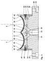
- einen Vakuum-Gehäuse-Einsatz nach der Erfindung im Querschnitt,
- Fig. 4
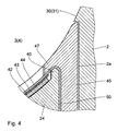
- eine Teil-Darstellung aus
Fig. 3 in vergrößertem Maßstab, - Fig. 5
- eine perspektivische Darstellung eines Vakuum-Gehäuse-Einsatzes,
- Fig. 6
- einen Vakuum-Gehäuse-Einsatz in Explosionsdarstellung,
- Fig. 7
- eine abgewandelte Ausführungsform eines Vakuum-Gehäuse-Einsatzes in Explosionsdarstellung und
- Fig. 8
- eine Extruder-Anlage mit einer vorgeordneten Fütter-Schnecken-Maschine im vertikalen Längsschnitt.
- Die in
Fig. 1 und2 dargestellte Extruder-Anlage weist eine als Extruder 1 ausgebildete Schnecken-Maschine auf. In dessen in der üblicherweise aus mehreren Gehäuseschüssen bestehendem Gehäuse 2 sind achtförmig ineinandergreifende Gehäuse-Bohrungen 3, 4 ausgebildet, deren Achsen 5, 6 parallel zueinander verlaufen. In den Gehäuse-Bohrungen 3, 4 sind zwei Schnecken 7, 8 angeordnet. Die Schnecken sind als gleichsinnig drehende dicht kämmende Schnecken 7, 8 ausgebildet. An einem - inFig. 1 und2 linken - Ende mündet ein Zufuhr-Trichter 9 in die Bohrungen 3, 4 ein. Ausgehend von dem Zuführ-Trichter 9 sind in Förderrichtung 10 die Schnecken 7, 8 mit einem ersten Förder-Schnecken-Abschnitt 11, daran anschließend einem Knet-Scheiben-Abschnitt 12 und wieder einem zweiten Förder-Schnecken-Abschnitt 13 versehen. - Der erste Förder-Schnecken-Abschnitt 11 erstreckt sich über eine als Feststoff-Förderzone wirkende Einzugs-Zone 14. Der Knet-Scheiben-Abschnitt 12 definiert hier eine Aufschmelz-Zone 15. Der zweite Förder-Schnecken-Abschnitt 13 definiert eine Druckaufbau-Zone 16. An die Druckaufbau-Zone 16 schließt am Ende des Gehäuses 2 eine Austritts-Düse 17 an. Wie weiterhin der Zeichnung entnehmbar ist, ist das Gehäuse 2 in einem begrenzten Abschnitt der Einzugs-Zone 14 mit Kühlkanälen 18 versehen.
- Der Antrieb der Schnecken 7, 8 erfolgt mittels eines Elektro-Motors 19, der über eine Kupplung 20 mit einem Untersetzungs- und Verteiler-Getriebe 21 antriebsmäßig verbunden ist. An das Getriebe 21 sind wiederum die Schnecken 7, 8 in üblicher Weise angekoppelt. Oberhalb des Zuführ-Trichters 9 ist eine Dosier-Einrichtung 22 angeordnet, die beispielsweise als gravimetrische Dosier-Schnecke ausgebildet ist.
- Mit geringem Abstand, aber im Abstand hinter dem Zuführ-Trichter 9 weist das Gehäuse 2 einen Vakuum-Gehäuse-Einsatz 23 auf, der sich also über einen Teilabschnitt der Einzugs-Zone 14 erstreckt und der in eine angepasste Öffnung 2a im Gehäuse 2 ausgebildet ist. Der Vakuum-Gehäuse-Einsatz 23 weist einen blockförmigen Grundkörper 24 auf, der auf einer Seite mit einem umlaufenden Flansch 25 versehen ist, in dem Bohrungen 26 zur Befestigung mittels Schrauben 27 am Gehäuse 2 ausgebildet sind. An seiner dem Flansch 25 abgewandten Seite ist der Grundkörper 24 mit zwei etwa teilzylindrischen Auflageflächen 28, 29 versehen, die im Wesentlichen der Krümmung der Innenwände 30, 31 der Bohrungen 3, 4 entsprechen und an ihrer Durchdringungsstelle einen Zwickel 32 bilden.
- Im blockförmigen Grundkörper 24 ist ein zentraler Vakuum-Kanal 33 ausgebildet, der mittels je eines Verzweigungs-Kanals 34, 35 in jeder Auflage-Fläche 28, 29 mündet. In den Auflage-Flächen 28, 29 können noch in Form offener Nuten ausgebildete Vakuum-Verteilungs-Kanäle 36 ausgebildet sein.
- Außerdem sind benachbart zu den Auflage-Flächen 28, 29 im Grundkörper 24 noch Kühl-Kanäle 37 ausgebildet, die über einen Kühlmittel-Zuführ-Anschluss 38 im Flansch 25 mit Kühlmittel versorgt werden, das über einen Kühlmittel-Abführ-Anschluss 39 im Flansch 25 wieder abgeführt wird.
- Die Auflage-Flächen 28, 29 sind durch parallel zu den Achsen 5, 6 der Bohrungen 3, 4 verlaufende geradlinige Rand-Stege 40 und durch der Krümmung der Auflage-Flächen 28, 29 folgende gekrümmte Rand-Stege 41 begrenzt, wobei die Rand-Stege 40, 41 um ein geringes Maß gegenüber den Auflage-Flächen 28, 29 hochragen.
- Zwischen die Rand-Stege 40, 41 ist auf die Auflage-Flächen 28, 29 ein entsprechend dem doppelt gekrümmten Verlauf der Auflage-Flächen 28, 29 gekrümmtes Drainage-Gewebe 42 mit grober Maschenweite, beispielsweise einer Maschenweite von 800 µm und einer Dicke von beispielsweise 1,0 mm aufweist, aufgelegt. Allgemein gilt, dass das Drainage-Gewebe 42 eine Maschenweite im Bereich von 500 µm bis 1000 µm hat. Auf diesem Drainage-Gewebe 42 liegt ein Stütz-Gewebe 43 mit einer feineren Maschenweite von beispielsweise etwa 300 µm. Allgemein gilt, dass das Stütz-Gewebe 43 eine Maschenweite im Bereich von 100 µm bis 400 µm aufweist. Die Dicke ist beispielsweise im Bereich von 0,4 mm. Auf diesem Stützgewebe 43 ist schließlich ein dünnes Metall-Vlies 44 angeordnet, das eine sehr hohe Porösität bei Filterfeinheiten gemäß ISO16889 von 3 µm bis 10 µm aufweist. Allgemein gilt, dass die Filterfeinheit des Metall-Vlieses 44 von 1 µm bis 10 µm geht. Die Dicke des Metall-Vlieses 44 liegt hierbei im Bereich von 0,3 mm bis 0,5 mm. Unter einem Vlies versteht man eine Schicht aus aneinander haftenden im Wesentlichen geraden, ungeordneten Fasern, die also nicht durch Weben oder Wirken miteinander verbunden sind.
- Während das Drainage-Gewebe 42 und das Stütz-Gewebe 43 auf den Auflage-Flächen 28, 29 zwischen den Rand-Stegen 40, 41 liegen, liegt das Metall-Vlies 44 auf diesen Rand-Stegen 40, 41 auf.
- Die Befestigung des Drainage-Gewebes 42, des Stütz-Gewebes 43 und des Metall-Vlieses 44 erfolgt durch Leisten 45, 46. Die Leisten 45, 46 sind etwa L-förmig ausgebildet, d. h. sie weisen einen quer vorspringenden Klemm-Steg 47 bzw. 48 auf. Die Leisten 45 weisen einen geradlinigen Klemm-Steg 47 auf, der den Rand-Stegen 40 zugeordnet ist. Die Leisten 46 weisen doppelt gekrümmte Klemm-Stege 48 auf, die den gekrümmten Rand-Stegen 41 entsprechen. Wie den
Fig. 3 bis 5 und den Explosionsdarstellungen gemäßFig. 6 und7 entnehmbar ist, wird das Metall-Vlies 44 mittels der Leisten 45, 46 rundum auf den Rand-Stegen 40, 41 mittels der Klemm-Stege 47, 48 fest eingespannt. Die Leisten 45, 46 werden mittels Schrauben 49 am Grundkörper 24 befestigt. Das Metall-Vlies 44 wird hierbei rundum fest zwischen den Rand-Stegen 40, 41 und den Klemm-Stegen 47, 48 unter Zusammenpressung eingespannt. Zweckmäßigerweise weist das Metall-Vlies 44 noch zusätzliche Klemm-Abschnitte 50 auf, die über die geradlinigen Rand-Stege 40 nach unten gebogen sind und zwischen den Leisten 45 und dem Grundkörper 24 geklemmt werden, wobei die zugeordneten Schrauben 49 auch noch Löcher 51 in diesen Klemm-Abschnitten 50 durchsetzen, wie den Explosionsdarstellungen nachFig. 6 und7 entnehmbar ist. - Alternativ können die Halte-Leisten 45', 46' auch zu einem Halte-Rahmen 52 verbunden sein, wobei sie entweder von vornherein insgesamt einstückig ausgebildet werden, oder durch Verschweißen oder dergleichen miteinander verbunden werden. Dies ist der Explosionsdarstellung nach
Fig. 7 zu entnehmen. - Der Vakuum-Kanal 33 ist über eine Vakuum-Leitung 53 an eine Vakuum-Quelle 54, beispielsweise eine Wasserring-Pumpe, angeschlossen. In der Vakuum-Leitung 53 ist ein Vakuum-Steuer-Ventil 55 vorgesehen. Des Weiteren ist zwischen der Vakuum-Quelle 54 und dem Ventil 55 ein Druck-Mess-Gerät 56 vorgesehen. In den Vakuum-Kanal 33 mündet weiterhin eine Druck-Spül-Leitung 57 ein, die an eine Druckgas-Quelle 58 angeschlossen ist. In diese Druck-Spül-Leitung 57 ist ein Spül-Ventil 59 eingebaut. Das Druck-Mess-Gerät 56 gibt über eine Signal-Leitung 60 Mess-Signale, die dem jeweils in der Vakuum-Leitung 53 gemessenen Druck entsprechen, auf eine zentrale Steuerung 61. Von der zentralen Steuerung 61 wird wiederum das Vakuum-Steuer-Ventil 55 über eine Vakuum-Steuer-Leitung 62 angesteuert. Des Weiteren wird von der Steuerung 61 über eine Leitung 63 das Spül-Ventil 59 angesteuert. Schließlich werden von der Steuerung 61 auch der Antriebs-Motor 64 der Dosier-Einrichtung 22, der Antriebs-Motor 19 des Extruders 1 und der Motor 65 der Vakuum-Quelle 54 angesteuert. Wenn der Druck in der Vakuum-Leitung 53 einen vorgegebenen Wert unterschreitet, dann ist dies ein Anzeichen dafür, dass das Metall-Vlies 44 einen vorgegebenen zulässigen Verstopfungswert überschritten hat. Dann werden das Vakuum-Steuer-Ventil 55 geschlossen und die Motoren 19, 64, 65 abgeschaltet. Gleichzeitig wird das Spül-Ventil 59 geöffnet, so dass ein Druckgasstoß von der Druckgas-Quelle 58 durch den Vakuum-Kanal 33 gegeben wird, der zu einer entsprechenden Reinigung des Metall-Vlieses 44 führt.
- Wenn dagegen mit einer einfachen Rückspülung das Metall-Vlies 44 nicht mehr ausreichend gereinigt werden kann, dann kann es in sehr einfacher Weise ausgewechselt werden, und zwar durch Lösen der Schrauben 27 und Herausziehen des Vakuum-Gehäuse-Einsatzes 23 aus dem Gehäuse 2. Anschließend werden die Schrauben 49 gelöst, so dass die Halte-Leisten 45, 46 bzw. die zu einem Halte-Rahmen 52 verbundenen Halte-Leisten 45', 46' abgenommen werden können. Das Metall-Vlies 44 wird ausgetauscht. Der Einsatz 23 wird wieder zusammengesetzt und in das Gehäuse 2 des Extruders 1 eingefügt. Zwischen dem Flansch 25 des Vakuum-Gehäuse-Einsatzes 23 und dem Gehäuse 2 kann eine Dichtung 66 angeordnet sein. Wie aus der Zeichnung ersichtlich ist, liegen die Klemm-Stege 47, 48 bündig mit der jeweiligen Innenwand 30 bzw. 31 der Bohrungen 3, 4. Dies bedeutet, dass das Metall-Vlies 44 einen Spalt 67 gegenüber den Schnecken-Stegen 68 der Schnecken 7, 8 begrenzt.
- Bei der Ausgestaltung einer Extruder-Anlage nach
Fig. 8 werden die aufzubereitenden Schüttgüter dem Extruder 1 nicht mittels der Dosier-Einrichtung 22 über einen Zuführ-Trichter zugeführt, sondern mittels einer Zuführ-Schnecken-Maschine 69. Diese weist ein Gehäuse 70 auf, in dem ein oder zwei Bohrungen 71 ausgebildet sind, die jeweils Achsen 72 aufweisen. In jeder Gehäuse-Bohrung 71 ist eine Schnecke 73 angeordnet. An einem - inFig. 8 linken - Ende mündet ein Zuführ-Trichter 74 in die mindestens eine Bohrung 71 ein. Die Schnecke 73 ist als reine Förderschnecke ausgebildet, wobei bei Vorhandensein von zwei Schnecken 73 diese als gleichsinnig drehende, dicht kämmende Förderschnecken ausgebildet sind. Im Bereich der Schnecken-Spitze 75 ist ein Gehäuse-Auslass 76 ausgebildet, der in den nachgeordneten Extruder 1 einmündet, in den das im Extruder 1 aufzubereitende Material, insbesondere also pulverförmiges Material, wie Polymer oder Zuschlagsstoffe, eingegeben werden. - Der Antrieb der mindestens einen Schnecke 73 erfolgt mittels eines Elektro-Motors 77, der in der üblichen Weise über eine Kupplung 78 mit einem Untersetzungs-Getriebe 79 antriebsmäßig verbunden ist. An das Getriebe 79 ist wiederum die Schnecke 73 in üblicher Weise angekoppelt, wobei das Getriebe 79 im Fall von zwei Schnecken 73 auch als Verteiler-Getriebe ausgebildet ist. Die Dosier-Einrichtung 22 ist oberhalb des Zuführ-Trichters 74 angeordnet und ist so aufgebaut und arbeitet so, wie es bereits geschildert worden ist.
- Unmittelbar hinter dem Zuführ-Trichter 74 ist im Gehäuse 70 ein oben bereits im Einzelnen geschilderter Vakuum-Gehäuse-Einsatz 23 angeordnet, dessen Versorgung mit Teil-Vakuum und Spülluft in der gleichen Weise erfolgt, wie es bereits für die Extruder-Anlage oben geschildert worden ist.
- Das stark lufthaltige Schüttgut wird in der Zuführ-Schnecken-Maschine 69 über den Vakuum-Gehäuse-Einsatz 23 entlüftet und verdichtet, so dass es dem Extruder 1 bereits in verdichteter Form zugeführt wird. In letzterem braucht in diesem Fall im Extruder 1 keine Entlüftung mehr zu erfolgen.
- Um einer mechanischen Beschädigung des Metall-Vlieses 44, z. B. durch Granulate oder durch Reibung, entgegenzuwirken, kann das Metall-Vlies 44 mittels eines Siebgewebes verstärkt werden. Das Metall-Gewebe ist auf der der jeweiligen Bohrung 3, 4 abgewandten Seite des Metall-Vlieses 44 angebracht.
Claims (15)
- Schnecken-Maschine zur Behandlung von zumindest teilweise pulverförmigem Schüttgut,- mit einem Gehäuse (2; 70),-- das mindestens eine Gehäuse-Bohrung (3, 4; 71) mit einer Innen-Wand (42, 43) aufweist,- mit einer an einem Ende des Gehäuses (2; 70) angeordneten Zuführ-Öffnung (9; 74) für das Schüttgut,- mit jeweils einer in der mindestens einen Gehäuse-Bohrung (3, 4; 71) angeordneten Schnecke (7, 8; 73),- mit einer der Zuführ-Öffnung (9; 74) vorgeordneten Dosier-Einrichtung (22) zur Zuführung des Schüttguts,- mit einem Vakuum-Gehäuse-Abschnitt in der Einzugs-Zone (14), der einen gasdurchlässigen, die mindestens eine Gehäuse-Bohrung (3, 4; 71) begrenzenden Wand-Abschnitt (24) aufweist, und- mit einem Antrieb (19; 77) für die mindestens eine Schnecke (7, 8; 74),
dadurch gekennzeichnet,- dass der Vakuum-Gehäuse-Abschnitt als lösbar im Gehäuse (2; 70) angebrachter Vakuum-Gehäuse-Einsatz (23) ausgebildet ist, in dem ein Metall-Vlies (44) als gasdurchlässiger Wand-Abschnitt an einem Grundkörper (24) auswechselbar gehalten ist. - Schnecken-Maschine nach Anspruch 1, dadurch gekennzeichnet, dass das Metall-Vlies (44) eine Filterfeinheit von 1 µm bis 10 µm aufweist.
- Schnecken-Maschine nach Anspruch 1 oder 2, dadurch gekennzeichnet,
dass das Metall-Vlies (44) über einen gasdurchlässigen Stütz-Körper gegenüber dem Grundkörper (24) abgestützt ist. - Schnecken-Maschine nach Anspruch 3, dadurch gekennzeichnet, dass der Stütz-Körper als Stütz-Gewebe (43) ausgebildet ist.
- Schnecken-Maschine nach einem der Ansprüche 1 bis 4, dadurch gekennzeichnet, dass zwischen dem Stütz-Körper und dem Grundkörper (24) ein gasdurchlässiger Drainage-Körper angeordnet ist.
- Schnecken-Maschine nach Anspruch 5, dadurch gekennzeichnet, dass der Drainage-Körper als Drainage-Gewebe (42) ausgebildet ist.
- Schnecken-Maschine nach Anspruch 4, dadurch gekennzeichnet, dass das Stütz-Gewebe (43) eine Maschenweite im Bereich von 100 µm bis 400 µm aufweist.
- Schnecken-Maschine nach Anspruch 6, dadurch gekennzeichnet, dass das Drainage-Gewebe (42) eine Maschenweite im Bereich von 500 µm bis 1000 µm aufweist.
- Schnecken-Maschine nach einem der Ansprüche 1 bis 8, dadurch gekennzeichnet, dass der Grundkörper (24) mindestens eine der Innen-Wand (30, 31) der mindestens einen Bohrung (3, 4) angepasste teilzylindrische Auflage-Fläche (28, 29) aufweist, gegen die das Metall-Vlies (44) abgestützt ist und
dass am Grundkörper (24) Halte-Leisten (45, 46, 45', 46') lösbar angebracht sind, die das Metall-Vlies (44) klemmend am Grundkörper (24) halten. - Schnecken-Maschine nach Anspruch 9, dadurch gekennzeichnet, dass die Halte-Leisten (45, 46, 45', 46') Klemm-Stege (47, 48) aufweisen, die das Metall-Vlies (44) klemmend gegen den Grundkörper (24) halten.
- Schnecken-Maschine nach einem der Ansprüche 1 bis 10, dadurch
gekennzeichnet,
dass der Grundkörper (24) mit die mindestens eine Auflage-Fläche (28, 29) umgebenden Rand-Stegen (40, 41) versehen ist, zwischen denen der Stütz-Körper und/oder der Drainage-Körper angeordnet sind. - Schnecken-Maschine nach einem der Ansprüche 1 bis 11, dadurch
gekennzeichnet,
dass die Halte-Leisten (45, 46, 45', 46') bündig mit der Innen-Wand (30, 31) der mindestens einen Bohrung (3, 4) angeordnet sind. - Schnecken-Maschine nach einem der Ansprüche 1 bis 12, dadurch
gekennzeichnet,
dass das Metall-Vlies (44) teilweise zwischen dem Grundkörper (24) und mindestens einer Halte-Leiste (45, 45') klemmend gehalten ist. - Schnecken-Maschine nach einem der Ansprüche 1 bis 13, dadurch
gekennzeichnet,
dass die Halte-Leisten (45', 46') als Halte-Rahmen (52) ausgebildet sind. - Schnecken-Maschine nach einem der Ansprüche 1 bis 14, dadurch
gekennzeichnet,
dass das Metall-Vlies (44) mit einem Metall-Gewebe als Verstärkung versehen ist.
Priority Applications (5)
| Application Number | Priority Date | Filing Date | Title |
|---|---|---|---|
| EP09001867A EP2218568B1 (de) | 2009-02-11 | 2009-02-11 | Schnecken-Maschine |
| AT09001867T ATE541691T1 (de) | 2009-02-11 | 2009-02-11 | Schnecken-maschine |
| US12/693,997 US8360627B2 (en) | 2009-02-11 | 2010-01-26 | Screw machine having a vacuum housing insert |
| CN201010113534.7A CN101797795B (zh) | 2009-02-11 | 2010-02-05 | 螺旋式机器 |
| JP2010024049A JP5346833B2 (ja) | 2009-02-11 | 2010-02-05 | スクリュー機械 |
Applications Claiming Priority (1)
| Application Number | Priority Date | Filing Date | Title |
|---|---|---|---|
| EP09001867A EP2218568B1 (de) | 2009-02-11 | 2009-02-11 | Schnecken-Maschine |
Publications (2)
| Publication Number | Publication Date |
|---|---|
| EP2218568A1 true EP2218568A1 (de) | 2010-08-18 |
| EP2218568B1 EP2218568B1 (de) | 2012-01-18 |
Family
ID=40852523
Family Applications (1)
| Application Number | Title | Priority Date | Filing Date |
|---|---|---|---|
| EP09001867A Active EP2218568B1 (de) | 2009-02-11 | 2009-02-11 | Schnecken-Maschine |
Country Status (5)
| Country | Link |
|---|---|
| US (1) | US8360627B2 (de) |
| EP (1) | EP2218568B1 (de) |
| JP (1) | JP5346833B2 (de) |
| CN (1) | CN101797795B (de) |
| AT (1) | ATE541691T1 (de) |
Cited By (10)
| Publication number | Priority date | Publication date | Assignee | Title |
|---|---|---|---|---|
| US20120139147A1 (en) * | 2010-12-01 | 2012-06-07 | Bonnot Company | Apparatus and process for de-airing material in an extruder |
| US20140338534A1 (en) * | 2013-05-15 | 2014-11-20 | Coperion Gmbh | Screw machine and method as well as processing installation for the processing of bulk material |
| EP3053725A1 (de) * | 2015-02-06 | 2016-08-10 | LANXESS Deutschland GmbH | Stopfschnecke |
| WO2016124310A1 (de) * | 2015-02-02 | 2016-08-11 | Entex Rust & Mitschke Gmbh | Extruder mit einer materialaufgabevorrichtung mit entgasungsfilter |
| EP2930004A4 (de) * | 2013-02-21 | 2016-08-31 | Japan Steel Works Ltd | Lüftungsanordnungsvorrichtung für einen doppelschneckenextruder |
| DE102015110983A1 (de) * | 2015-07-07 | 2017-01-12 | Leistritz Extrusionstechnik Gmbh | Verfahren zum Verarbeiten eines ungetrockneten, in Partikelform vorliegenden Polymers oder Polymergemischs mittels eines ein- oder mehrwelligen Extruders |
| EP2810757B1 (de) | 2012-04-27 | 2017-06-21 | The Japan Steel Works, Ltd. | Vorrichtung und verfahren zur schraubenartigen zufuhr von feinpulverrohmaterial |
| DE102017001093A1 (de) | 2016-04-07 | 2017-10-26 | Entex Rust & Mitschke Gmbh | Entgasen bei der Extrusion von Kunststoffen mit Filterscheiben aus Sintermetall |
| DE102019102976A1 (de) | 2019-02-06 | 2020-08-06 | Extricom Extrusion GmbH | SideFeeder mit getrennten Druckbereichen für Entgasung |
| DE102019009152B4 (de) | 2019-02-06 | 2023-02-23 | Extricom Extrusion GmbH | Verfahren zur Aufbereitung von Schüttgut |
Families Citing this family (17)
| Publication number | Priority date | Publication date | Assignee | Title |
|---|---|---|---|---|
| US8094620B2 (en) | 2007-06-26 | 2012-01-10 | Telefonaktiebolaget L M Ericsson (Publ) | System and method for providing voice service in a multimedia mobile network |
| EP2218568B1 (de) * | 2009-02-11 | 2012-01-18 | Coperion GmbH | Schnecken-Maschine |
| ITTO20120403A1 (it) | 2012-05-07 | 2013-11-08 | Maris Flli Spa | Apparecchiatura per il trattamento di materiale polverulento. |
| US20160135253A1 (en) | 2013-06-14 | 2016-05-12 | Basf Se | Heatable molded articles made from electrically conductive thermoplastic polyurethane |
| DE102014002209B4 (de) | 2013-10-11 | 2016-11-24 | Blach Verwaltungs Gmbh & Co. Kg | Vorrichtung zur Seitenstrombeschickung eines Extruders |
| DE202014001484U1 (de) | 2013-10-11 | 2014-04-10 | Extricom Gmbh | SideFeeder mit Rückwärtsentlüftung |
| DE202013009015U1 (de) | 2013-10-11 | 2014-01-27 | Extricom Gmbh | SideFeeder mit Rückwärtsentlüftung und Schneckensteigung |
| US10961062B2 (en) | 2016-06-21 | 2021-03-30 | Golden Renewable Energy, LLC | Bag press feeder assembly |
| CN109563415A (zh) * | 2016-06-21 | 2019-04-02 | 戈登可再生能源有限公司 | 袋压力机进给器组件 |
| CA3028115A1 (en) | 2016-06-21 | 2017-12-28 | Golden Renewable Energy, LLC | Char separator and method |
| CN109477010B (zh) | 2016-07-05 | 2021-07-23 | 戈登可再生能源有限公司 | 用于将废弃塑料转化成燃料的系统和工艺 |
| JP2019529763A (ja) * | 2017-04-05 | 2019-10-17 | ゴールデン リニューアブル エナジー、エルエルシー | 袋用プレス・フィーダ組立体 |
| DE112019001669B4 (de) | 2018-03-29 | 2025-01-30 | Entek Manufacturing, LLC | Mehrschneckenextruder, der mit einem Unterdruckentlüftungsloch und Schnecken implementiert wird, die dazu eingerichtet sind, durch den Extruder verarbeitetes Material zu verdichten oder Fluid aus diesem zu extrahieren und Verfahren |
| JP7092832B2 (ja) * | 2020-08-24 | 2022-06-28 | 芝浦機械株式会社 | スクリュ機械 |
| CN112317730B (zh) * | 2020-10-14 | 2021-11-30 | 常熟市鑫美金属制品厂 | 一种全自动金属制品成型设备 |
| EP4227064B1 (de) | 2022-02-10 | 2024-10-23 | Feddem GmbH & Co. KG | Extruder mit filterelement |
| CN117656419A (zh) * | 2023-12-26 | 2024-03-08 | 宁波方力科技股份有限公司 | 一种排气式塑料熔体混合器 |
Citations (8)
| Publication number | Priority date | Publication date | Assignee | Title |
|---|---|---|---|---|
| DE1729395B1 (de) | 1968-01-15 | 1971-12-09 | Werner & Pfleiderer | Schneckenstrangpresse |
| GB1277150A (en) | 1969-10-09 | 1972-06-07 | Upjohn Co | Improvements in or relating to antibiotics and the manufacture thereof |
| US4578455A (en) * | 1983-03-24 | 1986-03-25 | Basf Aktiengesellschaft | Process and apparatus for removing volatile constituents from polymer melts or pastes |
| DE19516082A1 (de) | 1995-05-03 | 1996-11-07 | Gerhard Prof Dipl Ing Vetter | Gehäuse von feststoffördernden Schnecken mit Öffnungen |
| US5651808A (en) | 1989-11-09 | 1997-07-29 | Rutgers, The State University Of New Jersey | Carbothermic reaction process for making nanophase WC-Co powders |
| EP1400337A1 (de) * | 2002-09-20 | 2004-03-24 | Basf Aktiengesellschaft | Vorrichtung zum Extrudieren von Thermoplasten |
| EP1977877A1 (de) | 2007-04-07 | 2008-10-08 | Coperion Werner & Pfleiderer GmbH & Co. KG | Extruder |
| DE202007011767U1 (de) | 2007-08-23 | 2009-01-02 | Coperion Werner & Pfleiderer Gmbh & Co. Kg | Fütter-Schnecken-Maschine |
Family Cites Families (12)
| Publication number | Priority date | Publication date | Assignee | Title |
|---|---|---|---|---|
| US3371379A (en) * | 1965-01-02 | 1968-03-05 | Reifenhauser K G | Apparatus for degassing thermoplastic material in screw presses |
| CH466915A (de) * | 1968-03-08 | 1968-12-31 | Buss Ag | Verfahren zum Behandeln von staub- und pulverförmigen Materialien und Einrichtung zur Ausübung des Verfahrens |
| GB1524088A (en) * | 1976-10-07 | 1978-09-06 | Borovikova S M Lurie E V | Machines for processing polymer compositions by melting |
| US4260264A (en) * | 1979-05-21 | 1981-04-07 | The Japan Steel Works Ltd. | Biaxial vent extruder |
| JP2960885B2 (ja) * | 1996-03-27 | 1999-10-12 | 株式会社日本製鋼所 | スクリュ式混練押出機 |
| JP4001309B2 (ja) * | 1999-09-24 | 2007-10-31 | 株式会社リコー | 粉体の高密度充填方法及び高密度充填装置 |
| JP3712185B2 (ja) * | 2001-01-17 | 2005-11-02 | 株式会社日本製鋼所 | 微粉原料供給装置 |
| JP3689029B2 (ja) * | 2001-09-03 | 2005-08-31 | 株式会社日本製鋼所 | スクリュ式押出機のガス抜き装置 |
| JP4524544B2 (ja) * | 2003-05-12 | 2010-08-18 | 三菱マテリアル株式会社 | 複合金属多孔体およびその製造方法 |
| EP2218568B1 (de) * | 2009-02-11 | 2012-01-18 | Coperion GmbH | Schnecken-Maschine |
| JP5467796B2 (ja) * | 2009-04-24 | 2014-04-09 | 株式会社三和商会 | 押出機のベント装置、及び押出機による混練方法 |
| JP2011224862A (ja) * | 2010-04-20 | 2011-11-10 | Yazaki Corp | ベント孔状態検出装置及び押出機 |
-
2009
- 2009-02-11 EP EP09001867A patent/EP2218568B1/de active Active
- 2009-02-11 AT AT09001867T patent/ATE541691T1/de active
-
2010
- 2010-01-26 US US12/693,997 patent/US8360627B2/en active Active
- 2010-02-05 JP JP2010024049A patent/JP5346833B2/ja active Active
- 2010-02-05 CN CN201010113534.7A patent/CN101797795B/zh active Active
Patent Citations (8)
| Publication number | Priority date | Publication date | Assignee | Title |
|---|---|---|---|---|
| DE1729395B1 (de) | 1968-01-15 | 1971-12-09 | Werner & Pfleiderer | Schneckenstrangpresse |
| GB1277150A (en) | 1969-10-09 | 1972-06-07 | Upjohn Co | Improvements in or relating to antibiotics and the manufacture thereof |
| US4578455A (en) * | 1983-03-24 | 1986-03-25 | Basf Aktiengesellschaft | Process and apparatus for removing volatile constituents from polymer melts or pastes |
| US5651808A (en) | 1989-11-09 | 1997-07-29 | Rutgers, The State University Of New Jersey | Carbothermic reaction process for making nanophase WC-Co powders |
| DE19516082A1 (de) | 1995-05-03 | 1996-11-07 | Gerhard Prof Dipl Ing Vetter | Gehäuse von feststoffördernden Schnecken mit Öffnungen |
| EP1400337A1 (de) * | 2002-09-20 | 2004-03-24 | Basf Aktiengesellschaft | Vorrichtung zum Extrudieren von Thermoplasten |
| EP1977877A1 (de) | 2007-04-07 | 2008-10-08 | Coperion Werner & Pfleiderer GmbH & Co. KG | Extruder |
| DE202007011767U1 (de) | 2007-08-23 | 2009-01-02 | Coperion Werner & Pfleiderer Gmbh & Co. Kg | Fütter-Schnecken-Maschine |
Non-Patent Citations (1)
| Title |
|---|
| DE - GASSING-ZYLINDER: "Plastics Processing Technology News Letter", THE JAPAN STEEL WORKS, LTD. |
Cited By (21)
| Publication number | Priority date | Publication date | Assignee | Title |
|---|---|---|---|---|
| US8992068B2 (en) * | 2010-12-01 | 2015-03-31 | The Bonnot Company | Apparatus for de-airing material in an extruder that includes a vent block |
| US9108354B2 (en) * | 2010-12-01 | 2015-08-18 | The Bonnot Company | Process for de-airing material in an extruder that includes a vent block |
| US20120139147A1 (en) * | 2010-12-01 | 2012-06-07 | Bonnot Company | Apparatus and process for de-airing material in an extruder |
| EP2810757B1 (de) | 2012-04-27 | 2017-06-21 | The Japan Steel Works, Ltd. | Vorrichtung und verfahren zur schraubenartigen zufuhr von feinpulverrohmaterial |
| US9731448B2 (en) | 2013-02-21 | 2017-08-15 | The Japan Steel Works, Ltd. | Vent assembly device for twin-screw extruder |
| EP2930004A4 (de) * | 2013-02-21 | 2016-08-31 | Japan Steel Works Ltd | Lüftungsanordnungsvorrichtung für einen doppelschneckenextruder |
| US20140338534A1 (en) * | 2013-05-15 | 2014-11-20 | Coperion Gmbh | Screw machine and method as well as processing installation for the processing of bulk material |
| DE102013208993A1 (de) | 2013-05-15 | 2014-11-20 | Coperion Gmbh | Schneckenmaschine und Verfahren sowie Aufbereitungsanlage zur Aufbereitung von Schüttgut |
| US9688003B2 (en) | 2013-05-15 | 2017-06-27 | Coperion Gmbh | Screw machine and method as well as processing installation for the processing of bulk material |
| DE102013208993B4 (de) * | 2013-05-15 | 2017-05-11 | Coperion Gmbh | Schneckenmaschine und Verfahren sowie Aufbereitungsanlage zur Aufbereitung von Schüttgut |
| WO2016124310A1 (de) * | 2015-02-02 | 2016-08-11 | Entex Rust & Mitschke Gmbh | Extruder mit einer materialaufgabevorrichtung mit entgasungsfilter |
| EP3053725A1 (de) * | 2015-02-06 | 2016-08-10 | LANXESS Deutschland GmbH | Stopfschnecke |
| WO2016124410A1 (de) * | 2015-02-06 | 2016-08-11 | Arlanxeo Deutschland Gmbh | Stopfschnecke |
| RU2705076C2 (ru) * | 2015-02-06 | 2019-11-01 | Арланксео Дойчланд Гмбх | Уплотнительный червяк |
| EP3253554B1 (de) * | 2015-02-06 | 2022-03-09 | ARLANXEO Deutschland GmbH | Stopfschnecke |
| DE102015110983A1 (de) * | 2015-07-07 | 2017-01-12 | Leistritz Extrusionstechnik Gmbh | Verfahren zum Verarbeiten eines ungetrockneten, in Partikelform vorliegenden Polymers oder Polymergemischs mittels eines ein- oder mehrwelligen Extruders |
| DE102017001093A1 (de) | 2016-04-07 | 2017-10-26 | Entex Rust & Mitschke Gmbh | Entgasen bei der Extrusion von Kunststoffen mit Filterscheiben aus Sintermetall |
| DE102019102976A1 (de) | 2019-02-06 | 2020-08-06 | Extricom Extrusion GmbH | SideFeeder mit getrennten Druckbereichen für Entgasung |
| EP3693150A1 (de) | 2019-02-06 | 2020-08-12 | Extricom Extrusion GmbH | Seitendosierer mit getrennten druckbereichen zur entgasung |
| DE102019009152B4 (de) | 2019-02-06 | 2023-02-23 | Extricom Extrusion GmbH | Verfahren zur Aufbereitung von Schüttgut |
| DE102019102976B4 (de) | 2019-02-06 | 2024-06-20 | Extricom Extrusion GmbH | Schneckenmaschine mit Einzugsgehäuse und Entgasungsgehäuse |
Also Published As
| Publication number | Publication date |
|---|---|
| ATE541691T1 (de) | 2012-02-15 |
| JP5346833B2 (ja) | 2013-11-20 |
| EP2218568B1 (de) | 2012-01-18 |
| JP2010184297A (ja) | 2010-08-26 |
| CN101797795A (zh) | 2010-08-11 |
| CN101797795B (zh) | 2014-04-16 |
| US20100202243A1 (en) | 2010-08-12 |
| US8360627B2 (en) | 2013-01-29 |
Similar Documents
| Publication | Publication Date | Title |
|---|---|---|
| EP2218568B1 (de) | Schnecken-Maschine | |
| EP1977877B1 (de) | Extruder | |
| EP2632686B1 (de) | Vorrichtung zum filtrieren einer kunststoffschmelze | |
| DE102012217586A1 (de) | Spritzgießanlage und Spritzgießverfahren zur Herstellung von faserverstärkten Kunststoffteilen | |
| EP2576180B1 (de) | Filtriervorrichtung für hochviskose medien | |
| DE10326487A1 (de) | Vorrichtung zur Bereitstellung einer Schmelze | |
| EP2900452B1 (de) | Zuführvorrichtung zur zuführung von fasern bei der herstellung von faserverstärkten kunststoffen | |
| DE10122675B4 (de) | Strangpressvorrichtung für Keramikformprodukte | |
| EP3693150B1 (de) | Seitendosierer mit getrennten druckbereichen zur entgasung | |
| AT413497B (de) | Vorrichtung zum kontinuierlichen filtern von fliessfähigen massen, die feststoffteilchen enthalten | |
| DE202007011767U1 (de) | Fütter-Schnecken-Maschine | |
| EP0540546B1 (de) | Filtriervorrichtung für thermoplastisches kunststoffmaterial | |
| DE102009013386A1 (de) | Doppelschneckenextruder für keramische Masse | |
| DE102014009768B4 (de) | Vorrichtung zum Filtrieren einer Kunststoffschmelze | |
| CH696148A5 (de) | Vorrichtung zum Abscheiden der Transportluft beim Beschicken einer Verarbeitungsmaschine mit Fasermaterial. | |
| WO2018184722A1 (de) | Filteranordnung für ein fluid | |
| DE2940356C2 (de) | ||
| DE102010018419A1 (de) | Siebmühle mit verbesserter Siebhalterung | |
| EP1161293A2 (de) | Reinigungsvorrichtung | |
| WO2014184220A1 (de) | Schmelzefilter mit einer antriebsvorrichtung zur aktiven vorflutung | |
| DE102019009152B4 (de) | Verfahren zur Aufbereitung von Schüttgut | |
| DE29810665U1 (de) | Faserreinigungsaggregat mit Schmutzausscheidungsvorrichtungen | |
| EP4054308B1 (de) | Abscheidevorrichtung zur pneumatischen nachführung körnigen materials | |
| DE69003147T2 (de) | Vorrichtung zur Herstellung von faserigen nichtgewebten Strukturen. | |
| DE102005046286A1 (de) | Verfahren zur Bestimmung von Reinheiten oder Dispersionen einer Polymerschmelze sowie Vorrichtung zur Durchführung des Verfahrens |
Legal Events
| Date | Code | Title | Description |
|---|---|---|---|
| PUAI | Public reference made under article 153(3) epc to a published international application that has entered the european phase |
Free format text: ORIGINAL CODE: 0009012 |
|
| AK | Designated contracting states |
Kind code of ref document: A1 Designated state(s): AT BE BG CH CY CZ DE DK EE ES FI FR GB GR HR HU IE IS IT LI LT LU LV MC MK MT NL NO PL PT RO SE SI SK TR |
|
| AX | Request for extension of the european patent |
Extension state: AL BA RS |
|
| 17P | Request for examination filed |
Effective date: 20100810 |
|
| 17Q | First examination report despatched |
Effective date: 20100907 |
|
| AKX | Designation fees paid |
Designated state(s): AT BE BG CH CY CZ DE DK EE ES FI FR GB GR HR HU IE IS IT LI LT LU LV MC MK MT NL NO PL PT RO SE SI SK TR |
|
| GRAP | Despatch of communication of intention to grant a patent |
Free format text: ORIGINAL CODE: EPIDOSNIGR1 |
|
| GRAS | Grant fee paid |
Free format text: ORIGINAL CODE: EPIDOSNIGR3 |
|
| GRAA | (expected) grant |
Free format text: ORIGINAL CODE: 0009210 |
|
| AK | Designated contracting states |
Kind code of ref document: B1 Designated state(s): AT BE BG CH CY CZ DE DK EE ES FI FR GB GR HR HU IE IS IT LI LT LU LV MC MK MT NL NO PL PT RO SE SI SK TR |
|
| REG | Reference to a national code |
Ref country code: GB Ref legal event code: FG4D Free format text: NOT ENGLISH |
|
| REG | Reference to a national code |
Ref country code: CH Ref legal event code: EP |
|
| REG | Reference to a national code |
Ref country code: AT Ref legal event code: REF Ref document number: 541691 Country of ref document: AT Kind code of ref document: T Effective date: 20120215 Ref country code: IE Ref legal event code: FG4D Free format text: LANGUAGE OF EP DOCUMENT: GERMAN |
|
| REG | Reference to a national code |
Ref country code: DE Ref legal event code: R096 Ref document number: 502009002440 Country of ref document: DE Effective date: 20120315 |
|
| REG | Reference to a national code |
Ref country code: NL Ref legal event code: VDEP Effective date: 20120118 |
|
| LTIE | Lt: invalidation of european patent or patent extension |
Effective date: 20120118 |
|
| PG25 | Lapsed in a contracting state [announced via postgrant information from national office to epo] |
Ref country code: BG Free format text: LAPSE BECAUSE OF FAILURE TO SUBMIT A TRANSLATION OF THE DESCRIPTION OR TO PAY THE FEE WITHIN THE PRESCRIBED TIME-LIMIT Effective date: 20120418 Ref country code: HR Free format text: LAPSE BECAUSE OF FAILURE TO SUBMIT A TRANSLATION OF THE DESCRIPTION OR TO PAY THE FEE WITHIN THE PRESCRIBED TIME-LIMIT Effective date: 20120118 Ref country code: NL Free format text: LAPSE BECAUSE OF FAILURE TO SUBMIT A TRANSLATION OF THE DESCRIPTION OR TO PAY THE FEE WITHIN THE PRESCRIBED TIME-LIMIT Effective date: 20120118 Ref country code: NO Free format text: LAPSE BECAUSE OF FAILURE TO SUBMIT A TRANSLATION OF THE DESCRIPTION OR TO PAY THE FEE WITHIN THE PRESCRIBED TIME-LIMIT Effective date: 20120418 Ref country code: IS Free format text: LAPSE BECAUSE OF FAILURE TO SUBMIT A TRANSLATION OF THE DESCRIPTION OR TO PAY THE FEE WITHIN THE PRESCRIBED TIME-LIMIT Effective date: 20120518 Ref country code: LT Free format text: LAPSE BECAUSE OF FAILURE TO SUBMIT A TRANSLATION OF THE DESCRIPTION OR TO PAY THE FEE WITHIN THE PRESCRIBED TIME-LIMIT Effective date: 20120118 |
|
| REG | Reference to a national code |
Ref country code: IE Ref legal event code: FD4D |
|
| BERE | Be: lapsed |
Owner name: COPERION G.M.B.H. Effective date: 20120228 |
|
| PG25 | Lapsed in a contracting state [announced via postgrant information from national office to epo] |
Ref country code: PL Free format text: LAPSE BECAUSE OF FAILURE TO SUBMIT A TRANSLATION OF THE DESCRIPTION OR TO PAY THE FEE WITHIN THE PRESCRIBED TIME-LIMIT Effective date: 20120118 Ref country code: FI Free format text: LAPSE BECAUSE OF FAILURE TO SUBMIT A TRANSLATION OF THE DESCRIPTION OR TO PAY THE FEE WITHIN THE PRESCRIBED TIME-LIMIT Effective date: 20120118 Ref country code: LV Free format text: LAPSE BECAUSE OF FAILURE TO SUBMIT A TRANSLATION OF THE DESCRIPTION OR TO PAY THE FEE WITHIN THE PRESCRIBED TIME-LIMIT Effective date: 20120118 Ref country code: GR Free format text: LAPSE BECAUSE OF FAILURE TO SUBMIT A TRANSLATION OF THE DESCRIPTION OR TO PAY THE FEE WITHIN THE PRESCRIBED TIME-LIMIT Effective date: 20120419 Ref country code: PT Free format text: LAPSE BECAUSE OF FAILURE TO SUBMIT A TRANSLATION OF THE DESCRIPTION OR TO PAY THE FEE WITHIN THE PRESCRIBED TIME-LIMIT Effective date: 20120518 |
|
| PG25 | Lapsed in a contracting state [announced via postgrant information from national office to epo] |
Ref country code: CY Free format text: LAPSE BECAUSE OF FAILURE TO SUBMIT A TRANSLATION OF THE DESCRIPTION OR TO PAY THE FEE WITHIN THE PRESCRIBED TIME-LIMIT Effective date: 20120118 Ref country code: MC Free format text: LAPSE BECAUSE OF NON-PAYMENT OF DUE FEES Effective date: 20120229 |
|
| PG25 | Lapsed in a contracting state [announced via postgrant information from national office to epo] |
Ref country code: SE Free format text: LAPSE BECAUSE OF FAILURE TO SUBMIT A TRANSLATION OF THE DESCRIPTION OR TO PAY THE FEE WITHIN THE PRESCRIBED TIME-LIMIT Effective date: 20120118 Ref country code: EE Free format text: LAPSE BECAUSE OF FAILURE TO SUBMIT A TRANSLATION OF THE DESCRIPTION OR TO PAY THE FEE WITHIN THE PRESCRIBED TIME-LIMIT Effective date: 20120118 Ref country code: RO Free format text: LAPSE BECAUSE OF FAILURE TO SUBMIT A TRANSLATION OF THE DESCRIPTION OR TO PAY THE FEE WITHIN THE PRESCRIBED TIME-LIMIT Effective date: 20120118 Ref country code: CZ Free format text: LAPSE BECAUSE OF FAILURE TO SUBMIT A TRANSLATION OF THE DESCRIPTION OR TO PAY THE FEE WITHIN THE PRESCRIBED TIME-LIMIT Effective date: 20120118 Ref country code: DK Free format text: LAPSE BECAUSE OF FAILURE TO SUBMIT A TRANSLATION OF THE DESCRIPTION OR TO PAY THE FEE WITHIN THE PRESCRIBED TIME-LIMIT Effective date: 20120118 Ref country code: IE Free format text: LAPSE BECAUSE OF FAILURE TO SUBMIT A TRANSLATION OF THE DESCRIPTION OR TO PAY THE FEE WITHIN THE PRESCRIBED TIME-LIMIT Effective date: 20120118 Ref country code: SI Free format text: LAPSE BECAUSE OF FAILURE TO SUBMIT A TRANSLATION OF THE DESCRIPTION OR TO PAY THE FEE WITHIN THE PRESCRIBED TIME-LIMIT Effective date: 20120118 |
|
| PLBE | No opposition filed within time limit |
Free format text: ORIGINAL CODE: 0009261 |
|
| STAA | Information on the status of an ep patent application or granted ep patent |
Free format text: STATUS: NO OPPOSITION FILED WITHIN TIME LIMIT |
|
| PG25 | Lapsed in a contracting state [announced via postgrant information from national office to epo] |
Ref country code: SK Free format text: LAPSE BECAUSE OF FAILURE TO SUBMIT A TRANSLATION OF THE DESCRIPTION OR TO PAY THE FEE WITHIN THE PRESCRIBED TIME-LIMIT Effective date: 20120118 |
|
| 26N | No opposition filed |
Effective date: 20121019 |
|
| PG25 | Lapsed in a contracting state [announced via postgrant information from national office to epo] |
Ref country code: BE Free format text: LAPSE BECAUSE OF NON-PAYMENT OF DUE FEES Effective date: 20120228 |
|
| REG | Reference to a national code |
Ref country code: DE Ref legal event code: R097 Ref document number: 502009002440 Country of ref document: DE Effective date: 20121019 |
|
| PG25 | Lapsed in a contracting state [announced via postgrant information from national office to epo] |
Ref country code: MK Free format text: LAPSE BECAUSE OF FAILURE TO SUBMIT A TRANSLATION OF THE DESCRIPTION OR TO PAY THE FEE WITHIN THE PRESCRIBED TIME-LIMIT Effective date: 20120118 |
|
| PG25 | Lapsed in a contracting state [announced via postgrant information from national office to epo] |
Ref country code: ES Free format text: LAPSE BECAUSE OF FAILURE TO SUBMIT A TRANSLATION OF THE DESCRIPTION OR TO PAY THE FEE WITHIN THE PRESCRIBED TIME-LIMIT Effective date: 20120429 |
|
| PG25 | Lapsed in a contracting state [announced via postgrant information from national office to epo] |
Ref country code: MT Free format text: LAPSE BECAUSE OF FAILURE TO SUBMIT A TRANSLATION OF THE DESCRIPTION OR TO PAY THE FEE WITHIN THE PRESCRIBED TIME-LIMIT Effective date: 20120118 |
|
| REG | Reference to a national code |
Ref country code: CH Ref legal event code: PL |
|
| PG25 | Lapsed in a contracting state [announced via postgrant information from national office to epo] |
Ref country code: CH Free format text: LAPSE BECAUSE OF NON-PAYMENT OF DUE FEES Effective date: 20130228 Ref country code: LI Free format text: LAPSE BECAUSE OF NON-PAYMENT OF DUE FEES Effective date: 20130228 |
|
| PG25 | Lapsed in a contracting state [announced via postgrant information from national office to epo] |
Ref country code: TR Free format text: LAPSE BECAUSE OF FAILURE TO SUBMIT A TRANSLATION OF THE DESCRIPTION OR TO PAY THE FEE WITHIN THE PRESCRIBED TIME-LIMIT Effective date: 20120118 |
|
| PG25 | Lapsed in a contracting state [announced via postgrant information from national office to epo] |
Ref country code: LU Free format text: LAPSE BECAUSE OF NON-PAYMENT OF DUE FEES Effective date: 20120211 |
|
| PG25 | Lapsed in a contracting state [announced via postgrant information from national office to epo] |
Ref country code: HU Free format text: LAPSE BECAUSE OF FAILURE TO SUBMIT A TRANSLATION OF THE DESCRIPTION OR TO PAY THE FEE WITHIN THE PRESCRIBED TIME-LIMIT Effective date: 20090211 |
|
| REG | Reference to a national code |
Ref country code: FR Ref legal event code: PLFP Year of fee payment: 8 |
|
| REG | Reference to a national code |
Ref country code: FR Ref legal event code: PLFP Year of fee payment: 9 |
|
| REG | Reference to a national code |
Ref country code: FR Ref legal event code: PLFP Year of fee payment: 10 |
|
| REG | Reference to a national code |
Ref country code: DE Ref legal event code: R079 Ref document number: 502009002440 Country of ref document: DE Free format text: PREVIOUS MAIN CLASS: B29C0047580000 Ipc: B29C0048500000 |
|
| PGFP | Annual fee paid to national office [announced via postgrant information from national office to epo] |
Ref country code: GB Payment date: 20260219 Year of fee payment: 18 |
|
| PGFP | Annual fee paid to national office [announced via postgrant information from national office to epo] |
Ref country code: DE Payment date: 20260217 Year of fee payment: 18 |
|
| PGFP | Annual fee paid to national office [announced via postgrant information from national office to epo] |
Ref country code: AT Payment date: 20260216 Year of fee payment: 18 |
|
| PGFP | Annual fee paid to national office [announced via postgrant information from national office to epo] |
Ref country code: IT Payment date: 20260227 Year of fee payment: 18 |
|
| PGFP | Annual fee paid to national office [announced via postgrant information from national office to epo] |
Ref country code: FR Payment date: 20260223 Year of fee payment: 18 |