EP4227064B1 - Extruder mit filterelement - Google Patents
Extruder mit filterelement Download PDFInfo
- Publication number
- EP4227064B1 EP4227064B1 EP22156128.5A EP22156128A EP4227064B1 EP 4227064 B1 EP4227064 B1 EP 4227064B1 EP 22156128 A EP22156128 A EP 22156128A EP 4227064 B1 EP4227064 B1 EP 4227064B1
- Authority
- EP
- European Patent Office
- Prior art keywords
- extruder
- filter element
- support frame
- screw
- filter
- Prior art date
- Legal status (The legal status is an assumption and is not a legal conclusion. Google has not performed a legal analysis and makes no representation as to the accuracy of the status listed.)
- Active
Links
Images


Classifications
-
- B—PERFORMING OPERATIONS; TRANSPORTING
- B29—WORKING OF PLASTICS; WORKING OF SUBSTANCES IN A PLASTIC STATE IN GENERAL
- B29C—SHAPING OR JOINING OF PLASTICS; SHAPING OF MATERIAL IN A PLASTIC STATE, NOT OTHERWISE PROVIDED FOR; AFTER-TREATMENT OF THE SHAPED PRODUCTS, e.g. REPAIRING
- B29C48/00—Extrusion moulding, i.e. expressing the moulding material through a die or nozzle which imparts the desired form; Apparatus therefor
- B29C48/25—Component parts, details or accessories; Auxiliary operations
- B29C48/36—Means for plasticising or homogenising the moulding material or forcing it through the nozzle or die
- B29C48/50—Details of extruders
- B29C48/69—Filters or screens for the moulding material
-
- B—PERFORMING OPERATIONS; TRANSPORTING
- B29—WORKING OF PLASTICS; WORKING OF SUBSTANCES IN A PLASTIC STATE IN GENERAL
- B29B—PREPARATION OR PRETREATMENT OF THE MATERIAL TO BE SHAPED; MAKING GRANULES OR PREFORMS; RECOVERY OF PLASTICS OR OTHER CONSTITUENTS OF WASTE MATERIAL CONTAINING PLASTICS
- B29B7/00—Mixing; Kneading
- B29B7/80—Component parts, details or accessories; Auxiliary operations
- B29B7/84—Venting or degassing ; Removing liquids, e.g. by evaporating components
-
- B—PERFORMING OPERATIONS; TRANSPORTING
- B29—WORKING OF PLASTICS; WORKING OF SUBSTANCES IN A PLASTIC STATE IN GENERAL
- B29C—SHAPING OR JOINING OF PLASTICS; SHAPING OF MATERIAL IN A PLASTIC STATE, NOT OTHERWISE PROVIDED FOR; AFTER-TREATMENT OF THE SHAPED PRODUCTS, e.g. REPAIRING
- B29C48/00—Extrusion moulding, i.e. expressing the moulding material through a die or nozzle which imparts the desired form; Apparatus therefor
- B29C48/25—Component parts, details or accessories; Auxiliary operations
- B29C48/254—Sealing means
- B29C48/2545—Sealing means for filters
-
- B—PERFORMING OPERATIONS; TRANSPORTING
- B29—WORKING OF PLASTICS; WORKING OF SUBSTANCES IN A PLASTIC STATE IN GENERAL
- B29C—SHAPING OR JOINING OF PLASTICS; SHAPING OF MATERIAL IN A PLASTIC STATE, NOT OTHERWISE PROVIDED FOR; AFTER-TREATMENT OF THE SHAPED PRODUCTS, e.g. REPAIRING
- B29C48/00—Extrusion moulding, i.e. expressing the moulding material through a die or nozzle which imparts the desired form; Apparatus therefor
- B29C48/25—Component parts, details or accessories; Auxiliary operations
- B29C48/285—Feeding the extrusion material to the extruder
- B29C48/288—Feeding the extrusion material to the extruder in solid form, e.g. powder or granules
-
- B—PERFORMING OPERATIONS; TRANSPORTING
- B29—WORKING OF PLASTICS; WORKING OF SUBSTANCES IN A PLASTIC STATE IN GENERAL
- B29C—SHAPING OR JOINING OF PLASTICS; SHAPING OF MATERIAL IN A PLASTIC STATE, NOT OTHERWISE PROVIDED FOR; AFTER-TREATMENT OF THE SHAPED PRODUCTS, e.g. REPAIRING
- B29C48/00—Extrusion moulding, i.e. expressing the moulding material through a die or nozzle which imparts the desired form; Apparatus therefor
- B29C48/25—Component parts, details or accessories; Auxiliary operations
- B29C48/285—Feeding the extrusion material to the extruder
- B29C48/297—Feeding the extrusion material to the extruder at several locations, e.g. using several hoppers or using a separate additive feeding
-
- B—PERFORMING OPERATIONS; TRANSPORTING
- B29—WORKING OF PLASTICS; WORKING OF SUBSTANCES IN A PLASTIC STATE IN GENERAL
- B29C—SHAPING OR JOINING OF PLASTICS; SHAPING OF MATERIAL IN A PLASTIC STATE, NOT OTHERWISE PROVIDED FOR; AFTER-TREATMENT OF THE SHAPED PRODUCTS, e.g. REPAIRING
- B29C48/00—Extrusion moulding, i.e. expressing the moulding material through a die or nozzle which imparts the desired form; Apparatus therefor
- B29C48/25—Component parts, details or accessories; Auxiliary operations
- B29C48/36—Means for plasticising or homogenising the moulding material or forcing it through the nozzle or die
- B29C48/50—Details of extruders
- B29C48/76—Venting, drying means; Degassing means
- B29C48/765—Venting, drying means; Degassing means in the extruder apparatus
- B29C48/766—Venting, drying means; Degassing means in the extruder apparatus in screw extruders
- B29C48/767—Venting, drying means; Degassing means in the extruder apparatus in screw extruders through a degassing opening of a barrel
-
- B—PERFORMING OPERATIONS; TRANSPORTING
- B29—WORKING OF PLASTICS; WORKING OF SUBSTANCES IN A PLASTIC STATE IN GENERAL
- B29B—PREPARATION OR PRETREATMENT OF THE MATERIAL TO BE SHAPED; MAKING GRANULES OR PREFORMS; RECOVERY OF PLASTICS OR OTHER CONSTITUENTS OF WASTE MATERIAL CONTAINING PLASTICS
- B29B7/00—Mixing; Kneading
- B29B7/30—Mixing; Kneading continuous, with mechanical mixing or kneading devices
- B29B7/58—Component parts, details or accessories; Auxiliary operations
-
- B—PERFORMING OPERATIONS; TRANSPORTING
- B29—WORKING OF PLASTICS; WORKING OF SUBSTANCES IN A PLASTIC STATE IN GENERAL
- B29C—SHAPING OR JOINING OF PLASTICS; SHAPING OF MATERIAL IN A PLASTIC STATE, NOT OTHERWISE PROVIDED FOR; AFTER-TREATMENT OF THE SHAPED PRODUCTS, e.g. REPAIRING
- B29C48/00—Extrusion moulding, i.e. expressing the moulding material through a die or nozzle which imparts the desired form; Apparatus therefor
- B29C48/25—Component parts, details or accessories; Auxiliary operations
- B29C48/36—Means for plasticising or homogenising the moulding material or forcing it through the nozzle or die
- B29C48/395—Means for plasticising or homogenising the moulding material or forcing it through the nozzle or die using screws surrounded by a cooperating barrel, e.g. single screw extruders
-
- B—PERFORMING OPERATIONS; TRANSPORTING
- B29—WORKING OF PLASTICS; WORKING OF SUBSTANCES IN A PLASTIC STATE IN GENERAL
- B29K—INDEXING SCHEME ASSOCIATED WITH SUBCLASSES B29B, B29C OR B29D, RELATING TO MOULDING MATERIALS OR TO MATERIALS FOR MOULDS, REINFORCEMENTS, FILLERS OR PREFORMED PARTS, e.g. INSERTS
- B29K2105/00—Condition, form or state of moulded material or of the material to be shaped
- B29K2105/06—Condition, form or state of moulded material or of the material to be shaped containing reinforcements, fillers or inserts
- B29K2105/16—Fillers
Definitions
- the invention relates to an extruder for processing powdered bulk material with a filter element according to the preamble of claim 1.
- An extruder for producing and processing polymers usually contains a housing section in its intake area in which a replaceable filter element is accommodated, through which volatile components of powdered bulk material can be extracted.
- a filter element is often designed as a porous plate or as a sieve.
- One problem is often that such a filter element can easily become clogged.
- an extruder is specified that reveals the basic principle of venting the extruder's intake area.
- a vent opening is specified that is provided with a narrow-pitch sieve that is designed as a sintered metal plate.
- the sieve is spaced further away from the screw shaft, which allows a cushion to form that acts as a fine filter.
- the filtering properties of the cushion depend significantly on the grain size and the properties of the powder material. However, the filtering performance decreases as the cushion grows.
- the DE3310676A1 For filtering, a porous plate with pore openings of 5 - 200 ⁇ m in the form of a sintered metal plate and a porosity of 25 - 60% is used, where the plate has a distance to the screw shaft that corresponds to half the distance from the screw shaft to the inside of the extruder housing.
- the EP1400337B1 discloses a degassing opening in an extruder in which a metal wire mesh composite panel with two or more layers is attached, with increasingly tighter mesh layers being located on a coarsely woven, large-mesh carrier layer, with the tightest mesh layer on the product-related side.
- the mesh size of the tightest mesh layer is 1 ⁇ m to 500 ⁇ m.
- the layers of the metal wire mesh composite panel can be sintered.
- the composite panel can be cleaned by backwashing, brushing or annealing.
- the EP2218568B1 discloses an extruder with a degassing opening in which an insert with a filter unit is accommodated, which has a filter fineness of 1 ⁇ m to 10 ⁇ m and is designed as a metal fleece which is supported relative to a base body via a support body and a drainage fabric.
- a filter insert for an extruder in which a protective element is placed in front of the filter element, which has at least two separate protective areas with through-openings, each protective area being assigned a central channel for gas supply in order to enable separate pressure flushing.
- the DE202012001277U1 discloses an extruder for processing powdered bulk material, in which a housing section is formed in the housing of the extruder, in which a filter element arranged on a support frame is accommodated.
- the support frame is detachably attached to the extruder housing.
- the filter element has a filter layer with a mesh size of ⁇ 1 ⁇ m and contains a rear Carrier layer. The filter element can be removed from the housing section using the carrier frame.
- the invention is based on the object of equipping an extruder with a filter element which has a reduced mesh size, which is of simple construction and which does not require regular backflushing of the filter side.
- the invention relates to an extruder of the type specified in the preamble of claim 1.
- the filter element formed from interconnected layers of sintered metal wire sieves preferably has a mesh size of ⁇ 1 ⁇ m in the filter layer, the filter layer being held between a protective layer facing the screw and a rear carrier layer.
- the protective layer is held at a safety distance of 0.5 - 2 mm from the outer diameter of the screw.
- the filter element is attached to a holder and can thus be removed from the gas-permeable wall section.
- the filter element used in the invention preferably consists of only three layers, namely a wide-meshed protective layer that prevents damage to the actual filter layer, especially if this has an extremely small mesh size of less than 1 ⁇ m and is correspondingly sensitive.
- the back of the filter layer is provided with a carrier layer to stabilize the filter unit.
- the connection of the layers and the construction of the filter element of the layers are achieved by sintering the layers themselves and by connecting them to one another.
- the filter element formed from the specified layers is self-supporting and dimensionally stable. In order to be able to remove it from the extruder housing for maintenance, it can be removed from the gas-permeable wall section by removing the holder that supports the filter element.
- the radial position of the holder in the extruder housing relative to the screw is preferably adjustable.
- the adjustability can be achieved by making the holder adjustable by means of an adjustable screw connection between the holder and a cover plate detachably attached to the extruder housing.
- the filter element is preferably screwed or clamped to the holder using fastening strips.
- the fastening strips are used to fix the filter element in place and to compress a seal between the filter element and the holder to prevent the filter element from warping and shifting due to high shear forces during operation of the extruder.
- the fastening strips also allow the filter element to be easily separated from the holder.
- a self-supporting clamping frame that holds the filter element without screw fastening can also be provided.
- the gases flowing through the filter layer are preferably extracted via a hole in the screw connection, to which an extraction channel can be flanged via a coupling.
- the hole in the screw connection leads into a cavity in the holder on the back of the filter layer.
- the holder preferably has a circumferential seal. It is also possible to Flat seals extending around the entire housing section must be provided between the bracket and the filter layer in order to create a gas-tight seal there as well.
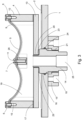
- the essentially cuboid-shaped insert element shown is designed such that it can be inserted into a housing section of the intake area of an extruder. It has a cover plate 1 provided with a gas passage, which can either be fastened to an edge section of the gas-permeable wall section of the extruder housing by means of a screw connection via corner drill holes 3, or which rests on a recessed shoulder in the wall area of the wall section and is fastened thereto by means of screws, whereby the surface of the cover plate can run in the plane of the outside of the extruder housing.
- the screw connection 14 shown in detail connects the cover plate 1 to a support frame 4 via a filter cover 13.
- the support frame 4 has double-curved side walls on the front side for a twin-screw extruder, the arched shape of which represents partial arches that run concentrically to the circumference of two screws arranged in a double extruder.
- the front side of the filter element 5 facing the screws lies in the radial direction of the screws via a seal 9 on the edge of the curved side walls and in the axial direction of the screws on straight edge sections of the support frame 4 and is fastened to the support frame 4 by means of clamping strips 6, 7, 8.
- the filter structure fits closely to the circumference of the screws.
- FIG 2 shows an exploded view of the insert element for insertion into an extruder housing.
- the cover plate 1 has a central bore 16 in which there is an annular seal 24 which is directed against a smooth cylindrical area 22 of the screw connection 14 which is guided through the bore 16.
- the front end of the screw connection 14 has an external thread 23 via which the screw connection 14 can be screwed into an internal thread 20 of a plate-shaped filter cover 13 which forms the rear part of the support frame 4.
- the thread 23 of the screw connection 14 is followed by the enlarged shoulder 22, on which the cover plate 1 placed on it can be moved in the axial direction.
- a flat seal 29 is located on the front side of the shoulder 22.
- An external thread 21 is formed in the axially central area of the screw connection 14.
- the axial position of the screw connection 14 and thus the position of the filter unit, which comprises the filter cover, the support frame and the filter element, can be locked relative to the cover plate 1 in relation to the screws.
- This can be achieved by fixing the lock nut 15 relative to the cover plate 1 using clamping screws which are guided through slots 18 running in the circumferential direction of the lock nut 15 through the lock nut 15 and screwed into the cover plate 1. If the If the clamping screws are loosened again, the lock nut can be turned and thus the position of the entire filter unit with respect to the cover plate 1 can be changed.
- guide pins attached to the cover plate 1 or the support frame 4 can be used, which are inserted into blind holes in the opposite support frame 4 or the cover plate 1.
- the screw connection 14 is designed as a hollow screw with a bore 25.
- a quick-release coupling of a gas discharge channel or hose can be flanged to the bore 25 on the outside of the screw connection.
- the front open end of the screw connection 14 projects into the interior 19 of the support frame 4, so that a gas guide channel is formed via the screw connection 14 into the interior 19 of the support frame.
- the ring seal 24 and the flat seals 2 and 17 serve to seal the interior of the filter element against the ambient air of the extruder.
- the flat seal 17 is arranged between the filter cover 13 and the support frame 4.
- the support frame is formed from two longitudinal walls and two transverse walls, wherein the transverse walls have double-curved end surfaces for a twin-shaft extruder and single-curved end surfaces for a single-shaft extruder, while the longitudinal walls are essentially rectangular with flat end surfaces.
- the filter element which has a shape corresponding to the surrounding surfaces, is applied to the surrounding surfaces of the support frame 4. It is fastened to the surfaces with the aid of screws which are guided through the longitudinal clamping strips 6, 7, 8 into blind holes 10, 11, 12 in the side walls or a central web 26.
- a flat seal 9 following the shape of the filter element 5 is provided between the filter element 5 and the front surfaces of the support frame 4.
- the cavity 19 between the back of the filter element 5, the inner sides of the support frame 4 and the filter cover 13 is directly connected to an extraction channel via the bore 25 in the screw connection 14, so that gases entering the cavity 19 via the filter element 5 can be easily extracted.
- the filter element is designed to be self-supporting and rigid. It essentially contains three layers, namely a front-side securing layer 27, a filter layer 28 and a rear-side carrier layer. All three layers are designed as sintered metal sieve layers, with the filter layer 28 having a mesh size of ⁇ 1 ⁇ m, preferably 0.5 ⁇ m.
- the securing layer 27 has a mesh size of approximately 20 - 100 times that of the filter layer 28, while the carrier layer preferably also has a mesh size of 20 - 100 ⁇ m.
- the carrier layer can also be formed from several layers with different mesh sizes sintered together.
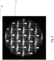
- Figure 4 shows a microscopic image of the filter element, which shows the securing layer 27 and the filter layer 28 underneath.
- the thickness of the securing layer 27 is so small that the filter layer 28 can be arranged at a distance of 0.5 - 2 mm from the outer circumference of the screws. This ensures that practically no filter cake can form between the filter layer and the outer circumference of the screws. This means that neither a pressure pulse through the filter layer to break down a filter cake nor brushing is necessary. This increases the service life of the extruder and avoids downtime.
- the invention is not limited to use on twin-screw extruders, but can also be used in the same way on single-screw extruders if the shape is adapted.
Landscapes
- Engineering & Computer Science (AREA)
- Mechanical Engineering (AREA)
- Extrusion Moulding Of Plastics Or The Like (AREA)
- Filtering Materials (AREA)
- Filtering Of Dispersed Particles In Gases (AREA)
Description
- Die Erfindung betrifft einen Extruder zur Verarbeitung von pulverförmigem Schüttgut mit einem Filterelement nach dem Oberbegriff des Anspruchs 1.
- Ein Extruder zum Herstellen und Verarbeiten von Polymeren enthält in seinem Einzugsbereich in der Regel einen Gehäuseabschnitt, in dem ein austauschbares Filterelement aufgenommen ist, über das flüchtige Anteile von pulverförmig zugeführtem Schüttgut abgesaugt werden können. Ein solches Filterelement ist häufig als poröse Platte oder als Sieb ausgeführt. Ein Problem besteht häufig darin, dass ein solches Filterelement leicht verstopfen kann.
- Ein Lösungsansatz besteht darin, über einen Absaugkanal des gasdurchlässigen Gehäuseabschnitts, aus dem die flüchtigen Anteile abgesaugt werden, einen umgekehrten Gasdruck-Stoß auf das Filterelement auszuüben, um die gegen die Schneckenwelle(n) des Extruders gerichtete Vorderseite des Filterelements von dem dort abgelagerten Pulverkuchen zu befreien. Eine weitere Möglichkeit besteht darin, den Pulverkuchen mechanisch abzutragen, was jedoch nur in Produktionspausen möglich ist.
- In der
DE1729395B ist ein Extruder angegeben, der das Grundprinzip einer Entlüftung des Einzugsbereichs des Extruders offenbart. Dort ist eine Entlüftungsöffnung angegeben, die mit einem Sieb mit enger Teilung versehen ist, das als Sintermetallplatte ausgebildet ist. Zur Vermeidung, dass Pulver aus der Entlüftungsöffnung hinausgesaugt wird, weist das Sieb einen größeren Abstand von der Schneckenwelle auf, wodurch sich ein Polster ausbilden kann, das als Feinstfilter wirkt. Die Filtereigenschaft des Polsters hängt dabei erheblich von der Korngröße und den Eigenschaften des Pulvermaterials ab. Mit anwachsendem Polster verringert sich aber die Filterleistung. - Die
DE3310676A1 nennt zur Filterung eine poröse Platte mit Porenöffnungen von 5 - 200 µm in Form einer Sintermetallplatte und einer Porosität von 25 - 60 %, bei dem die Platte einen Abstand zur Schneckenwelle aufweist, der der Hälfte des Abstands von Schneckenwelle zur Innenseite des Extruder-Gehäuses entspricht. - In der
DE202007011767U1 bzw. derEP1977877B1 ist ein Extruder angegeben, bei dem eine Entgasungsöffnung vorgesehen ist, die mit einem aus Sintermetall gebildeten Filterelement versehen ist, das unter Bildung eines Spalts mit einer Dicke von 2 mm - 30 mm von der Schneckenwelle beabstandet ist. Der sich in dem Spalt aufbauende Filterkuchen lässt sich hier über einen durch eine Druck-Spül-Leitung zugeführten Druckimpuls entfernen. - Die
EP1400337B1 offenbart eine Entgasungsöffnung in einem Extruder, in der eine Metalldrahtgewebe-Verbundplatte mit zwei oder mehr Lagen befestigt ist, wobei sich auf einer grob gewebten, großmaschigen Trägerschicht immer engmaschigere Lagen, mit der engmaschigsten Lage auf der produktbezogenen Seite, befinden. Die Maschenweite der engmaschigsten Lage beträgt 1 µm bis 500 µm. Die Schichten der Metalldrahtgewebe-Verbundplatte können versintert sein. Eine Reinigung der Verbundplatte kann mittels Rückspülen, Abbürsten oder Ausglühen erfolgen. - Die
EP2218568B1 offenbart einen Extruder mit einer Entgasungsöffnung, in der ein Einsatz mit einer Filtereinheit aufgenommen ist, die eine Filterfeinheit von 1 µm bis 10 µm aufweist und als Metall-Vlies ausgebildet ist, das über einen Stützkörper und ein Drainagegewebe gegenüber einem Grundkörper abgestützt ist. - In der
DE102013208993B4 ist ein Filtereinsatz für einen Extruder angegeben, bei dem dem Filterelement ein Schutzelement vorgesetzt ist, das mindestens zwei separate Schutzbereiche mit Durchgangsöffnungen aufweist, wobei jedem Schutzbereich ein Zentralkanal zur Gaszuführung zugeordnet ist, um eine getrennte Druckspülung zu ermöglichen. - Die
DE202012001277U1 offenbart einen Extruder zur Verarbeitung von pulverförmigem Schüttgut, bei dem im Gehäuse des Extruders ein Gehäuseabschnitt ausgebildet ist, in dem ein an einem Trägerrahmen angeordnetes Filterelement aufgenommen ist. Der Trägerrahmen ist an dem Extruder-Gehäuse lösbar befestigt. Das Filterelement weist eine Filterschicht mit einer Maschenweite von < 1 µm auf und enthält eine rückseitige Trägerschicht. Mittels des Trägerrahmens kann das Filterelement aus dem Gehäuseabschnitt entfernt werden. - Es besteht Bedarf an weiteren Verbesserungen und Vereinfachungen der Filtereinrichtung eines Extruders.
- Der Erfindung liegt die Aufgabe zugrunde, einen Extruder mit einem Filterelement auszustatten, das eine verkleinerte Maschenweite aufweist, das einfach aufgebaut ist und bei dem keine regelmäßige Rückspülung der Filterseite erforderlich ist.
- Diese Aufgabe wird durch die in den Ansprüchen angegebene Erfindung gelöst. Vorteilhafte Weiterbildungen der Erfindung sind in Unteransprüchen offenbart.
- Die Erfindung geht aus von einem Extruder der im Oberbegriff des Anspruchs 1 angegebenen Art.
- Gemäß der Erfindung weist das aus miteinander verbundenen Schichten von gesinterten Metalldrahtsieben gebildete Filterelement in der Filterschicht vorzugsweise eine Maschenweite von < 1 µm auf, wobei die Filterschicht zwischen einer der Schnecke zugewandten Schutzschicht und einer rückwärtigen Trägerschicht gehalten ist. Die Schutzschicht ist in einem Sicherheitsabstand von 0,5 - 2 mm von dem Außendurchmesser der Schnecke entfernt gehalten. Das Filterelement ist an einer Halterung befestigt und damit aus dem gasdurchlässigen Wandabschnitt entfernbar.
- Das bei der Erfindung verwendete Filterelement besteht vorzugsweise nur aus drei Schichten, nämlich einer weitmaschigen Schutzschicht, die eine Beschädigung der eigentlichen Filterschicht verhindert, insbesondere wenn diese eine extrem kleine Maschenweite von unter 1 µm aufweist und entsprechend empfindlich ist. Die Rückseite der Filterschicht ist mit einer Trägerschicht versehen, um die Filtereinheit zu stabilisieren. Die Verbindung der Schichten und der Aufbau des Filterelements der Schichten sind durch Versinterung der Schichten selbst sowie durch ihre Verbindung untereinander erfolgt.
- Da sich beim Gegenstand der Erfindung kein relevanter Filterkuchen ausbildet, dient das Vorsehen eines Sicherheitsabstandes lediglich der Absicherung gegenüber Toleranzen des Umfangs der Schnecke sowie Toleranzen im Gehäuseaufbau des Extruders.
- Das aus den angegebenen Schichten gebildete Filterelement ist selbsttragend und formstabil ausgebildet. Um es zur Wartung aus dem Extruder-Gehäuse entnehmen zu können, ist es durch Herauslösen der das Filterelement tragenden Halterung aus dem gasdurchlässigen Wandabschnitt entfernbar.
- Die radiale Position der Halterung im Extruder-Gehäuse gegenüber der Schnecke ist vorzugsweise einstellbar ausgebildet. Insbesondere kann die Einstellbarkeit dadurch realisiert werden, dass die Halterung mittels einer einstellbaren Verschraubung zwischen der Halterung und einer an dem Extruder-Gehäuse lösbar befestigten Deckelplatte einstellbar ist.
- Das Filterelement ist an der Halterung vorzugsweise mittels Befestigungsleisten angeschraubt oder angeklemmt. Die Befestigungsleisten dienen der ortsfesten Anordnung des Filterelements und zum Zusammendrücken einer Dichtung zwischen dem Filterelement und der Halterung zur Vermeidung von Verziehen und Verlagern des Filterelements aufgrund hoher Scherkräfte während des Betriebs des Extruders. Die Befestigungsleisten erlauben auch eine einfache Trennung des Filterelements von der Halterung. Alternativ zu Befestigungsleisten oder Klemmleisten kann auch ein das Filterelement aufnehmender selbsttragender Klemmrahmen ohne Schraubenbefestigung vorgesehen sein.
- Die Absaugung der die Filterschicht durchströmenden Gase erfolgt vorzugsweise über eine Bohrung in der Verschraubung, an die über eine Kupplung ein Absaugkanal anflanschbar ist. Die Bohrung der Verschraubung führt in einen Hohlraum in der Halterung auf der Rückseite der Filterschicht.
- Um zu verhindern, dass durch Spalte zwischen Halterung und der Deckelplatte des gasdurchlässigen Gehäuseabschnitts im Extruder-Gehäuse Gase entweichen können, weist die Halterung vorzugsweise eine umlaufende Dichtung auf. Es können auch bis an den umlaufenden Gehäuseabschnitt reichende Flachdichtungen zwischen Halterung und Filterschicht vorgesehen sein, um auch dort eine gasdichte Abdichtung herzustellen.
- Die Erfindung wird nachstehend an Hand eines Ausführungsbeispiels näher erläutert.
- Es zeigen:
- Fig. 1
- eine vereinfachte perspektivische Ansicht eines Einsatzteils zur Aufnahme eines Filterelements,
- Fig. 2
- eine Explosionszeichnung des Einsatzteils,
- Fig. 3
- eine Querschnittsansicht des Einsatzteils, und
- Fig. 4
- eine mikroskopische Ansicht auf die Filterschicht von der oder den Schnecken aus gesehen.
- Ein in
Figur 1 gezeigtes im Wesentlichen quaderförmig ausgeführtes Einsatzelement ist so ausgebildet, dass es in einen Gehäuseabschnitt des Einzugsbereichs eines Extruders einsetzbar ist. Es weist eine mit einem Gasdurchlass versehene Deckelplatte 1 auf, die entweder mittels einer Verschraubung über eckseitige Bohrlöcher 3 auf einem Randabschnitt des gasdurchlässigen Wandabschnitts des Extruder-Gehäuses befestigt werden kann, oder die auf einem rückspringenden Absatz im Wandbereich des Wandabschnitts aufliegt und daran mittels Schrauben befestigt ist, wodurch die Oberfläche der Deckelplatte in der Ebene der Außenseite des Extruder-Gehäuses verlaufen kann. - Zwischen der Deckelplatte 1 und dem Extruder-Gehäuse befindet sich eine Flachdichtung 2 zur Abdichtung der Deckelplatte 1 gegen das Extruder-Gehäuse.
- Eine in den
Figuren 2 und3 im Detail dargestellte Verschraubung 14 verbindet die Deckelplatte 1 über einen Filterdeckel 13 mit einem Trägerrahmen 4. Der Trägerrahmen 4 weist für einen Doppelschnecken-Extruder stirnseitig doppelt gebogene Seitenwände auf, deren Bogenform Teilbögen darstellt, die konzentrisch zum Umfang von zwei in einem Doppelextruder angeordneten Schnecken verlaufen. Die gegen die Schnecken gerichtete Stirnseite des Filterelements 5 liegt in Radialrichtung der Schnecken über eine Dichtung 9 randseitig auf den bogenförmigen Seitenwänden und in Axialrichtung der Schnecken auf geraden Randabschnitten des Trägerrahmens 4 auf und ist mittels Klemmleisten 6, 7, 8 an dem Trägerrahmen 4 befestigt. - Bei Ansetzen des Filterelements an die Schnecken liegt die Filterstruktur eng an dem Umfangsverlauf der Schnecken an.
-
Figur 2 zeigt eine Explosionsansicht des Einsatzelements zum Einsetzen in ein Extruder-Gehäuse. Die Deckelplatte 1 weist eine zentrale Bohrung 16 auf, in der sich eine Ringdichtung 24 befindet, die gegen einen glattzylindrischen Bereich 22 der Verschraubung 14 gerichtet ist, die durch die Bohrung 16 geführt ist. Das vordere Ende der Verschraubung 14 trägt ein Außengewinde 23, über das die Verschraubung 14 in ein Innengewinde 20 eines plattenförmigen Filterdeckels 13, der den rückwärtigen Teil des Trägerrahmens 4 bildet, einschraubbar ist. - An das Gewinde 23 der Verschraubung 14 schließt sich der vergrößerte Absatz 22 an, auf dem der darauf aufgesetzten Deckelplatte 1 in Axialrichtung verschiebbar ist. An der Stirnseite des Absatzes 22 befindet sich eine Flachdichtung 29. Im axial mittleren Bereich der Verschraubung 14 ist ein Außengewinde 21 ausgebildet. Sobald die Verschraubung über das Gewinde 23 an dem Filterdeckel 13 befestigt ist und die Deckelplatte 1 mit der Bohrung 16 auf den vergrößerten Absatz 22 aufgeschoben ist, kann auf das Gewinde 21 eine Kontermutter 15 aufgeschraubt werden, die in Abhängigkeit von der axialen Stellung der Kontermutter auf dem Gewinde 21 die Positionierung des Trägerrahmens 4 in Bezug auf die Deckelplatte 1 ermöglicht.
- Die axiale Position der Verschraubung 14 und damit der Position der Filtereinheit, die den Filterdeckel, den Trägerrahmen und das Filterelement umfasst, lässt sich gegenüber der Deckelplatte 1 in Bezug auf die Schnecken arretieren. Dies lässt sich dadurch erreichen, dass die Kontermutter 15 über Klemmschrauben, die durch in Umfangsrichtung der Kontermutter 15 verlaufende Schlitze 18 durch die Kontermutter 15 geführt und in die Deckelplatte 1 eingeschraubt werden, gegenüber der Deckelplatte 1 fixiert werden kann. Wenn die Klemmschrauben wieder gelöst werden, lässt sich die Kontermutter verdrehen und damit die Position der gesamten Filtereinheit bezüglich der Deckelplatte 1 verändern.
- Zur Verdrehsicherung des Trägerrahmens 4 gegenüber der Deckelplatte 1 können an der Deckelplatte 1 oder dem Trägerrahmen 4 befestigte Führungsstifte verwendet werden, die in Sacklöcher des gegenüberliegenden Trägerrahmens 4 bzw. der Deckelplatte 1 eingeführt sind.
- Die Verschraubung 14 ist als Hohlschraube mit einer Bohrung 25 ausgebildet. An der Außenseite der Verschraubung ist an die Bohrung 25 eine Schnellverschlusskupplung eines Gasabführkanals oder Schlauches anflanschbar.
- Das vordere offene Ende der Verschraubung 14 ragt in den Innenraum 19 des Trägerrahmens 4 hinein, so dass über die Verschraubung 14 ein Gasführungskanal in den Innenraum 19 des Trägerrahmens gebildet ist.
- Zur Abdichtung des Innenraums des Filterelements gegenüber der Umgebungsluft des Extruders dienen die Ringdichtung 24 und die Flachdichtungen 2 und 17.
- Die Flachdichtung 17 ist zwischen Filterdeckel 13 und Trägerrahmen 4 angeordnet. Der Trägerrahmen ist aus zwei Längswänden und zwei Querwänden gebildet, wobei die Querwände für einen Doppelwellen-Extruder doppelt gebogene und für eine Einwellen-Extruder einfach gebogene Stirnseiten-Oberflächen aufweisen, während die Längswände im Wesentlichen rechteckig mit ebenen Stirnseiten-Oberflächen ausgeführt sind.
- Auf die umlaufenden Oberflächen des Trägerrahmens 4 ist das Filterelement, das eine den umlaufenden Oberflächen entsprechende Form aufweist, aufgebracht. Es wird an den Oberflächen mit Hilfe von Schrauben, die durch die längs verlaufenden Klemmleisten 6, 7, 8 in Sacklöcher 10, 11,12 der Seitenwände bzw. eines Mittelstegs 26 geführt sind, befestigt. Zur Abdichtung zwischen Filterelement 5 und Trägerrahmen 4 ist eine der Form des Filterelementes 5 folgende Flachdichtung 9 zwischen dem Filterelement 5 und den stirnseitigen Oberflächen des Trägerrahmens 4 vorgesehen.
- Der Hohlraum 19 zwischen der Rückseite des Filterelements 5, den Innenseiten des Trägerrahmens 4 und dem Filterdeckel 13 steht über die Bohrung 25 in der Verschraubung 14 mit einem Absaugkanal in direkter Verbindung, so dass über das Filterelement 5 in den Hohlraum 19 eintretende Gase problemlos abgesaugt werden können.
- Das Filterelement ist selbsttragend steif ausgebildet. Es enthält im Wesentlichen drei Schichten, nämlich eine vorderseitigen Sicherungsschicht 27, eine Filterschicht 28 und eine rückseitige Trägerschicht. Alle drei Schichten sind als gesinterte Metallsiebschichten ausgebildet, wobei die Filterschicht 28 eine Maschenweite von < 1 µm, vorzugsweise 0,5 µm aufweist. Die Sicherungsschicht 27 weist eine Maschenweite von etwa dem 20 - 100 fachen der Filterschicht 28 auf, während die Trägerschicht vorzugsweise ebenfalls eine Maschenweite von 20 - 100 µm enthält. Die Trägerschicht kann zur Erhöhung der Steifigkeit auch aus mehreren miteinander versinterten Schichten mit unterschiedlicher Maschenweite gebildet sein.
-
Figur 4 zeigt eine mikroskopische Aufnahme des Filterelements, die die Sicherungsschicht 27 und die darunter liegende Filterschicht 28 zeigt. Die Stärke der Sicherungsschicht 27 ist derart klein, dass die Filterschicht 28 in einem Abstand von 0,5 - 2 mm von dem Verlauf des Außenumfangs der Schnecken angeordnet sein kann. Damit wird erreicht, dass sich praktisch kein Filterkuchen zwischen Filterschicht und Außenumfang der Schnecken ausbilden kann. Somit ist auch weder ein Druckimpuls durch die Filterschicht zum Abbau eines Filterkuchens noch ein Abbürsten erforderlich. Dies vergrößert die Standzeit des Extruders und vermeidet Stillstandzeiten. - Eine genaue Abstandseinstellung der Filterschicht 28 gegenüber dem Umfangsverlauf der Schnecken lässt sich durch geeignete Einstellung der Verschraubung 14 erreichen.
- Die Erfindung ist nicht auf den Einsatz an Doppelschnecken-Extrudern beschränkt, sondern kann bei angepasster Form in gleicher Weise auch bei Einfachschnecken-Extrudern verwendet werden.
-
- 1
- Deckelplatte
- 2
- Flachdichtung
- 3
- Bohrung
- 4
- Trägerrahmen
- 5
- Filterelement
- 6
- Klemmleiste
- 7
- Klemmleiste
- 8
- Klemmleiste
- 9
- Flachdichtung
- 10
- Bohrung
- 11
- Bohrung
- 12
- Bohrung
- 13
- Filterdeckel
- 14
- Verschraubung
- 15
- Kontermutter
- 16
- Bohrung
- 17
- Flachdichtung
- 18
- Schlitze
- 19
- Hohlraum
- 20
- Innengewinde
- 21
- Außengewinde
- 22
- Absatz
- 23
- Gewinde
- 24
- Ringdichtung
- 25
- Bohrung
- 26
- Mittelsteg
- 27
- Sicherungsschicht
- 28
- Filterschicht
- 29
- Flachdichtung
Claims (6)
- Extruder zur Verarbeitung von pulverförmigem Schüttgut, mit einem Extruder-Gehäuse, das wenigstens eine axial gerichtete Bohrung mit einer Innenwand und einer in der Bohrung aufgenommenen Schnecke aufweist, wobei in einem Einzugsbereich des Extruder-Gehäuses wenigstens ein Gehäuseabschnitt ausgebildet ist, in dem ein an einem Trägerrahmen (4) angeordnetes Filterelement (5) zur Absaugung gasförmiger Bestandteile des Schüttguts aufgenommen ist, wobei der Trägerrahmen (4) an dem Extruder-Gehäuse lösbar befestigt ist, dadurch gekennzeichnet,- dass das Filterelement (5) aus miteinander verbundenen Schichten von versinterten Metalldrahtsieben gebildet ist,- dass das Filterelement (5) wenigstens eine gegen die Schnecke gerichtete Sicherungsschicht (27) mit einer Maschenweite von 20 - 100 µm, eine Filterschicht (28) mit einer Maschenweite von < 1 µm und eine rückwärtige Trägerschicht enthält, wobei die Sicherungsschicht (27) in einem Sicherheitsabstand von 0,5 - 2 mm von dem Außendurchmesser der Schnecke entfernt angeordnet ist, und- dass das Filterelement (5) mit Hilfe des Trägerrahmens (4) aus dem Gehäuseabschnitt entfernbar ist,wobei das Filterelement (5) selbsttragend und formstabil ausgebildet ist.
- Extruder nach Anspruch 1, dadurch gekennzeichnet, dass die Position des Trägerrahmens (4) im Extruder-Gehäuse radial zu der wenigstens einen Bohrung des Extruders einstellbar ist.
- Extruder nach Anspruch 2, dadurch gekennzeichnet, dass der Trägerrahmen (4) mittels einer einstellbaren Verschraubung (14) zwischen Trägerrahmen (4) und einer an dem Extruder-Gehäuse lösbar befestigten Deckelplatte (1) in Radialrichtung der Extruder-Schnecke oder den Bohrungen für die Extruder-Schnecken einstellbar ist.
- Extruder nach Anspruch 1, dadurch gekennzeichnet, dass das Filterelement (5) mittels in Axialrichtung des Extruders verlaufender Klemmleisten (6, 7, 8) oder einem Klemmrahmen an dem Trägerrahmen (4) befestigt ist.
- Extruder nach Anspruch 3, dadurch gekennzeichnet, dass die Verschraubung (14) eine in Axialrichtung der Verschraubung verlaufende Bohrung (25) zum Anschluss eines Absaugkanals aufweist.
- Extruder nach Anspruch 1, dadurch gekennzeichnet, dass das Filterelement (5) über eine randseitige Dichtung (9) an dem Trägerrahmen (4) befestigt ist.
Priority Applications (10)
| Application Number | Priority Date | Filing Date | Title |
|---|---|---|---|
| PL22156128.5T PL4227064T3 (pl) | 2022-02-10 | 2022-02-10 | Wytłaczarka z elementem filtrującym |
| ES22156128T ES2997559T3 (en) | 2022-02-10 | 2022-02-10 | Extruder with filter element |
| EP22156128.5A EP4227064B1 (de) | 2022-02-10 | 2022-02-10 | Extruder mit filterelement |
| PCT/EP2023/052747 WO2023152058A1 (de) | 2022-02-10 | 2023-02-04 | Extruder mit filterelement |
| CA3248174A CA3248174A1 (en) | 2022-02-10 | 2023-02-04 | EXTRUDER INCLUDING A FILTER ELEMENT |
| KR1020247030121A KR20240142558A (ko) | 2022-02-10 | 2023-02-04 | 필터 요소를 포함하는 압출기 |
| CN202380020894.8A CN118660803A (zh) | 2022-02-10 | 2023-02-04 | 带有过滤器元件的挤出机 |
| MX2024009718A MX2024009718A (es) | 2022-02-10 | 2023-02-04 | Extrusora con elemento filtrante. |
| US18/837,468 US20250162230A1 (en) | 2022-02-10 | 2023-02-04 | Extruder Comprising a Filter Element |
| JP2024547257A JP2025504222A (ja) | 2022-02-10 | 2023-02-04 | フィルター要素を含む押出機 |
Applications Claiming Priority (1)
| Application Number | Priority Date | Filing Date | Title |
|---|---|---|---|
| EP22156128.5A EP4227064B1 (de) | 2022-02-10 | 2022-02-10 | Extruder mit filterelement |
Publications (3)
| Publication Number | Publication Date |
|---|---|
| EP4227064A1 EP4227064A1 (de) | 2023-08-16 |
| EP4227064C0 EP4227064C0 (de) | 2024-10-23 |
| EP4227064B1 true EP4227064B1 (de) | 2024-10-23 |
Family
ID=80447526
Family Applications (1)
| Application Number | Title | Priority Date | Filing Date |
|---|---|---|---|
| EP22156128.5A Active EP4227064B1 (de) | 2022-02-10 | 2022-02-10 | Extruder mit filterelement |
Country Status (10)
| Country | Link |
|---|---|
| US (1) | US20250162230A1 (de) |
| EP (1) | EP4227064B1 (de) |
| JP (1) | JP2025504222A (de) |
| KR (1) | KR20240142558A (de) |
| CN (1) | CN118660803A (de) |
| CA (1) | CA3248174A1 (de) |
| ES (1) | ES2997559T3 (de) |
| MX (1) | MX2024009718A (de) |
| PL (1) | PL4227064T3 (de) |
| WO (1) | WO2023152058A1 (de) |
Family Cites Families (9)
| Publication number | Priority date | Publication date | Assignee | Title |
|---|---|---|---|---|
| DE1729395B1 (de) | 1968-01-15 | 1971-12-09 | Werner & Pfleiderer | Schneckenstrangpresse |
| DE3310676A1 (de) | 1983-03-24 | 1984-09-27 | Basf Ag, 6700 Ludwigshafen | Verfahren und vorrichtung zum entfernen von fluechtigen anteilen aus polymerenschmelzen oder paste |
| ES2290229T3 (es) | 2002-09-20 | 2008-02-16 | Basf Aktiengesellschaft | Aparato y metodo para extrudir termoplasticos y su uso. |
| ATE536981T1 (de) | 2007-04-07 | 2011-12-15 | Coperion Gmbh | Extruder |
| DE202007011767U1 (de) | 2007-08-23 | 2009-01-02 | Coperion Werner & Pfleiderer Gmbh & Co. Kg | Fütter-Schnecken-Maschine |
| ATE541691T1 (de) | 2009-02-11 | 2012-02-15 | Coperion Gmbh | Schnecken-maschine |
| DE202012001277U1 (de) * | 2011-07-29 | 2012-11-07 | Kraussmaffei Berstorff Gmbh | Absaugvorrichtung |
| DE102013208993B4 (de) | 2013-05-15 | 2017-05-11 | Coperion Gmbh | Schneckenmaschine und Verfahren sowie Aufbereitungsanlage zur Aufbereitung von Schüttgut |
| DE202014001484U1 (de) * | 2013-10-11 | 2014-04-10 | Extricom Gmbh | SideFeeder mit Rückwärtsentlüftung |
-
2022
- 2022-02-10 EP EP22156128.5A patent/EP4227064B1/de active Active
- 2022-02-10 PL PL22156128.5T patent/PL4227064T3/pl unknown
- 2022-02-10 ES ES22156128T patent/ES2997559T3/es active Active
-
2023
- 2023-02-04 MX MX2024009718A patent/MX2024009718A/es unknown
- 2023-02-04 WO PCT/EP2023/052747 patent/WO2023152058A1/de not_active Ceased
- 2023-02-04 US US18/837,468 patent/US20250162230A1/en active Pending
- 2023-02-04 KR KR1020247030121A patent/KR20240142558A/ko active Pending
- 2023-02-04 CN CN202380020894.8A patent/CN118660803A/zh active Pending
- 2023-02-04 JP JP2024547257A patent/JP2025504222A/ja active Pending
- 2023-02-04 CA CA3248174A patent/CA3248174A1/en active Pending
Also Published As
| Publication number | Publication date |
|---|---|
| ES2997559T3 (en) | 2025-02-17 |
| MX2024009718A (es) | 2024-08-19 |
| KR20240142558A (ko) | 2024-09-30 |
| EP4227064C0 (de) | 2024-10-23 |
| WO2023152058A1 (de) | 2023-08-17 |
| JP2025504222A (ja) | 2025-02-06 |
| CN118660803A (zh) | 2024-09-17 |
| CA3248174A1 (en) | 2025-07-10 |
| PL4227064T3 (pl) | 2025-03-10 |
| EP4227064A1 (de) | 2023-08-16 |
| US20250162230A1 (en) | 2025-05-22 |
Similar Documents
| Publication | Publication Date | Title |
|---|---|---|
| EP2662124B1 (de) | Trennvorrichtung für rohrförmige Durchflussvorrichtungen | |
| DE2460411C3 (de) | Filterplatte | |
| DE4212928A1 (de) | Filter für Kunststoffschmelzen | |
| EP2218568A1 (de) | Schnecken-Maschine | |
| EP0433587B1 (de) | Siebwechseleinrichtung mit zylinderförmigem Siebkörper | |
| EP0685325B1 (de) | Vorrichtung zum Trennen des Flüssiganteils vom Feststoffanteil von Zweiphasensystemen | |
| EP3000518B1 (de) | Wasserfiltereinrichtung mit rückspülbarem wasserfilter mit fliessgeschwindigkeitsreduktion und verfahren zum rückspülen eines wasserfilters | |
| AT413497B (de) | Vorrichtung zum kontinuierlichen filtern von fliessfähigen massen, die feststoffteilchen enthalten | |
| EP4227064B1 (de) | Extruder mit filterelement | |
| DE2947673C2 (de) | Filtervorrichtung für thermoplastische Formmassen verarbeitende Schneckenextruder | |
| EP3693150B1 (de) | Seitendosierer mit getrennten druckbereichen zur entgasung | |
| DE69407461T2 (de) | Filter zur Filtrierung von geschmolzenem Harz und Filtriereinrichtung zur Bildung mehrschichtigen Harzes | |
| EP0554491B1 (de) | Filterpatrone | |
| EP1504802B1 (de) | Vakkuumfördereinrichtung mit einem mehrstufigen Filtersystem | |
| DE1611068C3 (de) | Rückspülfilter mit zylindrischem Käfig | |
| DE202017007054U1 (de) | Filteranordnung für Fluid | |
| EP0138920B1 (de) | Vorrichtung zum trennen des flüssiganteils vom feststoffanteil eines keramischen schlickers | |
| EP3705164B1 (de) | Leckagemelder für filterelemente | |
| EP1297878A2 (de) | Mehrlagiges Filterelement | |
| DE19951007A1 (de) | Seiherschneckenpresse für Ölsaaten | |
| EP1174244B1 (de) | Vorrichtung zur Abdichtung einer Lochscheibe in einer Extrusionsanlage | |
| WO2003066940A1 (de) | Düsenblock zur herstellung synthetischer fäden und fasern | |
| DE2106077C3 (de) | Röhrenfilterpresse | |
| DE3605065A1 (de) | Separationsvorrichtung | |
| DE102019009152B4 (de) | Verfahren zur Aufbereitung von Schüttgut |
Legal Events
| Date | Code | Title | Description |
|---|---|---|---|
| PUAI | Public reference made under article 153(3) epc to a published international application that has entered the european phase |
Free format text: ORIGINAL CODE: 0009012 |
|
| STAA | Information on the status of an ep patent application or granted ep patent |
Free format text: STATUS: REQUEST FOR EXAMINATION WAS MADE |
|
| 17P | Request for examination filed |
Effective date: 20230615 |
|
| AK | Designated contracting states |
Kind code of ref document: A1 Designated state(s): AL AT BE BG CH CY CZ DE DK EE ES FI FR GB GR HR HU IE IS IT LI LT LU LV MC MK MT NL NO PL PT RO RS SE SI SK SM TR |
|
| GRAP | Despatch of communication of intention to grant a patent |
Free format text: ORIGINAL CODE: EPIDOSNIGR1 |
|
| STAA | Information on the status of an ep patent application or granted ep patent |
Free format text: STATUS: GRANT OF PATENT IS INTENDED |
|
| INTG | Intention to grant announced |
Effective date: 20240607 |
|
| GRAS | Grant fee paid |
Free format text: ORIGINAL CODE: EPIDOSNIGR3 |
|
| GRAA | (expected) grant |
Free format text: ORIGINAL CODE: 0009210 |
|
| STAA | Information on the status of an ep patent application or granted ep patent |
Free format text: STATUS: THE PATENT HAS BEEN GRANTED |
|
| AK | Designated contracting states |
Kind code of ref document: B1 Designated state(s): AL AT BE BG CH CY CZ DE DK EE ES FI FR GB GR HR HU IE IS IT LI LT LU LV MC MK MT NL NO PL PT RO RS SE SI SK SM TR |
|
| REG | Reference to a national code |
Ref country code: GB Ref legal event code: FG4D Free format text: NOT ENGLISH |
|
| REG | Reference to a national code |
Ref country code: CH Ref legal event code: EP |
|
| REG | Reference to a national code |
Ref country code: DE Ref legal event code: R096 Ref document number: 502022001934 Country of ref document: DE |
|
| REG | Reference to a national code |
Ref country code: IE Ref legal event code: FG4D Free format text: LANGUAGE OF EP DOCUMENT: GERMAN |
|
| U01 | Request for unitary effect filed |
Effective date: 20241120 |
|
| U07 | Unitary effect registered |
Designated state(s): AT BE BG DE DK EE FI FR IT LT LU LV MT NL PT RO SE SI Effective date: 20241127 |
|
| REG | Reference to a national code |
Ref country code: ES Ref legal event code: FG2A Ref document number: 2997559 Country of ref document: ES Kind code of ref document: T3 Effective date: 20250217 |
|
| U20 | Renewal fee for the european patent with unitary effect paid |
Year of fee payment: 4 Effective date: 20250228 |
|
| PG25 | Lapsed in a contracting state [announced via postgrant information from national office to epo] |
Ref country code: IS Free format text: LAPSE BECAUSE OF FAILURE TO SUBMIT A TRANSLATION OF THE DESCRIPTION OR TO PAY THE FEE WITHIN THE PRESCRIBED TIME-LIMIT Effective date: 20250223 Ref country code: HR Free format text: LAPSE BECAUSE OF FAILURE TO SUBMIT A TRANSLATION OF THE DESCRIPTION OR TO PAY THE FEE WITHIN THE PRESCRIBED TIME-LIMIT Effective date: 20241023 |
|
| PGFP | Annual fee paid to national office [announced via postgrant information from national office to epo] |
Ref country code: ES Payment date: 20250318 Year of fee payment: 4 |
|
| PG25 | Lapsed in a contracting state [announced via postgrant information from national office to epo] |
Ref country code: NO Free format text: LAPSE BECAUSE OF FAILURE TO SUBMIT A TRANSLATION OF THE DESCRIPTION OR TO PAY THE FEE WITHIN THE PRESCRIBED TIME-LIMIT Effective date: 20250123 |
|
| PG25 | Lapsed in a contracting state [announced via postgrant information from national office to epo] |
Ref country code: GR Free format text: LAPSE BECAUSE OF FAILURE TO SUBMIT A TRANSLATION OF THE DESCRIPTION OR TO PAY THE FEE WITHIN THE PRESCRIBED TIME-LIMIT Effective date: 20250124 |
|
| PGFP | Annual fee paid to national office [announced via postgrant information from national office to epo] |
Ref country code: CH Payment date: 20250301 Year of fee payment: 4 |
|
| PGFP | Annual fee paid to national office [announced via postgrant information from national office to epo] |
Ref country code: PL Payment date: 20250207 Year of fee payment: 4 |
|
| PG25 | Lapsed in a contracting state [announced via postgrant information from national office to epo] |
Ref country code: RS Free format text: LAPSE BECAUSE OF FAILURE TO SUBMIT A TRANSLATION OF THE DESCRIPTION OR TO PAY THE FEE WITHIN THE PRESCRIBED TIME-LIMIT Effective date: 20250123 |
|
| PGFP | Annual fee paid to national office [announced via postgrant information from national office to epo] |
Ref country code: TR Payment date: 20250123 Year of fee payment: 4 |
|
| PG25 | Lapsed in a contracting state [announced via postgrant information from national office to epo] |
Ref country code: SM Free format text: LAPSE BECAUSE OF FAILURE TO SUBMIT A TRANSLATION OF THE DESCRIPTION OR TO PAY THE FEE WITHIN THE PRESCRIBED TIME-LIMIT Effective date: 20241023 |
|
| PG25 | Lapsed in a contracting state [announced via postgrant information from national office to epo] |
Ref country code: SK Free format text: LAPSE BECAUSE OF FAILURE TO SUBMIT A TRANSLATION OF THE DESCRIPTION OR TO PAY THE FEE WITHIN THE PRESCRIBED TIME-LIMIT Effective date: 20241023 |
|
| PG25 | Lapsed in a contracting state [announced via postgrant information from national office to epo] |
Ref country code: CZ Free format text: LAPSE BECAUSE OF FAILURE TO SUBMIT A TRANSLATION OF THE DESCRIPTION OR TO PAY THE FEE WITHIN THE PRESCRIBED TIME-LIMIT Effective date: 20241023 |
|
| PLBE | No opposition filed within time limit |
Free format text: ORIGINAL CODE: 0009261 |
|
| STAA | Information on the status of an ep patent application or granted ep patent |
Free format text: STATUS: NO OPPOSITION FILED WITHIN TIME LIMIT |
|
| PG25 | Lapsed in a contracting state [announced via postgrant information from national office to epo] |
Ref country code: MC Free format text: LAPSE BECAUSE OF FAILURE TO SUBMIT A TRANSLATION OF THE DESCRIPTION OR TO PAY THE FEE WITHIN THE PRESCRIBED TIME-LIMIT Effective date: 20241023 |
|
| 26N | No opposition filed |
Effective date: 20250724 |