EP2218331A2 - Mixing device for food-masses such as sausage meat and filling machine - Google Patents
Mixing device for food-masses such as sausage meat and filling machine Download PDFInfo
- Publication number
- EP2218331A2 EP2218331A2 EP10153426A EP10153426A EP2218331A2 EP 2218331 A2 EP2218331 A2 EP 2218331A2 EP 10153426 A EP10153426 A EP 10153426A EP 10153426 A EP10153426 A EP 10153426A EP 2218331 A2 EP2218331 A2 EP 2218331A2
- Authority
- EP
- European Patent Office
- Prior art keywords
- housing
- mixing
- mixing device
- mass
- helical
- Prior art date
- Legal status (The legal status is an assumption and is not a legal conclusion. Google has not performed a legal analysis and makes no representation as to the accuracy of the status listed.)
- Granted
Links
- 235000013580 sausages Nutrition 0.000 title claims description 18
- 235000013372 meat Nutrition 0.000 title claims description 12
- 238000007599 discharging Methods 0.000 claims abstract description 5
- 230000004323 axial length Effects 0.000 claims abstract description 4
- 230000002093 peripheral effect Effects 0.000 claims description 14
- 230000009969 flowable effect Effects 0.000 claims description 9
- 235000013305 food Nutrition 0.000 claims description 9
- 239000000463 material Substances 0.000 abstract description 5
- 238000000034 method Methods 0.000 abstract description 2
- 230000008569 process Effects 0.000 abstract description 2
- 238000004804 winding Methods 0.000 description 5
- 235000001674 Agaricus brunnescens Nutrition 0.000 description 4
- 235000011837 pasties Nutrition 0.000 description 4
- 230000003068 static effect Effects 0.000 description 4
- 210000002435 tendon Anatomy 0.000 description 4
- 239000000835 fiber Substances 0.000 description 3
- 241000233866 Fungi Species 0.000 description 2
- 230000006978 adaptation Effects 0.000 description 2
- 238000005054 agglomeration Methods 0.000 description 2
- 230000002776 aggregation Effects 0.000 description 2
- 235000013622 meat product Nutrition 0.000 description 2
- 239000002245 particle Substances 0.000 description 2
- 208000019300 CLIPPERS Diseases 0.000 description 1
- 241000282461 Canis lupus Species 0.000 description 1
- 230000035508 accumulation Effects 0.000 description 1
- 238000009825 accumulation Methods 0.000 description 1
- 230000015572 biosynthetic process Effects 0.000 description 1
- 238000006243 chemical reaction Methods 0.000 description 1
- 208000021930 chronic lymphocytic inflammation with pontine perivascular enhancement responsive to steroids Diseases 0.000 description 1
- 238000009434 installation Methods 0.000 description 1
- 230000007246 mechanism Effects 0.000 description 1
- 238000004806 packaging method and process Methods 0.000 description 1
- 238000000926 separation method Methods 0.000 description 1
Images

Classifications
-
- A—HUMAN NECESSITIES
- A22—BUTCHERING; MEAT TREATMENT; PROCESSING POULTRY OR FISH
- A22C—PROCESSING MEAT, POULTRY, OR FISH
- A22C5/00—Apparatus for mixing meat, sausage-meat, or meat products
-
- A—HUMAN NECESSITIES
- A22—BUTCHERING; MEAT TREATMENT; PROCESSING POULTRY OR FISH
- A22C—PROCESSING MEAT, POULTRY, OR FISH
- A22C11/00—Sausage making ; Apparatus for handling or conveying sausage products during manufacture
- A22C11/02—Sausage filling or stuffing machines
- A22C11/08—Sausage filling or stuffing machines with pressing-worm or other rotary-mounted pressing-members
-
- B—PERFORMING OPERATIONS; TRANSPORTING
- B01—PHYSICAL OR CHEMICAL PROCESSES OR APPARATUS IN GENERAL
- B01F—MIXING, e.g. DISSOLVING, EMULSIFYING OR DISPERSING
- B01F25/00—Flow mixers; Mixers for falling materials, e.g. solid particles
- B01F25/40—Static mixers
- B01F25/44—Mixers in which the components are pressed through slits
- B01F25/441—Mixers in which the components are pressed through slits characterised by the configuration of the surfaces forming the slits
- B01F25/4413—Mixers in which the components are pressed through slits characterised by the configuration of the surfaces forming the slits the slits being formed between opposed conical or cylindrical surfaces
Definitions
- the present invention relates to a mixing device according to the preamble of claim 1 and a filling machine according to the preamble of claim 13.
- Filling machines of the type mentioned above are used for filling pasty food masses in packaging. So with the help of such filling machines meat products such as boiled sausage, minced meat, sausages or the like. Be bottled in natural or artificial casing.
- a filling machine has a hopper for receiving the mass, a feed pump and a filling tube for discharging the mass. The filling machine can be followed, for example, by clips for clamping ends of a sausage section, filling flow dividers for dividing the mass flow into a plurality of individual mass flows or other so-called attachment devices which can be coupled to a filling machine.
- a filling machine can also be coupled with a downstream mixing device of the type mentioned.
- Mixing devices are used, for example, in the filling of scalded sausage masses.
- agglomeration of air present in the mass ie formation of larger air bubbles within the mass, can occur, which are undesirable and are not accepted by customers.
- a measuring device connected downstream of the filling machine air contained in the mass is finely distributed.
- the prior art uses different types of mixing devices.
- nozzles with a cross-sectional constriction are used. If the scalding mass containing the air flows through the nozzle, comminution of large air bubbles occurs, for example due to turbulence. Depending on the product type, a special nozzle diameter is used. The installation or conversion and the associated effort is considered disadvantageous. Furthermore, deposits contained in the food mass, for example mushroom pieces in sausage meat, may be damaged or destroyed due to the cross-sectional constriction.
- labyrinth nozzles which have a plurality of labyrinth-like deflection elements, which redirect the mass several times and thereby cause an air distribution. Also here it can lead to the damage of inclusions, for example fungi. Furthermore, longer existing in the mass fibers, such as tendons or the like, to the deflecting elements, in particular the edges of the deflector hang and accumulate there, which can lead to clogging of the labyrinth nozzles.
- the object of the invention is to provide a mixing device for flowable food masses, in particular sausage meat, boiled sausage or other meat products, in which there is a reliable, gentle mixing.
- a mixing device should be provided, mixed with the air-containing scalded sausage or sausage meat with deposits can be gently mixed so that even sensitive deposits such as mushrooms are not damaged. It is another object of the invention to provide a filling machine with a mixing device coupled thereto.
- the invention solves the problem with a mixing device of the type mentioned, in which there are at least two static mixing elements arranged adjacently within the housing for mixing and / or processing mass flowing through the housing (claim 1).
- the invention further solves the problem with a filling machine of the type mentioned, which is coupled with a mixing device according to the invention (claim 13).
- the flowing through food mass is mixed very gently.
- the mass in particular a sausage meat, which may contain deposits
- the helical mixing elements are basically arranged statically during operation, d. H. they basically do not rotate, but are fixed in place within the housing. Due to the helical shape of the turns of the mixing elements, there are comparatively gentle deflections of the flow of the mass and separations of the mass flow along the helical free flow cross-sections for mixing. Agglomerations are thereby reduced and gas is dispersed more finely.
- sensitive deposits in the mass such as mushrooms, are not damaged. Accumulations of longer particles, such as fibers or tendons, are likewise avoided since no edges of guide elements are present.
- a particularly effective mixing results according to an advantageous embodiment in that the helically extending turns of two adjacent mixing elements interlock.
- the turn of a helical mixing element extends continuously without interruption substantially over the entire axial length of the housing. This ensures that there are no edges at which tendons or other particles may seize.
- a turn extends in the radial direction substantially to the core of an adjacent mixing element, and the longitudinal axes of the helical mixing elements are arranged substantially parallel to each other. In this way, a defined flow is ensured, which moves partly outwards to the housing wall and then back in, to lead there to a renewed mixing of partial flows.
- An alternative embodiment is characterized in that three or more helical mixing elements are arranged parallel and adjacent to each other within the housing. In this way, in particular, it is achieved that larger quantities can be processed and / or a higher mixing is achieved without the overall length of the device being increased.
- the mixing flow is further advantageously further developed in that the turns of the mixing elements are in contact with the housing with their outer peripheral surface.
- At least one of the helical mixing elements is rotatably arranged within the housing about a longitudinal axis and in operation in a plurality of rotational positions can be fixed.
- a rotation of a helical mixing element the distance between two adjacent turns can be varied and adjusted. This can serve for adaptation to specific product properties.
- the mixing element is fixed after adjustment, so that it is not twisted during the flow, so it is static.
- the fixation is advantageously carried out in that the rotatable helical mixing element is fixable by means of a pin which is arranged with one end within a bore in the housing and with one end engageable with a bore in a turn of the helical mixing element.
- An alternative embodiment is characterized in that the housing has a peripheral portion and two opposite connection plates, which have the inlet or outlet and / or that the housing is fastened by means of a connection piece arranged on a pipe socket and a union nut on a filling machine and / or in that the housing can be coupled to a front attachment by means of a pipe socket arranged on a connection plate.
- the housing has a peripheral portion and two opposite connection plates, which have the inlet or outlet and / or that the housing is fastened by means of a connection piece arranged on a pipe socket and a union nut on a filling machine and / or in that the housing can be coupled to a front attachment by means of a pipe socket arranged on a connection plate.
- pitch of a turn is in the range of 12 to 72 mm and / or that the thickness of a turn is in the range of 4 to 20 mm and / or that each helical mixing element has about 3 to 10 turns.
- a filling machine 1 in a side view shown apparatus for conveying or filling flowable masses, also referred to as a filling machine 1, is designed as a vacuum filling machine 1 and is used to convey sausage meat. Among other things, it has a funnel-shaped storage container 2 for receiving and storing the sausage meat or other pasty mass such as dough.
- a filling pump not shown, conveys the mass into a filling tube 4 or filling tube holder 4 for dispensing the mass from the filling machine 1.
- the filling tube 4 has an external thread at its free end.
- the filling machine 1 can be controlled.
- a mixing device 8 for mixing and / or processing the flowable food mass according to the invention is coupled in the embodiment of the filling machine 1, but it could also be coupled to another pump for conveying a pasty food mass or with a conduit through which Pasty mass is conveyed through, be connected.
- the mixing device 8, also in the Fig. 2 . 3 and 4 shown generally serves to process mass flowing therethrough. Specifically in the exemplary embodiment, it serves for the finer distribution of gas inclusions, in particular air intakes within scalded sausage using helical mixing elements, which are described in more detail below.
- attachment 10 downstream In the flow direction of the mass of the mixing device 8 is a so-called attachment 10 downstream, which is in the embodiment is a portioner. It could also alternatively be designed as Gearstromteiler, Wolf or so-called Clipper for dividing and closing individual Wurstportionen or the like.
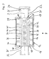
- the mixing device 8 has a housing 12, which in turn has a peripheral portion 14 and two opposite connection plates 16, 18 which laterally close the open ends of the peripheral portion 14.
- the connection plate 18 has centrally a circular inlet 20 for introducing flowable material into the interior of the housing 12.
- the inlet 20 communicates with a coaxially to a longitudinal axis 3 of the mixing device 8 arranged pipe socket 22, which has a protruding collar 24 at its free end.
- the pipe socket 22 can be connected to the filling tube 4 of the filling machine 1, so that flowable mass such as sausage meat from the filling machine 1 into the interior of the mixing device 8 and through the mixing device 8 is conveyed through.
- the connecting plate 18 engages over the peripheral portion 14 and is additionally sealed by means of a seal 28.
- screw connection plates 16, 18 are screwed to the peripheral portion 14.
- An outlet 30 for discharging the mass from inside the mixing device 8 is formed as a circular opening in the center of the terminal plate 16.
- a pipe socket 32 communicates with the outlet 30 and has a collar or external thread, so that the mixing device 8 by means of a union nut or by means of a thread with another device, such as the attachment 10, is connectable.
- the connection plate 16 is also sealed by means of an O-ring seal 34 relative to the peripheral portion 14 of the housing.
- two helical mixing elements 36, 38 for mixing and / or processing of mass are arranged side by side within the housing 12 of the mixing device 8.
- the longitudinal axes 37, 39 of the mixing elements 36, 38 are arranged parallel to one another and parallel to the longitudinal axis 3.
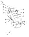
- Each mixing element 36, 38 has a substantially cylindrical core 40, 42 and in each case a helically extending winding 44, 46 projecting essentially radially from the core 40, 42.
- the turns 44, 46 of a helical mixing element 36, 38 extend continuously, continuously without interruption substantially over the entire axial length of the housing. However, this is not mandatory.
- the windings 44, 46 engage each other with their inner portions, in the exemplary embodiment so that the peripheral peripheral surface of a turn 44, 46 is almost or completely in contact with the core 40, 42 of the adjacent mixing element 36, 38. Further, the peripheral peripheral surface of a turn 44, 46 is in sections with the inner surface of the peripheral portion 14 of the housing 12 in contact.
- more than two, for example three, four or more helical mixing elements could be arranged within the housing 12, preferably parallel and adjacent to each other.
- the helical mixing elements 36, 38 are arranged so that free flow cross sections are formed between the cores 40, 42 and the housing sections, which are shaped such that mass introduced through the inlet 20 along these free flow cross sections, guided by the windings 44, 46, can flow through the interior of the mixing device 8, thereby deflected and mixed, and then to be discharged through the outlet 30 from the interior of the mixing device can.
- the pitch of a turn is about 48 mm.
- the thickness of a turn is in the range of 8 mm.
- Each mixing element has about 4.5 gears. However, these values should be adapted to the particular flowable food masses to be processed as required.
- the mixing elements 36, 38 are static in operation, that is, non-rotatably and stationarily positioned within the housing 12.
- substantially cylindrical recesses or depressions 48 are formed on the connection plates 16, 18 on the inner surface, in which the cylindrical end sections of the cores 40, 42 of the mixing elements 36, 38 are arranged.
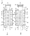
- a securing device against axial rotation serves the following purpose: At least one helical mixing element, in the exemplary embodiment, the mixing element 38 is rotatably disposed about a longitudinal axis 39 and by means of the securing device in operation in a plurality of rotational positions fixable.
- a bore 50 is formed in the turn 46 in the region of one of its ends, in which a cylindrical pin, not shown, can be inserted.
- two bores 52, 54 are formed in the connecting plate 18 of the housing 12, in which optionally depending on the rotational position of the rotatable mixing element 38 of the pin can be inserted, depending on whether the bore 50 is aligned with the bore 52 or 54.
- FIG. 4 shows two different rotational positions of the rotatable mixing element 38 in position 1 and position 2.
- the differences of position 1 to position 2 according to FIG. 4 show that the distances of the windings 44, 46 of the mixing elements 36, 38 are different depending on the rotational position of the two mixing elements 36, 38 relative to each other, as one very well in the inner region, where the windings 44, 46 interlock can recognize. How one FIG. 4 takes a narrow gap S 1 is realized in position 1, while an enlarged, wider gap S 2 in position 2 can be seen.
- the free flow cross sections for the flowable mass can be varied depending on the properties of the mass.
- the free flow cross sections depending on the viscosity of the mass or whether or not sensitive deposits such as mushrooms or the like are present in a sausage meat or other mass, it may be desirable to vary the free flow cross sections.
- This adaptation may be particularly desirable to achieve different mixing results.
Landscapes
- Life Sciences & Earth Sciences (AREA)
- Engineering & Computer Science (AREA)
- Chemical & Material Sciences (AREA)
- Wood Science & Technology (AREA)
- Zoology (AREA)
- Food Science & Technology (AREA)
- Dispersion Chemistry (AREA)
- Chemical Kinetics & Catalysis (AREA)
- Processing Of Meat And Fish (AREA)
- Meat, Egg Or Seafood Products (AREA)
Abstract
Description
Die vorliegende Erfindung betrifft eine Mischvorrichtung nach dem Oberbegriff des Anspruchs 1 und eine Füllmaschine nach dem Oberbegriff des Anspruchs 13.The present invention relates to a mixing device according to the preamble of
Füllmaschinen der eingangs genannten Art dienen zum Abfüllen pastöser Lebensmittel-massen in Verpackungen. So können mit Hilfe solcher Füllmaschinen Fleischprodukte wie Brühwurst, Hackfleisch, Würstchen oder dgl. in Hüllen aus Natur- oder Kunstdarm abgefüllt werden. Eine Füllmaschine weist einen Fülltrichter zur Aufnahme der Masse, eine Förderpumpe und ein Füll-Rohr zum Abgeben der Masse auf. Der Füllmaschine nachgeschaltet sein können beispielsweise Clipper zum Abklemmen von Enden eines Wurstabschnitts, Füllstromteiler zum Aufteilen des Massenstroms in mehrere einzelne Massenströme oder andere sog. Vorsatzgeräte, die mit einer Füllmaschine gekoppelt werden können. Eine Füllmaschine kann auch mit einer nachgeschalteten Mischvorrichtung der eingangs genannten Art gekoppelt werden.Filling machines of the type mentioned above are used for filling pasty food masses in packaging. So with the help of such filling machines meat products such as boiled sausage, minced meat, sausages or the like. Be bottled in natural or artificial casing. A filling machine has a hopper for receiving the mass, a feed pump and a filling tube for discharging the mass. The filling machine can be followed, for example, by clips for clamping ends of a sausage section, filling flow dividers for dividing the mass flow into a plurality of individual mass flows or other so-called attachment devices which can be coupled to a filling machine. A filling machine can also be coupled with a downstream mixing device of the type mentioned.
Mischvorrichtungen kommen beispielsweise bei der Abfüllung von Brühwurstmassen zum Einsatz. Bei der Abfüllung von Brühwurstmassen kann es zu einer Agglomeration von in der Masse vorhandener Luft, d. h. zu einer Bildung von größeren Luftblasen innerhalb der Masse, kommen, die unerwünscht sind und von Kunden nicht akzeptiert werden. Mithilfe einer der Füllmaschine nachgeschalteten Messvorrichtung wird in der Masse enthaltene Luft fein verteilt. Im Stand der Technik kommen unterschiedliche Arten von Mischvorrichtungen zum Einsatz.Mixing devices are used, for example, in the filling of scalded sausage masses. When filling scalding masses, agglomeration of air present in the mass, ie formation of larger air bubbles within the mass, can occur, which are undesirable and are not accepted by customers. With the aid of a measuring device connected downstream of the filling machine, air contained in the mass is finely distributed. The prior art uses different types of mixing devices.
So kommen innerhalb eines rohrförmigen Gehäuses angeordnete Düsen mit einer Querschnittsverengung zum Einsatz. Durchströmt die Luft enthaltende Brühwurst-Masse die Düse, kommt es etwa aufgrund von Turbulenzen zu einer Zerkleinerung großer Luftblasen. Je nach Produktart wird ein spezieller Düsendurchmesser verwendet. Der Ein- bzw. Umbau und der damit verbundene Aufwand wird als nachteilig angesehen. Ferner können in der Lebensmittel-Masse enthaltene Einlagen, beispielsweise Pilzstücke in Wurstbrät aufgrund der Querschnittsverengung beschädigt oder zerstört werden.Thus, arranged within a tubular housing nozzles with a cross-sectional constriction are used. If the scalding mass containing the air flows through the nozzle, comminution of large air bubbles occurs, for example due to turbulence. Depending on the product type, a special nozzle diameter is used. The installation or conversion and the associated effort is considered disadvantageous. Furthermore, deposits contained in the food mass, for example mushroom pieces in sausage meat, may be damaged or destroyed due to the cross-sectional constriction.
Des Weiteren kommen innerhalb des Gehäuses der Mischvorrichtung angeordnete Labyrinthdüsen zum Einsatz, die eine Vielzahl von labyrinthartigen Umlenkelementen aufweisen, die die Masse mehrfach umlenken und dadurch eine Luftverteilung bewirken. Auch hierbei kann es zur Beschädigungen von Einschlüssen, beispielswiese Pilzen kommen. Ferner können längere in der Masse vorhandene Fasern, wie Sehnen oder dergleichen, an den Umlenkelementen, insbesondere den Kanten der Umlenkelemente hängen bleiben und sich dort ansammeln, was zu einer Verstopfung der Labyrinthdüsen führen kann.Furthermore, arranged within the housing of the mixing device labyrinth nozzles are used, which have a plurality of labyrinth-like deflection elements, which redirect the mass several times and thereby cause an air distribution. Also here it can lead to the damage of inclusions, for example fungi. Furthermore, longer existing in the mass fibers, such as tendons or the like, to the deflecting elements, in particular the edges of the deflector hang and accumulate there, which can lead to clogging of the labyrinth nozzles.
Des Weiteren sind den Labyrinthdüsen ähnliche statische Mischer mit Trennelementen bekannt, die auch für eine Umlenkung der Strömung der Masse sorgen, aber auch den Nachteil aufweisen, dass Einlagen wie Pilze an den Trennflächen oder Kanten der Trennelemente beschädigt werden oder längliche Sehnen oder Fasern an den Kanten hängen bleiben und für Verstopfungen sorgen.Furthermore, similar to the labyrinth nozzles static mixers with separating elements are known, which also provide a diversion of the flow of the mass, but also have the disadvantage that deposits such as fungi are damaged at the parting surfaces or edges of the separating elements or elongated tendons or fibers at the edges get stuck and cause blockages.
Aufgabe der Erfindung ist es, eine Mischvorrichtung für fließfähige Lebensmittel-Massen, insbesondere Wurstbrät, Brühwurst oder andere Fleischprodukte bereitzustellen, bei denen es zu einer zuverlässigen, schonenden Durchmischung kommt. Insbesondere soll eine Mischvorrichtung bereitgestellt werden, mit der lufthaltige Brühwurst durchmischt oder Wurstbrät mit Einlagen schonend so durchmischt werden kann, dass auch empfindliche Einlagen wie Pilze nicht beschädigt werden. Ferner ist Aufgabe der Erfindung, eine Füllmaschine mit einer an diese gekoppelte Mischvorrichtung bereitzustellen.The object of the invention is to provide a mixing device for flowable food masses, in particular sausage meat, boiled sausage or other meat products, in which there is a reliable, gentle mixing. In particular, a mixing device should be provided, mixed with the air-containing scalded sausage or sausage meat with deposits can be gently mixed so that even sensitive deposits such as mushrooms are not damaged. It is another object of the invention to provide a filling machine with a mixing device coupled thereto.
Die Erfindung löst die Aufgabe mit einer Mischvorrichtung der eingangs genannten Art, bei der mindestens zwei innerhalb des Gehäuses statisch nebeneinander angeordnete schraubenförmige Mischelemente zum Mischen und/oder Bearbeiten von durch das Gehäuse fließender Masse vorhanden sind (Anspruch 1).The invention solves the problem with a mixing device of the type mentioned, in which there are at least two static mixing elements arranged adjacently within the housing for mixing and / or processing mass flowing through the housing (claim 1).
Die Erfindung löst die Aufgabe ferner mit einer Füllmaschine der eingangs genannten Art, die mit einer erfindungsgemäßen Mischvorrichtung gekoppelt ist (Anspruch 13).The invention further solves the problem with a filling machine of the type mentioned, which is coupled with a mixing device according to the invention (claim 13).
Durch die benachbarten schraubenförmigen Mischelemente wird die hindurch strömende Lebensmittel-Masse besonders schonend durchmischt. Zu diesem Zweck wird die Masse, insbesondere ein Wurstbrät, welches Einlagen enthalten kann, in das Gehäuse hinein gefördert und durchströmt dann die freien Strömungsquerschnitte zwischen den benachbart angeordneten schraubenförmigen Mischelementen. Die schraubenförmigen Mischelemente sind während des Betriebs grundsätzlich statisch angeordnet, d. h. sie drehen grundsätzlich nicht, sondern sind ortsfest fixiert innerhalb des Gehäuses. Aufgrund der schraubenförmigen Form der Windungen der Mischelemente kommt es zu vergleichsweise schonenden Umlenkungen der Strömung der Masse und zu Trennungen des Massenstroms entlang der schraubenförmigen freien Strömungsquerschnitte zur Durchmischung. Agglomerationen werden dadurch verringert und Gas feiner verteilt. Gleichzeitig werden auch empfindliche Einlagen in der Masse, wie Pilze, nicht beschädigt. Ansammlungen von längeren Partikeln wie Fasern oder Sehnen, werden gleichermaßen vermieden, da keine Kanten von Leitelementen vorhanden sind.By the adjacent helical mixing elements, the flowing through food mass is mixed very gently. For this purpose, the mass, in particular a sausage meat, which may contain deposits, conveyed into the housing and then flows through the free flow cross sections between the adjacent arranged helical mixing elements. The helical mixing elements are basically arranged statically during operation, d. H. they basically do not rotate, but are fixed in place within the housing. Due to the helical shape of the turns of the mixing elements, there are comparatively gentle deflections of the flow of the mass and separations of the mass flow along the helical free flow cross-sections for mixing. Agglomerations are thereby reduced and gas is dispersed more finely. At the same time, sensitive deposits in the mass, such as mushrooms, are not damaged. Accumulations of longer particles, such as fibers or tendons, are likewise avoided since no edges of guide elements are present.
Eine besonders effektive Durchmischung ergibt sich gemäß einer vorteilhaften Ausführungsform dadurch, dass die schraubenförmig verlaufenden Windungen zweier benachbarter Mischelemente ineinander greifen.A particularly effective mixing results according to an advantageous embodiment in that the helically extending turns of two adjacent mixing elements interlock.
Gemäß einer bevorzugten Ausführungsform wird vorgeschlagen, dass die Windung eines schraubenförmigen Mischelementes sich kontinuierlich ohne Unterbrechung im Wesentlichen über die gesamte axiale Länge des Gehäuses erstreckt. Dadurch ist sichergestellt, dass keine Kanten vorhanden sind, an denen sich Sehnen oder andere Partikel festsetzen könnten.According to a preferred embodiment, it is proposed that the turn of a helical mixing element extends continuously without interruption substantially over the entire axial length of the housing. This ensures that there are no edges at which tendons or other particles may seize.
Ferner wird vorgeschlagen, dass sich eine Windung in radialer Richtung im Wesentlichen bis zum Kern eines benachbarten Mischelementes erstreckt, und die Längsachsen der schraubenförmigen Mischelemente im Wesentlichen parallel zueinander angeordnet sind. Hierdurch ist eine definierte Strömung gewährleistet, die sich teilweise nach außen bis zur Gehäusewandung und dann wieder nach innen bewegt, um dort zu einer erneuten Vermischung von Teilströmungen zu führen.It is also proposed that a turn extends in the radial direction substantially to the core of an adjacent mixing element, and the longitudinal axes of the helical mixing elements are arranged substantially parallel to each other. In this way, a defined flow is ensured, which moves partly outwards to the housing wall and then back in, to lead there to a renewed mixing of partial flows.
Eine alternative Ausführungsform zeichnet sich dadurch aus, dass drei oder mehr schraubenförmige Mischelemente parallel und benachbart zueinander innerhalb des Gehäuses angeordnet sind. Hierdurch wird insbesondere erreicht, dass größere Mengen verarbeitet werden können und/oder eine höhere Durchmischung erzielt wird, ohne dass die Baulänge der Vorrichtung vergrößert würde.An alternative embodiment is characterized in that three or more helical mixing elements are arranged parallel and adjacent to each other within the housing. In this way, in particular, it is achieved that larger quantities can be processed and / or a higher mixing is achieved without the overall length of the device being increased.
Die Mischungsströmung wird ferner vorteilhaft dadurch weitergebildet, dass die Windungen der Mischelemente mit ihrer äußeren Umfangsfläche in Kontakt mit dem Gehäuse stehen.The mixing flow is further advantageously further developed in that the turns of the mixing elements are in contact with the housing with their outer peripheral surface.
Gemäß einer alternativen Ausführungsform wird vorgeschlagen, dass mindestens eines der schraubenförmigen Mischelemente innerhalb des Gehäuses um eine Längsachse drehbar angeordnet ist und im Betrieb in mehreren Drehstellungen fixierbar ist. Durch eine Verdrehung eines schraubenförmigen Mischelementes kann der Abstand zweier benachbarter Windungen variiert und eingestellt werden. Dies kann einer Anpassung an spezifische Produkteigenschaften dienen. Im Betrieb wird das Mischelement nach der Einstellung fixiert, so dass es während der Durchströmung nicht verdreht, also statisch ist. Die Fixierung erfolgt vorteilhafterweise dadurch, dass das drehbare schraubenförmige Mischelement mittels eines Stiftes fixierbar ist, welcher mit einem Ende innerhalb einer Bohrung in dem Gehäuse angeordnet ist und mit einem Ende mit einer Bohrung in einer Windung des schraubenförmigen Mischelementes in Eingriff bringbar ist.According to an alternative embodiment, it is proposed that at least one of the helical mixing elements is rotatably arranged within the housing about a longitudinal axis and in operation in a plurality of rotational positions can be fixed. By a rotation of a helical mixing element, the distance between two adjacent turns can be varied and adjusted. This can serve for adaptation to specific product properties. In operation, the mixing element is fixed after adjustment, so that it is not twisted during the flow, so it is static. The fixation is advantageously carried out in that the rotatable helical mixing element is fixable by means of a pin which is arranged with one end within a bore in the housing and with one end engageable with a bore in a turn of the helical mixing element.
Eine alternative Ausführungsform zeichnet sich dadurch aus, dass das Gehäuse einen Umfangsabschnitt und zwei gegenüberliegende Anschlussplatten aufweist, die den Einlass bzw. Auslass aufweisen und/oder dass das Gehäuse mittels eines an einer Anschlussplatte angeordneten Rohrstutzens und einer Überwurfmutter an einer Füllmaschine befestigbar ist und/oder dass das Gehäuse mittels eines an einer Anschlussplatte angeordneten Rohrstutzens mit einem Vorsatzgerät koppelbar ist. Auf diese Weise lassen sich einfache Anschlussmöglichkeiten realisieren.An alternative embodiment is characterized in that the housing has a peripheral portion and two opposite connection plates, which have the inlet or outlet and / or that the housing is fastened by means of a connection piece arranged on a pipe socket and a union nut on a filling machine and / or in that the housing can be coupled to a front attachment by means of a pipe socket arranged on a connection plate. In this way, simple connection options can be realized.
Eine alternative Ausführungsform sieht vor, dass die Steigung einer Windung im Bereich 12 bis 72 mm liegt und/oder dass die Dicke einer Windung im Bereich zwischen 4 und 20 mm und/oder dass jedes schraubenförmige Mischelement etwa 3 bis 10 Windungen aufweist.An alternative embodiment provides that the pitch of a turn is in the range of 12 to 72 mm and / or that the thickness of a turn is in the range of 4 to 20 mm and / or that each helical mixing element has about 3 to 10 turns.
Die obigen Vorteile werden gleichermaßen bei einer Kombination aus Füllmaschine und damit kooperierender, nachgeschalteter Mischvorrichtung erreicht (Anspruch 13). Es wird insoweit auf die obigen Beschreibungen Bezug genommen.The above advantages are equally achieved in a combination of filling machine and thus cooperating, downstream mixing device (claim 13). In this regard, reference is made to the above descriptions.
Die Erfindung ist nachstehend anhand eines Ausführungsbeispiels einer Füllmaschine und einer Mischvorrichtung näher erläutert, es zeigen:
Figur 1- eine Füllmaschine mit daran angeschlossener Mischvorrichtung in einer Seitenansicht;
Figur 2- eine erfindungsgemäße Mischvorrichtung in einer Schnittdarstellung;
Figur 3- ein Teil der erfindungsgemäßen Mischvorrichtung aus
Figur 2 Figur 4- die Mischvorrichtung in einer Schnittdarstellung in zwei
Positionen 1 und 2, mit unterschiedlich zueinander eingestellten Schrauben.
- FIG. 1
- a filling machine with attached mixing device in a side view;
- FIG. 2
- a mixing device according to the invention in a sectional view;
- FIG. 3
- a part of the mixing device according to the invention
FIG. 2 in a perspective view; and - FIG. 4
- the mixing device in a sectional view in two
positions
Die in
Eine Mischvorrichtung 8 zum Mischen und/oder Bearbeiten der fließfähigen Lebensmittel-Masse gemäß der Erfindung ist im Ausführungsbeispiel an die Füllmaschine 1 gekoppelt, sie könnte aber auch an eine andere Pumpe zum Fördern einer pastösen Lebensmittel-Masse gekoppelt sein oder mit einer Leitung, durch die pastöse Masse hindurch förderbar ist, verbunden sein. Die Mischvorrichtung 8, auch in den
In Flussrichtung der Masse ist der Mischvorrichtung 8 ein so genanntes Vorsatzgerät 10 nachgeschaltet, bei dem es sich im Ausführungsbeispiel um einen Portionierer handelt. Es könnte auch alternativ als Füllstromteiler, Wolf oder so genannten Clipper zum Abteilen und Verschließen einzelner Wurstportionen oder dergleichen ausgebildet sein.In the flow direction of the mass of the
Die Mischvorrichtung 8 weist ein Gehäuse 12 auf, welches seinerseits einen Umfangsabschnitt 14 und zwei gegenüberliegende Anschlussplatten 16, 18 aufweist, die die offenen Enden des Umfangsabschnitts 14 seitlich verschließen. Die Anschlussplatte 18 weist mittig einen kreisförmigen Einlass 20 zum Einleiten von fließfähiger Masse in das Innere des Gehäuses 12 auf. Der Einlass 20 kommuniziert mit einem koaxial zu einer Längsachse 3 der Mischvorrichtung 8 angeordneten Rohrstutzen 22, welcher an seinem freien Ende einen vorstehenden Bund 24 aufweist. Mittels einer den Bund 24 hintergreifenden Überwurfmutter 26, lässt sich der Rohrstutzen 22 an das Füllrohr 4 der Füllmaschine 1 anschließen, so dass fließfähige Masse wie Wurstbrät aus der Füllmaschine 1 in das Innere der Mischvorrichtung 8 hinein und durch die Mischvorrichtung 8 hindurch förderbar ist. Die Anschlussplatte 18 übergreift den Umfangsabschnitt 14 und ist mittels einer Dichtung 28 zusätzlich abgedichtet. Mittels Schraubverbindung sind die Anschlussplatten 16, 18 mit dem Umfangsabschnitt 14 verschraubt.The
Ein Auslass 30 zum Abgeben der Masse aus dem Inneren der Mischvorrichtung 8 ist als kreisförmige Öffnung mittig an der Anschlussplatte 16 ausgebildet. Ein Rohrstutzen 32 kommuniziert mit dem Auslass 30 und weist ein Bund oder Außengewinde auf, so dass die Mischvorrichtung 8 mittels einer Überwurfmutter oder mittels eines Gewindes mit einem weiteren Gerät, wie dem Vorsatzgerät 10, verbindbar ist. Die Anschlussplatte 16 ist ebenfalls mittels einer O-Ring-Dichtung 34 gegenüber dem Umfangsabschnitt 14 des Gehäuses abgedichtet.An
Wie die
In nicht gezeigter Weise könnten auch mehr als zwei, beispielsweise drei, vier oder mehr schraubenförmige Mischelemente innerhalb des Gehäuses 12 angeordnet sein, vorzugsweise parallel und benachbart zueinander.In a manner not shown, more than two, for example three, four or more helical mixing elements could be arranged within the
Die schraubenförmigen Mischelemente 36, 38 sind so angeordnet, dass freie Strömungsquerschnitte zwischen den Kernen 40, 42 und den Gehäuseabschnitten ausgebildet sind, die so geformt sind, dass durch den Einlass 20 eingeleitete Masse entlang dieser freien Strömungsquerschnitte, geleitet durch die Windungen 44, 46, durch das Innere der Mischvorrichtung 8 hindurch strömen kann, dabei umgelenkt und vermischt wird, um dann durch den Auslass 30 aus dem Inneren der Mischvorrichtung abgegeben werden zu können.The
Im Ausführungsbeispiel beträgt die Steigung einer Windung etwa 48 mm. Die Dicke einer Windung liegt im Bereich von 8 mm. Jedes Mischelement weist etwa 4,5 Gänge auf. Jedoch sind diese Werte an die jeweiligen zu verarbeitenden fließfähigen Lebensmittel-massen je nach Bedarf anzupassen.In the exemplary embodiment, the pitch of a turn is about 48 mm. The thickness of a turn is in the range of 8 mm. Each mixing element has about 4.5 gears. However, these values should be adapted to the particular flowable food masses to be processed as required.
Die Mischelemente 36, 38 sind im Betrieb statisch, dass heißt unverdrehbar und ortsfest innerhalb des Gehäuses 12 positioniert. Hierzu sind an den Anschlussplatten 16, 18 an der Inneren Oberfläche im Wesentlichen zylindrische Ausnehmungen oder Vertiefungen 48 ausgebildet, in denen die zylindrischen Endabschnitte der Kerne 40, 42 der Mischelemente 36, 38 angeordnet sind. Eine zusätzliche lösbare Sicherung gegen ein Verdrehen ist durch unten näher beschriebene Stifte und Bohrungen näher realisiert.The mixing
Die perspektivische Darstellung gemäß
Die
Dadurch lassen sich die freien Strömungsquerschnitte für die fließfähige Masse je nach Eigenschaften der Masse variieren. So kann es beispielsweise in Abhängigkeit von der Viskosität der Masse oder davon, ob empfindliche Einlagen wie Pilze oder dergleichen in einem Wurstbrät oder einer anderen Masse vorhanden sind oder nicht, wünschenswert sein, die freien Strömungsquerschnitte zu variieren. Diese Anpassung kann insbesondere wünschenswert sein, um unterschiedliche Mischergebnisse zu erreichen. Beispielsweise kann es wünschenswert sein, die freien Strömungsquerschnitte in ihrer Größe variieren zu können, um Gaseinschlüsse, wie Luftblasen oder dergleichen besonders gut fein verteilen zu können oder die Einlagen während der Durchströmung zu schonen.As a result, the free flow cross sections for the flowable mass can be varied depending on the properties of the mass. Thus, for example, depending on the viscosity of the mass or whether or not sensitive deposits such as mushrooms or the like are present in a sausage meat or other mass, it may be desirable to vary the free flow cross sections. This adaptation may be particularly desirable to achieve different mixing results. For example, it may be desirable to be able to vary the size of the free flow cross sections in order to be able to disperse gas inclusions, such as air bubbles or the like, particularly well or to protect the inserts during the throughflow.
Statt einer Einstellung und Fixierung mithilfe der Bohrungen 50, 52, 54 und einem Stift wären auch andere Dreh- und Sicherungsmechanismen möglich. So könnte beispielsweise zur Verdrehung eines der Mischelemente 36, 38 ein motorischer Antrieb realisiert sein.Instead of adjustment and fixation using the
Claims (14)
gekennzeichnet durch mindestens zwei innerhalb des Gehäuses statisch nebeneinander angeordnete schraubenförmige Mischelemente (36, 38) zum Mischen und/oder Bearbeiten von durch das Gehäuse fließender Masse.Mixing device for flowable food masses, in particular sausage meat, with a housing (12) having an inlet (20) for introducing the mass and an outlet (30) for discharging the mass,
characterized by at least two helical mixing elements (36, 38) arranged statically next to one another inside the housing for mixing and / or processing mass flowing through the housing.
dadurch gekennzeichnet dass die schraubenförmig verlaufenden Windungen (44, 46) zweier benachbarter Mischelemente (36, 38) ineinander greifen.Mixing device according to claim 1,
characterized in that the helically extending turns (44, 46) of two adjacent mixing elements (36, 38) engage with each other.
dadurch gekennzeichnet, dass die Windung (44, 46) eines schraubenförmigen Mischelementes (36, 38) sich kontinuierlich ohne Unterbrechung im Wesentlichen über die gesamte axiale Länge des Gehäuses (12) erstreckt.Mixing device according to claim 1 or 2,
characterized in that the turn (44, 46) of a helical mixing element (36, 38) extends continuously without interruption substantially over the entire axial length of the housing (12).
dadurch gekennzeichnet, dass sich eine Windung (44, 46) in radialer Richtung im Wesentlichen bis zum Kern (40, 42) eines benachbarten Mischelementes (36, 38) erstreckt und
die Längsachsen (37, 39) der schraubenförmigen Mischelemente (36, 38) im Wesentlichen parallel zueinander angeordnet sind.Mixing device according to claim 1, 2 or 3,
characterized in that a turn (44, 46) extends in the radial direction substantially to the core (40, 42) of an adjacent mixing element (36, 38) and
the longitudinal axes (37, 39) of the helical mixing elements (36, 38) are arranged substantially parallel to one another.
dadurch gekennzeichnet, dass drei oder mehr schraubenförmige Mischelemente parallel und benachbart zueinander innerhalb des Gehäuses (12) angeordnet sind.Mixing device according to one of the preceding claims,
characterized in that three or more helical mixing elements are arranged parallel and adjacent to each other within the housing (12).
dadurch gekennzeichnet, dass die Windungen (44, 46) der Mischelemente (36, 38) mit ihrer äußeren Umfangsfläche in Kontakt mit dem Gehäuse (12) stehen.Mixing device according to one of the preceding claims,
characterized in that the turns (44, 46) of the mixing elements (36, 38) with their outer peripheral surface in contact with the housing (12).
dadurch gekennzeichnet, dass mindestens eines der schraubenförmigen Mischelemente (36, 38) innerhalb des Gehäuses (12) um eine Längsachse (37, 39) drehbar angeordnet ist und im Betrieb in mehreren Drehstellungen fixierbar ist.Mixing device according to one of the preceding claims,
characterized in that at least one of the helical mixing elements (36, 38) within the housing (12) about a longitudinal axis (37, 39) is rotatably mounted and in operation in a plurality of rotational positions can be fixed.
dadurch gekennzeichnet, dass das drehbare schraubenförmige Mischelement (38) mittels eines Stiftes fixierbar ist, welcher mit einem ersten Ende innerhalb einer Bohrung (52, 54) in dem Gehäuse (12) angeordnet ist und mit einem zweiten Ende mit einer Bohrung (50) in einer Windung (46) des schraubenförmigen Mischelementes (38) in Eingriff bringbar ist.Mixing device according to claim 7,
characterized in that the rotatable helical mixing element (38) is fixable by means of a pin disposed with a first end within a bore (52, 54) in the housing (12) and with a second end having a bore (50) in a turn (46) of the helical mixing element (38) is engageable.
dadurch gekennzeichnet, dass das Gehäuse (12) einen Umfangsabschnitt (14) und zwei gegenüberliegende Anschlussplatten (16, 18) aufweist, die den Einlass (20) bzw. Auslass (30) aufweisen.Mixing device according to one of the preceding claims,
characterized in that the housing (12) has a peripheral portion (14) and two opposing terminal plates (16, 18) having the inlet (20) and outlet (30), respectively.
dadurch gekennzeichnet, dass das Gehäuse (12) mittels eines an einer Anschlussplatte (18) angeordneten Rohrstutzens (22) und einer Überwurfmutter (26) an einer Füllmaschine (1) befestigbar ist.Mixing device according to claim 9,
characterized in that the housing (12) by means of a pipe to a connection plate (18) arranged pipe socket (22) and a union nut (26) on a filling machine (1) can be fastened.
dadurch gekennzeichnet, dass das Gehäuse (12) mittels eines an einer Anschlussplatte (16) angeordneten Rohrstutzens (32) mit einem Vorsatzgerät (10) koppelbar istMixing device according to claim 9 or 10,
characterized in that the housing (12) by means of a pipe to a connection plate (16) arranged pipe socket (32) with a header (10) is coupled
dadurch gekennzeichnet, dass die Steigung einer Windung (44, 46) im Bereich von 12 bis 72 mm liegt und/oder dass die Dicke einer Windung (44, 46) im Bereich zwischen 4 und 20 mm und/oder dass jedes schraubenförmige Mischelement (36, 38) etwa 3 bis 10 Windungen (44, 46) aufweist.Mixing device according to one of the preceding claims,
characterized in that the pitch of a turn (44, 46) is in the range of 12 to 72 mm and / or that the thickness of a turn (44, 46) is in the range of 4 to 20 mm and / or in that each helical mixing element (36 , 38) has about 3 to 10 turns (44, 46).
gekennzeichnet durch eine mit dem Füllrohr (4) kommunizierende Mischvorrichtung (8) mit einem Gehäuse, welches einen Einlass zum Einleiten der Masse und einen Auslass (30) zum Abgeben der Masse aufweist,
und durch mindestens zwei innerhalb des Gehäuses statisch nebeneinander angeordnete schraubenförmige Mischelemente zum Mischen und/oder Bearbeiten von durch das Gehäuse fließender Masse.Filling machine for conveying and / or filling flowable food masses, in particular sausage meat, with a preferably funnel-shaped storage container (2) for receiving the mass, a filling pump for conveying the mass and a filling pipe communicating with the filling pump (4) for dispensing the mass to be filled,
characterized by a mixing device (8) communicating with the filling pipe (4), comprising a housing having an inlet for introducing the mass and an outlet (30) for discharging the mass,
and by at least two helical mixing elements arranged statically next to one another within the housing for mixing and / or processing mass flowing through the housing.
dadurch gekennzeichnet, dass die Mischvorrichtung (8) nach mindestens einem der vorstehenden Ansprüche ausgebildet ist.Filling machine according to claim 13,
characterized in that the mixing device (8) is designed according to at least one of the preceding claims.
Applications Claiming Priority (1)
| Application Number | Priority Date | Filing Date | Title |
|---|---|---|---|
| DE202009002115U DE202009002115U1 (en) | 2009-02-13 | 2009-02-13 | Mixing device for food masses such as sausage meat and filling machine |
Publications (3)
| Publication Number | Publication Date |
|---|---|
| EP2218331A2 true EP2218331A2 (en) | 2010-08-18 |
| EP2218331A3 EP2218331A3 (en) | 2012-03-14 |
| EP2218331B1 EP2218331B1 (en) | 2018-04-18 |
Family
ID=42132198
Family Applications (1)
| Application Number | Title | Priority Date | Filing Date |
|---|---|---|---|
| EP10153426.1A Not-in-force EP2218331B1 (en) | 2009-02-13 | 2010-02-12 | Mixing device for food-masses such as sausage meat and filling machine |
Country Status (4)
| Country | Link |
|---|---|
| US (1) | US8757867B2 (en) |
| EP (1) | EP2218331B1 (en) |
| DE (1) | DE202009002115U1 (en) |
| RU (1) | RU2448466C2 (en) |
Cited By (3)
| Publication number | Priority date | Publication date | Assignee | Title |
|---|---|---|---|---|
| EP2468106A1 (en) * | 2010-12-22 | 2012-06-27 | Albert Handtmann Maschinenfabrik GmbH & Co. KG | Device and method for distributing residual air in paste masses, in particular for producing sausages |
| DE202018105163U1 (en) | 2018-09-10 | 2018-09-18 | Albert Handtmann Maschinenfabrik Gmbh & Co. Kg | Device for the fine distribution of air fractions in pasty masses |
| EP3785542A1 (en) * | 2019-08-30 | 2021-03-03 | Herbert Ospelt Anstalt | Method for manufacturing a layered food product und production line for processing a meat product |
Families Citing this family (8)
| Publication number | Priority date | Publication date | Assignee | Title |
|---|---|---|---|---|
| DE202009002115U1 (en) * | 2009-02-13 | 2010-07-15 | Vemag Maschinenbau Gmbh | Mixing device for food masses such as sausage meat and filling machine |
| DE102012216912B4 (en) * | 2012-09-20 | 2018-07-26 | Vemag Maschinenbau Gmbh | Food conveying device, and method for conveying a food |
| CN103908944A (en) * | 2012-12-30 | 2014-07-09 | 灯塔北方化工有限公司 | High-pressure alcoholysis device |
| CA2934000A1 (en) | 2013-12-20 | 2015-06-25 | Gaia Usa, Inc. | Apparatus and method for liquids and gases |
| EP3609346B1 (en) | 2017-04-12 | 2023-08-02 | Gaia USA Inc. | Apparatus and method for generating and mixing ultrafine gas bubbles into a high gas concentration aqueous solution |
| CN107212056B (en) * | 2017-06-23 | 2018-08-28 | 杨茂燕 | A kind of food processing equipment |
| CA3120242A1 (en) | 2018-06-01 | 2019-12-05 | Gaia Usa, Inc. | Apparatus in the form of a unitary, single-piece structure configured to generate and mix ultra-fine gas bubbles into a high gas concentration aqueous solution |
| DE102024118429A1 (en) * | 2024-06-28 | 2025-12-31 | Albert Handtmann Maschinenfabrik Gmbh & Co.Kg | Filling machine and method for filling granular food products |
Family Cites Families (44)
| Publication number | Priority date | Publication date | Assignee | Title |
|---|---|---|---|---|
| DE294374C (en) | ||||
| US1698314A (en) * | 1923-11-09 | 1929-01-08 | Bailey Meter Co | Flow meter |
| US1972151A (en) * | 1932-02-26 | 1934-09-04 | Crane Co | Controlled flow plug valve |
| US2076465A (en) * | 1935-11-13 | 1937-04-06 | Kirk Corp | Flow bean |
| US2111463A (en) * | 1936-06-15 | 1938-03-15 | Dakota Theodore Smith | Mechanical force feeder for food choppers and grinders |
| US2836199A (en) * | 1955-05-09 | 1958-05-27 | United States Steel Corp | Orifice plate mounting |
| US3223388A (en) * | 1963-05-20 | 1965-12-14 | Du Pont | Apparatus for mixing |
| FR1422912A (en) * | 1964-10-13 | 1966-01-03 | Haut Rhin Manufacture Machines | Improvements in manufacturing techniques for sausages and similar products |
| US3474818A (en) * | 1966-05-02 | 1969-10-28 | Ralph E Hartman | Combined plug and check valve |
| US3484078A (en) * | 1966-07-01 | 1969-12-16 | Norman H Haenky | Valve |
| DE1900567A1 (en) | 1969-01-07 | 1970-08-13 | Vemag Verdener Masch App | Sausage meat blender screw feeder |
| GB1362205A (en) * | 1971-01-26 | 1974-07-30 | Alenco Ind Components Ltd | Pipe coupling |
| BE788921A (en) * | 1971-09-17 | 1973-01-02 | Apv Co Ltd | IMPROVEMENTS RELATED TO TURBULENCE GENERATING DEVICES |
| US3794300A (en) * | 1971-12-30 | 1974-02-26 | Dow Badische Co | Annular spiral isg |
| US3953002A (en) * | 1973-09-21 | 1976-04-27 | England Jr Herbert C | Motionless mixing device |
| US3949970A (en) * | 1974-01-02 | 1976-04-13 | Gebrs. ter Braak B.V. | Mixer |
| LU69549A1 (en) * | 1974-03-04 | 1976-02-04 | ||
| US4050676A (en) * | 1974-04-19 | 1977-09-27 | Yasushi Morishima | Mixing device and element therefor |
| FR2280420A1 (en) * | 1974-08-02 | 1976-02-27 | Siemens Ag | STATIC MIXER FOR FLOWING FLUIDS |
| US4284105A (en) * | 1979-11-09 | 1981-08-18 | Union Carbide Corporation | Discrete spiral flow imparting device |
| CA1145192A (en) * | 1980-02-06 | 1983-04-26 | General Foods, Inc. | Soft-moist pet food and process |
| US4524081A (en) * | 1983-11-08 | 1985-06-18 | The Quaker Oats Company | Method for making a marbled pet food |
| DE3539426A1 (en) * | 1985-11-07 | 1987-05-14 | Detec Kunststofftechnik Gmbh | Static mixing appliance for low- and high-viscosity substances |
| AU5676590A (en) | 1989-08-07 | 1991-03-11 | John G. Graves | Combination valve |
| US5004005A (en) * | 1989-08-07 | 1991-04-02 | Graves John G | Combination valve |
| US4989631A (en) * | 1990-05-14 | 1991-02-05 | Harbin Roy W | Valve device with control sleeve and check valve |
| RU2019967C1 (en) | 1990-08-13 | 1994-09-30 | Артур Германович Бауман | Device for filling sausage casings |
| US5881996A (en) * | 1995-08-28 | 1999-03-16 | Stockham Valves & Fittings, Inc. | Valve plug |
| EP1015735B1 (en) | 1997-02-07 | 2001-10-04 | J.S. Maskinfabrik A/S | Screw conveyor for the transport of liquid substances and/or lumps of materials |
| US5937906A (en) * | 1997-05-06 | 1999-08-17 | Kozyuk; Oleg V. | Method and apparatus for conducting sonochemical reactions and processes using hydrodynamic cavitation |
| DE29718684U1 (en) * | 1997-10-22 | 1999-02-25 | Vemag Maschinen- Und Anlagenbau Gmbh, 27283 Verden | Casing filling device and machine for filling sausage casings |
| US6102561A (en) * | 1998-01-05 | 2000-08-15 | Komax Systems, Inc. | Device for enhancing heat transfer and uniformity of a fluid stream with layers of helical vanes |
| US6016742A (en) * | 1998-12-18 | 2000-01-25 | Wenger Manufacturing, Inc. | Short length tapered extrusion cooking apparatus having peripheral die |
| FR2793146B1 (en) | 1999-05-07 | 2001-07-27 | Ela Medical Sa | ACTIVE IMPLANTABLE MEDICAL DEVICE, IN PARTICULAR A CARDIAC STIMULATOR, DEFIBRILLATOR AND / OR DDD / AAI-TYPE CARDIOVERTER WITH OPTIMIZED EFFORT OPERATION |
| US20020075754A1 (en) * | 2000-12-19 | 2002-06-20 | Wenger Manufacturing, Inc. | System for homogeneously mixing plural incoming product streams of different composition |
| DE10111001A1 (en) | 2001-03-07 | 2002-09-26 | Richard Meyenschein | Meat mincing machine comprises threads having sides that do not exactly fit together |
| US20040099145A1 (en) * | 2002-11-26 | 2004-05-27 | Good Humor-Breyers Ice Cream | Orifice modifier |
| US7188578B2 (en) * | 2005-03-29 | 2007-03-13 | Derosa Robert James | Cover plate removal tool |
| DE102005059052B4 (en) | 2005-12-08 | 2009-12-03 | Vemag Maschinenbau Gmbh | Vacuum filling machine with vacuum control |
| ES2314767T3 (en) | 2006-03-09 | 2009-03-16 | ALBERT HANDTMANN MASCHINENFABRIK GMBH & CO. KG | DEVICE FOR REGULATING THE FILLING LEVEL AND FOR EVACUATING REGULATED MASS PASTOSA. |
| DE202008004552U1 (en) * | 2008-04-03 | 2008-07-03 | Potthoff, Rüdiger | Device for mixing and dispensing plastic compounds |
| TW201008749A (en) * | 2008-06-25 | 2010-03-01 | Sulzer Chemtech Ag | An apparatus and method for the introduction of a foaming agent |
| DE202009002115U1 (en) * | 2009-02-13 | 2010-07-15 | Vemag Maschinenbau Gmbh | Mixing device for food masses such as sausage meat and filling machine |
| US8764731B2 (en) * | 2009-10-02 | 2014-07-01 | Medline Industries, Inc. | Connector for fluid conduit with integrated luer access port |
-
2009
- 2009-02-13 DE DE202009002115U patent/DE202009002115U1/en not_active Expired - Lifetime
-
2010
- 2010-02-12 US US12/704,922 patent/US8757867B2/en not_active Expired - Fee Related
- 2010-02-12 EP EP10153426.1A patent/EP2218331B1/en not_active Not-in-force
- 2010-02-12 RU RU2010105084/10A patent/RU2448466C2/en active
Non-Patent Citations (1)
| Title |
|---|
| None |
Cited By (5)
| Publication number | Priority date | Publication date | Assignee | Title |
|---|---|---|---|---|
| EP2468106A1 (en) * | 2010-12-22 | 2012-06-27 | Albert Handtmann Maschinenfabrik GmbH & Co. KG | Device and method for distributing residual air in paste masses, in particular for producing sausages |
| US9433222B2 (en) | 2010-12-22 | 2016-09-06 | Albert Handtmann Maschinenfabrik Gmbh & Co. Kg | Device and method for distributing residual air in pasty masses, in particular for the production of sausages |
| DE202018105163U1 (en) | 2018-09-10 | 2018-09-18 | Albert Handtmann Maschinenfabrik Gmbh & Co. Kg | Device for the fine distribution of air fractions in pasty masses |
| EP3785542A1 (en) * | 2019-08-30 | 2021-03-03 | Herbert Ospelt Anstalt | Method for manufacturing a layered food product und production line for processing a meat product |
| EP3788879A1 (en) * | 2019-08-30 | 2021-03-10 | Herbert Ospelt Anstalt | Production line for the improvementof a meat product |
Also Published As
| Publication number | Publication date |
|---|---|
| EP2218331B1 (en) | 2018-04-18 |
| RU2448466C2 (en) | 2012-04-27 |
| US20100208547A1 (en) | 2010-08-19 |
| RU2010105084A (en) | 2011-08-20 |
| EP2218331A3 (en) | 2012-03-14 |
| DE202009002115U1 (en) | 2010-07-15 |
| US8757867B2 (en) | 2014-06-24 |
Similar Documents
| Publication | Publication Date | Title |
|---|---|---|
| EP2218331B1 (en) | Mixing device for food-masses such as sausage meat and filling machine | |
| EP1931950B1 (en) | Dosing device for powerdy or pasty substances | |
| EP2755769B1 (en) | Device for mixing | |
| DE1751351A1 (en) | Device for combining streams of flowable food | |
| DE202016103908U1 (en) | metering | |
| DE102019102183A1 (en) | Solids feed device and mixing arrangement | |
| DE10342820B4 (en) | Device for forming three-layered foods | |
| EP1048213B1 (en) | Device for stuffing sausage meat | |
| EP1931952B1 (en) | Dosing device for powdery or pasty substances | |
| DE19537303B4 (en) | Device for homogenizing flowable substances | |
| EP1582467B1 (en) | Apparatus for the dosed filling of bulk material. | |
| EP2198717A2 (en) | Device for filling or processing paste masses, in particular sausage meat | |
| DE202004002601U1 (en) | Device for dosing bulk goods with an agitator and a drive unit | |
| EP0760254B1 (en) | Device for homogenising flowable materials | |
| DE202011005472U1 (en) | Device for extruding food masses | |
| DE4237010A1 (en) | Mixing valve and delivery device esp. for prepn. of drinks - has restricting plate dividing water flow into mixing chamber into number of streams, so water mixes intimately with drink concentrate | |
| DE102009013080A1 (en) | Method for packaging portioned pasty product i.e. emulsion, involves portioning product in pasty condition, and homogenizing directly product in pasty condition before transferring product into packaging and after portioning product | |
| EP2885088B1 (en) | Discharge device | |
| DE102008013806B4 (en) | Portioning device (cutting upwards) | |
| DE19514384C2 (en) | Mixing or dispersing device with a guide housing | |
| DE3406648A1 (en) | Mixing machine for continuous mixing processes | |
| DE10161180B4 (en) | Mixing device for mixing at least two liquid components | |
| EP2524725A1 (en) | Device for removing screenings from a liquid | |
| DE29716406U1 (en) | Device for conveying and processing sausage mass | |
| DE4228411C2 (en) | Device for squeezing paste-like masses in portions |
Legal Events
| Date | Code | Title | Description |
|---|---|---|---|
| PUAI | Public reference made under article 153(3) epc to a published international application that has entered the european phase |
Free format text: ORIGINAL CODE: 0009012 |
|
| AK | Designated contracting states |
Kind code of ref document: A2 Designated state(s): AT BE BG CH CY CZ DE DK EE ES FI FR GB GR HR HU IE IS IT LI LT LU LV MC MK MT NL NO PL PT RO SE SI SK SM TR |
|
| AX | Request for extension of the european patent |
Extension state: AL BA RS |
|
| PUAL | Search report despatched |
Free format text: ORIGINAL CODE: 0009013 |
|
| AK | Designated contracting states |
Kind code of ref document: A3 Designated state(s): AT BE BG CH CY CZ DE DK EE ES FI FR GB GR HR HU IE IS IT LI LT LU LV MC MK MT NL NO PL PT RO SE SI SK SM TR |
|
| AX | Request for extension of the european patent |
Extension state: AL BA RS |
|
| RIC1 | Information provided on ipc code assigned before grant |
Ipc: B01F 5/06 20060101ALI20120208BHEP Ipc: B01F 7/00 20060101ALI20120208BHEP Ipc: A22C 11/08 20060101ALI20120208BHEP Ipc: A22C 5/00 20060101AFI20120208BHEP |
|
| 17P | Request for examination filed |
Effective date: 20120914 |
|
| 17Q | First examination report despatched |
Effective date: 20140922 |
|
| GRAP | Despatch of communication of intention to grant a patent |
Free format text: ORIGINAL CODE: EPIDOSNIGR1 |
|
| STAA | Information on the status of an ep patent application or granted ep patent |
Free format text: STATUS: GRANT OF PATENT IS INTENDED |
|
| INTG | Intention to grant announced |
Effective date: 20171107 |
|
| GRAS | Grant fee paid |
Free format text: ORIGINAL CODE: EPIDOSNIGR3 |
|
| GRAA | (expected) grant |
Free format text: ORIGINAL CODE: 0009210 |
|
| STAA | Information on the status of an ep patent application or granted ep patent |
Free format text: STATUS: THE PATENT HAS BEEN GRANTED |
|
| AK | Designated contracting states |
Kind code of ref document: B1 Designated state(s): AT BE BG CH CY CZ DE DK EE ES FI FR GB GR HR HU IE IS IT LI LT LU LV MC MK MT NL NO PL PT RO SE SI SK SM TR |
|
| REG | Reference to a national code |
Ref country code: GB Ref legal event code: FG4D Free format text: NOT ENGLISH |
|
| RIN1 | Information on inventor provided before grant (corrected) |
Inventor name: NILSSON, KERSTEN Inventor name: KIEL, TOBIAS |
|
| REG | Reference to a national code |
Ref country code: CH Ref legal event code: EP |
|
| REG | Reference to a national code |
Ref country code: AT Ref legal event code: REF Ref document number: 989424 Country of ref document: AT Kind code of ref document: T Effective date: 20180515 |
|
| REG | Reference to a national code |
Ref country code: IE Ref legal event code: FG4D Free format text: LANGUAGE OF EP DOCUMENT: GERMAN |
|
| REG | Reference to a national code |
Ref country code: DE Ref legal event code: R096 Ref document number: 502010014867 Country of ref document: DE |
|
| REG | Reference to a national code |
Ref country code: NL Ref legal event code: FP |
|
| REG | Reference to a national code |
Ref country code: LT Ref legal event code: MG4D |
|
| PG25 | Lapsed in a contracting state [announced via postgrant information from national office to epo] |
Ref country code: ES Free format text: LAPSE BECAUSE OF FAILURE TO SUBMIT A TRANSLATION OF THE DESCRIPTION OR TO PAY THE FEE WITHIN THE PRESCRIBED TIME-LIMIT Effective date: 20180418 Ref country code: LT Free format text: LAPSE BECAUSE OF FAILURE TO SUBMIT A TRANSLATION OF THE DESCRIPTION OR TO PAY THE FEE WITHIN THE PRESCRIBED TIME-LIMIT Effective date: 20180418 Ref country code: PL Free format text: LAPSE BECAUSE OF FAILURE TO SUBMIT A TRANSLATION OF THE DESCRIPTION OR TO PAY THE FEE WITHIN THE PRESCRIBED TIME-LIMIT Effective date: 20180418 Ref country code: BG Free format text: LAPSE BECAUSE OF FAILURE TO SUBMIT A TRANSLATION OF THE DESCRIPTION OR TO PAY THE FEE WITHIN THE PRESCRIBED TIME-LIMIT Effective date: 20180718 Ref country code: NO Free format text: LAPSE BECAUSE OF FAILURE TO SUBMIT A TRANSLATION OF THE DESCRIPTION OR TO PAY THE FEE WITHIN THE PRESCRIBED TIME-LIMIT Effective date: 20180718 Ref country code: SE Free format text: LAPSE BECAUSE OF FAILURE TO SUBMIT A TRANSLATION OF THE DESCRIPTION OR TO PAY THE FEE WITHIN THE PRESCRIBED TIME-LIMIT Effective date: 20180418 Ref country code: FI Free format text: LAPSE BECAUSE OF FAILURE TO SUBMIT A TRANSLATION OF THE DESCRIPTION OR TO PAY THE FEE WITHIN THE PRESCRIBED TIME-LIMIT Effective date: 20180418 |
|
| PG25 | Lapsed in a contracting state [announced via postgrant information from national office to epo] |
Ref country code: GR Free format text: LAPSE BECAUSE OF FAILURE TO SUBMIT A TRANSLATION OF THE DESCRIPTION OR TO PAY THE FEE WITHIN THE PRESCRIBED TIME-LIMIT Effective date: 20180719 Ref country code: HR Free format text: LAPSE BECAUSE OF FAILURE TO SUBMIT A TRANSLATION OF THE DESCRIPTION OR TO PAY THE FEE WITHIN THE PRESCRIBED TIME-LIMIT Effective date: 20180418 Ref country code: LV Free format text: LAPSE BECAUSE OF FAILURE TO SUBMIT A TRANSLATION OF THE DESCRIPTION OR TO PAY THE FEE WITHIN THE PRESCRIBED TIME-LIMIT Effective date: 20180418 |
|
| PG25 | Lapsed in a contracting state [announced via postgrant information from national office to epo] |
Ref country code: PT Free format text: LAPSE BECAUSE OF FAILURE TO SUBMIT A TRANSLATION OF THE DESCRIPTION OR TO PAY THE FEE WITHIN THE PRESCRIBED TIME-LIMIT Effective date: 20180820 |
|
| REG | Reference to a national code |
Ref country code: DE Ref legal event code: R097 Ref document number: 502010014867 Country of ref document: DE |
|
| PG25 | Lapsed in a contracting state [announced via postgrant information from national office to epo] |
Ref country code: DK Free format text: LAPSE BECAUSE OF FAILURE TO SUBMIT A TRANSLATION OF THE DESCRIPTION OR TO PAY THE FEE WITHIN THE PRESCRIBED TIME-LIMIT Effective date: 20180418 Ref country code: EE Free format text: LAPSE BECAUSE OF FAILURE TO SUBMIT A TRANSLATION OF THE DESCRIPTION OR TO PAY THE FEE WITHIN THE PRESCRIBED TIME-LIMIT Effective date: 20180418 Ref country code: CZ Free format text: LAPSE BECAUSE OF FAILURE TO SUBMIT A TRANSLATION OF THE DESCRIPTION OR TO PAY THE FEE WITHIN THE PRESCRIBED TIME-LIMIT Effective date: 20180418 Ref country code: SK Free format text: LAPSE BECAUSE OF FAILURE TO SUBMIT A TRANSLATION OF THE DESCRIPTION OR TO PAY THE FEE WITHIN THE PRESCRIBED TIME-LIMIT Effective date: 20180418 Ref country code: RO Free format text: LAPSE BECAUSE OF FAILURE TO SUBMIT A TRANSLATION OF THE DESCRIPTION OR TO PAY THE FEE WITHIN THE PRESCRIBED TIME-LIMIT Effective date: 20180418 |
|
| PLBE | No opposition filed within time limit |
Free format text: ORIGINAL CODE: 0009261 |
|
| STAA | Information on the status of an ep patent application or granted ep patent |
Free format text: STATUS: NO OPPOSITION FILED WITHIN TIME LIMIT |
|
| PG25 | Lapsed in a contracting state [announced via postgrant information from national office to epo] |
Ref country code: SM Free format text: LAPSE BECAUSE OF FAILURE TO SUBMIT A TRANSLATION OF THE DESCRIPTION OR TO PAY THE FEE WITHIN THE PRESCRIBED TIME-LIMIT Effective date: 20180418 Ref country code: IT Free format text: LAPSE BECAUSE OF FAILURE TO SUBMIT A TRANSLATION OF THE DESCRIPTION OR TO PAY THE FEE WITHIN THE PRESCRIBED TIME-LIMIT Effective date: 20180418 |
|
| 26N | No opposition filed |
Effective date: 20190121 |
|
| PG25 | Lapsed in a contracting state [announced via postgrant information from national office to epo] |
Ref country code: SI Free format text: LAPSE BECAUSE OF FAILURE TO SUBMIT A TRANSLATION OF THE DESCRIPTION OR TO PAY THE FEE WITHIN THE PRESCRIBED TIME-LIMIT Effective date: 20180418 |
|
| REG | Reference to a national code |
Ref country code: CH Ref legal event code: PL |
|
| GBPC | Gb: european patent ceased through non-payment of renewal fee |
Effective date: 20190212 |
|
| PG25 | Lapsed in a contracting state [announced via postgrant information from national office to epo] |
Ref country code: MC Free format text: LAPSE BECAUSE OF FAILURE TO SUBMIT A TRANSLATION OF THE DESCRIPTION OR TO PAY THE FEE WITHIN THE PRESCRIBED TIME-LIMIT Effective date: 20180418 Ref country code: LU Free format text: LAPSE BECAUSE OF NON-PAYMENT OF DUE FEES Effective date: 20190212 |
|
| REG | Reference to a national code |
Ref country code: BE Ref legal event code: MM Effective date: 20190228 |
|
| REG | Reference to a national code |
Ref country code: IE Ref legal event code: MM4A |
|
| PG25 | Lapsed in a contracting state [announced via postgrant information from national office to epo] |
Ref country code: CH Free format text: LAPSE BECAUSE OF NON-PAYMENT OF DUE FEES Effective date: 20190228 Ref country code: LI Free format text: LAPSE BECAUSE OF NON-PAYMENT OF DUE FEES Effective date: 20190228 |
|
| PG25 | Lapsed in a contracting state [announced via postgrant information from national office to epo] |
Ref country code: IE Free format text: LAPSE BECAUSE OF NON-PAYMENT OF DUE FEES Effective date: 20190212 Ref country code: GB Free format text: LAPSE BECAUSE OF NON-PAYMENT OF DUE FEES Effective date: 20190212 |
|
| PG25 | Lapsed in a contracting state [announced via postgrant information from national office to epo] |
Ref country code: FR Free format text: LAPSE BECAUSE OF NON-PAYMENT OF DUE FEES Effective date: 20190228 Ref country code: BE Free format text: LAPSE BECAUSE OF NON-PAYMENT OF DUE FEES Effective date: 20190228 |
|
| PG25 | Lapsed in a contracting state [announced via postgrant information from national office to epo] |
Ref country code: TR Free format text: LAPSE BECAUSE OF FAILURE TO SUBMIT A TRANSLATION OF THE DESCRIPTION OR TO PAY THE FEE WITHIN THE PRESCRIBED TIME-LIMIT Effective date: 20180418 |
|
| REG | Reference to a national code |
Ref country code: AT Ref legal event code: MM01 Ref document number: 989424 Country of ref document: AT Kind code of ref document: T Effective date: 20190212 |
|
| PG25 | Lapsed in a contracting state [announced via postgrant information from national office to epo] |
Ref country code: AT Free format text: LAPSE BECAUSE OF NON-PAYMENT OF DUE FEES Effective date: 20190212 |
|
| PG25 | Lapsed in a contracting state [announced via postgrant information from national office to epo] |
Ref country code: MT Free format text: LAPSE BECAUSE OF FAILURE TO SUBMIT A TRANSLATION OF THE DESCRIPTION OR TO PAY THE FEE WITHIN THE PRESCRIBED TIME-LIMIT Effective date: 20180418 |
|
| PGFP | Annual fee paid to national office [announced via postgrant information from national office to epo] |
Ref country code: NL Payment date: 20210218 Year of fee payment: 12 |
|
| PG25 | Lapsed in a contracting state [announced via postgrant information from national office to epo] |
Ref country code: CY Free format text: LAPSE BECAUSE OF FAILURE TO SUBMIT A TRANSLATION OF THE DESCRIPTION OR TO PAY THE FEE WITHIN THE PRESCRIBED TIME-LIMIT Effective date: 20180418 |
|
| PGFP | Annual fee paid to national office [announced via postgrant information from national office to epo] |
Ref country code: DE Payment date: 20210303 Year of fee payment: 12 |
|
| PG25 | Lapsed in a contracting state [announced via postgrant information from national office to epo] |
Ref country code: IS Free format text: LAPSE BECAUSE OF FAILURE TO SUBMIT A TRANSLATION OF THE DESCRIPTION OR TO PAY THE FEE WITHIN THE PRESCRIBED TIME-LIMIT Effective date: 20180818 |
|
| PG25 | Lapsed in a contracting state [announced via postgrant information from national office to epo] |
Ref country code: HU Free format text: LAPSE BECAUSE OF FAILURE TO SUBMIT A TRANSLATION OF THE DESCRIPTION OR TO PAY THE FEE WITHIN THE PRESCRIBED TIME-LIMIT; INVALID AB INITIO Effective date: 20100212 |
|
| PG25 | Lapsed in a contracting state [announced via postgrant information from national office to epo] |
Ref country code: MK Free format text: LAPSE BECAUSE OF FAILURE TO SUBMIT A TRANSLATION OF THE DESCRIPTION OR TO PAY THE FEE WITHIN THE PRESCRIBED TIME-LIMIT Effective date: 20180418 |
|
| REG | Reference to a national code |
Ref country code: DE Ref legal event code: R119 Ref document number: 502010014867 Country of ref document: DE |
|
| REG | Reference to a national code |
Ref country code: NL Ref legal event code: MM Effective date: 20220301 |
|
| PG25 | Lapsed in a contracting state [announced via postgrant information from national office to epo] |
Ref country code: NL Free format text: LAPSE BECAUSE OF NON-PAYMENT OF DUE FEES Effective date: 20220301 |
|
| PG25 | Lapsed in a contracting state [announced via postgrant information from national office to epo] |
Ref country code: DE Free format text: LAPSE BECAUSE OF NON-PAYMENT OF DUE FEES Effective date: 20220901 |