EP2218158B1 - Rotor de machine electrique comprenant des griffes et structures a aimant dans les espaces interpolaires - Google Patents
Rotor de machine electrique comprenant des griffes et structures a aimant dans les espaces interpolaires Download PDFInfo
- Publication number
- EP2218158B1 EP2218158B1 EP08857174.0A EP08857174A EP2218158B1 EP 2218158 B1 EP2218158 B1 EP 2218158B1 EP 08857174 A EP08857174 A EP 08857174A EP 2218158 B1 EP2218158 B1 EP 2218158B1
- Authority
- EP
- European Patent Office
- Prior art keywords
- magnet
- structures
- rotor
- plate
- indexing mark
- Prior art date
- Legal status (The legal status is an assumption and is not a legal conclusion. Google has not performed a legal analysis and makes no representation as to the accuracy of the status listed.)
- Active
Links
- 230000005415 magnetization Effects 0.000 claims description 22
- 210000000078 claw Anatomy 0.000 claims description 10
- 239000003086 colorant Substances 0.000 claims description 4
- 230000003287 optical effect Effects 0.000 claims description 4
- 238000004519 manufacturing process Methods 0.000 description 8
- 238000000034 method Methods 0.000 description 7
- 238000004804 winding Methods 0.000 description 4
- 230000005284 excitation Effects 0.000 description 3
- 238000009423 ventilation Methods 0.000 description 3
- 238000004026 adhesive bonding Methods 0.000 description 2
- 238000002485 combustion reaction Methods 0.000 description 2
- 238000001816 cooling Methods 0.000 description 2
- 238000005520 cutting process Methods 0.000 description 2
- 229910052761 rare earth metal Inorganic materials 0.000 description 2
- 150000002910 rare earth metals Chemical class 0.000 description 2
- 229910000831 Steel Inorganic materials 0.000 description 1
- 239000006096 absorbing agent Substances 0.000 description 1
- 239000002131 composite material Substances 0.000 description 1
- 239000003365 glass fiber Substances 0.000 description 1
- 239000000696 magnetic material Substances 0.000 description 1
- 239000000463 material Substances 0.000 description 1
- 235000010603 pastilles Nutrition 0.000 description 1
- 230000002441 reversible effect Effects 0.000 description 1
- 239000007787 solid Substances 0.000 description 1
- 239000007858 starting material Substances 0.000 description 1
- 239000010959 steel Substances 0.000 description 1
- 230000000007 visual effect Effects 0.000 description 1
Images

Classifications
-
- H—ELECTRICITY
- H02—GENERATION; CONVERSION OR DISTRIBUTION OF ELECTRIC POWER
- H02K—DYNAMO-ELECTRIC MACHINES
- H02K21/00—Synchronous motors having permanent magnets; Synchronous generators having permanent magnets
- H02K21/02—Details
- H02K21/04—Windings on magnets for additional excitation ; Windings and magnets for additional excitation
- H02K21/042—Windings on magnets for additional excitation ; Windings and magnets for additional excitation with permanent magnets and field winding both rotating
- H02K21/044—Rotor of the claw pole type
-
- Y—GENERAL TAGGING OF NEW TECHNOLOGICAL DEVELOPMENTS; GENERAL TAGGING OF CROSS-SECTIONAL TECHNOLOGIES SPANNING OVER SEVERAL SECTIONS OF THE IPC; TECHNICAL SUBJECTS COVERED BY FORMER USPC CROSS-REFERENCE ART COLLECTIONS [XRACs] AND DIGESTS
- Y10—TECHNICAL SUBJECTS COVERED BY FORMER USPC
- Y10T—TECHNICAL SUBJECTS COVERED BY FORMER US CLASSIFICATION
- Y10T29/00—Metal working
- Y10T29/49—Method of mechanical manufacture
- Y10T29/49002—Electrical device making
- Y10T29/49009—Dynamoelectric machine
- Y10T29/49012—Rotor
Definitions
- the invention relates in particular to a method of manufacturing a rotor of a rotating electrical machine, in particular an alternator.
- the patent FR 2 793 085 describes an alternator for a motor vehicle, comprising a stator and a rotor.
- the rotor has a winding and two pole wheels each provided with a plurality of claws.
- the wheels define between them, at the level of the claws, interpolar spaces that can each receive a permanent magnet structure, in particular made of rare earth.
- the direction of magnetization of these magnet structures must be alternated from one interpolar space to the next.
- these magnet structures are arranged in two distinct groups, according to their direction of magnetization. However, these two groups cannot be distinguished visually. Thus when mounting the magnet structures in the interpolar spaces of the rotor, special care must be taken to pick up the magnet structures with the appropriate direction of orientation.
- the patent US 7,095,154 describes an alternator rotor having permanent magnets held in interpolar spaces by means of support members. Each of the magnets is positioned off-center in the corresponding interpolar space.
- the patent US2004 / 032183 describes a rotor comprising permanent magnets held in the interpolar spaces. Each magnet having an indexing opening arranged against a side face of a pole wheel. The indexing marks are therefore not visible once the magnet is mounted in the interpolar space.
- Licences US6252330 , DE10153578 , US5969459 and GB2331862 each describe a rotor comprising interpolar magnets.
- the invention aims in particular to simplify the method of manufacturing a rotor, while avoiding risks of error in mounting the magnet structures.
- indexing marks makes it possible to reduce, or even eliminate, the risk of mounting the magnet structures on the pole wheel by orienting them in an incorrect direction of magnetization.
- index marks also make it possible to quickly check whether all the magnet structures are correctly arranged in the interpolar spaces.
- the magnet structures can be placed on the pole wheel all upside down or all upside down, and the collector is placed, when the machine's electrical circuit is closed, in a suitable configuration depending on the observed position of magnet structures.
- the invention is particularly well suited to a method implemented manually.
- the magnet structure is placed against one of the pole wheels, before assembly thereof.
- the magnet structure is inserted into the interpolar space after assembly of the two pole wheels.
- the index mark of the magnet structure is visible to the naked eye, for example allowing a person to locate a magnetization orientation of the magnet structure.
- magnet structures in order to magnetize the magnet structures, they are arranged in parallel, in the same orientation, during their passage through a magnetization device.
- the invention thus makes it possible to avoid having to magnetize the magnet structures in two different directions and therefore to make two groups of magnets, which simplifies the process.
- manipulating magnet structures all with the same magnetization orientation with respect to the indexing mark makes it possible to avoid confusion during the various stages of the manufacture of the rotor. It is possible to use a single reference of magnet structures.
- magnetize the magnet structures it is possible, in order to magnetize the magnet structures, to arrange them in parallel, in an alternating orientation, as they pass through a magnetization device.
- two references of magnet structures can be used.
- the above steps can be accomplished manually or, alternatively, using a robot with an articulated arm.
- the subject of the invention is a rotor for a rotating electrical machine according to Claim 1, in particular an alternator, in particular manufactured by the method as defined above, characterized in that it comprises a structure with magnet comprising at least one indexing mark arranged to make it possible to distinguish, visually, the direction of magnetization of this magnet structure in order to make it possible to quickly check whether the magnet structures are placed correctly in the interpolar spaces.
- the magnet structure comprises a wafer and a magnet placed against the wafer, and the indexing mark is made at least partially on the wafer.
- This plate serves in particular to retain the magnet and plays a role of mechanical absorber.
- the index mark has at least one orifice or cutout formed in the wafer.
- the index mark may include an excess length of the magnet in the extension of the length of the plate, which excess length is present only on one side of the magnet structure so as to distinguish one side of the magnet. the other.
- the wafer may have an extra length relative to the magnet.
- the indexing mark is formed by at least two zones having different electromagnetic properties, in particular optical properties, being for example of different colors or reflecting properties.
- These two zones of different optical properties can extend along the length or the width of the magnet structure.
- the index mark is formed, if desired, by a change in thickness of one of the wafer and the permanent magnet.
- the index mark is made at least partially on the magnet.
- the indexing mark may for example comprise a tearing of material, for example a notch, on the magnet or a sign printed on this magnet.
- the index mark whether made on the magnet or the plate or both at the same time, can be formed in various ways, in particular by creating a discontinuity and / or an asymmetry, for example for example by cutting, notching, printing with an ink visible or invisible to the eye naked, affixing for example by gluing a separate element such as a pastille or a label, etc ...
- At least one of the magnet structures has a substantially rectangular parallelepiped shape or, as a variant, have a trapezoidal cross section.
- the plate is fixed by gluing on the magnet.
- All magnet structures have the same direction of magnetization with respect to the index mark.
- all of the magnet structures of the rotor are identical.
- the magnet structure comprises a permanent magnet extending over an entire width of the interpolar space.
- Another subject of the invention is a rotating electrical machine, in particular an alternator of a motor vehicle, comprising a rotor as mentioned above.
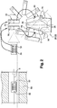
- a polyphase rotary electrical machine 1 forming, in the present exemplary embodiment of the invention, an alternator for a motor vehicle.
- the electric machine 1 can, if desired, be reversible and form an alternator-starter capable of operating in electric motor mode. to start the vehicle's combustion engine and in alternator mode to generate electrical energy.
- This machine 1 comprises a casing 10 and, inside the latter, a rotor 12 integral in rotation with a rotary shaft 14 of axis X, called the rotor shaft, and a stator 16 which surrounds the rotor 12.
- the stator 16 comprises a body 17 formed of a bundle of sheets provided with notches for mounting a stator winding 18 forming chignons on either side of the stator body 17.
- the rotor 12 comprises two pole wheels 20 and 22, each provided with a transverse flange 24 on the periphery of which are connected a plurality of claws 26 extending substantially in the axial direction A.
- Each of the claws 26 has an overall trapezoidal shape when observed in a radial direction R, as can be seen in the figure. figure 2 especially.
- the claws 26 of a pole wheel form with the claws 26 of the other pole wheel interpolar spaces 28 arranged to each receive a magnet structure 30.
- An excitation coil 34 is placed between the flanges 24 of the pole wheels 20 and 22.
- Each pole wheel 20; 22 has a bore forming an internal passage 38 for receiving the shaft 14.
- the pole wheels 20 and 22 are made for example of steel.
- the shaft 14 carries at its front end a pulley 40 belonging to a device for transmitting movement by means of at least one belt (not shown) between the alternator 1 and the combustion engine of the motor vehicle, and to its rear end of slip rings 42 connected by wire links (not shown) to the excitation winding 34 of rotor 12.
- Brushes of a brush holder 44 shown very schematically are arranged so as to rub on the slip rings, in order to supply the winding 34 with electric current.
- the inductor rotor 12 creates an induced alternating current in the stator 16.
- the housing 10 comprises, in the example considered, two parts, namely a front bearing 46 and a rear bearing 48 carrying the brush holder 44.
- the bearings 46 and 48 each carry a ball bearing 50 and 52 respectively for the rotational mounting of the shaft 14.
- the alternator 1 also comprises means for its cooling.
- the bearings 46 and 48 are perforated to allow cooling of the alternator by air circulation.
- the rotor 12 carries, in the example described, at least at one of its axial ends a fan intended to provide air circulation.
- a first ventilation element 54 is for example provided on the front transverse face of the rotor 12 and a second ventilation element 56 is provided on the rear face of the rotor 12.
- Each ventilation element 54 and 56 is provided with a plurality of blades. 58 and 60.
- each pole wheel 20; 22 has six claws 26 so as to define a rotor with 12 interpolar spaces 28.
- rotor 12 may have 2, 4, 6, 8 or 10 interpolar spaces 28, depending on the type of electrical machine desired.
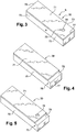
- Each magnet structure 30 comprises a permanent magnet 70, for example of rare earth, and a plate 71 made of non-magnetic material, for example of composite material containing glass fibers.
- the permanent magnet 70 has a substantially rectangular parallelepiped shape.
- This shape of the magnet exhibits invariance by rotating through an angle of 180 ° so that it is impossible to visually distinguish a side face 72 of North polarity and an opposite side face 73 of South polarity, after the magnet 70 has taken its magnetization.
- the magnet structures 30 are passed through a magnetization device 80 arranged to magnetize the magnets 70 of the structures 30 using a magnetic field represented by an arrow B.
- each magnet 70 has North and South polarities respectively on its opposite faces 72 and 73.
- the magnet structures 30 pass through device 80 through Iot, being aligned in parallel.
- the plate 71 has a rectangular shape and entirely covers one face of the permanent magnet 70, this plate 71 being fixed on the magnet 70 before passing through the magnetization device 80.
- each magnet structure 30 comprises an indexing mark 75 .
- the indexing mark 75 comprises an orifice 76 formed in the plate 71, closer to an axial end 77 than to the other end 78.
- first magnet structure 30 For a first magnet structure 30 to be deposited in a first interpolar space 28, the latter is oriented so that the index mark 75 is radially interior, and, for a second magnet structure 30 to be deposited in a second interpolar space 28, this structure 30 is rotated to place it with the indexing mark located on the outside (see figure 2 ).
- the invention thus makes it possible to avoid errors in the orientation of the magnetization of the structures 30, which is particularly advantageous when these structures 30 are put in place manually, the operator using the mark of. magnetization to orient the structures 30.
- magnet structures 30 are fixed on one of the pole wheels 20; 22 before assembly of this wheel with the other pole wheel.
- magnet structures 30 are secured to the pole wheel by magnetization, before being clamped between the two pole wheels 20 and 22.
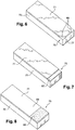
- the plate 71 entirely covers one face of the magnet 70.
- the magnet 70 has an excess length 78 relative to the wafer 71 in the longitudinal direction, on an axial end 77.
- This excess length thus forms an indexing mark 75 within the meaning of the invention, serving to identify a direction of orientation of the magnetization of the magnet structure 30.
- the plate 71 can thus be solid, without an orifice, which makes it possible in particular to simplify its manufacture in terms of cutting operations.
- the magnet structure 30 has in addition to the over-length 78, an orifice 76 in order to distinguish the sides of the structure 30 in a redundant manner.
- the wafer 71 has a length equal to that of the magnet 70, with cutouts 85 on an axial side so as to form an index mark 75.
- cutouts make it possible to quickly verify, with the naked eye, whether the magnet structures are arranged correctly in the interpolar spaces.
- cutouts 85 have for example a triangular shape.
- cutouts can have any other suitable shape.
- the wafer 71 may have a single rounded cutout formed on the middle of an edge of the wafer 71.
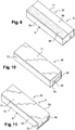
- the plate 71 comprises a portion of reduced thickness 87, extending on an axial side of the magnet 70.
- This portion 87 forms an indexing mark 75 within the meaning of the invention.
- the indexing mark 75 is formed by the shapes and / or dimensions of the plate 71.
- the indexing mark is formed by other means.
- the indexing mark 75 is formed by at least two zones having different optical properties, being in particular of different colors or reflecting properties
- the plate 71 comprises two zones 88 and 89, for example rectangular, of different areas, and having different colors.
- These zones 88 and 89 extend along a width of the magnet structure.
- the zones 88 and 89 of identical surface area extend along a length of the structure.
- the North side (N) can be associated with a first color of zone 89 and the South side (S) with a second color, different from the first color, of zone 88.
- the index mark 75 can, if desired, be formed on the magnet 70, and not on the wafer 71.
- the magnet structure 30 of the figure 10 is an unclaimed example of an index mark comprising a magnet 70 and a plate 71 entirely covering one face of this magnet 70.
- An index mark 75 is made on an axial end face 91 in the form of a notch 90.
- This notch 90 has for example a rectilinear shape.
- any other suitable shape of the notch 90 can be envisaged.
- the notch can be circular.
- the magnet 70 may have a shape with, symmetrically on its two opposite axial ends, rounded corners.
- the wafer 71 can, if desired, cover at least two faces of the magnet 70.
- the plate 71 has a portion 95 bent at right angles and covering a radial face of the permanent magnet 70. This face may be a front or rear face of the magnet.
- This portion 95 is used to define an indexing mark 75 not claimed within the meaning of the invention.
Description
- L'invention concerne notamment un procédé de fabrication d'un rotor de machine électrique tournante, notamment un alternateur.
- Le brevet
FR 2 793 085 - Le brevet
US 7 095 154 décrit un rotor d'alternateur comportant des aimants permanents maintenus dans des espaces interpolaires à l'aide d'éléments de support. Chacun des aimants est positionné de manière non-centrée dans l'espace interpolaire correspondant. - Le brevet
US2004/032183 décrit un rotor comprenant des aimants permanents maintenus dans les espaces interpolaires. Chaque aimant présentant une ouverture d'indexation agencée contre une face latérale d'une roue polaire. Les marque d'indexation n'étant donc pas visible une fois l'aimant monté dans l'espace interpolaire. - Les brevets
US6252330 ,DE10153578 ,US5969459 etGB2331862 - L'invention vise notamment à simplifier le procédé de fabrication d'un rotor, tout en évitant des risques d'erreur de montage des structures à aimant.
- L'invention a ainsi pour objet non revendiqué un procédé de fabrication d'un rotor de machine électrique tournante, notamment un alternateur, le rotor comprenant deux roues polaires définissant entre elles au moins un espace interpolaire agencé pour recevoir au moins une structure à aimant, laquelle comporte au moins une marque d'indexation, le procédé comportant l'étape suivante :
- disposer la structure à aimant contre l'une au moins des roues polaires, en se servant de la marque d'indexation pour repérer un sens d'orientation de l'aimantation de la structure à aimant.
- La présence de marques d'indexation selon l'invention permet de réduire, voire annuler, le risque de montage des structures à aimant sur la roue polaire en les orientant suivant un sens d'aimantation erroné.
- Ces marques d'indexation permettent en outre de vérifier rapidement si toutes les structures à aimant sont disposées correctement dans les espaces interpolaires.
- Le cas échéant, les structures à aimant peuvent être posées sur la roue polaire toutes à l'endroit ou toutes à l'envers, et le collecteur est posé, à la fermeture du circuit électrique de la machine, dans une configuration adéquate en fonction de la position observée des structures à aimant.
- L'invention est particulièrement bien adaptée à un procédé mis en œuvre manuellement.
- Il est également possible de vérifier le circuit électromagnétique de la machine électrique en fin d'assemblage.
- Dans un exemple de mise en oeuvre de l'invention, la structure à aimant est posée contre l'une des roues polaires, avant assemblage de celles-ci.
- En variante, la structure à aimant est insérée dans l'espace interpolaire après assemblage des deux roues polaires.
- La marque d'indexation de la structure à aimant est visible à l'œil nu, permettant par exemple à une personne de repérer une orientation d'aimantation de la structure à aimant.
- Le cas échéant, pour magnétiser les structures à aimant, celles-ci sont disposées parallèlement, suivant une même orientation, lors de leur passage dans un dispositif de magnétisation.
- L'invention permet ainsi d'éviter d'avoir à magnétiser les structures à aimant selon deux sens différents et donc de faire deux groupes d'aimants, ce qui simplifie le procédé.
- De plus manipuler des structures à aimant toutes avec la même orientation d'aimantation par rapport à la marque d'indexation permet d'éviter des confusions lors des différentes étapes de la fabrication du rotor. Il est possible d'utiliser une seule référence de structures à aimant.
- En variante, il est possible, pour magnétiser les structures à aimant, de disposer celles-ci parallèlement, suivant une orientation alternée, lors de leur passage dans un dispositif de magnétisation. Dans ce cas, deux références de structures à aimant peuvent être utilisées.
- Dans un exemple, le rotor comporte une pluralité d'espaces interpolaires, chacun étant apte à recevoir au moins une structure à aimant, et le procédé comporte l'étape suivante :
- à partir d'un ensemble de structures à aimant toutes présentant des pôles Nord et Sud orientés de manière identique par rapport à la marque d'indexation correspondante, prélever et disposer une pluralité de structures à aimant sur l'une au moins des roues polaires dans les espaces interpolaires successifs, selon des orientations alternées d'un espace interpolaire à l'autre.
- Le procédé peut comporter l'étape suivante :
- prélever et faire tourner la structure à aimant d'un angle choisi, notamment en se servant de la marque d'indexation comme repère, en vue de la mettre dans une position adéquate avant de la disposer contre l'une des roues polaires.
- Les étapes ci-dessus peuvent être accomplies manuellement ou, en variante, à l'aide d'un robot muni d'un bras articulé.
- L'invention a pour objet un rotor de machine électrique tournante selon la revendication 1, notamment un alternateur, notamment fabriquée par le procédé tel que défini ci-dessus, caractérisée par le fait qu'il comporte une structure à aimant comportant au moins une marque d'indexation agencée pour permettre de distinguer, visuellement, le sens d'aimantation de cette structure à aimant pour permettre de vérifier rapidement si les structures à aimant sont disposées correctement dans les espaces interpolaires.
- Selon l'invention, la structure à aimant comporte une plaquette et un aimant disposé contre la plaquette, et la marque d'indexation est réalisée au moins partiellement sur la plaquette.
- Cette plaquette sert notamment à retenir l'aimant et joue un rôle d'absorbeur mécanique.
- Si on le souhaite, la marque d'indexation comporte au moins un orifice ou une découpe formé dans la plaquette.
- La marque d'indexation peut comporter une sur-longueur de l'aimant dans le prolongement de la longueur de la plaquette, laquelle sur-longueur est présente uniquement sur un côté de la structure à aimant de manière à distinguer un côté de l'aimant de l'autre.
- En variante, la plaquette peut présenter une sur-longueur par rapport à l'aimant.
- Le cas échéant, la marque d'indexation est formée par au moins deux zones ayant des propriétés électromagnétiques, notamment optiques, différentes, étant par exemple de couleurs ou de propriétés réfléchissantes différentes.
- Ces deux zones de propriétés optiques différentes peuvent s'étendre dans la longueur ou la largeur de la structure à aimant.
- La marque d'indexation est formée, si on le souhaite, par une variation d'épaisseur de l'un de la plaquette et de l'aimant permanent.
- Dans un exemple non revendiqué, la marque d'indexation est réalisée au moins partiellement sur l'aimant.
- La marque d'indexation peut par exemple comporter un arrachement de matière, par exemple une entaille, sur l'aimant ou un signe imprimé sur cet aimant.
- D'une manière générale, la marque d'indexation, qu'elle soit réalisée sur l'aimant ou la plaquette ou les deux à la fois, peut être formée de diverses manières, notamment en créant une discontinuité et/ou une dissymétrie, par exemple par découpe, entaille, impression d'une encre visible ou invisible à l'œil nu, apposition par exemple par collage d'un élément séparé tel qu'une pastille ou une étiquette, etc...
- Dans un exemple de mise en oeuvre de l'invention, l'une au moins des structures à aimant présente une forme sensiblement parallélépipèdique rectangle ou, en variante, avoir une section transversale trapézoïdale.
- Par exemple, la plaquette est fixée par collage sur l'aimant.
- Toutes les structures à aimant présentent un même sens d'aimantation par rapport à la marque d'indexation.
- De préférence, toutes les structures à aimant du rotor sont identiques.
- Avantageusement la structure à aimant comporte un aimant permanent s'étendant sur toute une largeur de l'espace interpolaire.
- L'invention a encore pour objet une machine électrique tournante, notamment un alternateur de véhicule automobile, comportant un rotor tel que précité.
- L'invention pourra être mieux comprise à la lecture de la description détaillée qui va suivre, d'exemples de mise en œuvre non limitatifs de l'invention, et à l'examen du dessin annexé, sur lequel :
- la
figure 1 représente, schématiquement et partiellement, en coupe longitudinale, un alternateur conforme à un exemple de mise en œuvre de l'invention, - la
figure 2 illustre schématiquement des étapes de fabrication d'un rotor de l'alternateur de lafigure 1 , et - les
figures 3 à 11 représentent, schématiquement et partiellement, des exemples de structures à aimant - Dans la suite de la description, les flèches "A" et "R" de la
figure 1 indiquent respectivement des directions axiale et radiale. - On a représenté sur la
figure 1 une machine électrique tournante polyphasée 1 formant, dans le présent exemple de mise en œuvre de l'invention, un alternateur pour véhicule automobile. Bien entendu, la machine électrique 1 peut, si on le souhaite, être réversible et former un alterno-démarreur pouvant fonctionner en mode moteur électrique pour démarrer le moteur à combustion du véhicule et en mode alternateur pour produire de l'énergie électrique. - Cette machine 1 comporte un carter 10 et, à l'intérieur de celui-ci, un rotor 12 solidaire en rotation d'un arbre rotatif 14 d'axe X, appelé arbre de rotor, et un stator 16 qui entoure le rotor 12.
- Le stator 16 comporte un corps 17 formé d'un paquet de tôles doté d'encoches pour le montage d'un bobinage de stator 18 formant des chignons de part et d'autre du corps de stator 17.
- Le rotor 12 comprend deux roues polaires 20 et 22, pourvues chacune d'un flasque transversal 24 sur la périphérie duquel se raccordent une pluralité de griffes 26 s'étendant sensiblement suivant la direction axiale A.
- Chacune des griffes 26 présente globalement une forme trapézoïdale lorsqu'elle est observée suivant une direction radiale R, comme on peut le voir sur la
figure 2 notamment. - Les griffes 26 d'une roue polaire forment avec les griffes 26 de l'autre roue polaire des espaces interpolaires 28 agencés pour recevoir chacun une structure à aimant 30.
- Un bobinage d'excitation 34 est mis en place entre les flasques 24 des roues polaires 20 et 22.
- Chaque roue polaire 20 ; 22 comporte un alésage formant un passage intérieur 38 pour recevoir l'arbre 14.
- Les roues polaires 20 et 22 sont réalisées par exemple en acier.
- L'arbre 14 porte à son extrémité avant une poulie 40 appartenant à un dispositif de transmission de mouvement par l'intermédiaire d'au moins une courroie (non représentée) entre l'alternateur 1 et le moteur à combustion du véhicule automobile, et à son extrémité arrière des bagues collectrices 42 reliées par des liaisons filaires (non représentées) au bobinage d'excitation 34 du rotor 12.
- Des balais d'un porte-balais 44 représenté de manière très schématique sont disposés de façon à frotter sur les bagues collectrices, afin d'alimenter le bobinage 34 en courant électrique.
- Lorsque l'arbre 14 est en rotation et le bobinage d'excitation 34 activé par une alimentation électrique, le rotor inducteur 12 crée un courant induit alternatif dans le stator 16.
- Le carter 10 comporte, dans l'exemple considéré, deux parties, à savoir un palier avant 46 et un palier arrière 48 portant le porte-balais 44.
- Les paliers 46 et 48 portent chacun un roulement à billes respectivement 50 et 52 pour le montage à rotation de l'arbre 14.
- L'alternateur 1 comporte également des moyens pour son refroidissement.
- Par exemple, comme illustré à la
figure 1 , les paliers 46 et 48 sont ajourés pour permettre le refroidissement de l'alternateur par circulation d'air. - Le rotor 12 porte, dans l'exemple décrit, au moins à l'une de ses extrémités axiales un ventilateur destiné à assurer une circulation de l'air. Un premier élément de ventilation 54 est par exemple prévu sur la face transversale avant du rotor 12 et un deuxième élément de ventilation 56 est prévu sur la face arrière du rotor 12. Chaque élément de ventilation 54 et 56 est pourvu d'une pluralité de pâles 58 et 60.
- Dans l'exemple de réalisation décrit, chaque roue polaire 20 ; 22 comporte six griffes 26 de manière à définir un rotor avec 12 espaces interpolaires 28.
- En variante, le rotor 12 peut comporter 2, 4, 6, 8 ou 10 espaces interpolaires 28, en fonction du type de machine électrique souhaité.
- On va maintenant décrire notamment en référence à la
figure 2 différentes étapes de fabrication du rotor 12, notamment en liaison avec le montage des structures à aimant 30 dans les espaces interpolaires 28. - Chaque structure à aimant 30 comprend un aimant permanent 70, par exemple en terre rare, et une plaquette 71 réalisée en matériau amagnétique, par exemple en matériau composite contenant des fibres de verre.
- Dans l'exemple considéré, illustré à la
figure 3 , l'aimant permanent 70 présente une forme sensiblement parallélépipédique rectangle. - Cette forme de l'aimant présente une invariance par une rotation d'un angle de 180° de sorte qu'il est impossible de distinguer visuellement une face latérale 72 de polarité Nord et une face latérale opposée 73 de polarité Sud, après que l'aimant 70 ait pris son aimantation.
- Dans le procédé illustré à la
figure 2 , les structures à aimant 30 sont passés dans un dispositif de magnétisation 80 agencé pour magnétiser les aimants 70 des structures 30 à l'aide d'un champ magnétique représenté par une flèche B. - Après ce passage, chaque aimant 70 présente des polarités Nord et Sud respectivement sur ses faces opposées 72 et 73.
- Les structures à aimant 30 passe dans le dispositif 80 par Iot, en étant alignées parallèlement.
- Dans l'exemple décrit, la plaquette 71 présente une forme rectangulaire et recouvre entièrement une face de l'aimant permanent 70, cette plaquette 71 étant fixée sur l'aimant 70 avant passage dans le dispositif de magnétisation 80.
- Afin de permettre la distinction visuelle entre les faces 72 (Nord) et 73 (Sud) de l'aimant 70, et donc la reconnaissance du sens d'aimantation de cet aimant 70, chaque structure à aimant 30 comporte une marque d'indexation 75.
- Dans l'exemple illustré en référence à la
figure 3 , la marque d'indexation 75 comporte un orifice 76 formé dans la plaquette 71, plus proche d'une extrémité axiale 77 que de l'autre extrémité 78. - Ainsi, en vue de déposer sur l'une des roues polaires 20 ; 22 les structures à aimant 30, en alternant le sens d'aimantation des aimants 70 d'un espace interpolaire au suivant, il est possible de se servir de la marque d'indexation 75 pour repérer visuellement un sens d'orientation de l'aimantation de la structure 30.
- Par exemple, pour une première structure à aimant 30 à déposer dans un premier espace interpolaire 28, celle-ci est orientée de manière à ce que la marque d'indexation 75 soit radialement intérieure, et, pour une deuxième structure à aimant 30 à déposer dans un deuxième espace interpolaire 28, cette structure 30 est tournée pour la disposer avec la marque d'indexation située extérieurement (voir
figure 2 ). - L'invention permet ainsi d'éviter des erreurs dans l'orientation de l'aimantation des structures 30, ce qui est particulièrement avantageux lorsque ces structures 30 sont mises en place de façon manuelle, l'opérateur s'aidant de la marque d'aimantation pour orienter les structures 30.
- Il est à noter que les structures à aimant 30 sont fixées sur l'une des roues polaires 20 ; 22 avant assemblage de cette roue avec l'autre roue polaire.
- Ces structures à aimant 30 sont solidarisées à la roue polaire par aimantation, avant d'être enserrées entre les deux roues polaires 20 et 22.
- Dans l'exemple qui vient d'être décrit, la plaquette 71 recouvre entièrement une face de l'aimant 70.
- En variante, comme illustré sur la
figure 4 , l'aimant 70 présente une sur-longueur 78 par rapport à la plaquette 71 dans la direction longitudinale, sur une extrémité axiale 77. - Cette sur-longueur forme ainsi une marque d'indexation 75 au sens de l'invention, servant pour repérer un sens d'orientation de l'aimantation de la structure à aimant 30.
- La plaquette 71 peut ainsi être pleine, sans orifice, ce qui permet notamment de simplifier sa fabrication au niveau des opérations de coupe.
- En variante, comme illustré sur la
figure 5 , la structure à aimant 30 présente en plus de la sur-longueur 78, un orifice 76 en vue de distinguer les côtés de la structure 30 de manière redondante. - Dans l'exemple illustré à la
figure 6 , la plaquette 71 présente une longueur égale à celle de l'aimant 70, avec des découpes 85 sur un côté axial de manière à former une marque d'indexation 75. Lorsque les découpes permettent de vérifier rapidement, à l'œil nu, si les structures à aimant sont disposées correctement dans les espaces interpolaires. - Ces découpes 85 présentent par exemple une forme triangulaire.
- Bien entendu, ces découpes peuvent présenter toutes autres formes appropriées.
- Par exemple, la plaquette 71 peut présenter une seule découpe arrondie formée sur le milieu d'un bord de la plaquette 71.
- Dans l'exemple illustré à la
figure 7 , la plaquette 71 comporte une portion d'épaisseur réduite 87, s'étendant sur un côté axial de l'aimant 70. - Cette portion 87 forme une marque d'indexation 75 au sens de l'invention.
- Dans les exemples qui viennent d'être décrits, la marque d'indexation 75 est formée par des formes et/ou dimensions de la plaquette 71.
- Bien entendu, on ne sort pas du cadre de la présente invention lorsque la marque d'indexation est formée par d'autres moyens.
- Comme illustré sur la
figure 8 , la marque d'indexation 75 est formée par au moins deux zones ayant des propriétés optiques différentes, étant notamment de couleurs ou de propriétés réfléchissantes différentes - Dans l'exemple considéré, la plaquette 71 comporte deux zones 88 et 89, par exemple rectangulaires, de superficies différentes, et présentant des couleurs différentes.
- Ces zones 88 et 89 s'étendent suivant une largeur de la structure à aimant.
- En variante, comme illustré sur la
figure 9 , les zones 88 et 89 de superficie identique s'étendent suivant une longueur de la structure. - Par exemple, le côté Nord (N) peut être associé à une première couleur de la zone 89 et le côté Sud (S) à une deuxième couleur, différente de la première couleur, de la zone 88.
- Lors de la pose des structures sur une roue polaire, il est possible de disposer les structures à aimant de manière à ce que tous les côtés de la même couleur soient sur la roue polaire.
- La marque d'indexation 75 peut, si on le souhaite, être formée sur l'aimant 70, et non sur la plaquette 71.
- La structure à aimant 30 de la
figure 10 est un exemple non revendiqué d'un marque d'indexation comportant un aimant 70 et une plaquette 71 recouvrant entièrement une face de cet aimant 70. - Une marque d'indexation 75 est réalisée sur une face d'extrémité axiale 91 sous la forme d'une entaille 90.
- Cette entaille 90 présente par exemple une forme rectiligne.
- En variante, toute autre forme appropriée de l'entaille 90 peut être envisagée.
- Par exemple, l'entaille peut être circulaire.
- Bien entendu, l'invention n'est pas limitée aux exemples de mise en œuvre qui viennent d'être décrits.
- Par exemple, l'aimant 70 peut présenter une forme avec, symétriquement sur ses deux extrémités axiales opposées, des coins arrondis.
- La plaquette 71 peut, si on le souhaite, recouvrir au moins deux faces de l'aimant 70.
- Par exemple, comme illustré sur la
figure 11 , la plaquette 71 présente une portion 95 repliée à angle droit et recouvrant une face radiale de l'aimant permanent 70. Cette face peut être une face avant ou arrière de l'aimant. - Cette portion 95 sert à définir une marque d'indexation 75 non-revendiquée au sens de l'invention.
Claims (8)
- Rotor (12) de machine électrique tournante, notamment un alternateur de véhicule automobile, comportant :- deux roues polaires (20, 22), pourvues chacune d'un flasque transversal (24) sur la périphérie duquel se raccordent une pluralité de griffes (26) s'étendant sensiblement suivant une direction axiale (A), les griffes d'une roue polaire formant avec les griffes de l'autre roue polaire des espaces interpolaires (28) et- une pluralité de structures à aimant (30) étant montées dans les espaces interpolaires (28), les espaces interpolaires étant agencés pour recevoir chacun une structure à aimant (30) ;le rotor étant caractérisé en ce que chaque structure à aimant (30) comporte au moins une marque d'indexation (75) agencée pour permettre de distinguer visuellement à l'œil nu le sens d'aimantation de cette structure à aimant et pour permettre de vérifier rapidement si les structures à aimant sont disposées correctement dans les espaces interpolaires (28), toutes les structures à aimant (30) présentant un même sens d'aimantation par rapport à la marque d'indexation (75), et en ce que chaque structure à aimant (30) comporte une plaquette (71) et un aimant (70) disposé contre la plaquette, la marque d'indexation (75) étant réalisée au moins partiellement sur la plaquette.
- Rotor selon la revendication précédente, caractérisé en ce que la marque d'indexation (75) comporte au moins un orifice (76) formé dans la plaquette (71).
- Rotor selon l'une quelconque des revendications précédentes, caractérisé en ce que la marque d'indexation (75) comporte une sur-longueur (78) de l'aimant dans le prolongement de la longueur de la plaquette.
- Rotor selon la revendication 1, caractérisé en ce que la marque d'indexation (75) est formée par une variation d'épaisseur de la plaquette (71) ou de l'aimant permanent (70).
- Rotor selon la revendication 1, caractérisé par le fait que la marque d'indexation (75) est formée par au moins deux zones (88, 89) ayant des propriétés optiques différentes, étant notamment de couleurs différentes.
- Rotor selon l'une quelconque des revendications précédentes, caractérisé par le fait que les structures à aimant présentent une forme sensiblement parallélépipédique rectangle.
- Rotor selon l'une quelconque des revendications précédentes, caractérisé par le fait que toutes les structures à aimant sont identiques.
- Machine électrique tournante, notamment un alternateur (1) de véhicule automobile, comportant un rotor selon l'une quelconque des revendications précédentes.
Applications Claiming Priority (2)
| Application Number | Priority Date | Filing Date | Title |
|---|---|---|---|
| FR0759297A FR2924284A1 (fr) | 2007-11-26 | 2007-11-26 | Procede de fabrication d'un rotor de machine electrique tournante, notamment un alternateur |
| PCT/FR2008/052115 WO2009071827A2 (fr) | 2007-11-26 | 2008-11-24 | Procede de fabrication d'un rotor de machine electrique tournante, notamment un alternateur |
Publications (2)
| Publication Number | Publication Date |
|---|---|
| EP2218158A2 EP2218158A2 (fr) | 2010-08-18 |
| EP2218158B1 true EP2218158B1 (fr) | 2020-12-09 |
Family
ID=39666102
Family Applications (1)
| Application Number | Title | Priority Date | Filing Date |
|---|---|---|---|
| EP08857174.0A Active EP2218158B1 (fr) | 2007-11-26 | 2008-11-24 | Rotor de machine electrique comprenant des griffes et structures a aimant dans les espaces interpolaires |
Country Status (7)
| Country | Link |
|---|---|
| US (1) | US8531081B2 (fr) |
| EP (1) | EP2218158B1 (fr) |
| KR (1) | KR20100095538A (fr) |
| CN (1) | CN101874334B (fr) |
| BR (1) | BRPI0817900B8 (fr) |
| FR (1) | FR2924284A1 (fr) |
| WO (1) | WO2009071827A2 (fr) |
Families Citing this family (1)
| Publication number | Priority date | Publication date | Assignee | Title |
|---|---|---|---|---|
| CN103066772B (zh) * | 2012-12-26 | 2015-04-01 | 南车株洲电机有限公司 | 一种永磁电机磁钢装配工装 |
Family Cites Families (16)
| Publication number | Priority date | Publication date | Assignee | Title |
|---|---|---|---|---|
| USRE24943E (en) * | 1961-02-28 | Electrically controlled magnetic movement | ||
| US2836773A (en) * | 1955-04-29 | 1958-05-27 | Allard Instr Corp | Electrically controlled magnetic movement |
| US5858158A (en) * | 1992-03-11 | 1999-01-12 | Mark Iv Industries Limited | Electromagnetic disk and method of making |
| JP3646446B2 (ja) * | 1997-01-14 | 2005-05-11 | 株式会社デンソー | ランデルコア型回転電機 |
| JP3541920B2 (ja) * | 1997-10-27 | 2004-07-14 | 三菱電機株式会社 | 回転電機の回転子およびその製造方法 |
| JP3767136B2 (ja) * | 1997-11-13 | 2006-04-19 | 三菱電機株式会社 | 回転電機の回転子及びその製造方法 |
| FR2786625B1 (fr) * | 1998-11-30 | 2001-02-16 | Valeo Equip Electr Moteur | Alternateur de vehicule automobile a aimants interpolaires |
| FR2793085B1 (fr) * | 1999-04-30 | 2001-07-13 | Valeo Equip Electr Moteur | Alternateur pour vehicule automobile a aimants interpolaires |
| DE19951115A1 (de) * | 1999-10-23 | 2001-05-03 | Bosch Gmbh Robert | Elektrische Maschine |
| DE10153578B4 (de) * | 2000-11-06 | 2012-01-26 | Denso Corporation | Wechselstromgenerator für Fahrzeuge mit Permanentmagneten im Rotor und Verfahren zur Herstellung desselben |
| US6452301B1 (en) * | 2001-11-02 | 2002-09-17 | Electric Boat Corporation | Magnet retention arrangement for high speed rotors |
| JP3789361B2 (ja) * | 2002-01-18 | 2006-06-21 | 株式会社デンソー | 交流発電機 |
| JP3882725B2 (ja) * | 2002-03-12 | 2007-02-21 | 株式会社デンソー | 車両用回転電機 |
| JP4396471B2 (ja) * | 2004-10-01 | 2010-01-13 | 株式会社デンソー | 車両用回転電機およびその製造方法 |
| JP4735980B2 (ja) * | 2006-08-23 | 2011-07-27 | 株式会社デンソー | 車両用交流発電機及びその製造方法 |
| FR2906942B1 (fr) * | 2006-10-10 | 2014-07-04 | Valeo Equip Electr Moteur | Rotor a griffes muni d'elements ferromagnetiques interpolaires de largeur optimisee et machine tournante equipe d'un tel rotor |
-
2007
- 2007-11-26 FR FR0759297A patent/FR2924284A1/fr active Pending
-
2008
- 2008-11-24 US US12/743,888 patent/US8531081B2/en active Active
- 2008-11-24 CN CN2008801179045A patent/CN101874334B/zh active Active
- 2008-11-24 KR KR1020107011391A patent/KR20100095538A/ko not_active Application Discontinuation
- 2008-11-24 BR BRPI0817900A patent/BRPI0817900B8/pt active IP Right Grant
- 2008-11-24 WO PCT/FR2008/052115 patent/WO2009071827A2/fr active Application Filing
- 2008-11-24 EP EP08857174.0A patent/EP2218158B1/fr active Active
Non-Patent Citations (1)
| Title |
|---|
| None * |
Also Published As
| Publication number | Publication date |
|---|---|
| WO2009071827A2 (fr) | 2009-06-11 |
| CN101874334A (zh) | 2010-10-27 |
| US8531081B2 (en) | 2013-09-10 |
| CN101874334B (zh) | 2013-03-27 |
| BRPI0817900A2 (pt) | 2015-03-31 |
| US20100295400A1 (en) | 2010-11-25 |
| KR20100095538A (ko) | 2010-08-31 |
| BRPI0817900B8 (pt) | 2024-02-20 |
| EP2218158A2 (fr) | 2010-08-18 |
| FR2924284A1 (fr) | 2009-05-29 |
| BRPI0817900B1 (pt) | 2023-12-26 |
| WO2009071827A3 (fr) | 2009-10-08 |
Similar Documents
| Publication | Publication Date | Title |
|---|---|---|
| EP3602740B1 (fr) | Moteur ou génératrice électromagnétique comportant un rotor à structures aimantées comprenant des aimants unitaires et un stator à bobinages concentriques | |
| EP1362407B1 (fr) | Machine tournante perfectionnee pour vehicule automobile | |
| FR2884367A1 (fr) | Cible appartenant a des moyens de suivi de la position d'un rotor d'une machine electrique tournante et machine electrique tournante comportant une telle cible | |
| EP3028373A2 (fr) | Rotor à griffes comportant un clip de fixation d'un fil d'extremite du bobinage et machine electrique associee | |
| WO2008074954A1 (fr) | Machine electrique tournante, en particulier pour un demarreur de vehicule automobile | |
| FR2920259A1 (fr) | Machine electrique tournante, en particulier pour un demarreur automobile | |
| EP2218158B1 (fr) | Rotor de machine electrique comprenant des griffes et structures a aimant dans les espaces interpolaires | |
| EP2145376B1 (fr) | Procede de fabrication d'un rotor de machine electrique tournante, notamment un alternateur | |
| FR2910192A1 (fr) | Machine electrique tournante, en particulier pour un demarreur de vehicule automobile | |
| EP2878071B1 (fr) | Bobinage pour un élément stator d'un moteur ou génératrice à aimants permanents à au moins une branche rigide et d'un seul tenant et son procédé de fabrication | |
| WO2019011760A1 (fr) | Rotor de machine électrique tournante muni de languettes de maintien d'aimants permanents | |
| EP1351367A1 (fr) | Machine électrique à stator et/ou rotor modulaire et échangeur de chaleur de véhicule automobile comprenant une telle machine | |
| FR3064131A1 (fr) | Rotor de machine electrique tournante muni de flasques d'equilibrage ameliores | |
| WO2018158517A1 (fr) | Rotor de machine électrique tournante munie d'au moins un roulement à ventilateur intégré | |
| EP4111574B1 (fr) | Rotor pour moteur électrique équipé d'aimants permanents en matière plastique | |
| WO2018020188A1 (fr) | Machine electrique tournante munie d'un stator avec un bobinage epingle | |
| WO2019020490A1 (fr) | Rotor de machine électrique tournante muni d'une couche de résine dans les cavités d'aimants permanents | |
| EP0762601A1 (fr) | Alternateur à structure de rotor perfectionnée, notamment pour véhicule automobile | |
| EP3646437B1 (fr) | Rotor a aimants permanents pour moteur electrique et dispositif de pulsion d'air correspondant | |
| WO2016146909A1 (fr) | Rotor de machine electrique tournante a configuration d'aimants permanents optimisee | |
| FR3055485A1 (fr) | Rotor de machine electrique tournante muni d'au moins une portion deformable pour le remplissage d'une cavite | |
| EP3053789B1 (fr) | Roue d'entraînement et système d'entrainement associé | |
| FR3053178A1 (fr) | Machine electrique tournante a rotor mono-levre | |
| FR3105634A1 (fr) | Machine électrique tournante ayant un ratio de dimensions minimisant le bruit | |
| WO2023166443A1 (fr) | Moteur électromagnétique à concentration de flux magnetiques |
Legal Events
| Date | Code | Title | Description |
|---|---|---|---|
| PUAI | Public reference made under article 153(3) epc to a published international application that has entered the european phase |
Free format text: ORIGINAL CODE: 0009012 |
|
| 17P | Request for examination filed |
Effective date: 20100603 |
|
| AK | Designated contracting states |
Kind code of ref document: A2 Designated state(s): AT BE BG CH CY CZ DE DK EE ES FI FR GB GR HR HU IE IS IT LI LT LU LV MC MT NL NO PL PT RO SE SI SK TR |
|
| AX | Request for extension of the european patent |
Extension state: AL BA MK RS |
|
| RIN1 | Information on inventor provided before grant (corrected) |
Inventor name: PFLEGER, ALEXANDRE Inventor name: BILTERYST, PIERRE-YVES Inventor name: GAS, OLIVIER |
|
| DAX | Request for extension of the european patent (deleted) | ||
| STAA | Information on the status of an ep patent application or granted ep patent |
Free format text: STATUS: EXAMINATION IS IN PROGRESS |
|
| 17Q | First examination report despatched |
Effective date: 20180313 |
|
| REG | Reference to a national code |
Ref country code: DE Ref legal event code: R079 Ref document number: 602008063559 Country of ref document: DE Free format text: PREVIOUS MAIN CLASS: H02K0001220000 Ipc: H02K0021040000 |
|
| GRAP | Despatch of communication of intention to grant a patent |
Free format text: ORIGINAL CODE: EPIDOSNIGR1 |
|
| STAA | Information on the status of an ep patent application or granted ep patent |
Free format text: STATUS: GRANT OF PATENT IS INTENDED |
|
| RIC1 | Information provided on ipc code assigned before grant |
Ipc: H02K 1/22 20060101ALI20200615BHEP Ipc: H02K 21/04 20060101AFI20200615BHEP |
|
| INTG | Intention to grant announced |
Effective date: 20200629 |
|
| GRAS | Grant fee paid |
Free format text: ORIGINAL CODE: EPIDOSNIGR3 |
|
| GRAA | (expected) grant |
Free format text: ORIGINAL CODE: 0009210 |
|
| STAA | Information on the status of an ep patent application or granted ep patent |
Free format text: STATUS: THE PATENT HAS BEEN GRANTED |
|
| AK | Designated contracting states |
Kind code of ref document: B1 Designated state(s): AT BE BG CH CY CZ DE DK EE ES FI FR GB GR HR HU IE IS IT LI LT LU LV MC MT NL NO PL PT RO SE SI SK TR |
|
| REG | Reference to a national code |
Ref country code: GB Ref legal event code: FG4D Free format text: NOT ENGLISH |
|
| REG | Reference to a national code |
Ref country code: AT Ref legal event code: REF Ref document number: 1344396 Country of ref document: AT Kind code of ref document: T Effective date: 20201215 Ref country code: CH Ref legal event code: EP |
|
| REG | Reference to a national code |
Ref country code: DE Ref legal event code: R096 Ref document number: 602008063559 Country of ref document: DE |
|
| REG | Reference to a national code |
Ref country code: IE Ref legal event code: FG4D Free format text: LANGUAGE OF EP DOCUMENT: FRENCH |
|
| PG25 | Lapsed in a contracting state [announced via postgrant information from national office to epo] |
Ref country code: FI Free format text: LAPSE BECAUSE OF FAILURE TO SUBMIT A TRANSLATION OF THE DESCRIPTION OR TO PAY THE FEE WITHIN THE PRESCRIBED TIME-LIMIT Effective date: 20201209 Ref country code: NO Free format text: LAPSE BECAUSE OF FAILURE TO SUBMIT A TRANSLATION OF THE DESCRIPTION OR TO PAY THE FEE WITHIN THE PRESCRIBED TIME-LIMIT Effective date: 20210309 Ref country code: GR Free format text: LAPSE BECAUSE OF FAILURE TO SUBMIT A TRANSLATION OF THE DESCRIPTION OR TO PAY THE FEE WITHIN THE PRESCRIBED TIME-LIMIT Effective date: 20210310 |
|
| REG | Reference to a national code |
Ref country code: AT Ref legal event code: MK05 Ref document number: 1344396 Country of ref document: AT Kind code of ref document: T Effective date: 20201209 |
|
| PG25 | Lapsed in a contracting state [announced via postgrant information from national office to epo] |
Ref country code: SE Free format text: LAPSE BECAUSE OF FAILURE TO SUBMIT A TRANSLATION OF THE DESCRIPTION OR TO PAY THE FEE WITHIN THE PRESCRIBED TIME-LIMIT Effective date: 20201209 Ref country code: LV Free format text: LAPSE BECAUSE OF FAILURE TO SUBMIT A TRANSLATION OF THE DESCRIPTION OR TO PAY THE FEE WITHIN THE PRESCRIBED TIME-LIMIT Effective date: 20201209 Ref country code: BG Free format text: LAPSE BECAUSE OF FAILURE TO SUBMIT A TRANSLATION OF THE DESCRIPTION OR TO PAY THE FEE WITHIN THE PRESCRIBED TIME-LIMIT Effective date: 20210309 |
|
| REG | Reference to a national code |
Ref country code: NL Ref legal event code: MP Effective date: 20201209 |
|
| PG25 | Lapsed in a contracting state [announced via postgrant information from national office to epo] |
Ref country code: HR Free format text: LAPSE BECAUSE OF FAILURE TO SUBMIT A TRANSLATION OF THE DESCRIPTION OR TO PAY THE FEE WITHIN THE PRESCRIBED TIME-LIMIT Effective date: 20201209 Ref country code: NL Free format text: LAPSE BECAUSE OF FAILURE TO SUBMIT A TRANSLATION OF THE DESCRIPTION OR TO PAY THE FEE WITHIN THE PRESCRIBED TIME-LIMIT Effective date: 20201209 |
|
| REG | Reference to a national code |
Ref country code: LT Ref legal event code: MG9D |
|
| PG25 | Lapsed in a contracting state [announced via postgrant information from national office to epo] |
Ref country code: CZ Free format text: LAPSE BECAUSE OF FAILURE TO SUBMIT A TRANSLATION OF THE DESCRIPTION OR TO PAY THE FEE WITHIN THE PRESCRIBED TIME-LIMIT Effective date: 20201209 Ref country code: EE Free format text: LAPSE BECAUSE OF FAILURE TO SUBMIT A TRANSLATION OF THE DESCRIPTION OR TO PAY THE FEE WITHIN THE PRESCRIBED TIME-LIMIT Effective date: 20201209 Ref country code: SK Free format text: LAPSE BECAUSE OF FAILURE TO SUBMIT A TRANSLATION OF THE DESCRIPTION OR TO PAY THE FEE WITHIN THE PRESCRIBED TIME-LIMIT Effective date: 20201209 Ref country code: RO Free format text: LAPSE BECAUSE OF FAILURE TO SUBMIT A TRANSLATION OF THE DESCRIPTION OR TO PAY THE FEE WITHIN THE PRESCRIBED TIME-LIMIT Effective date: 20201209 Ref country code: PT Free format text: LAPSE BECAUSE OF FAILURE TO SUBMIT A TRANSLATION OF THE DESCRIPTION OR TO PAY THE FEE WITHIN THE PRESCRIBED TIME-LIMIT Effective date: 20210409 Ref country code: LT Free format text: LAPSE BECAUSE OF FAILURE TO SUBMIT A TRANSLATION OF THE DESCRIPTION OR TO PAY THE FEE WITHIN THE PRESCRIBED TIME-LIMIT Effective date: 20201209 |
|
| PG25 | Lapsed in a contracting state [announced via postgrant information from national office to epo] |
Ref country code: AT Free format text: LAPSE BECAUSE OF FAILURE TO SUBMIT A TRANSLATION OF THE DESCRIPTION OR TO PAY THE FEE WITHIN THE PRESCRIBED TIME-LIMIT Effective date: 20201209 Ref country code: PL Free format text: LAPSE BECAUSE OF FAILURE TO SUBMIT A TRANSLATION OF THE DESCRIPTION OR TO PAY THE FEE WITHIN THE PRESCRIBED TIME-LIMIT Effective date: 20201209 |
|
| REG | Reference to a national code |
Ref country code: DE Ref legal event code: R097 Ref document number: 602008063559 Country of ref document: DE |
|
| PG25 | Lapsed in a contracting state [announced via postgrant information from national office to epo] |
Ref country code: IS Free format text: LAPSE BECAUSE OF FAILURE TO SUBMIT A TRANSLATION OF THE DESCRIPTION OR TO PAY THE FEE WITHIN THE PRESCRIBED TIME-LIMIT Effective date: 20210409 |
|
| PLBE | No opposition filed within time limit |
Free format text: ORIGINAL CODE: 0009261 |
|
| STAA | Information on the status of an ep patent application or granted ep patent |
Free format text: STATUS: NO OPPOSITION FILED WITHIN TIME LIMIT |
|
| PG25 | Lapsed in a contracting state [announced via postgrant information from national office to epo] |
Ref country code: IT Free format text: LAPSE BECAUSE OF FAILURE TO SUBMIT A TRANSLATION OF THE DESCRIPTION OR TO PAY THE FEE WITHIN THE PRESCRIBED TIME-LIMIT Effective date: 20201209 |
|
| 26N | No opposition filed |
Effective date: 20210910 |
|
| PG25 | Lapsed in a contracting state [announced via postgrant information from national office to epo] |
Ref country code: SI Free format text: LAPSE BECAUSE OF FAILURE TO SUBMIT A TRANSLATION OF THE DESCRIPTION OR TO PAY THE FEE WITHIN THE PRESCRIBED TIME-LIMIT Effective date: 20201209 Ref country code: ES Free format text: LAPSE BECAUSE OF FAILURE TO SUBMIT A TRANSLATION OF THE DESCRIPTION OR TO PAY THE FEE WITHIN THE PRESCRIBED TIME-LIMIT Effective date: 20201209 Ref country code: DK Free format text: LAPSE BECAUSE OF FAILURE TO SUBMIT A TRANSLATION OF THE DESCRIPTION OR TO PAY THE FEE WITHIN THE PRESCRIBED TIME-LIMIT Effective date: 20201209 |
|
| PG25 | Lapsed in a contracting state [announced via postgrant information from national office to epo] |
Ref country code: IS Free format text: LAPSE BECAUSE OF FAILURE TO SUBMIT A TRANSLATION OF THE DESCRIPTION OR TO PAY THE FEE WITHIN THE PRESCRIBED TIME-LIMIT Effective date: 20210409 |
|
| PG25 | Lapsed in a contracting state [announced via postgrant information from national office to epo] |
Ref country code: MC Free format text: LAPSE BECAUSE OF FAILURE TO SUBMIT A TRANSLATION OF THE DESCRIPTION OR TO PAY THE FEE WITHIN THE PRESCRIBED TIME-LIMIT Effective date: 20201209 |
|
| REG | Reference to a national code |
Ref country code: CH Ref legal event code: PL |
|
| GBPC | Gb: european patent ceased through non-payment of renewal fee |
Effective date: 20211124 |
|
| PG25 | Lapsed in a contracting state [announced via postgrant information from national office to epo] |
Ref country code: LU Free format text: LAPSE BECAUSE OF NON-PAYMENT OF DUE FEES Effective date: 20211124 Ref country code: BE Free format text: LAPSE BECAUSE OF NON-PAYMENT OF DUE FEES Effective date: 20211130 |
|
| REG | Reference to a national code |
Ref country code: BE Ref legal event code: MM Effective date: 20211130 |
|
| PG25 | Lapsed in a contracting state [announced via postgrant information from national office to epo] |
Ref country code: LI Free format text: LAPSE BECAUSE OF NON-PAYMENT OF DUE FEES Effective date: 20211130 Ref country code: CH Free format text: LAPSE BECAUSE OF NON-PAYMENT OF DUE FEES Effective date: 20211130 |
|
| PG25 | Lapsed in a contracting state [announced via postgrant information from national office to epo] |
Ref country code: IE Free format text: LAPSE BECAUSE OF NON-PAYMENT OF DUE FEES Effective date: 20211124 Ref country code: GB Free format text: LAPSE BECAUSE OF NON-PAYMENT OF DUE FEES Effective date: 20211124 |
|
| PG25 | Lapsed in a contracting state [announced via postgrant information from national office to epo] |
Ref country code: HU Free format text: LAPSE BECAUSE OF FAILURE TO SUBMIT A TRANSLATION OF THE DESCRIPTION OR TO PAY THE FEE WITHIN THE PRESCRIBED TIME-LIMIT; INVALID AB INITIO Effective date: 20081124 Ref country code: CY Free format text: LAPSE BECAUSE OF FAILURE TO SUBMIT A TRANSLATION OF THE DESCRIPTION OR TO PAY THE FEE WITHIN THE PRESCRIBED TIME-LIMIT Effective date: 20201209 |
|
| P01 | Opt-out of the competence of the unified patent court (upc) registered |
Effective date: 20230528 |
|
| PGFP | Annual fee paid to national office [announced via postgrant information from national office to epo] |
Ref country code: FR Payment date: 20231124 Year of fee payment: 16 Ref country code: DE Payment date: 20231107 Year of fee payment: 16 |