EP2218158B1 - Rotoranordnung für eine elektrische maschine klauenpole und magnetstrukturen in den polenluecken aufweisend - Google Patents
Rotoranordnung für eine elektrische maschine klauenpole und magnetstrukturen in den polenluecken aufweisend Download PDFInfo
- Publication number
- EP2218158B1 EP2218158B1 EP08857174.0A EP08857174A EP2218158B1 EP 2218158 B1 EP2218158 B1 EP 2218158B1 EP 08857174 A EP08857174 A EP 08857174A EP 2218158 B1 EP2218158 B1 EP 2218158B1
- Authority
- EP
- European Patent Office
- Prior art keywords
- magnet
- structures
- rotor
- plate
- indexing mark
- Prior art date
- Legal status (The legal status is an assumption and is not a legal conclusion. Google has not performed a legal analysis and makes no representation as to the accuracy of the status listed.)
- Active
Links
Images

Classifications
-
- H—ELECTRICITY
- H02—GENERATION; CONVERSION OR DISTRIBUTION OF ELECTRIC POWER
- H02K—DYNAMO-ELECTRIC MACHINES
- H02K21/00—Synchronous motors having permanent magnets; Synchronous generators having permanent magnets
- H02K21/02—Details
- H02K21/04—Windings on magnets for additional excitation ; Windings and magnets for additional excitation
- H02K21/042—Windings on magnets for additional excitation ; Windings and magnets for additional excitation with permanent magnets and field winding both rotating
- H02K21/044—Rotor of the claw pole type
-
- Y—GENERAL TAGGING OF NEW TECHNOLOGICAL DEVELOPMENTS; GENERAL TAGGING OF CROSS-SECTIONAL TECHNOLOGIES SPANNING OVER SEVERAL SECTIONS OF THE IPC; TECHNICAL SUBJECTS COVERED BY FORMER USPC CROSS-REFERENCE ART COLLECTIONS [XRACs] AND DIGESTS
- Y10—TECHNICAL SUBJECTS COVERED BY FORMER USPC
- Y10T—TECHNICAL SUBJECTS COVERED BY FORMER US CLASSIFICATION
- Y10T29/00—Metal working
- Y10T29/49—Method of mechanical manufacture
- Y10T29/49002—Electrical device making
- Y10T29/49009—Dynamoelectric machine
- Y10T29/49012—Rotor
Definitions
- the invention relates in particular to a method of manufacturing a rotor of a rotating electrical machine, in particular an alternator.
- the patent FR 2 793 085 describes an alternator for a motor vehicle, comprising a stator and a rotor.
- the rotor has a winding and two pole wheels each provided with a plurality of claws.
- the wheels define between them, at the level of the claws, interpolar spaces that can each receive a permanent magnet structure, in particular made of rare earth.
- the direction of magnetization of these magnet structures must be alternated from one interpolar space to the next.
- these magnet structures are arranged in two distinct groups, according to their direction of magnetization. However, these two groups cannot be distinguished visually. Thus when mounting the magnet structures in the interpolar spaces of the rotor, special care must be taken to pick up the magnet structures with the appropriate direction of orientation.
- the patent US 7,095,154 describes an alternator rotor having permanent magnets held in interpolar spaces by means of support members. Each of the magnets is positioned off-center in the corresponding interpolar space.
- the patent US2004 / 032183 describes a rotor comprising permanent magnets held in the interpolar spaces. Each magnet having an indexing opening arranged against a side face of a pole wheel. The indexing marks are therefore not visible once the magnet is mounted in the interpolar space.
- Licences US6252330 , DE10153578 , US5969459 and GB2331862 each describe a rotor comprising interpolar magnets.
- the invention aims in particular to simplify the method of manufacturing a rotor, while avoiding risks of error in mounting the magnet structures.
- indexing marks makes it possible to reduce, or even eliminate, the risk of mounting the magnet structures on the pole wheel by orienting them in an incorrect direction of magnetization.
- index marks also make it possible to quickly check whether all the magnet structures are correctly arranged in the interpolar spaces.
- the magnet structures can be placed on the pole wheel all upside down or all upside down, and the collector is placed, when the machine's electrical circuit is closed, in a suitable configuration depending on the observed position of magnet structures.
- the invention is particularly well suited to a method implemented manually.
- the magnet structure is placed against one of the pole wheels, before assembly thereof.
- the magnet structure is inserted into the interpolar space after assembly of the two pole wheels.
- the index mark of the magnet structure is visible to the naked eye, for example allowing a person to locate a magnetization orientation of the magnet structure.
- magnet structures in order to magnetize the magnet structures, they are arranged in parallel, in the same orientation, during their passage through a magnetization device.
- the invention thus makes it possible to avoid having to magnetize the magnet structures in two different directions and therefore to make two groups of magnets, which simplifies the process.
- manipulating magnet structures all with the same magnetization orientation with respect to the indexing mark makes it possible to avoid confusion during the various stages of the manufacture of the rotor. It is possible to use a single reference of magnet structures.
- magnetize the magnet structures it is possible, in order to magnetize the magnet structures, to arrange them in parallel, in an alternating orientation, as they pass through a magnetization device.
- two references of magnet structures can be used.
- the above steps can be accomplished manually or, alternatively, using a robot with an articulated arm.
- the subject of the invention is a rotor for a rotating electrical machine according to Claim 1, in particular an alternator, in particular manufactured by the method as defined above, characterized in that it comprises a structure with magnet comprising at least one indexing mark arranged to make it possible to distinguish, visually, the direction of magnetization of this magnet structure in order to make it possible to quickly check whether the magnet structures are placed correctly in the interpolar spaces.
- the magnet structure comprises a wafer and a magnet placed against the wafer, and the indexing mark is made at least partially on the wafer.
- This plate serves in particular to retain the magnet and plays a role of mechanical absorber.
- the index mark has at least one orifice or cutout formed in the wafer.
- the index mark may include an excess length of the magnet in the extension of the length of the plate, which excess length is present only on one side of the magnet structure so as to distinguish one side of the magnet. the other.
- the wafer may have an extra length relative to the magnet.
- the indexing mark is formed by at least two zones having different electromagnetic properties, in particular optical properties, being for example of different colors or reflecting properties.
- These two zones of different optical properties can extend along the length or the width of the magnet structure.
- the index mark is formed, if desired, by a change in thickness of one of the wafer and the permanent magnet.
- the index mark is made at least partially on the magnet.
- the indexing mark may for example comprise a tearing of material, for example a notch, on the magnet or a sign printed on this magnet.
- the index mark whether made on the magnet or the plate or both at the same time, can be formed in various ways, in particular by creating a discontinuity and / or an asymmetry, for example for example by cutting, notching, printing with an ink visible or invisible to the eye naked, affixing for example by gluing a separate element such as a pastille or a label, etc ...
- At least one of the magnet structures has a substantially rectangular parallelepiped shape or, as a variant, have a trapezoidal cross section.
- the plate is fixed by gluing on the magnet.
- All magnet structures have the same direction of magnetization with respect to the index mark.
- all of the magnet structures of the rotor are identical.
- the magnet structure comprises a permanent magnet extending over an entire width of the interpolar space.
- Another subject of the invention is a rotating electrical machine, in particular an alternator of a motor vehicle, comprising a rotor as mentioned above.
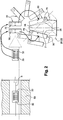
- a polyphase rotary electrical machine 1 forming, in the present exemplary embodiment of the invention, an alternator for a motor vehicle.
- the electric machine 1 can, if desired, be reversible and form an alternator-starter capable of operating in electric motor mode. to start the vehicle's combustion engine and in alternator mode to generate electrical energy.
- This machine 1 comprises a casing 10 and, inside the latter, a rotor 12 integral in rotation with a rotary shaft 14 of axis X, called the rotor shaft, and a stator 16 which surrounds the rotor 12.
- the stator 16 comprises a body 17 formed of a bundle of sheets provided with notches for mounting a stator winding 18 forming chignons on either side of the stator body 17.
- the rotor 12 comprises two pole wheels 20 and 22, each provided with a transverse flange 24 on the periphery of which are connected a plurality of claws 26 extending substantially in the axial direction A.
- Each of the claws 26 has an overall trapezoidal shape when observed in a radial direction R, as can be seen in the figure. figure 2 especially.
- the claws 26 of a pole wheel form with the claws 26 of the other pole wheel interpolar spaces 28 arranged to each receive a magnet structure 30.
- An excitation coil 34 is placed between the flanges 24 of the pole wheels 20 and 22.
- Each pole wheel 20; 22 has a bore forming an internal passage 38 for receiving the shaft 14.
- the pole wheels 20 and 22 are made for example of steel.
- the shaft 14 carries at its front end a pulley 40 belonging to a device for transmitting movement by means of at least one belt (not shown) between the alternator 1 and the combustion engine of the motor vehicle, and to its rear end of slip rings 42 connected by wire links (not shown) to the excitation winding 34 of rotor 12.
- Brushes of a brush holder 44 shown very schematically are arranged so as to rub on the slip rings, in order to supply the winding 34 with electric current.
- the inductor rotor 12 creates an induced alternating current in the stator 16.
- the housing 10 comprises, in the example considered, two parts, namely a front bearing 46 and a rear bearing 48 carrying the brush holder 44.
- the bearings 46 and 48 each carry a ball bearing 50 and 52 respectively for the rotational mounting of the shaft 14.
- the alternator 1 also comprises means for its cooling.
- the bearings 46 and 48 are perforated to allow cooling of the alternator by air circulation.
- the rotor 12 carries, in the example described, at least at one of its axial ends a fan intended to provide air circulation.
- a first ventilation element 54 is for example provided on the front transverse face of the rotor 12 and a second ventilation element 56 is provided on the rear face of the rotor 12.
- Each ventilation element 54 and 56 is provided with a plurality of blades. 58 and 60.
- each pole wheel 20; 22 has six claws 26 so as to define a rotor with 12 interpolar spaces 28.
- rotor 12 may have 2, 4, 6, 8 or 10 interpolar spaces 28, depending on the type of electrical machine desired.
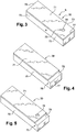
- Each magnet structure 30 comprises a permanent magnet 70, for example of rare earth, and a plate 71 made of non-magnetic material, for example of composite material containing glass fibers.
- the permanent magnet 70 has a substantially rectangular parallelepiped shape.
- This shape of the magnet exhibits invariance by rotating through an angle of 180 ° so that it is impossible to visually distinguish a side face 72 of North polarity and an opposite side face 73 of South polarity, after the magnet 70 has taken its magnetization.
- the magnet structures 30 are passed through a magnetization device 80 arranged to magnetize the magnets 70 of the structures 30 using a magnetic field represented by an arrow B.
- each magnet 70 has North and South polarities respectively on its opposite faces 72 and 73.
- the magnet structures 30 pass through device 80 through Iot, being aligned in parallel.
- the plate 71 has a rectangular shape and entirely covers one face of the permanent magnet 70, this plate 71 being fixed on the magnet 70 before passing through the magnetization device 80.
- each magnet structure 30 comprises an indexing mark 75 .
- the indexing mark 75 comprises an orifice 76 formed in the plate 71, closer to an axial end 77 than to the other end 78.
- first magnet structure 30 For a first magnet structure 30 to be deposited in a first interpolar space 28, the latter is oriented so that the index mark 75 is radially interior, and, for a second magnet structure 30 to be deposited in a second interpolar space 28, this structure 30 is rotated to place it with the indexing mark located on the outside (see figure 2 ).
- the invention thus makes it possible to avoid errors in the orientation of the magnetization of the structures 30, which is particularly advantageous when these structures 30 are put in place manually, the operator using the mark of. magnetization to orient the structures 30.
- magnet structures 30 are fixed on one of the pole wheels 20; 22 before assembly of this wheel with the other pole wheel.
- magnet structures 30 are secured to the pole wheel by magnetization, before being clamped between the two pole wheels 20 and 22.
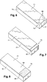
- the plate 71 entirely covers one face of the magnet 70.
- the magnet 70 has an excess length 78 relative to the wafer 71 in the longitudinal direction, on an axial end 77.
- This excess length thus forms an indexing mark 75 within the meaning of the invention, serving to identify a direction of orientation of the magnetization of the magnet structure 30.
- the plate 71 can thus be solid, without an orifice, which makes it possible in particular to simplify its manufacture in terms of cutting operations.
- the magnet structure 30 has in addition to the over-length 78, an orifice 76 in order to distinguish the sides of the structure 30 in a redundant manner.
- the wafer 71 has a length equal to that of the magnet 70, with cutouts 85 on an axial side so as to form an index mark 75.
- cutouts make it possible to quickly verify, with the naked eye, whether the magnet structures are arranged correctly in the interpolar spaces.
- cutouts 85 have for example a triangular shape.
- cutouts can have any other suitable shape.
- the wafer 71 may have a single rounded cutout formed on the middle of an edge of the wafer 71.
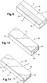
- the plate 71 comprises a portion of reduced thickness 87, extending on an axial side of the magnet 70.
- This portion 87 forms an indexing mark 75 within the meaning of the invention.
- the indexing mark 75 is formed by the shapes and / or dimensions of the plate 71.
- the indexing mark is formed by other means.
- the indexing mark 75 is formed by at least two zones having different optical properties, being in particular of different colors or reflecting properties
- the plate 71 comprises two zones 88 and 89, for example rectangular, of different areas, and having different colors.
- These zones 88 and 89 extend along a width of the magnet structure.
- the zones 88 and 89 of identical surface area extend along a length of the structure.
- the North side (N) can be associated with a first color of zone 89 and the South side (S) with a second color, different from the first color, of zone 88.
- the index mark 75 can, if desired, be formed on the magnet 70, and not on the wafer 71.
- the magnet structure 30 of the figure 10 is an unclaimed example of an index mark comprising a magnet 70 and a plate 71 entirely covering one face of this magnet 70.
- An index mark 75 is made on an axial end face 91 in the form of a notch 90.
- This notch 90 has for example a rectilinear shape.
- any other suitable shape of the notch 90 can be envisaged.
- the notch can be circular.
- the magnet 70 may have a shape with, symmetrically on its two opposite axial ends, rounded corners.
- the wafer 71 can, if desired, cover at least two faces of the magnet 70.
- the plate 71 has a portion 95 bent at right angles and covering a radial face of the permanent magnet 70. This face may be a front or rear face of the magnet.
- This portion 95 is used to define an indexing mark 75 not claimed within the meaning of the invention.
Landscapes
- Engineering & Computer Science (AREA)
- Power Engineering (AREA)
- Permanent Field Magnets Of Synchronous Machinery (AREA)
- Manufacture Of Motors, Generators (AREA)
Claims (8)
- Rotor (12) einer drehenden elektrischen Maschine, insbesondere eines Wechselstromgenerators eines Kraftfahrzeugs, der Folgendes umfasst:- zwei Polräder (20, 22), die jeweils mit einem quer verlaufenden Flansch (24) versehen sind, an dessen Umfang sich eine Vielzahl von Klauenpolen (26) anschließen, die sich im Wesentlichen gemäß einer Richtung (A) erstrecken, wobei die Klauenpole eines Polrades mit den Klauenpolen des anderen Polrades Pollücken (28) bilden, und- eine Vielzahl von Magnetstrukturen (30), die in den Pollücken (28) montiert sind, wobei die Pollücken so eingerichtet sind, dass sie jeweils eine Magnetstruktur (30) aufnehmen;wobei der Rotor dadurch gekennzeichnet ist, dass jede Magnetstruktur (30) mindestens eine Indexierungsmarkierung (75) umfasst, die eingerichtet ist, um ein visuelles Erkennen der Magnetisierungsrichtung dieser Magnetstruktur mit dem bloßen Auge zu ermöglichen und um ein schnelles Überprüfen, ob die Magnetstrukturen korrekt in den Pollücken (28) angeordnet sind, zu ermöglichen, wobei alle Magnetstrukturen (30) mit Bezug auf die Indexierungsmarkierung (75) eine gleiche Magnetisierungsrichtung aufweisen, und dadurch, dass jede Magnetstruktur (30) ein Plättchen (71) und einen an dem Plättchen angeordneten Magneten (70) umfasst, wobei die Indexierungsmarkierung (75) mindestens teilweise an dem Plättchen implementiert ist.
- Rotor nach dem vorhergehenden Anspruch, dadurch gekennzeichnet, dass die Indexierungsmarkierung (75) mindestens eine in dem Plättchen (71) gebildete Öffnung (76) umfasst.
- Rotor nach einem der vorhergehenden Ansprüche, dadurch gekennzeichnet, dass die Indexierungsmarkierung (75) in der Verlängerung der Länge des Plättchens eine Überlänge (78) des Magneten umfasst.
- Rotor nach Anspruch 1, dadurch gekennzeichnet, dass die Indexierungsmarkierung (75) durch eine Variation der Dicke des Plättchens (71) oder des Dauermagneten (70) gebildet ist.
- Rotor nach Anspruch 1, dadurch gekennzeichnet, dass die Indexierungsmarkierung (75) durch mindestens zwei Bereiche (88, 89) gebildet ist, die unterschiedliche optische Eigenschaften aufweisen, insbesondere von unterschiedlicher Farbe sind.
- Rotor nach einem der vorhergehenden Ansprüche, dadurch gekennzeichnet, dass die Magnetstrukturen eine im Wesentlichen rechteckige, parallelepipedische Form aufweisen.
- Rotor nach einem der vorhergehenden Ansprüche, dadurch gekennzeichnet, dass alle Magnetstrukturen identisch sind.
- Drehende elektrische Maschine, insbesondere ein Wechselstromgenerator (1) eines Kraftfahrzeugs, die einen Rotor nach einem der vorhergehenden Ansprüche umfasst.
Applications Claiming Priority (2)
| Application Number | Priority Date | Filing Date | Title |
|---|---|---|---|
| FR0759297A FR2924284A1 (fr) | 2007-11-26 | 2007-11-26 | Procede de fabrication d'un rotor de machine electrique tournante, notamment un alternateur |
| PCT/FR2008/052115 WO2009071827A2 (fr) | 2007-11-26 | 2008-11-24 | Procede de fabrication d'un rotor de machine electrique tournante, notamment un alternateur |
Publications (2)
| Publication Number | Publication Date |
|---|---|
| EP2218158A2 EP2218158A2 (de) | 2010-08-18 |
| EP2218158B1 true EP2218158B1 (de) | 2020-12-09 |
Family
ID=39666102
Family Applications (1)
| Application Number | Title | Priority Date | Filing Date |
|---|---|---|---|
| EP08857174.0A Active EP2218158B1 (de) | 2007-11-26 | 2008-11-24 | Rotoranordnung für eine elektrische maschine klauenpole und magnetstrukturen in den polenluecken aufweisend |
Country Status (7)
| Country | Link |
|---|---|
| US (1) | US8531081B2 (de) |
| EP (1) | EP2218158B1 (de) |
| KR (1) | KR20100095538A (de) |
| CN (1) | CN101874334B (de) |
| BR (1) | BRPI0817900B8 (de) |
| FR (1) | FR2924284A1 (de) |
| WO (1) | WO2009071827A2 (de) |
Families Citing this family (1)
| Publication number | Priority date | Publication date | Assignee | Title |
|---|---|---|---|---|
| CN103066772B (zh) * | 2012-12-26 | 2015-04-01 | 南车株洲电机有限公司 | 一种永磁电机磁钢装配工装 |
Family Cites Families (16)
| Publication number | Priority date | Publication date | Assignee | Title |
|---|---|---|---|---|
| USRE24943E (en) * | 1961-02-28 | Electrically controlled magnetic movement | ||
| US2836773A (en) * | 1955-04-29 | 1958-05-27 | Allard Instr Corp | Electrically controlled magnetic movement |
| US5858158A (en) * | 1992-03-11 | 1999-01-12 | Mark Iv Industries Limited | Electromagnetic disk and method of making |
| JP3646446B2 (ja) * | 1997-01-14 | 2005-05-11 | 株式会社デンソー | ランデルコア型回転電機 |
| JP3541920B2 (ja) * | 1997-10-27 | 2004-07-14 | 三菱電機株式会社 | 回転電機の回転子およびその製造方法 |
| JP3767136B2 (ja) * | 1997-11-13 | 2006-04-19 | 三菱電機株式会社 | 回転電機の回転子及びその製造方法 |
| FR2786625B1 (fr) * | 1998-11-30 | 2001-02-16 | Valeo Equip Electr Moteur | Alternateur de vehicule automobile a aimants interpolaires |
| FR2793085B1 (fr) * | 1999-04-30 | 2001-07-13 | Valeo Equip Electr Moteur | Alternateur pour vehicule automobile a aimants interpolaires |
| DE19951115A1 (de) * | 1999-10-23 | 2001-05-03 | Bosch Gmbh Robert | Elektrische Maschine |
| DE10153578B4 (de) * | 2000-11-06 | 2012-01-26 | Denso Corporation | Wechselstromgenerator für Fahrzeuge mit Permanentmagneten im Rotor und Verfahren zur Herstellung desselben |
| US6452301B1 (en) * | 2001-11-02 | 2002-09-17 | Electric Boat Corporation | Magnet retention arrangement for high speed rotors |
| JP3789361B2 (ja) * | 2002-01-18 | 2006-06-21 | 株式会社デンソー | 交流発電機 |
| JP3882725B2 (ja) * | 2002-03-12 | 2007-02-21 | 株式会社デンソー | 車両用回転電機 |
| JP4396471B2 (ja) * | 2004-10-01 | 2010-01-13 | 株式会社デンソー | 車両用回転電機およびその製造方法 |
| JP4735980B2 (ja) * | 2006-08-23 | 2011-07-27 | 株式会社デンソー | 車両用交流発電機及びその製造方法 |
| FR2906942B1 (fr) * | 2006-10-10 | 2014-07-04 | Valeo Equip Electr Moteur | Rotor a griffes muni d'elements ferromagnetiques interpolaires de largeur optimisee et machine tournante equipe d'un tel rotor |
-
2007
- 2007-11-26 FR FR0759297A patent/FR2924284A1/fr not_active Ceased
-
2008
- 2008-11-24 WO PCT/FR2008/052115 patent/WO2009071827A2/fr not_active Ceased
- 2008-11-24 US US12/743,888 patent/US8531081B2/en active Active
- 2008-11-24 EP EP08857174.0A patent/EP2218158B1/de active Active
- 2008-11-24 BR BRPI0817900A patent/BRPI0817900B8/pt active IP Right Grant
- 2008-11-24 KR KR1020107011391A patent/KR20100095538A/ko not_active Withdrawn
- 2008-11-24 CN CN2008801179045A patent/CN101874334B/zh active Active
Non-Patent Citations (1)
| Title |
|---|
| None * |
Also Published As
| Publication number | Publication date |
|---|---|
| FR2924284A1 (fr) | 2009-05-29 |
| CN101874334A (zh) | 2010-10-27 |
| CN101874334B (zh) | 2013-03-27 |
| WO2009071827A2 (fr) | 2009-06-11 |
| EP2218158A2 (de) | 2010-08-18 |
| BRPI0817900B8 (pt) | 2024-02-20 |
| BRPI0817900B1 (pt) | 2023-12-26 |
| KR20100095538A (ko) | 2010-08-31 |
| US8531081B2 (en) | 2013-09-10 |
| BRPI0817900A2 (pt) | 2015-03-31 |
| US20100295400A1 (en) | 2010-11-25 |
| WO2009071827A3 (fr) | 2009-10-08 |
Similar Documents
| Publication | Publication Date | Title |
|---|---|---|
| EP3602740B1 (de) | Motor oder elektromagnetischer generator mit einem rotor mit magnetisierten strukturen mit einheitsmagneten und einem stator mit konzentrischen wicklungen | |
| EP1362407B1 (de) | Verbesserte rotationsmaschine für automobile fahrzeuge | |
| FR2884367A1 (fr) | Cible appartenant a des moyens de suivi de la position d'un rotor d'une machine electrique tournante et machine electrique tournante comportant une telle cible | |
| EP2878071B1 (de) | Wicklung für ein statorelement eines permanentmagnetmotors oder generators mit mindestens einem einkomponentigen starren glied und herstellungsverfahren dafür | |
| WO2008074954A1 (fr) | Machine electrique tournante, en particulier pour un demarreur de vehicule automobile | |
| FR2920259A1 (fr) | Machine electrique tournante, en particulier pour un demarreur automobile | |
| EP2218158B1 (de) | Rotoranordnung für eine elektrische maschine klauenpole und magnetstrukturen in den polenluecken aufweisend | |
| EP3840182A1 (de) | Elektrisch umlaufende maschine mit einem abmessungsverhältnis, das geräusche minimiert | |
| EP2145376B1 (de) | Verfahren zur herstellung eines rotors für eine rotierende elektrische maschine, insbesondere einen generator | |
| EP1351367A1 (de) | Elektrische Maschine mit modularem Stator und/oder Rotor sowie Kraftfahrzeug-Kühler unter Verwendung einer solchen Maschine | |
| EP4111574B1 (de) | Rotor für einen elektromotor ausgestattet mit permanentmagneten aus kunststoffmaterial | |
| FR3079686A1 (fr) | Rotor de machine electrique tournante muni de languettes de maintien d'aimants permanents | |
| WO2018158517A1 (fr) | Rotor de machine électrique tournante munie d'au moins un roulement à ventilateur intégré | |
| FR3033959A1 (fr) | Rotor de machine electrique tournante a configuration d'aimants permanents optimisee | |
| EP4104276A1 (de) | Rotor für einen elektromotor mit sensoren | |
| EP4122082B1 (de) | Baugruppe bestehend aus einer rotierenden elektrischen maschine, einem elektronikmodul und einem verbinder | |
| FR3098047A1 (fr) | Piece bobinee pour une machine electrique tournante destinee a un vehicule automobile | |
| EP0762601A1 (de) | Verbesserter Wechselstromgeneratorlaüfer, insbesondere für Kraftwagen | |
| FR2837632A1 (fr) | Machine electrique a dent distincte de support d'un enroulement et vehicule automobile correspondant | |
| WO2019020490A1 (fr) | Rotor de machine électrique tournante muni d'une couche de résine dans les cavités d'aimants permanents | |
| WO2026017765A1 (fr) | Rotor pour moteur électrique équipé de flasques d'extrémité intégrant des plasto-aimants | |
| EP3053789B1 (de) | Antriebsrad und entsprechendes antriebssystem | |
| FR3053178A1 (fr) | Machine electrique tournante a rotor mono-levre | |
| WO2023166443A1 (fr) | Moteur électromagnétique à concentration de flux magnetiques | |
| FR3162326A1 (fr) | Rotor à aimants permanents |
Legal Events
| Date | Code | Title | Description |
|---|---|---|---|
| PUAI | Public reference made under article 153(3) epc to a published international application that has entered the european phase |
Free format text: ORIGINAL CODE: 0009012 |
|
| 17P | Request for examination filed |
Effective date: 20100603 |
|
| AK | Designated contracting states |
Kind code of ref document: A2 Designated state(s): AT BE BG CH CY CZ DE DK EE ES FI FR GB GR HR HU IE IS IT LI LT LU LV MC MT NL NO PL PT RO SE SI SK TR |
|
| AX | Request for extension of the european patent |
Extension state: AL BA MK RS |
|
| RIN1 | Information on inventor provided before grant (corrected) |
Inventor name: PFLEGER, ALEXANDRE Inventor name: BILTERYST, PIERRE-YVES Inventor name: GAS, OLIVIER |
|
| DAX | Request for extension of the european patent (deleted) | ||
| STAA | Information on the status of an ep patent application or granted ep patent |
Free format text: STATUS: EXAMINATION IS IN PROGRESS |
|
| 17Q | First examination report despatched |
Effective date: 20180313 |
|
| REG | Reference to a national code |
Ref country code: DE Ref legal event code: R079 Ref document number: 602008063559 Country of ref document: DE Free format text: PREVIOUS MAIN CLASS: H02K0001220000 Ipc: H02K0021040000 |
|
| GRAP | Despatch of communication of intention to grant a patent |
Free format text: ORIGINAL CODE: EPIDOSNIGR1 |
|
| STAA | Information on the status of an ep patent application or granted ep patent |
Free format text: STATUS: GRANT OF PATENT IS INTENDED |
|
| RIC1 | Information provided on ipc code assigned before grant |
Ipc: H02K 1/22 20060101ALI20200615BHEP Ipc: H02K 21/04 20060101AFI20200615BHEP |
|
| INTG | Intention to grant announced |
Effective date: 20200629 |
|
| GRAS | Grant fee paid |
Free format text: ORIGINAL CODE: EPIDOSNIGR3 |
|
| GRAA | (expected) grant |
Free format text: ORIGINAL CODE: 0009210 |
|
| STAA | Information on the status of an ep patent application or granted ep patent |
Free format text: STATUS: THE PATENT HAS BEEN GRANTED |
|
| AK | Designated contracting states |
Kind code of ref document: B1 Designated state(s): AT BE BG CH CY CZ DE DK EE ES FI FR GB GR HR HU IE IS IT LI LT LU LV MC MT NL NO PL PT RO SE SI SK TR |
|
| REG | Reference to a national code |
Ref country code: GB Ref legal event code: FG4D Free format text: NOT ENGLISH |
|
| REG | Reference to a national code |
Ref country code: AT Ref legal event code: REF Ref document number: 1344396 Country of ref document: AT Kind code of ref document: T Effective date: 20201215 Ref country code: CH Ref legal event code: EP |
|
| REG | Reference to a national code |
Ref country code: DE Ref legal event code: R096 Ref document number: 602008063559 Country of ref document: DE |
|
| REG | Reference to a national code |
Ref country code: IE Ref legal event code: FG4D Free format text: LANGUAGE OF EP DOCUMENT: FRENCH |
|
| PG25 | Lapsed in a contracting state [announced via postgrant information from national office to epo] |
Ref country code: FI Free format text: LAPSE BECAUSE OF FAILURE TO SUBMIT A TRANSLATION OF THE DESCRIPTION OR TO PAY THE FEE WITHIN THE PRESCRIBED TIME-LIMIT Effective date: 20201209 Ref country code: NO Free format text: LAPSE BECAUSE OF FAILURE TO SUBMIT A TRANSLATION OF THE DESCRIPTION OR TO PAY THE FEE WITHIN THE PRESCRIBED TIME-LIMIT Effective date: 20210309 Ref country code: GR Free format text: LAPSE BECAUSE OF FAILURE TO SUBMIT A TRANSLATION OF THE DESCRIPTION OR TO PAY THE FEE WITHIN THE PRESCRIBED TIME-LIMIT Effective date: 20210310 |
|
| REG | Reference to a national code |
Ref country code: AT Ref legal event code: MK05 Ref document number: 1344396 Country of ref document: AT Kind code of ref document: T Effective date: 20201209 |
|
| PG25 | Lapsed in a contracting state [announced via postgrant information from national office to epo] |
Ref country code: SE Free format text: LAPSE BECAUSE OF FAILURE TO SUBMIT A TRANSLATION OF THE DESCRIPTION OR TO PAY THE FEE WITHIN THE PRESCRIBED TIME-LIMIT Effective date: 20201209 Ref country code: LV Free format text: LAPSE BECAUSE OF FAILURE TO SUBMIT A TRANSLATION OF THE DESCRIPTION OR TO PAY THE FEE WITHIN THE PRESCRIBED TIME-LIMIT Effective date: 20201209 Ref country code: BG Free format text: LAPSE BECAUSE OF FAILURE TO SUBMIT A TRANSLATION OF THE DESCRIPTION OR TO PAY THE FEE WITHIN THE PRESCRIBED TIME-LIMIT Effective date: 20210309 |
|
| REG | Reference to a national code |
Ref country code: NL Ref legal event code: MP Effective date: 20201209 |
|
| PG25 | Lapsed in a contracting state [announced via postgrant information from national office to epo] |
Ref country code: HR Free format text: LAPSE BECAUSE OF FAILURE TO SUBMIT A TRANSLATION OF THE DESCRIPTION OR TO PAY THE FEE WITHIN THE PRESCRIBED TIME-LIMIT Effective date: 20201209 Ref country code: NL Free format text: LAPSE BECAUSE OF FAILURE TO SUBMIT A TRANSLATION OF THE DESCRIPTION OR TO PAY THE FEE WITHIN THE PRESCRIBED TIME-LIMIT Effective date: 20201209 |
|
| REG | Reference to a national code |
Ref country code: LT Ref legal event code: MG9D |
|
| PG25 | Lapsed in a contracting state [announced via postgrant information from national office to epo] |
Ref country code: CZ Free format text: LAPSE BECAUSE OF FAILURE TO SUBMIT A TRANSLATION OF THE DESCRIPTION OR TO PAY THE FEE WITHIN THE PRESCRIBED TIME-LIMIT Effective date: 20201209 Ref country code: EE Free format text: LAPSE BECAUSE OF FAILURE TO SUBMIT A TRANSLATION OF THE DESCRIPTION OR TO PAY THE FEE WITHIN THE PRESCRIBED TIME-LIMIT Effective date: 20201209 Ref country code: SK Free format text: LAPSE BECAUSE OF FAILURE TO SUBMIT A TRANSLATION OF THE DESCRIPTION OR TO PAY THE FEE WITHIN THE PRESCRIBED TIME-LIMIT Effective date: 20201209 Ref country code: RO Free format text: LAPSE BECAUSE OF FAILURE TO SUBMIT A TRANSLATION OF THE DESCRIPTION OR TO PAY THE FEE WITHIN THE PRESCRIBED TIME-LIMIT Effective date: 20201209 Ref country code: PT Free format text: LAPSE BECAUSE OF FAILURE TO SUBMIT A TRANSLATION OF THE DESCRIPTION OR TO PAY THE FEE WITHIN THE PRESCRIBED TIME-LIMIT Effective date: 20210409 Ref country code: LT Free format text: LAPSE BECAUSE OF FAILURE TO SUBMIT A TRANSLATION OF THE DESCRIPTION OR TO PAY THE FEE WITHIN THE PRESCRIBED TIME-LIMIT Effective date: 20201209 |
|
| PG25 | Lapsed in a contracting state [announced via postgrant information from national office to epo] |
Ref country code: AT Free format text: LAPSE BECAUSE OF FAILURE TO SUBMIT A TRANSLATION OF THE DESCRIPTION OR TO PAY THE FEE WITHIN THE PRESCRIBED TIME-LIMIT Effective date: 20201209 Ref country code: PL Free format text: LAPSE BECAUSE OF FAILURE TO SUBMIT A TRANSLATION OF THE DESCRIPTION OR TO PAY THE FEE WITHIN THE PRESCRIBED TIME-LIMIT Effective date: 20201209 |
|
| REG | Reference to a national code |
Ref country code: DE Ref legal event code: R097 Ref document number: 602008063559 Country of ref document: DE |
|
| PG25 | Lapsed in a contracting state [announced via postgrant information from national office to epo] |
Ref country code: IS Free format text: LAPSE BECAUSE OF FAILURE TO SUBMIT A TRANSLATION OF THE DESCRIPTION OR TO PAY THE FEE WITHIN THE PRESCRIBED TIME-LIMIT Effective date: 20210409 |
|
| PLBE | No opposition filed within time limit |
Free format text: ORIGINAL CODE: 0009261 |
|
| STAA | Information on the status of an ep patent application or granted ep patent |
Free format text: STATUS: NO OPPOSITION FILED WITHIN TIME LIMIT |
|
| PG25 | Lapsed in a contracting state [announced via postgrant information from national office to epo] |
Ref country code: IT Free format text: LAPSE BECAUSE OF FAILURE TO SUBMIT A TRANSLATION OF THE DESCRIPTION OR TO PAY THE FEE WITHIN THE PRESCRIBED TIME-LIMIT Effective date: 20201209 |
|
| 26N | No opposition filed |
Effective date: 20210910 |
|
| PG25 | Lapsed in a contracting state [announced via postgrant information from national office to epo] |
Ref country code: SI Free format text: LAPSE BECAUSE OF FAILURE TO SUBMIT A TRANSLATION OF THE DESCRIPTION OR TO PAY THE FEE WITHIN THE PRESCRIBED TIME-LIMIT Effective date: 20201209 Ref country code: ES Free format text: LAPSE BECAUSE OF FAILURE TO SUBMIT A TRANSLATION OF THE DESCRIPTION OR TO PAY THE FEE WITHIN THE PRESCRIBED TIME-LIMIT Effective date: 20201209 Ref country code: DK Free format text: LAPSE BECAUSE OF FAILURE TO SUBMIT A TRANSLATION OF THE DESCRIPTION OR TO PAY THE FEE WITHIN THE PRESCRIBED TIME-LIMIT Effective date: 20201209 |
|
| PG25 | Lapsed in a contracting state [announced via postgrant information from national office to epo] |
Ref country code: IS Free format text: LAPSE BECAUSE OF FAILURE TO SUBMIT A TRANSLATION OF THE DESCRIPTION OR TO PAY THE FEE WITHIN THE PRESCRIBED TIME-LIMIT Effective date: 20210409 |
|
| PG25 | Lapsed in a contracting state [announced via postgrant information from national office to epo] |
Ref country code: MC Free format text: LAPSE BECAUSE OF FAILURE TO SUBMIT A TRANSLATION OF THE DESCRIPTION OR TO PAY THE FEE WITHIN THE PRESCRIBED TIME-LIMIT Effective date: 20201209 |
|
| REG | Reference to a national code |
Ref country code: CH Ref legal event code: PL |
|
| GBPC | Gb: european patent ceased through non-payment of renewal fee |
Effective date: 20211124 |
|
| PG25 | Lapsed in a contracting state [announced via postgrant information from national office to epo] |
Ref country code: LU Free format text: LAPSE BECAUSE OF NON-PAYMENT OF DUE FEES Effective date: 20211124 Ref country code: BE Free format text: LAPSE BECAUSE OF NON-PAYMENT OF DUE FEES Effective date: 20211130 |
|
| REG | Reference to a national code |
Ref country code: BE Ref legal event code: MM Effective date: 20211130 |
|
| PG25 | Lapsed in a contracting state [announced via postgrant information from national office to epo] |
Ref country code: LI Free format text: LAPSE BECAUSE OF NON-PAYMENT OF DUE FEES Effective date: 20211130 Ref country code: CH Free format text: LAPSE BECAUSE OF NON-PAYMENT OF DUE FEES Effective date: 20211130 |
|
| PG25 | Lapsed in a contracting state [announced via postgrant information from national office to epo] |
Ref country code: IE Free format text: LAPSE BECAUSE OF NON-PAYMENT OF DUE FEES Effective date: 20211124 Ref country code: GB Free format text: LAPSE BECAUSE OF NON-PAYMENT OF DUE FEES Effective date: 20211124 |
|
| PG25 | Lapsed in a contracting state [announced via postgrant information from national office to epo] |
Ref country code: HU Free format text: LAPSE BECAUSE OF FAILURE TO SUBMIT A TRANSLATION OF THE DESCRIPTION OR TO PAY THE FEE WITHIN THE PRESCRIBED TIME-LIMIT; INVALID AB INITIO Effective date: 20081124 Ref country code: CY Free format text: LAPSE BECAUSE OF FAILURE TO SUBMIT A TRANSLATION OF THE DESCRIPTION OR TO PAY THE FEE WITHIN THE PRESCRIBED TIME-LIMIT Effective date: 20201209 |
|
| P01 | Opt-out of the competence of the unified patent court (upc) registered |
Effective date: 20230528 |
|
| PG25 | Lapsed in a contracting state [announced via postgrant information from national office to epo] |
Ref country code: TR Free format text: LAPSE BECAUSE OF FAILURE TO SUBMIT A TRANSLATION OF THE DESCRIPTION OR TO PAY THE FEE WITHIN THE PRESCRIBED TIME-LIMIT Effective date: 20201209 |
|
| PG25 | Lapsed in a contracting state [announced via postgrant information from national office to epo] |
Ref country code: MT Free format text: LAPSE BECAUSE OF FAILURE TO SUBMIT A TRANSLATION OF THE DESCRIPTION OR TO PAY THE FEE WITHIN THE PRESCRIBED TIME-LIMIT Effective date: 20201209 |
|
| PGFP | Annual fee paid to national office [announced via postgrant information from national office to epo] |
Ref country code: DE Payment date: 20251117 Year of fee payment: 18 |
|
| PGFP | Annual fee paid to national office [announced via postgrant information from national office to epo] |
Ref country code: FR Payment date: 20251128 Year of fee payment: 18 |
|
| REG | Reference to a national code |
Ref country code: DE Ref legal event code: R081 Ref document number: 602008063559 Country of ref document: DE Owner name: VALEO ELECTRIFICATION, FR Free format text: FORMER OWNER: VALEO EQUIPEMENTS ELECTRIQUES MOTEUR, CRETEIL-CEDEX, FR |