EP2217317B1 - Hyperbaric wound treatment device - Google Patents
Hyperbaric wound treatment device Download PDFInfo
- Publication number
- EP2217317B1 EP2217317B1 EP08846367.4A EP08846367A EP2217317B1 EP 2217317 B1 EP2217317 B1 EP 2217317B1 EP 08846367 A EP08846367 A EP 08846367A EP 2217317 B1 EP2217317 B1 EP 2217317B1
- Authority
- EP
- European Patent Office
- Prior art keywords
- end cap
- housing
- wall
- cuff
- cam
- Prior art date
- Legal status (The legal status is an assumption and is not a legal conclusion. Google has not performed a legal analysis and makes no representation as to the accuracy of the status listed.)
- Active
Links
Images





Classifications
-
- A—HUMAN NECESSITIES
- A61—MEDICAL OR VETERINARY SCIENCE; HYGIENE
- A61G—TRANSPORT, PERSONAL CONVEYANCES, OR ACCOMMODATION SPECIALLY ADAPTED FOR PATIENTS OR DISABLED PERSONS; OPERATING TABLES OR CHAIRS; CHAIRS FOR DENTISTRY; FUNERAL DEVICES
- A61G10/00—Treatment rooms or enclosures for medical purposes
- A61G10/02—Treatment rooms or enclosures for medical purposes with artificial climate; with means to maintain a desired pressure, e.g. for germ-free rooms
- A61G10/023—Rooms for the treatment of patients at over- or under-pressure or at a variable pressure
- A61G10/026—Rooms for the treatment of patients at over- or under-pressure or at a variable pressure for hyperbaric oxygen therapy
-
- A—HUMAN NECESSITIES
- A61—MEDICAL OR VETERINARY SCIENCE; HYGIENE
- A61M—DEVICES FOR INTRODUCING MEDIA INTO, OR ONTO, THE BODY; DEVICES FOR TRANSDUCING BODY MEDIA OR FOR TAKING MEDIA FROM THE BODY; DEVICES FOR PRODUCING OR ENDING SLEEP OR STUPOR
- A61M35/00—Devices for applying media, e.g. remedies, on the human body
- A61M35/20—Non-portable devices, e.g. spraying booths
-
- A—HUMAN NECESSITIES
- A61—MEDICAL OR VETERINARY SCIENCE; HYGIENE
- A61M—DEVICES FOR INTRODUCING MEDIA INTO, OR ONTO, THE BODY; DEVICES FOR TRANSDUCING BODY MEDIA OR FOR TAKING MEDIA FROM THE BODY; DEVICES FOR PRODUCING OR ENDING SLEEP OR STUPOR
- A61M35/00—Devices for applying media, e.g. remedies, on the human body
- A61M35/30—Gas therapy for therapeutic treatment of the skin
-
- A—HUMAN NECESSITIES
- A61—MEDICAL OR VETERINARY SCIENCE; HYGIENE
- A61H—PHYSICAL THERAPY APPARATUS, e.g. DEVICES FOR LOCATING OR STIMULATING REFLEX POINTS IN THE BODY; ARTIFICIAL RESPIRATION; MASSAGE; BATHING DEVICES FOR SPECIAL THERAPEUTIC OR HYGIENIC PURPOSES OR SPECIFIC PARTS OF THE BODY
- A61H33/00—Bathing devices for special therapeutic or hygienic purposes
- A61H33/14—Devices for gas baths with ozone, hydrogen, or the like
- A61H2033/143—Devices for gas baths with ozone, hydrogen, or the like with oxygen
Definitions
- some re-usable wound treatment devices form seals about the limb of a patient using tape. Often, these tape seals leak and come undone, allowing valuable treatment gas to escape. Accordingly, a seal is desired that can effectively seal the device against the limb without the use of tape.
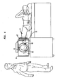
- FIG. 1 illustrates a patient receiving hyperbaric therapy on a limb such as the patient's leg.
- the limb is placed inside a hyperbaric wound treatment device 10 constructed according to an embodiment of the present invention.
- a hyperbaric wound treatment device 10 constructed according to an embodiment of the present invention.
- any type of wound treatment may be used such as compression therapy or negative pressure therapy and the like.
- first end cap 18 Mounted to one open end of housing 13 is a first end cap 18 that closes and seals the open end 14 of the housing.
- the first end cap 18 has a circular perimeter that generally matches the outer diameter of the cylindrical housing wall 13a and a lip 19 forming a cylindrical protrusion 25 that extends slightly into the open end 14 of the housing 13.
- the first end cap 18 can be releasably or fixedly secured to the housing by any suitable means and may include a gasket (not shown) located, about the lip 19. Permanent attachment may be achieved by gluing or heat welding, while releasable attachment may include the use of clamps (not shown) and the like. Further, the first end cap 18 can include a semi-spherical shaped body 18a that projects outwardly from the end cap.
- the semi-spherical shape of the body 18a is advantageous for withstanding the pressures within housing 13.
- the thickness at the center of the end cap 18 can be greater than the thickness of the housing wall 13a. This greater thickness is advantages for allowing the first end cap 18 to withstand the pressures within the housing 13.
- a second end cap 20 is similarly circular with an opening 21, optionally being a central opening sized to receive an appendage of a patient.
- outer tubular wall 28 includes a valve 24 which is in fluid communication with chamber 22c for inflating the cuff 22 with a gas, such as oxygen or air.
- a gas such as oxygen or air.
- inner wall 26 of the cuff 22 expands inwardly to form a seal, such as a hermetic seal depending upon the inflation pressure, against the limb disposed in passageway 34 of the cuff 22.
- Inner and outer tubular walls 26 and 28 may be joined and sealed together at their respective ends directly or indirectly by an interconnecting sidewall 30 to form chamber 22c, which can be inflated as described below.
- the cuff is preferably made from synthetic thermoplastic material which can be RF welded, thermal bonded or adhesive bonded.
- the cuff 22 has a length L, an inside diameter (ID) and an outside diameter (OD).
- the inside diameter (ID) is formed from the inside tubular wall 26 and the outside diameter (OD) is formed from the outside tubular wall 28.
- cuff 22 is inflated using valve 24, which opens and closes fluid communication between a pressurized fluid supply (not shown) and chamber 22c. Air or any suitable gas is introduced into chamber 22c through valve 24 between the inside and outside tubular walls 26 and 28 to thereby inflate the cuff 22.
- ID the inside diameter of the inner tubular wall
- X the inside diameter of the inner tubular wall
- the inner tubular wall 26 is compressed such that its inside diameter reduces to an inside diameter less than X. The inside diameter then decreases when inflated enough to snugly encircle and seal against the appendage or limb being treated, once the limb has been inserted.
- the skirt 40 includes an annular groove 44 that receives and is releasably engaged by lip 38.
- lip 38 of the frusto-conical member 226 is pulled over skirt 40 of end cap 20
- lip 38 is received into groove 44
- the frusto-conical member 22b wraps around the entire circumference of the groove 44 and annular skirt 40.
- the inner diameter of the frusto-conical member 22b may be smaller than the outside diameter of skirt 40 so that the frusto-conical member must be stretched to fit over the skirt 40 and thereby provide a compression fit with skirt 40.
- cuff 22 is mounted to the second end cap 20 before the second end cap is mounted to the open end 12 of the housing 13.
- the cuff 20 is received entirely within the internal chamber 13b.
- the orientation of the cuff 22 and second end cap 20 can be reversed such that the cuff can be wholly external to the housing 13 and still create a hermetic seal against the limb.
- the cuff 22 can be configured to be only partially received within the housing 13.
- housing 13 optionally includes one or more access ports 16.
- an extension 15 can be formed on a side of the housing 13 to forms the access port 16.
- Access port 16 includes an opening 45 in housing wall 13a and a removable cover 46 (See FIGS. 7 and 8 ).
- access port 16 is large enough to permit a clinician sufficient access to the appendage and, further, to the wound to provide medication for the wound or to change dressings.
- Cover 46 may be secured over opening 45 to close the access port 16 using a plurality of clamps 48, as shown in FIG. 7 .
- a lip 17 ( FIGS. 2 and 3 ) can be formed at the access port 16 to accommodate the cover 46.
- the cover 46 may be releasably coupled to the lip 17 using clamps as described below.
- Cover 46 may be formed from a suitable material, such as a polymer, including cast acrylic similar to housing wall 13a. Additionally, cover 46 may be transparent so as to provide visual access to the wound within housing 13. Although shown having a circular shape, the access port 16 can have any shape as desired such as square, oval, polygonal and the like.
- clamps 48 are constructed in a manner that can compensate for the natural deformity in the gaskets.
- cover 46 has a plurality of arcuate sides 50 each with a corresponding plurality of slots 52. Although three sides 50 and three slots 52 are illustrated herein, any numbers of sides and corresponding slots can be utilized.
- Each side 50 has a first diameter near an inside edge 54 of the respective side 50 and a second larger diameter near an outside edge 56 adjacent the slot 52 such that the sides flare radially outwardly with increasing diameter between the first and second diameters.
- the slots 52 are configured to mate with clamps 48 which are disposed on the lip 17.
- the number of slots 52 correspond to the number of clamps 48. It should be understood that the number of slots 52 or clamps 48 can be varied correspondingly,
- the cover 46 is placed over the opening 45 against the lip 17 and turned in a clockwise manner so that slots 52 of the cover mate with the clamps 48.
- the cover 46 can be easily configured so that turning it counter clockwise will be equally effective.
- the clamps 48 fasten the cover 46 to the lip 17, to be described more fully below.
- a gasket is placed between the cover 46 and the lip 17.
- FIGS. 10 and 11A illustrate details of the clamp mechanism where the clamp 48 includes a mounting stud 58, a swivel rod 60, which is internally threaded, an eccentric cam 62 having a flat surface 64, and a handle 66.
- Each mounting stud 58 is fastened at one end to the lip 17 of the access port 16.
- the other end of the stud 58 is threadably engaged within a threaded socket 60a formed in the swivel rod 60.
- handle 66 threads into a threaded socket 62a in cam 62.
- slots 52 of cover 46 are arranged so that they align with the mounting studs 58.
- Cover 46 is positioned in the space created around the mounting stud 58 between cam 62 and the lip 17.
- gasket 68 Positioned between the lip 17 and the cover 46 is a gasket 68.
- gasket 68 includes a hole (not shown) for fitting over the mounting stud 58.
- the cover 46 is placed over the access port 16, the cover's slots 52 mate with the mounting stud 58 of the clamp 48 and the handle 66 is rotated to close the clamp 48 and fasten the cover 46 to the lip 17.
- the handle 66 In a third position, depicted in FIG. 11C , the handle 66 is at an angle between 180° and 270° of the mounting stud 58. The cam 62 has compressed the gasket 68 to an even greater extent reducing gap A even further. Finally, as depicted in FIG. 11D , the handle 66 is rotated to be at an angle of 270° from the mounting stud 58. In this position, the flat surface 64 is parallel to and faces the gasket 68. At this last and locked position, cam 62 exerts the greatest compression force against gasket 68; gap is at or near zero. Thus, at various positions, the cam 62 accommodates changes in the thickness of the gasket 68, reducing the size of gap A.
- the open end 12 can include a lip 27 similar to lip 17 and have clamps 48 mounted thereon.
- the second end cap 20 can be configured in a manner similar to that of cover 46. Generally, the second end cap 20 can have arcuate sides 50 with slots 52 for mating with the clamps 48 disposed on the second end lip 27.
- the primary difference between the second end cap 20, in this embodiment and the cover 46 discussed earlier is that the second end cap 20 is open at the center 21 to accommodate the limb.
- a gasket (not shown) can be placed between the lip 27 and the second end cap 20.
- a hermetic seal between the housing and the second end cap 20 can be formed by the cuff 22 in the manner discussed previously.
Landscapes
- Health & Medical Sciences (AREA)
- Public Health (AREA)
- Life Sciences & Earth Sciences (AREA)
- Veterinary Medicine (AREA)
- General Health & Medical Sciences (AREA)
- Animal Behavior & Ethology (AREA)
- Hematology (AREA)
- Anesthesiology (AREA)
- Heart & Thoracic Surgery (AREA)
- Engineering & Computer Science (AREA)
- Biomedical Technology (AREA)
- Emergency Medicine (AREA)
- Pulmonology (AREA)
- Accommodation For Nursing Or Treatment Tables (AREA)
- Surgical Instruments (AREA)
Description
- Hyperbaric chambers are device which create sealed environments for the application of therapeutic gases to hasten healing of lesions or wounds on a patient's body. As described in
U.S. Patent No. 5,060,644 , entitled, "Hyperbaric Chamber Apparatus," the disclosure of which is incorporated herein by reference, the introduction of pressurized gas, such as oxygen into such an encapsulated environment promotes healing of various types of lesions and wounds. - When hyperbaric chambers were first introduced for healing of lesions or wounds, they encompassed the entire body. As time progressed, hyperbaric chambers became more sophisticated, and topical hyperbaric chambers were developed, as described in
U.S. Pat. No. 5,154,697 entitled, "Collapsible Topical Hyperbaric Apparatus" and4,801,291 , entitled, "Portable Topical Hyperbaric Apparatus," which are incorporated by reference herein. - The current re-usable wound treatment devices typically have rigid transparent panels affixed to a rigid frame. Seals placed between the panels and the frames have a tendency to leak with repeated use as the seals deform over time. Also, the panels have a tendency to loosen their seal due to the cyclical pressures in the device. Therefore, a re-usable wound treatment device is desired that can effectively and efficiently withstand the operational pressures, as well as provide an effective hermetic seal, even as the seals deform with use.
- Further, some re-usable wound treatment devices form seals about the limb of a patient using tape. Often, these tape seals leak and come undone, allowing valuable treatment gas to escape. Accordingly, a seal is desired that can effectively seal the device against the limb without the use of tape.
-
US 5,458,562 describes a circulation enhancing device in the form of an airtight boot contoured to the injured foot, a pulsed synchronized tourniquet for inhibiting blood flow to the injured foot during an over-pressure cycle and a controlled circuit which monitors the heart's systolic and diastolic pressure pulsations and provides electrical control signals to the pressure modulator to assure that the over-pressure and vacuum pulses are cyclic and in synchronism with the heart's systolic and diastolic pressure pulsations. The circulation enhancing boot comprises a pair of boot halves joined together by a hinge assembly located at the back of the boot. The boot has a pneumatic cuff attached to the inner surface at a top portion of the boot, which cuff may be inflated so that the cuff encircles the leg forming an airtight seal about the leg. -
WO 2006/091243 describes a hyperbaric oxygen device comprising an enclosure including a collapsible bag defined by two sheets of fluid-impervious material sealed together at both ends such that gas can be delivered between the sheets to inflate the enclosure to a rigid state and maintain the enclosure in the rigid state when oxygen pressure in the interior of the enclosure is cycled between ambient pressure and above ambient pressure. - The present invention is set out in the appended claims. Described herein is a wound treatment device which includes a rigid housing having a housing wall with a first end and a second end forming a chamber therebetween. The device can further include an inflatable cuff releasably coupled to the housing wall at the first end. The housing wall can include a sidewall having an opening, a cover for closing the opening, and a cam mechanism for releasably fastening the cover to the sidewall surrounding the opening. The cam mechanism can include a cam having a flat surface, a swivel rod disposed within the cam for coupling with the housing, and a handle for rotating the cam.
- Described herein is a wound treatment device which can include a rigid housing having a housing wall with a first end and a second end forming a chamber therebetween, an inflatable cuff releasably coupled to the housing wall at the first end, and an end cap coupled to the housing wall at the second end having a semispherical body extending out of the chamber.
- Described herein is a rigid wound treatment device which can include a cylindrical wall having spaced apart ends forming a chamber therebetween, and an inflatable cuff releasably coupled to one of the ends and extending in the chamber.
- The various objects, advantages and features of this invention will be more fully apparent from a reading of the following detailed description in conjunction with the accompanying drawings in which like reference numerals refer to like parts, and in which:
-
FIG. 1 is schematic illustration of a patient receiving wound treatment using a wound treatment device according to an embodiment of the present invention. -
FIG. 2 is a perspective view of a housing for the wound treatment device ofFIG. 1 . -
FIG. 3 is an exploded perspective view of the housing ofFIG. 2 . -
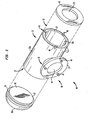
FIG. 4 is a perspective view of a cuff seal assembly. -
FIG. 5 is a side elevational view of the cuff seal assembly in an unassembled state. -
FIG. 6 is a side elevational view of the cuff seal assembly in an assembled state. -
FIG. 7 is an elevational view of an access port and cover of the device ofFIG. 1 , according to an embodiment of the present invention. -
FIG. 8 is an elevational view of the cover ofFIG. 7 . -
FIG. 9 is an elevational view of the access port ofFIG. 7 . -
FIG. 10 is a perspective exploded view of a clamp, in accordance with an embodiment of the present invention. -
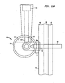
FIGS. 11A ,11B ,11C and11D are enlarged side elevational views of the clamp ofFIG. 10 , shown sealing the access port with the cover. -
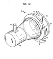
FIG. 12 is a perspective view of another embodiment of the present invention. -
FIG. 1 illustrates a patient receiving hyperbaric therapy on a limb such as the patient's leg. The limb is placed inside a hyperbaricwound treatment device 10 constructed according to an embodiment of the present invention. Although embodiments of the invention disclosed herein describe hyperbaric treatment, any type of wound treatment may be used such as compression therapy or negative pressure therapy and the like. - Referring more particularly to
FIGS. 2 and3 ,device 10 includes anelongated housing 13 havingopen ends Housing 13 is formed from a generallycontinuous housing wall 13a that defines aninternal chamber 13b having a generally cylindrical shape for evenly distributing the pressures that are employed during hyperbaric therapy.Housing wall 13a can be formed from a rigid polymeric material, such as cast acrylics or a like material capable of withstanding the pressures employed during treatment. Further,wall 13a can be transparent to allow visual access intochamber 13b. Optionally,housing 13 can include aside access port 16 through which a clinician can have access to the wound on the patient's limb. - Mounted to one open end of
housing 13 is afirst end cap 18 that closes and seals theopen end 14 of the housing. Thefirst end cap 18 has a circular perimeter that generally matches the outer diameter of thecylindrical housing wall 13a and alip 19 forming acylindrical protrusion 25 that extends slightly into theopen end 14 of thehousing 13. Thefirst end cap 18 can be releasably or fixedly secured to the housing by any suitable means and may include a gasket (not shown) located, about thelip 19. Permanent attachment may be achieved by gluing or heat welding, while releasable attachment may include the use of clamps (not shown) and the like. Further, thefirst end cap 18 can include a semi-sphericalshaped body 18a that projects outwardly from the end cap. The semi-spherical shape of thebody 18a is advantageous for withstanding the pressures withinhousing 13. Optionally, the thickness at the center of theend cap 18 can be greater than the thickness of thehousing wall 13a. This greater thickness is advantages for allowing thefirst end cap 18 to withstand the pressures within thehousing 13. In the illustrated embodiment, asecond end cap 20 is similarly circular with an opening 21, optionally being a central opening sized to receive an appendage of a patient. - As best seen in
FIGS. 5 and 6 , thesecond end cap 20 attaches to acuff seal assembly 23 to seal against the appendage. Thecuff seal assembly 23 includes acuff 22 removably attached to thesecond end cap 20 by a connectingmember 22b.Cuff 22 and connectingmember 22b are located and mounted insidechamber 13b by means of thesecond end cap 20.Cuff 22 is formed from a generally cylindrical shapedtubular member 22a, as shown inFIG. 4 , having inner and outer concentrictubular walls cuff 22 has a firstopen end 32 for receiving a limb inpassageway 34 formed by thetubular member 22a. Thetubular member 22a is coupled to thesecond end cap 20 by a connectingmember 22b in the form of a frusto-conical sleeve. - The inner and outer
tubular walls cuff 22 are sealed together to form aninflatable chamber 22c therebetween as shown inFIG. 4 . To inflatecuff 22, outertubular wall 28 includes avalve 24 which is in fluid communication withchamber 22c for inflating thecuff 22 with a gas, such as oxygen or air. Upon inflation,inner wall 26 of thecuff 22 expands inwardly to form a seal, such as a hermetic seal depending upon the inflation pressure, against the limb disposed inpassageway 34 of thecuff 22. - Inner and outer
tubular walls sidewall 30 to formchamber 22c, which can be inflated as described below. The cuff is preferably made from synthetic thermoplastic material which can be RF welded, thermal bonded or adhesive bonded. Thecuff 22 has a length L, an inside diameter (ID) and an outside diameter (OD). The inside diameter (ID) is formed from the insidetubular wall 26 and the outside diameter (OD) is formed from theoutside tubular wall 28. - As noted above,
cuff 22 is inflated usingvalve 24, which opens and closes fluid communication between a pressurized fluid supply (not shown) andchamber 22c. Air or any suitable gas is introduced intochamber 22c throughvalve 24 between the inside and outsidetubular walls cuff 22. Prior to inflation, the inside diameter (ID) of the inner tubular wall is X. This ensures that thecuff 22 inner diameter is large enough to accommodate sliding a limb through thecuff 22, and hence reduce the trauma to the patient's appendage. Upon inflation, the innertubular wall 26 is compressed such that its inside diameter reduces to an inside diameter less than X. The inside diameter then decreases when inflated enough to snugly encircle and seal against the appendage or limb being treated, once the limb has been inserted. - In a further embodiment,
cuff 22 is formed from a flexible elastic material, such as a rubber or latex material, with anoutside tubular wall 28 and theside wall 30 having a thickness greater than the thickness of the insidetubular wall 26. This increase in thickness results in greater stiffness inwalls cuff 22 is inflated,walls tubular wall 26 expanding toward thepassageway 34 to accommodate the inflation pressure and, thus decreasing the inner diameter. Due to its reduced thickness, the insidetubular wall 26 will stretch where needed, to accommodate the surface topology of the limb or appendage while still sealing against the limb or appendage. By providing a relatively flexible inner tubular member,cuff 22 can seal against any variations in limb size or shape, such as a knee or ankle, along the length L of thecuff 22. - To couple the
open end 32 of thecuff 22 to thesecond end cap 20, the frusto-conical connectingmember 22b extending from the cuff is provided with alip 38 formed around its distal edge. The frusto-conical connectingmember 22b is similarly formed from a flexible elastic material, such as a rubber or latex material. Themember 22 may be integrally formed with a portion of thetubular member 22a, or joined thereto by any suitable means, such as RF welding, thermal bonding or glueing and the like.Lip 38 may be formed as an enlarged edge, such as a rolled edge of the frusto-conical member 22b, or as a thickened edge portion of the frusto-conical member. As understood fromFIGS. 5 and 6 ,lip 38 releasably engages thesecond end cap 20. To this end, thesecond end cap 20 may have an inwardly projectingannular skirt 40 that inserts into opening 21 ofend cap 20 or which is formed therewith. Further,end cap 20 includes agasket 42 for sealing, such as hermetically sealing, against thefirst end 12 of thehousing 13 whenend cap 20 is mounted to the housing. - The
skirt 40 includes anannular groove 44 that receives and is releasably engaged bylip 38. Thus, whenlip 38 of the frusto-conical member 226 is pulled overskirt 40 ofend cap 20,lip 38 is received intogroove 44, and the frusto-conical member 22b wraps around the entire circumference of thegroove 44 andannular skirt 40. Further, the inner diameter of the frusto-conical member 22b may be smaller than the outside diameter ofskirt 40 so that the frusto-conical member must be stretched to fit over theskirt 40 and thereby provide a compression fit withskirt 40. - Typically,
cuff 22 is mounted to thesecond end cap 20 before the second end cap is mounted to theopen end 12 of thehousing 13. Thus, whencuff 22 is mounted on thesecond end cap 20 and inserted intohousing 13, thecuff 20 is received entirely within theinternal chamber 13b. However, the orientation of thecuff 22 andsecond end cap 20 can be reversed such that the cuff can be wholly external to thehousing 13 and still create a hermetic seal against the limb. Further, thecuff 22 can be configured to be only partially received within thehousing 13. - As noted above,
housing 13 optionally includes one ormore access ports 16. As best seen inFIGS. 2 and3 , anextension 15 can be formed on a side of thehousing 13 to forms theaccess port 16.Access port 16 includes anopening 45 inhousing wall 13a and a removable cover 46 (SeeFIGS. 7 and8 ). Optionally,access port 16 is large enough to permit a clinician sufficient access to the appendage and, further, to the wound to provide medication for the wound or to change dressings.Cover 46 may be secured overopening 45 to close theaccess port 16 using a plurality ofclamps 48, as shown inFIG. 7 . A lip 17 (FIGS. 2 and3 ) can be formed at theaccess port 16 to accommodate thecover 46. Thus, thecover 46 may be releasably coupled to thelip 17 using clamps as described below. -
Cover 46 may be formed from a suitable material, such as a polymer, including cast acrylic similar tohousing wall 13a. Additionally, cover 46 may be transparent so as to provide visual access to the wound withinhousing 13. Although shown having a circular shape, theaccess port 16 can have any shape as desired such as square, oval, polygonal and the like. - There may be a flexible, polymer gasket or a seal between the
cover 46 and thelip 17 to provide a seal, such as a hermetic seal, around opening 45. This gasket prevents or reduces treatment gas from escaping. Due to their inherent nature, gaskets can deform over time, permitting valuable treatment gas to escape. Therefore, in an embodiment of the present invention, clamps 48 are constructed in a manner that can compensate for the natural deformity in the gaskets. - Referring to
FIGS. 7-9 , cover 46 has a plurality ofarcuate sides 50 each with a corresponding plurality ofslots 52. Although threesides 50 and threeslots 52 are illustrated herein, any numbers of sides and corresponding slots can be utilized. Eachside 50 has a first diameter near aninside edge 54 of therespective side 50 and a second larger diameter near anoutside edge 56 adjacent theslot 52 such that the sides flare radially outwardly with increasing diameter between the first and second diameters. - The
slots 52 are configured to mate withclamps 48 which are disposed on thelip 17. The number ofslots 52 correspond to the number ofclamps 48. It should be understood that the number ofslots 52 or clamps 48 can be varied correspondingly, Thecover 46 is placed over theopening 45 against thelip 17 and turned in a clockwise manner so thatslots 52 of the cover mate with theclamps 48. Thecover 46 can be easily configured so that turning it counter clockwise will be equally effective. Then theclamps 48 fasten thecover 46 to thelip 17, to be described more fully below. As stated previously and not evident fromFIGS. 7-9 , a gasket is placed between thecover 46 and thelip 17. -
FIGS. 10 and11A illustrate details of the clamp mechanism where theclamp 48 includes a mountingstud 58, aswivel rod 60, which is internally threaded, aneccentric cam 62 having aflat surface 64, and ahandle 66. Each mountingstud 58 is fastened at one end to thelip 17 of theaccess port 16. The other end of thestud 58 is threadably engaged within a threadedsocket 60a formed in theswivel rod 60. similarly, handle 66 threads into a threadedsocket 62a incam 62. - As seen in
FIGS. 11A-11D , in a side view of theaccess port 16 and thecover 46,slots 52 ofcover 46 are arranged so that they align with the mountingstuds 58.Cover 46 is positioned in the space created around the mountingstud 58 betweencam 62 and thelip 17. Positioned between thelip 17 and thecover 46 is agasket 68. Optionally,gasket 68 includes a hole (not shown) for fitting over the mountingstud 58. Generally, thecover 46 is placed over theaccess port 16, the cover'sslots 52 mate with the mountingstud 58 of theclamp 48 and thehandle 66 is rotated to close theclamp 48 and fasten thecover 46 to thelip 17. -
FIGS. 11A ,11B ,11C and11D illustrate different positions when thehandle 66 rotates thecam 62 around the mountingstud 58. Referring toFIG. 11A , handle 66 is at a first open, unclamped position, wherein thehandle 66 is at a 90° angle from the mountingstud 58. In this position a wide gap A is formed betweencam 62 and anouter surface 70 of thecover 46. The gap compensates for changes in the thickness of thegasket 68. - Upon rotation of
handle 66 to a second, mid-way position, depicted inFIG. 11B , the handle is at a 180° angle from the mountingstud 58. In this position, the gap A is reduced and theeccentric cam 62 has begun compressing thegasket 68. This cam action is achieved in part by the shape ofcam 62 but also by the offset ofpivot axis 62a ofpivot axis cam 62. - In a third position, depicted in
FIG. 11C , thehandle 66 is at an angle between 180° and 270° of the mountingstud 58. Thecam 62 has compressed thegasket 68 to an even greater extent reducing gap A even further. Finally, as depicted inFIG. 11D , thehandle 66 is rotated to be at an angle of 270° from the mountingstud 58. In this position, theflat surface 64 is parallel to and faces thegasket 68. At this last and locked position,cam 62 exerts the greatest compression force againstgasket 68; gap is at or near zero. Thus, at various positions, thecam 62 accommodates changes in the thickness of thegasket 68, reducing the size of gap A. - The
flat surface 64 can be machined or cast on an outside portion of thecam 62 where theflat surface 64 provides the maximum sealing pressure. Thisflat surface 64 prevents thecam 62 from working its way loose. Thus, thisflat surface 64 effectively locks thecam 62 into position. - While
cam clamp 48 is shown being used with a rigid hyperbaricwound treatment device 10, it should be noted that thiscam clamp 48 can be used in any application requiring seals that change in thickness over time. Preferably, theclamp 48 is formed of a metal that is resistant to rust and moisture. For example, 300 series stainless steel is preferred. - Although the
clamps 48 have been discussed with respect to the closure of theaccess port 16 with thecover 46, a similar configuration can be used at thesecond end 12 of the housing to attach thesecond end cap 20 to theopen end 12, as depicted inFIG. 12 . In this instance, theopen end 12 can include alip 27 similar tolip 17 and haveclamps 48 mounted thereon. Thesecond end cap 20 can be configured in a manner similar to that ofcover 46. Generally, thesecond end cap 20 can havearcuate sides 50 withslots 52 for mating with theclamps 48 disposed on thesecond end lip 27. The primary difference between thesecond end cap 20, in this embodiment and thecover 46 discussed earlier is that thesecond end cap 20 is open at thecenter 21 to accommodate the limb. A gasket (not shown) can be placed between thelip 27 and thesecond end cap 20. A hermetic seal between the housing and thesecond end cap 20 can be formed by thecuff 22 in the manner discussed previously. - Although the invention herein has been described with reference to particular embodiments, it is to be understood that these embodiments are merely illustrative of the principles and applications of the present invention. It is therefore to be understood that numerous modifications may be made to the illustrative embodiments and that other arrangements may be devised without departing from the scope of the present invention as defined by the appended claims.
Claims (14)
- A chamber suitable to create a sealed environment for the application of therapeutic gases, comprising:a rigid housing (13) having spaced apart ends (12, 14) forming a chamber therebetween;an end cap (20) coupled to one end (12) of the housing, wherein the end cap has an opening (21), the end cap (20) being releasably coupled to the rigid housing (13); andan inflatable cuff (22) releasably coupled to the end cap (20) for sealing against a limb.
- The device of claim 1, wherein the housing (13) further includes an access port (16) on a side of the housing, and an access port cover (46) releasably coupled to the access port (16), wherein the access port is configured with a clamp (48) for releasably attaching the access port cover (46) thereto.
- The device of claim 1, further including a flexible sleeve (22b) having a first portion that releaseably couples to the end cap (20) and a second portion that couples to the inflatable cuff (22).
- The device of claim 3, wherein the flexible sleeve has a frusto-conical shape.
- The device of claim 3, wherein the end cap (20) includes at least one arcuate side (50) having a first end having a first radius from a center of the end cap (20), and a second end having a second radius from the center, wherein the first radius is smaller than the second radius, wherein the end cap (20) includes a slot (52) near the second end of the arcuate side (50).
- The device of claim 3, wherein the first portion has a flexible lip (38) that engages a groove (44) disposed on an inside surface of the end cap (20).
- The device of claim 1, wherein the inflatable cuff includes an outer wall (28) coupled to an inner wall (26) forming a cuff interior therebetween adaptable for fluid communication with an inflating gas source.
- The device of claim 7, further including a sidewall (30) attached between said outer wall (28) and said inner wall (26).
- The device of claim 8, wherein the outer wall (28) and sidewall (30) are more rigid than the inner wall (26).
- The device of claim 1, further including an end cap (18) comprising a semispherical body (18a) coupled to one (14) of the spaced apart ends.
- The device of claim 1, further including a cam mechanism for releasably fastening the end cap to one end of the housing.
- The device of claim 11, wherein the cam mechanism comprises:a cam (62) having a flat surface (64);a swivel rod (60) disposed within the cam (62) for coupling with the housing; anda handle (66) for rotating the cam.
- The device of claim 1, wherein the inflatable cuff is arranged for use either partially or wholly inside the chamber.
- The device of claim 1, wherein said housing (13) is cylindrical.
Applications Claiming Priority (2)
| Application Number | Priority Date | Filing Date | Title |
|---|---|---|---|
| US208507P | 2007-11-06 | 2007-11-06 | |
| PCT/US2008/012625 WO2009061503A1 (en) | 2007-11-06 | 2008-11-06 | Hyperbaric wound treatment device |
Publications (3)
| Publication Number | Publication Date |
|---|---|
| EP2217317A1 EP2217317A1 (en) | 2010-08-18 |
| EP2217317A4 EP2217317A4 (en) | 2011-09-14 |
| EP2217317B1 true EP2217317B1 (en) | 2015-03-04 |
Family
ID=40626100
Family Applications (1)
| Application Number | Title | Priority Date | Filing Date |
|---|---|---|---|
| EP08846367.4A Active EP2217317B1 (en) | 2007-11-06 | 2008-11-06 | Hyperbaric wound treatment device |
Country Status (6)
| Country | Link |
|---|---|
| US (1) | US20090143719A1 (en) |
| EP (1) | EP2217317B1 (en) |
| JP (1) | JP5519520B2 (en) |
| CA (1) | CA2705056C (en) |
| ES (1) | ES2535545T3 (en) |
| WO (1) | WO2009061503A1 (en) |
Families Citing this family (15)
| Publication number | Priority date | Publication date | Assignee | Title |
|---|---|---|---|---|
| JP2011518000A (en) * | 2008-04-16 | 2011-06-23 | ブラッコ・ダイアグノスティクス・インコーポレーテッド | Endoscope water bottle adapter |
| USD639940S1 (en) * | 2009-04-15 | 2011-06-14 | Bracco Diagnostics Inc. | Gas water bottle adaptor |
| CN102686142B (en) | 2009-08-31 | 2014-10-29 | 布拉蔻诊断公司 | In-line gas adapter for endoscopic apparatus |
| WO2011032067A1 (en) | 2009-09-14 | 2011-03-17 | Bracco Diagnostics Inc. | In-line gas adaptor for endoscopic apparatus |
| WO2011130856A1 (en) * | 2010-04-20 | 2011-10-27 | Universite De Montreal | Sealing apparatus for anatomical part in, e.g., closed chamber therapy |
| EP2632409B1 (en) * | 2010-10-27 | 2017-05-24 | Groupe Médical Gaumond Inc. | Portable chamber for hyperbaric and/or hypoxic treatment |
| US10456014B2 (en) | 2012-03-30 | 2019-10-29 | United States Endoscopy Group, Inc. | Water bottle cap assemblies for an endoscopic device |
| US10940075B2 (en) | 2017-09-29 | 2021-03-09 | Otivio As | Medical pressure therapy device and components thereof |
| US11110021B2 (en) * | 2017-09-29 | 2021-09-07 | Otivio As | Medical pressure therapy device and components thereof |
| US11259985B2 (en) | 2017-09-29 | 2022-03-01 | Otivio As | Medical pressure therapy device and components thereof |
| USD900996S1 (en) | 2017-10-16 | 2020-11-03 | Otivio As | Pressure chamber |
| USD889634S1 (en) | 2018-08-10 | 2020-07-07 | Otivio As | Pressure control unit |
| USD958371S1 (en) * | 2020-11-25 | 2022-07-19 | Frederick E Ryder | Split hyperbaric chamber |
| WO2023051852A1 (en) * | 2021-09-30 | 2023-04-06 | Univerzita Karlova, Lékařská fakulta v Plzni | Modular biophysical reactor |
| CN114452129B (en) * | 2022-02-15 | 2023-12-08 | 徐州子天新型建筑材料研究院有限公司 | Emergency treatment equipment for burn of burn department arm |
Family Cites Families (75)
| Publication number | Priority date | Publication date | Assignee | Title |
|---|---|---|---|---|
| US871760A (en) * | 1906-07-27 | 1907-11-19 | John C Newby | Pneumatic knee-pad. |
| US1117168A (en) * | 1914-04-21 | 1914-11-17 | Timothy J Crowley | Knee-protector. |
| US2134646A (en) * | 1936-01-16 | 1938-10-25 | Sauzedde Claude | Apparatus for treating vascular diseases |
| US3368556A (en) * | 1964-01-13 | 1968-02-13 | Wyle Laboratories | Hyperbaric vessels |
| US3478738A (en) * | 1966-07-15 | 1969-11-18 | Max S Altman | Bathing boot with means to massage foot |
| US3604421A (en) * | 1969-04-23 | 1971-09-14 | Raymond R Pizzella | Disposable bag for medical use sanilok bag |
| US3602221A (en) * | 1969-09-25 | 1971-08-31 | Eric V Bleicken | Portable recompression chamber |
| US3669096A (en) * | 1970-04-07 | 1972-06-13 | Mathew Hurwitz | Self-donning sphygmomanometer cuff |
| US3712298A (en) * | 1970-08-25 | 1973-01-23 | Nat Res Dev | Medical treatment apparatus |
| US3701349A (en) * | 1971-05-13 | 1972-10-31 | Leighton W Larson | Bi-valved cast |
| US3744491A (en) * | 1972-01-20 | 1973-07-10 | B Fischer | Low pressure localized hyperbaric oxygen chamber |
| US3785374A (en) * | 1972-07-13 | 1974-01-15 | H Lipson | Sealable container for liquid flotation of cast-bound limbs |
| US3955565A (en) * | 1973-12-05 | 1976-05-11 | Johnson Jr Glenn W | Orthopedic apparatus |
| US3920006A (en) * | 1974-01-02 | 1975-11-18 | Roy Lapidus Inc | Inflatable device for healing of tissue |
| US4346699A (en) * | 1974-12-09 | 1982-08-31 | Little John D | Water proof cast protector |
| US4003371A (en) * | 1975-02-13 | 1977-01-18 | Fischer Boguslav | Low pressure hyperbaric chamber |
| US4227524A (en) * | 1978-04-03 | 1980-10-14 | Andre Galerne | Hyperbaric transfer system |
| US4280489A (en) * | 1978-04-06 | 1981-07-28 | Johnson Jr Glenn W | Ankle brace |
| US4378009A (en) * | 1978-08-18 | 1983-03-29 | Donald Rowley | Brace for injured parts of the body |
| US4211223A (en) * | 1979-04-18 | 1980-07-08 | Lopiano Rocco W | Pulsed oxygen chamber |
| US4236513A (en) * | 1979-04-18 | 1980-12-02 | Lopiano Rocco W | Pulsed oxygen chamber |
| US4353359A (en) * | 1979-07-16 | 1982-10-12 | Milbauer Nathaniel A | Portable jacket for treatment and protection of injured body members |
| US4328799A (en) * | 1980-06-13 | 1982-05-11 | Lopiano Rocco W | Sacral topical hyperbaric oxygen chambers |
| US4331133A (en) * | 1980-06-30 | 1982-05-25 | The Kendall Company | Pressure measurement apparatus |
| US4363317A (en) * | 1981-04-16 | 1982-12-14 | Broucek Daniel M | Watertight cast cover |
| US4460370A (en) * | 1981-10-29 | 1984-07-17 | Almedco, Inc. | Trans-dermal medication application cell |
| US4509513A (en) * | 1982-09-29 | 1985-04-09 | Lasley Robert A | Portable and collapsible hyperbaric chamber assembly |
| SE445967B (en) * | 1983-10-25 | 1986-08-04 | Romanowski Richard | DEVICE FOR ASTAD COMBINING AND MAINTENANCE OF LIQUID AND GAS SAFETY AREAS IN BODY PARTS AND / OR FOR ASTAD COMMUNICATION OF BODIES AND / OR FOR MECHANICAL FIXING OF BODY PARTS |
| US4633859A (en) * | 1983-11-04 | 1987-01-06 | Keyes Offshore, Inc. | Inert gas environmental control system for a hyperbaric chamber and a method for doing same |
| JPS60190321U (en) * | 1984-05-25 | 1985-12-17 | 川崎エンジニアリング株式会社 | Lock device for door of hyperbaric oxygen therapy device |
| US4635635A (en) * | 1984-11-29 | 1987-01-13 | Aspen Laboratories, Inc. | Tourniquet cuff |
| US4628945A (en) * | 1985-01-25 | 1986-12-16 | Johnson Jr Glenn W | Inflatable ankle brace with porous compressible filler |
| ZA869406B (en) * | 1985-12-16 | 1987-11-25 | Glenn W Johnson Jr | Pneumatic braces |
| US4801291A (en) * | 1987-11-18 | 1989-01-31 | Loori Phillip E | Portable topical hyperbaric apparatus |
| US5060644A (en) * | 1988-08-08 | 1991-10-29 | Ventnor Corporation | Hyperbaric chamber apparatus |
| US5029579A (en) * | 1989-01-13 | 1991-07-09 | Ballard Medical Products | Hyperbaric oxygenation apparatus and methods |
| US5007411A (en) * | 1989-04-12 | 1991-04-16 | The Kendall Company | Device for applying compressive pressures against a patient's limb |
| US5000164A (en) * | 1989-06-26 | 1991-03-19 | The United States Of America As Represented By The Secretary Of The Navy | Circulation enhancing apparatus |
| US5264218A (en) * | 1989-10-25 | 1993-11-23 | C. R. Bard, Inc. | Modifiable, semi-permeable, wound dressing |
| US5234459A (en) * | 1989-11-20 | 1993-08-10 | Hans Lee | Method of controlling the flow of blood through a limb |
| US6120860A (en) * | 1990-08-23 | 2000-09-19 | American National Can Company | Multilayer film structure and packages therefrom for organics |
| US5154697A (en) * | 1991-04-02 | 1992-10-13 | Topox, Inc. | Collapsible topical hyperbaric apparatus |
| US5312431A (en) * | 1991-09-30 | 1994-05-17 | Abatis Medical Technologies Limited | Occlusive cuff |
| US5312385A (en) * | 1991-10-09 | 1994-05-17 | University Of Pittsburgh | Device for protected pulse irrigation |
| US5211642A (en) * | 1991-10-28 | 1993-05-18 | Clendenning Beverly F | Chambers drainage system |
| US5376067A (en) * | 1992-10-28 | 1994-12-27 | Daneshvar; Yousef | Pressure bandages and dressings |
| US5437602A (en) * | 1993-08-13 | 1995-08-01 | Atm Wound Management, Inc. | Isolator bag for therapeutic treatments of human limbs |
| US5660182A (en) * | 1993-09-20 | 1997-08-26 | Colin Corporation | Inflatable cuff used for blood pressure measurement and automatic blood pressure measuring apparatus including inflatable cuff |
| DE4408435A1 (en) * | 1994-03-12 | 1995-09-14 | Cassella Ag | Hydrophilic, highly swellable hydrogels |
| US5478310A (en) * | 1994-03-23 | 1995-12-26 | Dyson-Cantwell; Evelyna | Disposable hyperbaric oxygen chamber |
| US5620001A (en) * | 1994-04-26 | 1997-04-15 | Byrd; Timothy N. | Universal blood-pressure cuff cover |
| US5458562A (en) | 1994-06-13 | 1995-10-17 | The United States Of America As Represented By The Secretary Of The Navy | Circulation enhancing apparatus |
| IT1275924B1 (en) * | 1995-03-16 | 1997-10-24 | Gse Giunio Santi Engineering S | FLEXIBLE HULL LIFE-HYBRIC CHAMBER |
| US5678543A (en) * | 1995-11-16 | 1997-10-21 | Portable Hyperbarics, Inc. | Hyperbaric chamber |
| US5669390A (en) * | 1995-11-30 | 1997-09-23 | Mccormick; David A. | Single use protective barrier medical accessory for isolating a sphygmomanometer cuff from a patient |
| US5605534A (en) * | 1995-12-26 | 1997-02-25 | Hutchison; Jeffrey W. | Shower guard for IV site |
| US5810795A (en) * | 1996-05-13 | 1998-09-22 | Westwood; Joseph R. | Hyperbaric device with secondary pressure zone |
| US7771402B2 (en) * | 1996-07-11 | 2010-08-10 | PulseCare Medical | Wound irrigation containment arrangement |
| US5865722A (en) * | 1997-04-04 | 1999-02-02 | Numotech, Incorporated | Shape-adaptable topical hyperbaric oxygen chamber |
| US6007559A (en) * | 1998-06-12 | 1999-12-28 | Aci Medical | Vascular assist methods and apparatus |
| US6235365B1 (en) * | 1998-12-18 | 2001-05-22 | W. R. Grace & Co.-Conn. | Waterproofing membrane having release sheet cutting system |
| ATE323455T1 (en) * | 2000-01-28 | 2006-05-15 | Coloplast As | COLLECTION BAG |
| US6321746B1 (en) * | 2000-05-17 | 2001-11-27 | The United States Of America As Represented By The Administrator Of The National Aeronautics And Space Adminstration | Portable hyperbaric chamber |
| US6432077B1 (en) * | 2000-12-26 | 2002-08-13 | Sensormedics Corporation | Device and method for treatment of surface infections with nitric oxide |
| US7122018B2 (en) * | 2000-12-26 | 2006-10-17 | Sensormedics Corporation | Device and method for treatment of wounds with nitric oxide |
| US6622326B2 (en) * | 2001-07-23 | 2003-09-23 | Kevin Richardson | Inflatable pillow with pump |
| US6682547B2 (en) * | 2001-08-14 | 2004-01-27 | Mcewen James Allen | Tourniquet cuff with identification apparatus |
| US6702794B2 (en) * | 2002-04-23 | 2004-03-09 | Bristol-Myers Squibb Company | Ostomy pouch clamp |
| US6881929B2 (en) * | 2002-04-25 | 2005-04-19 | Idolon Technologies | Portable heat sealer |
| WO2004037150A1 (en) * | 2002-10-22 | 2004-05-06 | Hugo Alejandro Orta Medina | Electronically-operated hyperbaric chamber for the treatment of a diabetic foot |
| US7100604B2 (en) * | 2003-06-13 | 2006-09-05 | Oxyheal Health Group | Latching system and method for pressure chambers |
| US7998125B2 (en) * | 2004-05-21 | 2011-08-16 | Bluesky Medical Group Incorporated | Hypobaric chamber treatment system |
| US7540283B2 (en) * | 2005-02-24 | 2009-06-02 | Aoti, Inc. | Hyperbaric oxygen devices and delivery methods |
| US20070037472A1 (en) * | 2005-07-29 | 2007-02-15 | Greenwald Robert E | Balloon with a pocket and method of making |
| US8357130B2 (en) * | 2006-11-21 | 2013-01-22 | Joshua David Smith | Wound care apparatus |
-
2008
- 2008-11-06 EP EP08846367.4A patent/EP2217317B1/en active Active
- 2008-11-06 ES ES08846367.4T patent/ES2535545T3/en active Active
- 2008-11-06 US US12/291,328 patent/US20090143719A1/en not_active Abandoned
- 2008-11-06 JP JP2010533116A patent/JP5519520B2/en active Active
- 2008-11-06 WO PCT/US2008/012625 patent/WO2009061503A1/en not_active Ceased
- 2008-11-06 CA CA2705056A patent/CA2705056C/en active Active
Also Published As
| Publication number | Publication date |
|---|---|
| CA2705056A1 (en) | 2009-05-14 |
| ES2535545T3 (en) | 2015-05-12 |
| WO2009061503A1 (en) | 2009-05-14 |
| EP2217317A4 (en) | 2011-09-14 |
| EP2217317A1 (en) | 2010-08-18 |
| JP5519520B2 (en) | 2014-06-11 |
| JP2011502632A (en) | 2011-01-27 |
| CA2705056C (en) | 2013-12-31 |
| US20090143719A1 (en) | 2009-06-04 |
Similar Documents
| Publication | Publication Date | Title |
|---|---|---|
| CA2705056C (en) | Hyperbaric wound treatment device | |
| US6238334B1 (en) | Method and apparatus for assisting a heart to pump blood | |
| US5234459A (en) | Method of controlling the flow of blood through a limb | |
| JP3181299B2 (en) | Surgical access port | |
| US5836864A (en) | Penile lengthening traction device | |
| US4827912A (en) | Multi-chamber porting device | |
| US7931606B2 (en) | Compression apparatus | |
| US20080306420A1 (en) | Compression device with independently moveable inflatable member | |
| US8636678B2 (en) | Inflatable member for compression foot cuff | |
| US8162863B2 (en) | Sole with anchor for compression foot cuff | |
| AU2009200834B2 (en) | Compression device with sole | |
| US4773419A (en) | Method and apparatus for limiting blood flow to a distal portion of an extremity | |
| EP1164950A1 (en) | A surgical access device | |
| RU2677458C1 (en) | Hemostatic treatment wrap and method for manufacture thereof | |
| AU1341900A (en) | Ventricular assist device with pre-formed inflation bladder | |
| CN111436996A (en) | Artery hemostat and automatic control method | |
| US20090227920A1 (en) | Sole with anchor for compression foot cuff | |
| CN113545727A (en) | Uropoiesis is peritoneoscope clamping device for surgery | |
| CN108852433B (en) | Single-port laparoscope operation sleeve device | |
| CN213075802U (en) | A disposable inflatable tourniquet with a buckle | |
| CN213191963U (en) | An improved structure of a non-invasive ventilator mask | |
| CN219354056U (en) | Hemostatic device for general surgery operation | |
| JPH10192354A (en) | Massage method and its device | |
| CN107007362B (en) | Operation method of porous air bag type airtight combined protection device for laparoscopic surgery | |
| CN206852628U (en) | One kind is used for angiomatous wearable device |
Legal Events
| Date | Code | Title | Description |
|---|---|---|---|
| PUAI | Public reference made under article 153(3) epc to a published international application that has entered the european phase |
Free format text: ORIGINAL CODE: 0009012 |
|
| 17P | Request for examination filed |
Effective date: 20100604 |
|
| AK | Designated contracting states |
Kind code of ref document: A1 Designated state(s): AT BE BG CH CY CZ DE DK EE ES FI FR GB GR HR HU IE IS IT LI LT LU LV MC MT NL NO PL PT RO SE SI SK TR |
|
| AX | Request for extension of the european patent |
Extension state: AL BA MK RS |
|
| DAX | Request for extension of the european patent (deleted) | ||
| A4 | Supplementary search report drawn up and despatched |
Effective date: 20110817 |
|
| RIC1 | Information provided on ipc code assigned before grant |
Ipc: A61M 37/00 20060101AFI20110810BHEP |
|
| GRAP | Despatch of communication of intention to grant a patent |
Free format text: ORIGINAL CODE: EPIDOSNIGR1 |
|
| INTG | Intention to grant announced |
Effective date: 20130610 |
|
| GRAJ | Information related to disapproval of communication of intention to grant by the applicant or resumption of examination proceedings by the epo deleted |
Free format text: ORIGINAL CODE: EPIDOSDIGR1 |
|
| GRAP | Despatch of communication of intention to grant a patent |
Free format text: ORIGINAL CODE: EPIDOSNIGR1 |
|
| INTG | Intention to grant announced |
Effective date: 20140124 |
|
| GRAP | Despatch of communication of intention to grant a patent |
Free format text: ORIGINAL CODE: EPIDOSNIGR1 |
|
| INTG | Intention to grant announced |
Effective date: 20140922 |
|
| GRAS | Grant fee paid |
Free format text: ORIGINAL CODE: EPIDOSNIGR3 |
|
| GRAA | (expected) grant |
Free format text: ORIGINAL CODE: 0009210 |
|
| RAP1 | Party data changed (applicant data changed or rights of an application transferred) |
Owner name: AOTI LIMITED |
|
| AK | Designated contracting states |
Kind code of ref document: B1 Designated state(s): AT BE BG CH CY CZ DE DK EE ES FI FR GB GR HR HU IE IS IT LI LT LU LV MC MT NL NO PL PT RO SE SI SK TR |
|
| REG | Reference to a national code |
Ref country code: GB Ref legal event code: FG4D |
|
| REG | Reference to a national code |
Ref country code: CH Ref legal event code: EP |
|
| REG | Reference to a national code |
Ref country code: IE Ref legal event code: FG4D |
|
| REG | Reference to a national code |
Ref country code: AT Ref legal event code: REF Ref document number: 713309 Country of ref document: AT Kind code of ref document: T Effective date: 20150415 |
|
| REG | Reference to a national code |
Ref country code: DE Ref legal event code: R096 Ref document number: 602008037010 Country of ref document: DE Effective date: 20150416 |
|
| REG | Reference to a national code |
Ref country code: ES Ref legal event code: FG2A Ref document number: 2535545 Country of ref document: ES Kind code of ref document: T3 Effective date: 20150512 |
|
| REG | Reference to a national code |
Ref country code: DE Ref legal event code: R082 Ref document number: 602008037010 Country of ref document: DE Representative=s name: ZACCO DR. PETERS UND PARTNER, DE Ref country code: DE Ref legal event code: R082 Ref document number: 602008037010 Country of ref document: DE Representative=s name: ZACCO PATENTANWALTS- UND RECHTSANWALTSGESELLSC, DE |
|
| REG | Reference to a national code |
Ref country code: AT Ref legal event code: MK05 Ref document number: 713309 Country of ref document: AT Kind code of ref document: T Effective date: 20150304 Ref country code: NL Ref legal event code: VDEP Effective date: 20150304 |
|
| PG25 | Lapsed in a contracting state [announced via postgrant information from national office to epo] |
Ref country code: LT Free format text: LAPSE BECAUSE OF FAILURE TO SUBMIT A TRANSLATION OF THE DESCRIPTION OR TO PAY THE FEE WITHIN THE PRESCRIBED TIME-LIMIT Effective date: 20150304 Ref country code: NO Free format text: LAPSE BECAUSE OF FAILURE TO SUBMIT A TRANSLATION OF THE DESCRIPTION OR TO PAY THE FEE WITHIN THE PRESCRIBED TIME-LIMIT Effective date: 20150604 Ref country code: FI Free format text: LAPSE BECAUSE OF FAILURE TO SUBMIT A TRANSLATION OF THE DESCRIPTION OR TO PAY THE FEE WITHIN THE PRESCRIBED TIME-LIMIT Effective date: 20150304 Ref country code: SE Free format text: LAPSE BECAUSE OF FAILURE TO SUBMIT A TRANSLATION OF THE DESCRIPTION OR TO PAY THE FEE WITHIN THE PRESCRIBED TIME-LIMIT Effective date: 20150304 Ref country code: HR Free format text: LAPSE BECAUSE OF FAILURE TO SUBMIT A TRANSLATION OF THE DESCRIPTION OR TO PAY THE FEE WITHIN THE PRESCRIBED TIME-LIMIT Effective date: 20150304 |
|
| REG | Reference to a national code |
Ref country code: LT Ref legal event code: MG4D |
|
| PG25 | Lapsed in a contracting state [announced via postgrant information from national office to epo] |
Ref country code: GR Free format text: LAPSE BECAUSE OF FAILURE TO SUBMIT A TRANSLATION OF THE DESCRIPTION OR TO PAY THE FEE WITHIN THE PRESCRIBED TIME-LIMIT Effective date: 20150605 Ref country code: AT Free format text: LAPSE BECAUSE OF FAILURE TO SUBMIT A TRANSLATION OF THE DESCRIPTION OR TO PAY THE FEE WITHIN THE PRESCRIBED TIME-LIMIT Effective date: 20150304 Ref country code: LV Free format text: LAPSE BECAUSE OF FAILURE TO SUBMIT A TRANSLATION OF THE DESCRIPTION OR TO PAY THE FEE WITHIN THE PRESCRIBED TIME-LIMIT Effective date: 20150304 |
|
| PG25 | Lapsed in a contracting state [announced via postgrant information from national office to epo] |
Ref country code: NL Free format text: LAPSE BECAUSE OF FAILURE TO SUBMIT A TRANSLATION OF THE DESCRIPTION OR TO PAY THE FEE WITHIN THE PRESCRIBED TIME-LIMIT Effective date: 20150304 |
|
| PG25 | Lapsed in a contracting state [announced via postgrant information from national office to epo] |
Ref country code: EE Free format text: LAPSE BECAUSE OF FAILURE TO SUBMIT A TRANSLATION OF THE DESCRIPTION OR TO PAY THE FEE WITHIN THE PRESCRIBED TIME-LIMIT Effective date: 20150304 Ref country code: PT Free format text: LAPSE BECAUSE OF FAILURE TO SUBMIT A TRANSLATION OF THE DESCRIPTION OR TO PAY THE FEE WITHIN THE PRESCRIBED TIME-LIMIT Effective date: 20150706 Ref country code: SK Free format text: LAPSE BECAUSE OF FAILURE TO SUBMIT A TRANSLATION OF THE DESCRIPTION OR TO PAY THE FEE WITHIN THE PRESCRIBED TIME-LIMIT Effective date: 20150304 Ref country code: CZ Free format text: LAPSE BECAUSE OF FAILURE TO SUBMIT A TRANSLATION OF THE DESCRIPTION OR TO PAY THE FEE WITHIN THE PRESCRIBED TIME-LIMIT Effective date: 20150304 Ref country code: RO Free format text: LAPSE BECAUSE OF FAILURE TO SUBMIT A TRANSLATION OF THE DESCRIPTION OR TO PAY THE FEE WITHIN THE PRESCRIBED TIME-LIMIT Effective date: 20150304 |
|
| REG | Reference to a national code |
Ref country code: FR Ref legal event code: PLFP Year of fee payment: 8 |
|
| PG25 | Lapsed in a contracting state [announced via postgrant information from national office to epo] |
Ref country code: PL Free format text: LAPSE BECAUSE OF FAILURE TO SUBMIT A TRANSLATION OF THE DESCRIPTION OR TO PAY THE FEE WITHIN THE PRESCRIBED TIME-LIMIT Effective date: 20150304 Ref country code: IS Free format text: LAPSE BECAUSE OF FAILURE TO SUBMIT A TRANSLATION OF THE DESCRIPTION OR TO PAY THE FEE WITHIN THE PRESCRIBED TIME-LIMIT Effective date: 20150704 |
|
| REG | Reference to a national code |
Ref country code: DE Ref legal event code: R097 Ref document number: 602008037010 Country of ref document: DE |
|
| PLBE | No opposition filed within time limit |
Free format text: ORIGINAL CODE: 0009261 |
|
| STAA | Information on the status of an ep patent application or granted ep patent |
Free format text: STATUS: NO OPPOSITION FILED WITHIN TIME LIMIT |
|
| PG25 | Lapsed in a contracting state [announced via postgrant information from national office to epo] |
Ref country code: DK Free format text: LAPSE BECAUSE OF FAILURE TO SUBMIT A TRANSLATION OF THE DESCRIPTION OR TO PAY THE FEE WITHIN THE PRESCRIBED TIME-LIMIT Effective date: 20150304 |
|
| 26N | No opposition filed |
Effective date: 20151207 |
|
| PG25 | Lapsed in a contracting state [announced via postgrant information from national office to epo] |
Ref country code: SI Free format text: LAPSE BECAUSE OF FAILURE TO SUBMIT A TRANSLATION OF THE DESCRIPTION OR TO PAY THE FEE WITHIN THE PRESCRIBED TIME-LIMIT Effective date: 20150304 |
|
| PG25 | Lapsed in a contracting state [announced via postgrant information from national office to epo] |
Ref country code: MC Free format text: LAPSE BECAUSE OF FAILURE TO SUBMIT A TRANSLATION OF THE DESCRIPTION OR TO PAY THE FEE WITHIN THE PRESCRIBED TIME-LIMIT Effective date: 20150304 Ref country code: LU Free format text: LAPSE BECAUSE OF FAILURE TO SUBMIT A TRANSLATION OF THE DESCRIPTION OR TO PAY THE FEE WITHIN THE PRESCRIBED TIME-LIMIT Effective date: 20151106 |
|
| REG | Reference to a national code |
Ref country code: CH Ref legal event code: PL |
|
| PG25 | Lapsed in a contracting state [announced via postgrant information from national office to epo] |
Ref country code: CH Free format text: LAPSE BECAUSE OF NON-PAYMENT OF DUE FEES Effective date: 20151130 Ref country code: LI Free format text: LAPSE BECAUSE OF NON-PAYMENT OF DUE FEES Effective date: 20151130 |
|
| REG | Reference to a national code |
Ref country code: IE Ref legal event code: MM4A |
|
| PG25 | Lapsed in a contracting state [announced via postgrant information from national office to epo] |
Ref country code: BE Free format text: LAPSE BECAUSE OF FAILURE TO SUBMIT A TRANSLATION OF THE DESCRIPTION OR TO PAY THE FEE WITHIN THE PRESCRIBED TIME-LIMIT Effective date: 20150304 |
|
| PG25 | Lapsed in a contracting state [announced via postgrant information from national office to epo] |
Ref country code: IE Free format text: LAPSE BECAUSE OF NON-PAYMENT OF DUE FEES Effective date: 20151106 |
|
| REG | Reference to a national code |
Ref country code: FR Ref legal event code: PLFP Year of fee payment: 9 |
|
| PG25 | Lapsed in a contracting state [announced via postgrant information from national office to epo] |
Ref country code: HU Free format text: LAPSE BECAUSE OF FAILURE TO SUBMIT A TRANSLATION OF THE DESCRIPTION OR TO PAY THE FEE WITHIN THE PRESCRIBED TIME-LIMIT; INVALID AB INITIO Effective date: 20081106 Ref country code: BG Free format text: LAPSE BECAUSE OF FAILURE TO SUBMIT A TRANSLATION OF THE DESCRIPTION OR TO PAY THE FEE WITHIN THE PRESCRIBED TIME-LIMIT Effective date: 20150304 |
|
| PG25 | Lapsed in a contracting state [announced via postgrant information from national office to epo] |
Ref country code: CY Free format text: LAPSE BECAUSE OF FAILURE TO SUBMIT A TRANSLATION OF THE DESCRIPTION OR TO PAY THE FEE WITHIN THE PRESCRIBED TIME-LIMIT Effective date: 20150304 |
|
| PG25 | Lapsed in a contracting state [announced via postgrant information from national office to epo] |
Ref country code: TR Free format text: LAPSE BECAUSE OF FAILURE TO SUBMIT A TRANSLATION OF THE DESCRIPTION OR TO PAY THE FEE WITHIN THE PRESCRIBED TIME-LIMIT Effective date: 20150304 Ref country code: MT Free format text: LAPSE BECAUSE OF FAILURE TO SUBMIT A TRANSLATION OF THE DESCRIPTION OR TO PAY THE FEE WITHIN THE PRESCRIBED TIME-LIMIT Effective date: 20150304 |
|
| REG | Reference to a national code |
Ref country code: FR Ref legal event code: PLFP Year of fee payment: 10 |
|
| REG | Reference to a national code |
Ref country code: FR Ref legal event code: PLFP Year of fee payment: 11 |
|
| REG | Reference to a national code |
Ref country code: DE Ref legal event code: R082 Ref document number: 602008037010 Country of ref document: DE Representative=s name: ZACCO LEGAL RECHTSANWALTSGESELLSCHAFT MBH, DE |
|
| REG | Reference to a national code |
Ref country code: DE Ref legal event code: R082 Ref document number: 602008037010 Country of ref document: DE |
|
| PGFP | Annual fee paid to national office [announced via postgrant information from national office to epo] |
Ref country code: DE Payment date: 20251010 Year of fee payment: 18 |
|
| PGFP | Annual fee paid to national office [announced via postgrant information from national office to epo] |
Ref country code: GB Payment date: 20251027 Year of fee payment: 18 |
|
| PGFP | Annual fee paid to national office [announced via postgrant information from national office to epo] |
Ref country code: IT Payment date: 20251010 Year of fee payment: 18 |
|
| PGFP | Annual fee paid to national office [announced via postgrant information from national office to epo] |
Ref country code: FR Payment date: 20251023 Year of fee payment: 18 |
|
| PGFP | Annual fee paid to national office [announced via postgrant information from national office to epo] |
Ref country code: ES Payment date: 20251211 Year of fee payment: 18 |