EP2216237B1 - Pillar structure for automobile - Google Patents
Pillar structure for automobile Download PDFInfo
- Publication number
- EP2216237B1 EP2216237B1 EP08857222A EP08857222A EP2216237B1 EP 2216237 B1 EP2216237 B1 EP 2216237B1 EP 08857222 A EP08857222 A EP 08857222A EP 08857222 A EP08857222 A EP 08857222A EP 2216237 B1 EP2216237 B1 EP 2216237B1
- Authority
- EP
- European Patent Office
- Prior art keywords
- pillar
- center pillar
- lower portion
- vehicle
- groove
- Prior art date
- Legal status (The legal status is an assumption and is not a legal conclusion. Google has not performed a legal analysis and makes no representation as to the accuracy of the status listed.)
- Expired - Fee Related
Links
Images


Classifications
-
- B—PERFORMING OPERATIONS; TRANSPORTING
- B62—LAND VEHICLES FOR TRAVELLING OTHERWISE THAN ON RAILS
- B62D—MOTOR VEHICLES; TRAILERS
- B62D21/00—Understructures, i.e. chassis frame on which a vehicle body may be mounted
- B62D21/15—Understructures, i.e. chassis frame on which a vehicle body may be mounted having impact absorbing means, e.g. a frame designed to permanently or temporarily change shape or dimension upon impact with another body
- B62D21/157—Understructures, i.e. chassis frame on which a vehicle body may be mounted having impact absorbing means, e.g. a frame designed to permanently or temporarily change shape or dimension upon impact with another body for side impacts
-
- B—PERFORMING OPERATIONS; TRANSPORTING
- B62—LAND VEHICLES FOR TRAVELLING OTHERWISE THAN ON RAILS
- B62D—MOTOR VEHICLES; TRAILERS
- B62D25/00—Superstructure or monocoque structure sub-units; Parts or details thereof not otherwise provided for
- B62D25/04—Door pillars ; windshield pillars
-
- B—PERFORMING OPERATIONS; TRANSPORTING
- B62—LAND VEHICLES FOR TRAVELLING OTHERWISE THAN ON RAILS
- B62D—MOTOR VEHICLES; TRAILERS
- B62D25/00—Superstructure or monocoque structure sub-units; Parts or details thereof not otherwise provided for
- B62D25/02—Side panels
- B62D25/025—Side sills thereof
Definitions
- the invention relates to a pillar structure for an automobile, in particular to a pillar structure for an automobile in which collapse of a pillar is prevented during a vehicle side collision, to suppress thereby deformation of the pillar into the vehicle compartment.
- a center pillar 1 has an outer panel 11 having a substantially hat-shaped cross section that opens toward the vehicle interior, and an inner panel 12 that is substantially shaped as a flat plate or has a shallow substantially hat-shaped cross section, at an orientation inverse to that of the outer panel 11.
- the outer panel 11 and the inner panel 12 make up a closed cross-section structure.
- Inside the pillar there is provided a pillar reinforcement 2 in the upper-to-lower direction of the pillar, the pillar reinforcement 2 having a substantially hat-shaped cross section and running along the inner face of the outer panel 11.
- the pillar reinforcement 2 strengthens the stiffness of the pillar (for instance, Patent document 1).
- the reference numeral 3 denotes a rocker joined to the lower end of the center pillar 1.
- FIG. 6 the figure illustrates a barrier used in a collision test
- a rear end of an impact beam 4 disposed in the front-rear direction at the lower portion in a front door D1 that opens and closes a front door opening frontward of the center pillar 1, and also there is disposed a hinge member 49, which hinges the front edge of a rear door that opens and closes the rear door opening in the rear of the center pillar 1.
- a substantial collision load acts on the lower portion of the center pillar 1, via the hinge member 49 and the rear end of the impact beam 4.
- the pillar reinforcement 2 disposed in the pillar in the upper-to-lower direction of the pillar is not found to be strong enough to withstand the locally substantial acting force.
- the cross section of the pillar lower portion breaks down on account of the acting force. This results in collapse deformation in the vehicle width direction, as denoted by the virtual line in FIG. 6 .
- the reference numeral 7 denotes a roof side rail to which the upper end of the center pillar 1 is connected
- 8 denotes a roof
- 9 a floor denotes a floor.
- the stiffness of the pillar could be reinforced by thickening the plate of the pillar reinforcement 2, and/or by increasing pillar stiffness locally by way of a bulkhead that partitions a closed cross-section in the pillar in the upper-to-lower direction of the pillar, as disclosed in Patent document 2.
- the plate thickness of the pillar reinforcement 2 can be made thicker in order to ensure safety during side collisions, but doing so results in a heavier vehicle, which is problematic.
- providing bulkheads in the pillar results in a complex structure that entails lower productivity and higher costs, all of which is problematic. Therefore, it is the object of the invention to realize a pillar structure for an automobile, that is simple and has good productivity, in which the stiffness of the pillar can be enhanced without incurring increased weight, and in which cross-sectional collapse of the pillar structure during a side collision can be reduced, to prevent thereby deformation of the pillar toward the vehicle interior.
- a pillar erected along the vertical edge of a door opening at a side surface of the body of an automobile, such that an outer panel and an inner panel of the pillar form a closed cross section.
- a groove or crest portion having a substantially square C-shaped cross section is formed in either or both of a front face portion, of the outer panel having a hat-shaped cross section, that faces toward the front of the vehicle and a rear face portion thereof that faces toward the rear of the vehicle, the groove or crest portion being formed over the entire width of the front face portion and rear face portion in a substantially horizontal direction.
- pillar collapse can be mitigated through stiffening of ridge portions of the groove or crest portion and that are formed, in the direction in which the load acts, in the pillar lower portion, even when a locally large collision load acts on account of the collision of the bumper of another vehicle against the lower portion of the pillar.
- the pushing of the other vehicle gives rise to a bending force that acts on the lower portion of the pillar.
- the lower portion of the pillar does not collapse easily, and hence the resistance of the pillar toward the bending force can be preserved, so that the lower portion of the pillar does not bend and deform extensively into a C-shape.
- the groove or crest portion is formed in the outer panel at a lower portion of the pillar that faces, in the vehicle width direction, an end of an impact beam that is provided at a lower portion inside a door and extends in the front-rear direction, upon closing of the door for closing and opening the door opening.
- the groove or crest portion is formed at a hinge joint, on which the door is hinged, in the outer panel in the pillar lower portion.
- Locally significant collision loads act on the pillar lower portion, in particular at a site corresponding to the end of an impact beam in the door, and at a hinge joint onto which a hinge member is mounted. Therefore, bending of the pillar can be reduced in a particularly effective way by forming the groove or crest portion at these sites, in the direction in which the collision load acts.
- a center pillar 1 is erected along the rear edge of a front door opening F at the side surface of a body.
- the center pillar 1 is provided in such a mariner that the lower end thereof is joined to a front-rear intermediate position of a rocker 3 that extends in the front-rear direction along the lower edge of the vehicle side surface, and in such a manner that the upper end of the center pillar 1 is joined to a front-rear intermediate position of a roof side rail 7 that extends in the front-rear direction along the upper edge of the vehicle side surface, whereby the center pillar 1 partitions the front door opening F from a rear door opening R.
- the center pillar 1 has an outer panel 11 having a substantially hat-shaped cross section that opens toward the vehicle interior, and an inner panel 12 that has a shallow hat-shaped cross section and is opened toward the vehicle exterior. Side-edge flanges at the front and rear sides of the panels 11,12 are overlappingly joined to each other, to make up thereby a closed cross-section structure.
- a reinforcement 2 having a hat-shaped cross section is disposed along the inner face of the outer panel 11, inside the center pillar 1. Side-edge flanges at the front and rear sides of the reinforcement 2 are integrally joined to side-edge flanges of the outer and inner panels 11, 12.
- the lower portion of the center pillar 1 is formed so as to widen somewhat, as it runs downward, in the front-rear direction as compared with the upper general portion of the center pillar 1.
- an impact beam 4 is disposed, in the front-rear direction, inside and at the lower portion of a front door D1 that opens and closes the front door opening F.
- the rear end 41 of the impact beam 4 stands at a position opposite, in the vehicle width direction, to the front half of the lower portion of an outer surface portion 13 of the outer panel 11 of the center pillar 1 that faces out of the vehicle.
- a front end 40 of the impact beam 4 is positioned so as to oppose the lower portion of a front pillar 6.
- a hinge joint 14 for joining to a hinge member 49 ( FIG. 3 ) at the lower end side of the front edge of a rear door D2 that opens and closes the rear door opening R.
- the hinge joint 14 has screw holes formed in a projection of the outer surface portion 13 that protrudes slightly out of the vehicle.
- the hinge member 49 is bolted into these screw holes.
- a hinge joint 14a for hinging the upper end side of the front edge of the rear door D2 is provided at the intermediate portion of the center pillar 1 in the upper-to-lower direction of the pillar 1.
- a shallow groove 5, having a substantially square C-shaped cross section, is formed at a front face portion 15 that faces toward the front door opening F (frontward), at the lower portion of the center pillar 1 that opposes the rear end 41 of the impact beam 4 of the front door D1 and that is provided with the hinge joint 14 for the rear door D2.
- the groove 5 is formed substantially horizontally and extends from a bent portion at the boundary between the front portion 15 and the outer surface portion 13, across the entire vehicle width direction of the front face portion 15, up to the side-edge flange to which the inner panel 12 is joined.
- respective ridge portions 51, 51 are formed in the horizontal direction, at substantially respective right angles, at the upper and lower sides of the opening of the groove 5 and at the upper and lower sides of the bottom face of the groove 5.
- a groove 5, corresponding and identical to the groove 5 of the front face portion 15, is provided, at substantially the same height, over the entire width in the vehicle width direction of a rear face portion 16, at the lower portion of the center pillar 1, that faces toward the rear door opening R (rearward).
- the grooves 5, 5 of the front face portion 15 and the rear face portion 16 are positioned at substantially the same height as the hinge joint 14.
- the groove 5 of the rear face portion 16 has substantially the same width in the upper-to-lower direction of the pillar as that of the hinge joint 14, and is contiguous to the rear end of the hinge joint 14.
- the acting load causes the lower portion of the pillar to bend into a V shape, as illustrated in FIG. 4 , about the point at which the pillar opposes the rear end of the impact beam and the hinge member.
- the ridge portions 51, 51 suppress collapse deformation, and hence the lower portion of the pillar bends while substantially preserving the cross-sectional shape thereof. As a result, resistance of the pillar against the bending load does not drop abruptly.
- a compressive force acts on the outer surface portion of the lower portion of the pillar, in the axial direction (upper-to-lower direction) of the pillar, so that the collision energy is absorbed during the process of compression.
- the cross-sectional shape preserving effect elicited by the ridge portions 51, 51 is compounded with the above-described collision energy absorbing effect. Occurrence of substantial bending is suppressed thereby, and the vehicle interior is prevented from being pressed.
- the concave grooves 5 have a cross section shaped as a C.
- the grooves 5 may also be convex crest portions having a cross section shaped as an inverse C.
- there may be formed a pair of narrow beads that extend horizontally in the vehicle width direction and is spaced apart in the upper-to lower direction, at the front face portion and the rear face portion of the outer panel of the pillar lower portion, so that a groove having a square C-shaped cross section is formed by the two beads and by the panel surface between the beads.
- the height, shape and height of the bumper of the other vehicle are subjected to variation during a vehicle side collision. Therefore, the safety of the vehicle interior can be secured to a yet greater extent by using the structure of the invention not only in the lower portion of the center pillar 1, but also at a position corresponding to the hinge joint 14a that is located at an intermediate position of the center pillar 1 in the upper-to-lower direction of the pillar and that hinges the upper portion of the front edge of the rear door D2, as illustrated in FIG.
Description
- The invention relates to a pillar structure for an automobile, in particular to a pillar structure for an automobile in which collapse of a pillar is prevented during a vehicle side collision, to suppress thereby deformation of the pillar into the vehicle compartment.
- In a pillar structure for an automobile exemplified by the center pillar illustrated in
FIG. 5 , acenter pillar 1 has anouter panel 11 having a substantially hat-shaped cross section that opens toward the vehicle interior, and aninner panel 12 that is substantially shaped as a flat plate or has a shallow substantially hat-shaped cross section, at an orientation inverse to that of theouter panel 11. Theouter panel 11 and theinner panel 12 make up a closed cross-section structure. Inside the pillar there is provided apillar reinforcement 2 in the upper-to-lower direction of the pillar, thepillar reinforcement 2 having a substantially hat-shaped cross section and running along the inner face of theouter panel 11. Thepillar reinforcement 2 strengthens the stiffness of the pillar (for instance, Patent document 1).
InFIG. 5 , thereference numeral 3 denotes a rocker joined to the lower end of thecenter pillar 1. - At the lower portion of the
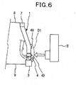
center pillar 1 that opposes the bumper of another vehicle B during a vehicle side collision, as illustrated inFIG. 6 (the figure illustrates a barrier used in a collision test), there is positioned a rear end of animpact beam 4 disposed in the front-rear direction at the lower portion in a front door D1 that opens and closes a front door opening frontward of thecenter pillar 1, and also there is disposed ahinge member 49, which hinges the front edge of a rear door that opens and closes the rear door opening in the rear of thecenter pillar 1.
During a side collision, therefore, a substantial collision load acts on the lower portion of thecenter pillar 1, via thehinge member 49 and the rear end of theimpact beam 4. In this case, thepillar reinforcement 2 disposed in the pillar in the upper-to-lower direction of the pillar is not found to be strong enough to withstand the locally substantial acting force. The cross section of the pillar lower portion breaks down on account of the acting force. This results in collapse deformation in the vehicle width direction, as denoted by the virtual line inFIG. 6 . Once collapse deformation occurs, resistance to the collision load may be lost, so that the lower portion of the pillar bends significantly into a V-shape, and the entire pillar shifts in the vehicle width direction, thereby pressing the vehicle interior.
InFIG. 6 , thereference numeral 7 denotes a roof side rail to which the upper end of thecenter pillar 1 is connected, 8 denotes a roof, and 9 a floor. - The stiffness of the pillar could be reinforced by thickening the plate of the
pillar reinforcement 2, and/or by increasing pillar stiffness locally by way of a bulkhead that partitions a closed cross-section in the pillar in the upper-to-lower direction of the pillar, as disclosed inPatent document 2. -
Patent document 2 discloses the feature of reinforcing the stiffness of an intermediate portion of a center pillar in the upper-to-lower direction of the pillar. - Patent document 1: Japanese Patent Application Publication No.
2003-127901 JP-A-2003-127901 - Patent document 2: Japanese Patent Application Publication No.
9-20267 JP-A-9-20267 - Japanese Patent Application
JP9254810 - Japanese Patent Application
JP8002438 - Japanese Patent Application
JP2000108662 - To accommodate ever more safety-conscious users, the plate thickness of the
pillar reinforcement 2 can be made thicker in order to ensure safety during side collisions, but doing so results in a heavier vehicle, which is problematic. Likewise, providing bulkheads in the pillar results in a complex structure that entails lower productivity and higher costs, all of which is problematic.
Therefore, it is the object of the invention to realize a pillar structure for an automobile, that is simple and has good productivity, in which the stiffness of the pillar can be enhanced without incurring increased weight, and in which cross-sectional collapse of the pillar structure during a side collision can be reduced, to prevent thereby deformation of the pillar toward the vehicle interior. - The invention is defined in the appended claims. In an example a pillar erected along the vertical edge of a door opening at a side surface of the body of an automobile, such that an outer panel and an inner panel of the pillar form a closed cross section. At a site of the pillar where a collision load is likely to act strongly and locally during a vehicle side collision, a groove or crest portion having a substantially square C-shaped cross section is formed in either or both of a front face portion, of the outer panel having a hat-shaped cross section, that faces toward the front of the vehicle and a rear face portion thereof that faces toward the rear of the vehicle, the groove or crest portion being formed over the entire width of the front face portion and rear face portion in a substantially horizontal direction.
During a vehicle side collision, pillar collapse can be mitigated through stiffening of ridge portions of the groove or crest portion and that are formed, in the direction in which the load acts, in the pillar lower portion, even when a locally large collision load acts on account of the collision of the bumper of another vehicle against the lower portion of the pillar.
The pushing of the other vehicle gives rise to a bending force that acts on the lower portion of the pillar. However, the lower portion of the pillar does not collapse easily, and hence the resistance of the pillar toward the bending force can be preserved, so that the lower portion of the pillar does not bend and deform extensively into a C-shape. - The groove or crest portion is formed in the outer panel at a lower portion of the pillar that faces, in the vehicle width direction, an end of an impact beam that is provided at a lower portion inside a door and extends in the front-rear direction, upon closing of the door for closing and opening the door opening.
The groove or crest portion is formed at a hinge joint, on which the door is hinged, in the outer panel in the pillar lower portion.
Locally significant collision loads act on the pillar lower portion, in particular at a site corresponding to the end of an impact beam in the door, and at a hinge joint onto which a hinge member is mounted. Therefore, bending of the pillar can be reduced in a particularly effective way by forming the groove or crest portion at these sites, in the direction in which the collision load acts. - An explanation follows next on an embodiment in which the invention is used in the lower portion of a center pillar.
- As illustrated in
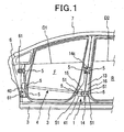
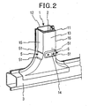
FIGS. 1 and2 , acenter pillar 1 is erected along the rear edge of a front door opening F at the side surface of a body. Thecenter pillar 1 is provided in such a mariner that the lower end thereof is joined to a front-rear intermediate position of arocker 3 that extends in the front-rear direction along the lower edge of the vehicle side surface, and in such a manner that the upper end of thecenter pillar 1 is joined to a front-rear intermediate position of aroof side rail 7 that extends in the front-rear direction along the upper edge of the vehicle side surface, whereby thecenter pillar 1 partitions the front door opening F from a rear door opening R. - The
center pillar 1 has anouter panel 11 having a substantially hat-shaped cross section that opens toward the vehicle interior, and aninner panel 12 that has a shallow hat-shaped cross section and is opened toward the vehicle exterior. Side-edge flanges at the front and rear sides of thepanels
Areinforcement 2 having a hat-shaped cross section is disposed along the inner face of theouter panel 11, inside thecenter pillar 1. Side-edge flanges at the front and rear sides of thereinforcement 2 are integrally joined to side-edge flanges of the outer andinner panels center pillar 1 is formed so as to widen somewhat, as it runs downward, in the front-rear direction as compared with the upper general portion of thecenter pillar 1. - As illustrated in
FIGS. 1 ,2 and3 , animpact beam 4 is disposed, in the front-rear direction, inside and at the lower portion of a front door D1 that opens and closes the front door opening F. Upon closing of the front door D1, therear end 41 of theimpact beam 4 stands at a position opposite, in the vehicle width direction, to the front half of the lower portion of anouter surface portion 13 of theouter panel 11 of thecenter pillar 1 that faces out of the vehicle. Afront end 40 of theimpact beam 4 is positioned so as to oppose the lower portion of afront pillar 6. - At the rear half of the lower portion of the
outer surface portion 13 at the bottom of thecenter pillar 1 there is formed ahinge joint 14 for joining to a hinge member 49 (FIG. 3 ) at the lower end side of the front edge of a rear door D2 that opens and closes the rear door opening R. Thehinge joint 14 has screw holes formed in a projection of theouter surface portion 13 that protrudes slightly out of the vehicle. Thehinge member 49 is bolted into these screw holes. Similarly to thehinge joint 14, ahinge joint 14a for hinging the upper end side of the front edge of the rear door D2 is provided at the intermediate portion of thecenter pillar 1 in the upper-to-lower direction of thepillar 1. - A
shallow groove 5, having a substantially square C-shaped cross section, is formed at afront face portion 15 that faces toward the front door opening F (frontward), at the lower portion of thecenter pillar 1 that opposes therear end 41 of theimpact beam 4 of the front door D1 and that is provided with thehinge joint 14 for the rear door D2. Thegroove 5 is formed substantially horizontally and extends from a bent portion at the boundary between thefront portion 15 and theouter surface portion 13, across the entire vehicle width direction of thefront face portion 15, up to the side-edge flange to which theinner panel 12 is joined. As a result,respective ridge portions groove 5 and at the upper and lower sides of the bottom face of thegroove 5. - A
groove 5, corresponding and identical to thegroove 5 of thefront face portion 15, is provided, at substantially the same height, over the entire width in the vehicle width direction of arear face portion 16, at the lower portion of thecenter pillar 1, that faces toward the rear door opening R (rearward).
Thegrooves front face portion 15 and therear face portion 16 are positioned at substantially the same height as thehinge joint 14. Thegroove 5 of therear face portion 16 has substantially the same width in the upper-to-lower direction of the pillar as that of thehinge joint 14, and is contiguous to the rear end of thehinge joint 14. - During a vehicle side collision, a locally large collision load acts on the lower portion of the
center pillar 1, via therear end 41 of theimpact beam 4 of the front door D1 and via thehinge member 49 of the rear door D2. In such a situation, the upper andlower ridge portions grooves front face portion 15 and therear face portion 16, which extend in the direction in which the collision load acts, receive the collision load at the lower portion of thecenter pillar 1. Collapse deformation of the lower portion of thecenter pillar 1 is reduced thereby. Bending of thecenter pillar 1 caused by the above collapse is suppressed as a result (FIG. 3B ). - When a yet larger collision load acts on the lower portion of the
center pillar 1, as indicated by the white arrow ofFIG. 4 , the acting load causes the lower portion of the pillar to bend into a V shape, as illustrated inFIG. 4 , about the point at which the pillar opposes the rear end of the impact beam and the hinge member. However, theridge portions ridge portions - In the present embodiment, the
concave grooves 5 have a cross section shaped as a C. However, thegrooves 5 may also be convex crest portions having a cross section shaped as an inverse C.
Also, there may be formed a pair of narrow beads that extend horizontally in the vehicle width direction and is spaced apart in the upper-to lower direction, at the front face portion and the rear face portion of the outer panel of the pillar lower portion, so that a groove having a square C-shaped cross section is formed by the two beads and by the panel surface between the beads. - The height, shape and height of the bumper of the other vehicle are subjected to variation during a vehicle side collision. Therefore, the safety of the vehicle interior can be secured to a yet greater extent by using the structure of the invention not only in the lower portion of the
center pillar 1, but also at a position corresponding to the hinge joint 14a that is located at an intermediate position of thecenter pillar 1 in the upper-to-lower direction of the pillar and that hinges the upper portion of the front edge of the rear door D2, as illustrated inFIG. 1 ; or at a position corresponding to upper and lower hinge joints 61, 61 of thefront pillar 6 that hinge the top and bottom front edges of the front door D1; or at an intermediate position of thefront pillar 6 corresponding to thebase plate 40 of theimpact beam 4 of the front door D1; or at an intermediate position of the center pillar or a rear pillar, not shown in the figures, corresponding to a door lock of the front door and/or the rear door. -
-
FIG. 1 is a schematic side-view diagram of an automobile in which the pillar structure of the invention is used; -
FIG. 2 is a schematic perspective-view diagram of the lower portion of a center pillar of an automobile in which the invention is used; -
FIGS. 3A , B are schematic diagrams illustrating a center pillar in an automobile in which the invention is used, before collision (FIG. 3A ) and after collision (FIG. 3B ), in a side collision experiment; -
FIG. 4 is a schematic diagram illustrating deformation of a center pillar when acted upon by a substantial collision load; -
FIG. 5 is a schematic perspective-view diagram of the lower portion of a conventional center pillar of an automobile; and -
FIG. 6 is a schematic diagram illustrating the deformed state in a side collision experiment conducted on a center pillar having a conventional structure. -
- F, R
- door opening
- 1
- center pillar
- 11
- outer panel
- 12
- inner panel
- 13
- outer surface portion
- 14
- hinge joint
- 15
- front face portion
- 16
- rear face portion
- 4
- impact beam
- 41
- rear end (end)
- 49
- hinge member
- 5
- groove (crest portion)
- 51
- ridge portion of groove (crest portion)
- 6
- front pillar
- D1, D2
- door
Claims (2)
- A pillar structure for an automobile, the pillar structure comprising:a center pillar (1), and a hinge joint (14) for a rear door, said hinge joint (14) provided at an outer surface (13) of the center pillar in a vehicle width direction;the center pillar (1) comprising:first and second grooves (5) provided on the center pillar (1) and extending in the vehicle width direction; whereinthe first groove (5) is provided at a front face portion (15) of the center pillar (1) and the second groove (5) is provided at a rear face portion (16) of the center pillar (1) in alignment with said first groove (5); and whereinthe hinge joint (14) is arranged on a portion of the outer surface (13) of the center pillar (1) between the first and second grooves (5).
- The pillar structure according to claim 1 wherein ridge portions (51) are provided in the horizontal direction at the upper and lower sides of the grooves (5).
Applications Claiming Priority (2)
| Application Number | Priority Date | Filing Date | Title |
|---|---|---|---|
| JP2007316533A JP5104264B2 (en) | 2007-12-07 | 2007-12-07 | Automobile pillar structure |
| PCT/JP2008/070394 WO2009072371A1 (en) | 2007-12-07 | 2008-11-10 | Pillar structure for automobile |
Publications (3)
| Publication Number | Publication Date |
|---|---|
| EP2216237A1 EP2216237A1 (en) | 2010-08-11 |
| EP2216237A4 EP2216237A4 (en) | 2011-05-04 |
| EP2216237B1 true EP2216237B1 (en) | 2013-04-03 |
Family
ID=40717552
Family Applications (1)
| Application Number | Title | Priority Date | Filing Date |
|---|---|---|---|
| EP08857222A Expired - Fee Related EP2216237B1 (en) | 2007-12-07 | 2008-11-10 | Pillar structure for automobile |
Country Status (7)
| Country | Link |
|---|---|
| US (1) | US8262152B2 (en) |
| EP (1) | EP2216237B1 (en) |
| JP (1) | JP5104264B2 (en) |
| CN (1) | CN101827744B (en) |
| AU (1) | AU2008332490B2 (en) |
| CA (1) | CA2695928C (en) |
| WO (1) | WO2009072371A1 (en) |
Families Citing this family (34)
| Publication number | Priority date | Publication date | Assignee | Title |
|---|---|---|---|---|
| SE531499C2 (en) * | 2007-11-15 | 2009-04-28 | Gestamp Hardtech Ab | B-pillar for vehicles |
| JP5131065B2 (en) * | 2008-07-14 | 2013-01-30 | トヨタ自動車株式会社 | Vehicle pillar structure and manufacturing method thereof. |
| US8292353B2 (en) | 2009-12-01 | 2012-10-23 | Toyota Motor Engineering & Manufacturing North America, Inc. | Construction for an automotive vehicle |
| CN101905715A (en) * | 2010-06-04 | 2010-12-08 | 刘文起 | Foil laminating type birdcage-shaped automobile body structure and automobile structure employing same |
| JP5601143B2 (en) * | 2010-10-20 | 2014-10-08 | マツダ株式会社 | Vehicle frame structure |
| JP5654045B2 (en) * | 2010-12-13 | 2015-01-14 | 本田技研工業株式会社 | Vehicle side structure |
| US8757709B2 (en) * | 2010-12-20 | 2014-06-24 | Tesla Motors, Inc. | Reinforced B-pillar assembly with reinforced rocker joint |
| JP5590232B2 (en) * | 2011-05-17 | 2014-09-17 | トヨタ自動車株式会社 | Body frame structure |
| US20120313400A1 (en) * | 2011-06-13 | 2012-12-13 | Jason Scott Balzer | Vehicle pillar assembly |
| US8827355B2 (en) * | 2011-09-01 | 2014-09-09 | Toyota Jidosha Kabushiki Kaisha | Vehicle body structure |
| JP5582262B2 (en) * | 2011-12-07 | 2014-09-03 | トヨタ自動車株式会社 | Lower body structure |
| BR112014029251A2 (en) * | 2012-05-24 | 2017-06-27 | Zephyros Inc | vehicle body frame cut zones |
| DE102012015463B4 (en) * | 2012-08-07 | 2020-09-17 | Volkswagen Aktiengesellschaft | Body pillar, in particular B-pillar for a vehicle |
| JP6010386B2 (en) * | 2012-08-09 | 2016-10-19 | シロキ工業株式会社 | Standing sash of door frame |
| DE102013002421B4 (en) * | 2013-02-11 | 2017-05-11 | Audi Ag | B-pillar, for a motor vehicle |
| DE102013018324A1 (en) * | 2013-10-31 | 2015-04-30 | GM Global Technology Operations LLC (n. d. Ges. d. Staates Delaware) | Automotive body |
| DE102014201198B3 (en) * | 2014-01-23 | 2015-05-28 | Volkswagen Aktiengesellschaft | Body pillar, in particular B pillar for a vehicle |
| FR3027274B1 (en) * | 2014-10-20 | 2018-03-23 | Psa Automobiles Sa. | LONGERON OF BODY OF VEHICLE WITH STIFFENER AND PARTITIONS. |
| JP6226335B2 (en) * | 2015-03-16 | 2017-11-08 | 本田技研工業株式会社 | Body structure |
| JP6409724B2 (en) * | 2015-09-18 | 2018-10-24 | マツダ株式会社 | Car side body structure |
| DE102015225689B3 (en) * | 2015-12-17 | 2017-01-26 | Volkswagen Aktiengesellschaft | Body pillar, in particular B pillar, for a vehicle |
| DE102016001241A1 (en) * | 2016-02-04 | 2017-08-10 | GM Global Technology Operations LLC (n. d. Ges. d. Staates Delaware) | Structure node for a motor vehicle body |
| JP6698393B2 (en) * | 2016-03-24 | 2020-05-27 | 株式会社Subaru | Body side structure |
| JP6421803B2 (en) * | 2016-09-08 | 2018-11-14 | トヨタ自動車株式会社 | Vehicle side structure |
| CN110191839B (en) * | 2017-01-20 | 2022-04-01 | 本田技研工业株式会社 | Vehicle body front structure |
| JP6751817B2 (en) * | 2017-06-02 | 2020-09-09 | 本田技研工業株式会社 | Vehicle panels and their manufacturing methods |
| KR102371245B1 (en) * | 2017-07-11 | 2022-03-04 | 현대자동차 주식회사 | Center pillar structure for vehicle |
| CN108058746A (en) * | 2018-01-10 | 2018-05-22 | 北京汽车研究总院有限公司 | Knocker component and with its vehicle |
| US10787064B2 (en) * | 2018-10-25 | 2020-09-29 | Toyota Motor Engineering & Manufacturing North America, Inc. | Door assemblies and vehicles including outer and inner bulkheads to transfer a side impact load to a pillar structure and methods incorporating the same |
| US11136065B2 (en) | 2020-02-24 | 2021-10-05 | Ford Global Technologies, Llc | Extended roof reinforcement structure |
| JP2021147012A (en) * | 2020-03-23 | 2021-09-27 | 本田技研工業株式会社 | Car body |
| CN112009217A (en) * | 2020-07-23 | 2020-12-01 | 中国第一汽车股份有限公司 | Composite material vehicle door anti-collision beam and preparation method thereof |
| CN115214786B (en) * | 2021-12-20 | 2024-03-26 | 广州汽车集团股份有限公司 | Front structure of automobile body and automobile |
| US11745666B1 (en) | 2022-02-17 | 2023-09-05 | Adrian Steel Company | Wall reinforcement and shelf system for a vehicle |
Family Cites Families (10)
| Publication number | Priority date | Publication date | Assignee | Title |
|---|---|---|---|---|
| JP2866950B2 (en) * | 1990-09-28 | 1999-03-08 | キヤノン株式会社 | Facsimile apparatus and control method thereof |
| JP2554439Y2 (en) * | 1991-06-19 | 1997-11-17 | いすゞ自動車株式会社 | Door striker mounting structure |
| JPH082438A (en) * | 1994-06-23 | 1996-01-09 | Nissan Motor Co Ltd | Vehicle body side part structure for automobile |
| JPH0920267A (en) | 1995-07-07 | 1997-01-21 | Hino Motors Ltd | Pillar structure of automobile |
| JP3496175B2 (en) * | 1996-03-19 | 2004-02-09 | 関東自動車工業株式会社 | Car body structure |
| JP2000108662A (en) | 1998-10-06 | 2000-04-18 | Fuji Heavy Ind Ltd | Car body side structure |
| JP4045034B2 (en) * | 1998-10-15 | 2008-02-13 | 本田技研工業株式会社 | Center pillar structure |
| JP3783546B2 (en) * | 2000-10-11 | 2006-06-07 | 三菱自動車工業株式会社 | Vehicle side sill structure |
| JP4045775B2 (en) | 2001-10-24 | 2008-02-13 | マツダ株式会社 | Car side body structure |
| JP2005067582A (en) * | 2003-08-01 | 2005-03-17 | Nissan Motor Co Ltd | Vehicle body structure |
-
2007
- 2007-12-07 JP JP2007316533A patent/JP5104264B2/en not_active Expired - Fee Related
-
2008
- 2008-11-10 EP EP08857222A patent/EP2216237B1/en not_active Expired - Fee Related
- 2008-11-10 CA CA2695928A patent/CA2695928C/en not_active Expired - Fee Related
- 2008-11-10 US US12/679,120 patent/US8262152B2/en not_active Expired - Fee Related
- 2008-11-10 WO PCT/JP2008/070394 patent/WO2009072371A1/en active Application Filing
- 2008-11-10 AU AU2008332490A patent/AU2008332490B2/en not_active Ceased
- 2008-11-10 CN CN2008801024792A patent/CN101827744B/en not_active Expired - Fee Related
Also Published As
| Publication number | Publication date |
|---|---|
| AU2008332490A1 (en) | 2009-06-11 |
| CA2695928C (en) | 2011-09-13 |
| AU2008332490B2 (en) | 2011-05-19 |
| WO2009072371A1 (en) | 2009-06-11 |
| CN101827744A (en) | 2010-09-08 |
| EP2216237A4 (en) | 2011-05-04 |
| CA2695928A1 (en) | 2009-06-11 |
| US20100231003A1 (en) | 2010-09-16 |
| JP2009137467A (en) | 2009-06-25 |
| CN101827744B (en) | 2012-08-22 |
| JP5104264B2 (en) | 2012-12-19 |
| US8262152B2 (en) | 2012-09-11 |
| EP2216237A1 (en) | 2010-08-11 |
Similar Documents
| Publication | Publication Date | Title |
|---|---|---|
| EP2216237B1 (en) | Pillar structure for automobile | |
| US9676419B2 (en) | Vehicle body bottom structure | |
| JP4555210B2 (en) | Auto body structure | |
| EP2030872B1 (en) | Lower structure of vehicle body | |
| US8979174B2 (en) | Small overlap frontal impact countermeasure | |
| US8757708B2 (en) | Motor vehicle body having structure-reinforcing front frame attachment | |
| RU2613750C1 (en) | Design of side part of vehicle body | |
| WO2015190034A1 (en) | Rear body structure for automobiles | |
| EP2740621A1 (en) | Back door structure for vehicle | |
| TW200948633A (en) | Vehicle door structure and method for fabricating the same | |
| US20190233013A1 (en) | Vehicle body rear structure | |
| JP5328057B2 (en) | Energy absorbing beam for vehicle and door structure for vehicle | |
| JP4764035B2 (en) | Automotive panel structure | |
| US11400984B2 (en) | Vehicle body side part structure | |
| JP4834353B2 (en) | Energy absorbing beam for vehicle and door structure for vehicle | |
| JP4015896B2 (en) | Car body structural materials and anti-collision reinforcement | |
| JP5513084B2 (en) | Energy absorbing beam for vehicle and door structure for vehicle | |
| JP2006213126A (en) | Body structure of automobile | |
| CN112119003B (en) | Vehicle body structure of vehicle | |
| JP2011110945A (en) | Energy absorbing beam for vehicle and door structure for vehicle | |
| WO2023189863A1 (en) | Impact bar attachment structure | |
| US20230001988A1 (en) | Vehicle rear portion structure | |
| CN116061660A (en) | Vehicle side collision bearing system and vehicle | |
| KR20230067362A (en) | Vehicle intermediate structure |
Legal Events
| Date | Code | Title | Description |
|---|---|---|---|
| PUAI | Public reference made under article 153(3) epc to a published international application that has entered the european phase |
Free format text: ORIGINAL CODE: 0009012 |
|
| 17P | Request for examination filed |
Effective date: 20100225 |
|
| AK | Designated contracting states |
Kind code of ref document: A1 Designated state(s): AT BE BG CH CY CZ DE DK EE ES FI FR GB GR HR HU IE IS IT LI LT LU LV MC MT NL NO PL PT RO SE SI SK TR |
|
| AX | Request for extension of the european patent |
Extension state: AL BA MK RS |
|
| DAX | Request for extension of the european patent (deleted) | ||
| A4 | Supplementary search report drawn up and despatched |
Effective date: 20110405 |
|
| 17Q | First examination report despatched |
Effective date: 20120328 |
|
| GRAP | Despatch of communication of intention to grant a patent |
Free format text: ORIGINAL CODE: EPIDOSNIGR1 |
|
| RAP1 | Party data changed (applicant data changed or rights of an application transferred) |
Owner name: TOYOTA SHATAI KABUSHIKI KAISHA |
|
| GRAS | Grant fee paid |
Free format text: ORIGINAL CODE: EPIDOSNIGR3 |
|
| GRAA | (expected) grant |
Free format text: ORIGINAL CODE: 0009210 |
|
| RAP1 | Party data changed (applicant data changed or rights of an application transferred) |
Owner name: TOYOTA SHATAI KABUSHIKI KAISHA |
|
| AK | Designated contracting states |
Kind code of ref document: B1 Designated state(s): DE FR GB NL |
|
| RBV | Designated contracting states (corrected) |
Designated state(s): DE FR GB NL |
|
| REG | Reference to a national code |
Ref country code: GB Ref legal event code: FG4D |
|
| RIN1 | Information on inventor provided before grant (corrected) |
Inventor name: OOSUMI, AKIRA C/O TOYOTA SHATAI KABUSHIKI KAISHA Inventor name: OKUMURA, HIROSHI C/O TOYOTA SHATAI KABUSHIKI KAISH Inventor name: SHIBASAKI, SHINICHI C/O TOYOTA JIDOSHA KABUSHIKI K |
|
| REG | Reference to a national code |
Ref country code: DE Ref legal event code: R096 Ref document number: 602008023488 Country of ref document: DE Effective date: 20130529 |
|
| REG | Reference to a national code |
Ref country code: NL Ref legal event code: T3 |
|
| PGFP | Annual fee paid to national office [announced via postgrant information from national office to epo] |
Ref country code: FR Payment date: 20131108 Year of fee payment: 6 Ref country code: GB Payment date: 20131121 Year of fee payment: 6 Ref country code: DE Payment date: 20131106 Year of fee payment: 6 |
|
| PLBE | No opposition filed within time limit |
Free format text: ORIGINAL CODE: 0009261 |
|
| STAA | Information on the status of an ep patent application or granted ep patent |
Free format text: STATUS: NO OPPOSITION FILED WITHIN TIME LIMIT |
|
| PGFP | Annual fee paid to national office [announced via postgrant information from national office to epo] |
Ref country code: NL Payment date: 20131109 Year of fee payment: 6 |
|
| 26N | No opposition filed |
Effective date: 20140106 |
|
| REG | Reference to a national code |
Ref country code: DE Ref legal event code: R097 Ref document number: 602008023488 Country of ref document: DE Effective date: 20140106 |
|
| REG | Reference to a national code |
Ref country code: DE Ref legal event code: R119 Ref document number: 602008023488 Country of ref document: DE |
|
| REG | Reference to a national code |
Ref country code: NL Ref legal event code: V1 Effective date: 20150601 |
|
| GBPC | Gb: european patent ceased through non-payment of renewal fee |
Effective date: 20141110 |
|
| REG | Reference to a national code |
Ref country code: FR Ref legal event code: ST Effective date: 20150731 |
|
| PG25 | Lapsed in a contracting state [announced via postgrant information from national office to epo] |
Ref country code: NL Free format text: LAPSE BECAUSE OF NON-PAYMENT OF DUE FEES Effective date: 20150601 |
|
| PG25 | Lapsed in a contracting state [announced via postgrant information from national office to epo] |
Ref country code: DE Free format text: LAPSE BECAUSE OF NON-PAYMENT OF DUE FEES Effective date: 20150602 Ref country code: GB Free format text: LAPSE BECAUSE OF NON-PAYMENT OF DUE FEES Effective date: 20141110 |
|
| PG25 | Lapsed in a contracting state [announced via postgrant information from national office to epo] |
Ref country code: FR Free format text: LAPSE BECAUSE OF NON-PAYMENT OF DUE FEES Effective date: 20141201 |