EP2215954A1 - Dishwasher with heat pump - Google Patents
Dishwasher with heat pump Download PDFInfo
- Publication number
- EP2215954A1 EP2215954A1 EP09005447A EP09005447A EP2215954A1 EP 2215954 A1 EP2215954 A1 EP 2215954A1 EP 09005447 A EP09005447 A EP 09005447A EP 09005447 A EP09005447 A EP 09005447A EP 2215954 A1 EP2215954 A1 EP 2215954A1
- Authority
- EP
- European Patent Office
- Prior art keywords
- tub
- heat
- evaporator
- dishwasher
- water
- Prior art date
- Legal status (The legal status is an assumption and is not a legal conclusion. Google has not performed a legal analysis and makes no representation as to the accuracy of the status listed.)
- Granted
Links
Images


Classifications
-
- A—HUMAN NECESSITIES
- A47—FURNITURE; DOMESTIC ARTICLES OR APPLIANCES; COFFEE MILLS; SPICE MILLS; SUCTION CLEANERS IN GENERAL
- A47L—DOMESTIC WASHING OR CLEANING; SUCTION CLEANERS IN GENERAL
- A47L15/00—Washing or rinsing machines for crockery or tableware
- A47L15/42—Details
- A47L15/4291—Recovery arrangements, e.g. for the recovery of energy or water
-
- A—HUMAN NECESSITIES
- A47—FURNITURE; DOMESTIC ARTICLES OR APPLIANCES; COFFEE MILLS; SPICE MILLS; SUCTION CLEANERS IN GENERAL
- A47L—DOMESTIC WASHING OR CLEANING; SUCTION CLEANERS IN GENERAL
- A47L15/00—Washing or rinsing machines for crockery or tableware
- A47L15/42—Details
- A47L15/4214—Water supply, recirculation or discharge arrangements; Devices therefor
- A47L15/4225—Arrangements or adaption of recirculation or discharge pumps
-
- A—HUMAN NECESSITIES
- A47—FURNITURE; DOMESTIC ARTICLES OR APPLIANCES; COFFEE MILLS; SPICE MILLS; SUCTION CLEANERS IN GENERAL
- A47L—DOMESTIC WASHING OR CLEANING; SUCTION CLEANERS IN GENERAL
- A47L15/00—Washing or rinsing machines for crockery or tableware
- A47L15/42—Details
- A47L15/4246—Details of the tub
-
- A—HUMAN NECESSITIES
- A47—FURNITURE; DOMESTIC ARTICLES OR APPLIANCES; COFFEE MILLS; SPICE MILLS; SUCTION CLEANERS IN GENERAL
- A47L—DOMESTIC WASHING OR CLEANING; SUCTION CLEANERS IN GENERAL
- A47L15/00—Washing or rinsing machines for crockery or tableware
- A47L15/42—Details
- A47L15/4285—Water-heater arrangements
-
- F—MECHANICAL ENGINEERING; LIGHTING; HEATING; WEAPONS; BLASTING
- F28—HEAT EXCHANGE IN GENERAL
- F28D—HEAT-EXCHANGE APPARATUS, NOT PROVIDED FOR IN ANOTHER SUBCLASS, IN WHICH THE HEAT-EXCHANGE MEDIA DO NOT COME INTO DIRECT CONTACT
- F28D21/00—Heat-exchange apparatus not covered by any of the groups F28D1/00 - F28D20/00
- F28D21/0001—Recuperative heat exchangers
- F28D21/0012—Recuperative heat exchangers the heat being recuperated from waste water or from condensates
-
- F—MECHANICAL ENGINEERING; LIGHTING; HEATING; WEAPONS; BLASTING
- F28—HEAT EXCHANGE IN GENERAL
- F28D—HEAT-EXCHANGE APPARATUS, NOT PROVIDED FOR IN ANOTHER SUBCLASS, IN WHICH THE HEAT-EXCHANGE MEDIA DO NOT COME INTO DIRECT CONTACT
- F28D7/00—Heat-exchange apparatus having stationary tubular conduit assemblies for both heat-exchange media, the media being in contact with different sides of a conduit wall
- F28D7/0008—Heat-exchange apparatus having stationary tubular conduit assemblies for both heat-exchange media, the media being in contact with different sides of a conduit wall the conduits for one medium being in heat conductive contact with the conduits for the other medium
- F28D7/0016—Heat-exchange apparatus having stationary tubular conduit assemblies for both heat-exchange media, the media being in contact with different sides of a conduit wall the conduits for one medium being in heat conductive contact with the conduits for the other medium the conduits for one medium or the conduits for both media being bent
-
- Y—GENERAL TAGGING OF NEW TECHNOLOGICAL DEVELOPMENTS; GENERAL TAGGING OF CROSS-SECTIONAL TECHNOLOGIES SPANNING OVER SEVERAL SECTIONS OF THE IPC; TECHNICAL SUBJECTS COVERED BY FORMER USPC CROSS-REFERENCE ART COLLECTIONS [XRACs] AND DIGESTS
- Y02—TECHNOLOGIES OR APPLICATIONS FOR MITIGATION OR ADAPTATION AGAINST CLIMATE CHANGE
- Y02B—CLIMATE CHANGE MITIGATION TECHNOLOGIES RELATED TO BUILDINGS, e.g. HOUSING, HOUSE APPLIANCES OR RELATED END-USER APPLICATIONS
- Y02B30/00—Energy efficient heating, ventilation or air conditioning [HVAC]
- Y02B30/52—Heat recovery pumps, i.e. heat pump based systems or units able to transfer the thermal energy from one area of the premises or part of the facilities to a different one, improving the overall efficiency
-
- Y—GENERAL TAGGING OF NEW TECHNOLOGICAL DEVELOPMENTS; GENERAL TAGGING OF CROSS-SECTIONAL TECHNOLOGIES SPANNING OVER SEVERAL SECTIONS OF THE IPC; TECHNICAL SUBJECTS COVERED BY FORMER USPC CROSS-REFERENCE ART COLLECTIONS [XRACs] AND DIGESTS
- Y02—TECHNOLOGIES OR APPLICATIONS FOR MITIGATION OR ADAPTATION AGAINST CLIMATE CHANGE
- Y02B—CLIMATE CHANGE MITIGATION TECHNOLOGIES RELATED TO BUILDINGS, e.g. HOUSING, HOUSE APPLIANCES OR RELATED END-USER APPLICATIONS
- Y02B30/00—Energy efficient heating, ventilation or air conditioning [HVAC]
- Y02B30/56—Heat recovery units
Definitions
- the invention relates to a dishwasher and a method for its operation according to the preamble of the independent claims.
- the object of the present invention is to further improve the energy efficiency of a dishwasher.
- This object is solved by the independent claims. Accordingly, a heat pump with at least one condenser and at least one evaporator is used, with which the process water or the tub heat can be withdrawn and / or supplied.
- a wall of the tub is to understand a vertical wall of the tub, its ceiling and its bottom.
- the process water is conveyed in a conventional manner with a circulation pump from the sump below the tub via a pumped-circulation system in spray arms of the dishwasher.
- at least one condenser can be arranged on the sump, on the circulating pump and / or on the recirculation piping system in order to heat the process water there.
- This embodiment has the advantage that on the tub wall and in particular on the tub bottom complicated structures, which potentially are difficult to clean and / or obstruct the flow of water, can be omitted.
- the capacitor is at least partially disposed on the pump chamber of the circulating pump, since there is a large flow velocity, so that the heat can be transferred to the process water with high efficiency.
- the evaporator or, if several evaporators are present at least one of the evaporators is thermally coupled to the drainage area, through which water is discharged from the tub to the sewer system after use.
- the wastewater heat can be withdrawn.
- the in Fig. 1 schematically illustrated dishwasher has a tub 1 for receiving the items to be washed, such as cutlery, crockery or the like.
- the dishwasher has in a known manner (not shown) spray arms and a circulation pump for pumping process water from the sump 2 in the spray arms.
- the items to be washed are stored in one or more dish racks.
- a controller controls and controls the operations of all components. Such a configured device is known in the art.
- Fresh water is supplied to the device via a fresh water valve 3 and a softener 4. Used water is pumped by a drain pump 5 in a sewer line 6.
- the dishwasher further comprises a heat pump comprising a compressor 7, from which a heat pump medium is pumped to one or more condensers 8 where liquefaction takes place with the release of heat. From the condenser 8, the medium passes via at least one expansion valve 9a, 9b to at least one evaporator 10a, 10b, where the medium evaporates by absorbing heat. From the evaporator 10a, 10b, the medium flows back to the compressor. 7
- expansion valve includes any type of capillaries, restrictors or the like, which are suitable for reducing the pressure of the pumped in the heat pump medium before the evaporator.
- a first condenser 8 is arranged on the bottom 12 of the tub and with this in direct, heat-conducting contact and / or arranged on the inside of the tub wall, so that the bottom 12 resp. the process water in the region of the condenser 8 can be heated.
- evaporators 10a, 10b provided, each of which is associated with its own expansion valve 9a, 9b. Further, a switch 14 is provided in front of the expansion valves to selectively supply the pumped medium to one or the other evaporator 10a or 10b.
- the first evaporator 10a is thermally coupled to the tub 1, preferably by being disposed on a first sidewall 15 thereof. Thus, with the first evaporator 10a of the tub 1 and in particular the said side wall 15 can be cooled.
- the second evaporator 10b is thermally coupled to a drainage area 16 of the appliance, the term "drainage area” indicating a region through which the water from the tub 1 is discharged to the drainage pipe 6 after use. Thus, with the second evaporator 10b heat can be withdrawn from the drain region 16 and in particular the water there.
- the drain area 16 is in the embodiment Fig. 1 from an outlet pipe 17, on or in which the tubular second evaporator 10b is guided along, wherein the drain pipe 17 and the second evaporator 10b are thermally connected to each other.
- drain pipe 17 and evaporator 10b are preferably meandering or spirally laid.
- the water in the discharge pipe 17 preferably runs in the opposite direction to the medium in the second evaporator 10b.
- the medium from the first evaporator 10a and from the second evaporator 10b is recombined in a combination valve or a second switch 18 upstream of the compressor 7.
- step 9 can be enhanced by, as shown, the capacitor 8 is arranged only on a side facing away from the first side wall 15 region of the bottom 12.
- the heat pump serves two purposes. On the one hand, it is used to transfer heat from the drainage area 16 into the tub 1 or the water present there. Further, it is used to extract the air in the tub 1 during drying water.
- the two evaporators 10a and 10b are used alternatively. By each evaporator associated with its own expansion valve 9a and 9b, the expansion valves can be optimally adapted to the sizes and desired operating temperatures of the two evaporators.
- the switch 14 can be arranged in the high pressure region, where the flow resistance plays a smaller role.
- steps 5 and 8 heat is transferred from the respective preceding process phase into the current process phase. Depending on the number of process phases, further such steps may take place. In each case, at the end of the process phase, the cooled water in the discharge area 16 is replaced with used, warm water.
- Fig. 2 a simpler embodiment of a dishwasher, in which only the first evaporator 10a is present.
- the second evaporator 10b is omitted, which simplifies the construction.
- the heat pump is only used to assist drying.
- Fig. 3 an alternative embodiment shown in which only the second Evaporator 10b available and the first evaporator 10a is omitted. Again, the design is simplified. In this case, the heat pump is used to transfer heat from one process phase to a later process phase.
- FIG. 4 Another version is in Fig. 4 shown.
- a bypass valve 20 is provided, with which water can be discharged from the tub 1, optionally bypassing the discharge area 16 from the device to the drain line 6.
- the intermediate rinsing phase does not necessarily require heat, so that with the structure according to Fig. 4 the process flow described above can be changed to the effect that the heat pump in the intermediate rinse phase, ie in step 5, is not operated.
- the water is then not discharged into the drainage area 16, but bypassing the drainage area 16 directly to the drainage line 6.
- the heat from the hot water of the main cleaning phase can be pumped into the tub. This avoids unnecessary heat loss.
- the intermediate rinse phase can be shortened since no heat transfer is required.
- FIG. 5 Another version of the dishwasher is in Fig. 5 shown.
- an additional circulation pump 21 and a changeover valve 22 are provided at the end of the discharge area 16, so that the water in the discharge area 16 can be pumped.
- the heat transfer between the second evaporator 10 b and the water in the discharge region 16 can be accelerated.
- the water is passed through a tank 22 in the drainage area.
- the tank 22 takes over the storage task of the drain pipe 17, but is characterized by a better use of space. However, care should be taken in this case that the tank 22 is designed so that the smallest possible mixing with the old wastewater takes place when new wastewater flows. In addition, the tank 22 must be designed so that as little as possible contaminants can deposit. When using a drain pipe 17, the risk of mixing and contamination deposition is generally lower.
- FIG. 8 A preferred construction of this heat exchanger is in Fig. 8 shown.
- the evaporator 10 b is arranged in a longitudinal recess of the drain pipe 17.
- the drain pipe is designed as a plastic blower and presses elastically against the evaporator 10b.
- a circulation pump 25 is shown, with which the process water from the sump 2 is conveyed below the tub 1 via a pumped circulation system 26 in the spray arms of the dishwasher.
- the first condenser 8 is arranged on the circulating pump 25. However, it is also conceivable for at least a partial arrangement at the sump 2 and / or a pumped circulation system 26. It in turn serves to supply heat to the process water during the cleaning phase. During this phase, the process water is pumped through the sump 2, the pump 25 and the pumped circulation system 26, so that they can be specifically heated there.
- a second capacitor 8 ' is provided be. This is in the dry phase together with the first evaporator 10a in operation to extract water from the process air in the manner described above.
- the second condenser 8 ' is arranged on a second side wall 15', which is opposite the first side wall 15 with the first evaporator 10a, so that good convection can be produced.
- the arrangement of the second capacitor 8 'on a side wall also has the advantage that the second condenser does not heat the water which drains through the bottom 12 in the dry phase, but selectively delivers its heat to the process air.
- the first condenser 8 and the second evaporator 10b are arranged in series with the expansion valve 9b interposed therebetween, so that the cooling medium can be passed through the first condenser 8 and the second evaporator 10b during the purge phase so as to extract heat from the drain area 16in to promote the process water.
- a switch 14' may be arranged to selectively supply the pumped medium to the first and the second capacitor 8 and 8 '.
- the first capacitor 8 in the embodiment after Fig. 9 preferably arranged on the circulation pump 25.
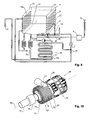
- a possible embodiment of the pump 25 with the first capacitor 8 is in Fig. 10 shown.
- the construction of the pump corresponds approximately to that according to DE 20 2007 017 077 U1 ,
- the pump has a housing 28 in which a pumping chamber 27 is arranged.
- a pumping chamber 27 In the pumping chamber 27 is an impeller (not visible in the figures), which is rotated by a motor 29 about a rotation axis 30.
- the construction of the pump for example Fig. 2 from DE 20 2007 017 077 U1 directed.
- the pumping chamber 27 has a cylindrical, to the axis of rotation 30 concentrically arranged wall 31.
- the majority of the pipeline of the first capacitor 8 meanders on the wall 31.
- the pipeline has a plurality of straight sections 32 parallel to the axis of rotation 30, which are connected via U-shaped bent portions 33 with each other.
- Fig. 10 extends the pipe of the condenser 8 into the axial, perpendicular to the axis of rotation 30 end wall 35 of the pumping chamber 27, whereby the heat exchange can be improved.
- the pipeline of the capacitor is arranged only on the cylindrical wall 31 of the pumping chamber 27.
- the pipeline of the condenser 8 can, as in Fig. 10 shown outside on the wall of the pumping chamber 27, or (as in below Fig. 11 shown) on the inside.
- FIG. 11 Another embodiment of the circulation pump 25 is in Fig. 11 which merely shows the cylindrical wall 31 of the pumping chamber 27.
- the pipeline of the capacitor 8 extends in a helix along the cylindrical wall 31.
- the helix is arranged coaxially to the axis of rotation 30.
- FIGS. 12 and 13 show a third embodiment of the circulation pump 25.
- the chamber 40 extends cylindrically around the pumping chamber 27.
- the wall of the housing 28 of the pumping chamber is double-walled.
- the medium is introduced via a first connecting piece 41 into the chamber 40 and discharged via a second connecting piece 42 again.
- a resistive heater may be provided, ie a heater which generates heat by passing an electrical current through a resistor.
- a heater allows, for example, to heat the water faster if necessary or to higher temperatures than would be possible with the condenser 8 alone.
- this heater is shown by reference numeral 36 and cuffed around an intake pipe 37, through which the water is sucked into the circulation pump 25.
Abstract
Description
Die Erfindung betrifft einen Geschirrspüler sowie ein Verfahren zu dessen Betrieb gemäss Oberbegriff der unabhängigen Ansprüche.The invention relates to a dishwasher and a method for its operation according to the preamble of the independent claims.
Um die Energieeffizienz von Geschirrspülern zu verbessern, wurde u.a. vorgeschlagen, einen Wärmetauscher vorzusehen, welcher dazu dient, dem Bottich Wärme zu entziehen und sie dem Frischwasser zuzuführen.In order to improve the energy efficiency of dishwashers, i.a. proposed to provide a heat exchanger which serves to extract heat from the tub and supply it to the fresh water.
Aufgabe der vorliegenden Erfindung ist es, die Energieeffizienz eines Geschirrspülers weiter zu verbessern. Diese Aufgabe wird von den unabhängigen Ansprüchen gelöst. Demgemäss wird eine Wärmepumpe mit mindestens einem Kondensator und mindestens einem Verdampfer eingesetzt, mit denen dem Prozesswasser oder dem Bottich Wärme entzogen und/oder zugeführt werden kann.The object of the present invention is to further improve the energy efficiency of a dishwasher. This object is solved by the independent claims. Accordingly, a heat pump with at least one condenser and at least one evaporator is used, with which the process water or the tub heat can be withdrawn and / or supplied.
Vorzugsweise wird der Kondensator bzw. (falls mehrere Kondensatoren vorhanden sind) mindestens einer der Kondensatoren und/oder der Verdampfer bzw. (falls mehrere Verdampfer vorhanden sind) mindestens einer der Verdampfer an einer Wand des Bottichs angeordnet, insbesondere dieser Wand entlang verlaufend, wodurch in einfacher Weise, d.h. ohne spezielle Wärmetauschvorrichtungen etc., ein direkter Wärmeeintrag bzw. ein direkter Wärmeentzug ermöglicht wird. Unter "Wand" des Bottichs ist dabei eine vertikale Wand des Bottichs, dessen Decke sowie auch dessen Boden zu verstehen.Preferably, the capacitor or (if more than one capacitor is present) at least one of the capacitors and / or the evaporator or (if more evaporators are present) arranged at least one of the evaporator on a wall of the tub, in particular this wall along running, whereby in simple way, ie without special heat exchange devices etc., a direct heat input or a direct heat extraction is possible. Under "wall" of the tub is to understand a vertical wall of the tub, its ceiling and its bottom.
In einer vorteilhaften Ausgestaltung der Erfindung wird das Prozesswasser in an sich bekannter Weise mit einer Umwälzpumpe aus dem Sumpf unterhalb des Bottichs über ein Umpump-Leitungssystem in Sprüharme des Geschirrspülers gefördert. In diesem Falle kann mindestens ein Kondensator am Sumpf, an der Umwälzpumpe und/oder am Umpump-Leitungssystem angeordnet werden, um dort das Prozesswasser zu erwärmen. Diese Ausgestaltung hat den Vorteil, dass an der Bottichwand und insbesondere am Bottichboden komplizierte Strukturen, welche potenziell schwierig zu reinigen sind und/oder den Ablauf des Wassers behindern, entfallen können. Vorzugsweise wird der Kondensator mindestens teilweise an der Pumpenkammer der Umwälzpumpe angeordnet, da dort eine grosse Strömungsgeschwindigkeit herrscht, so dass die Wärme mit hoher Effizienz an das Prozesswasser übertragen werden kann.In an advantageous embodiment of the invention, the process water is conveyed in a conventional manner with a circulation pump from the sump below the tub via a pumped-circulation system in spray arms of the dishwasher. In this case, at least one condenser can be arranged on the sump, on the circulating pump and / or on the recirculation piping system in order to heat the process water there. This embodiment has the advantage that on the tub wall and in particular on the tub bottom complicated structures, which potentially are difficult to clean and / or obstruct the flow of water, can be omitted. Preferably, the capacitor is at least partially disposed on the pump chamber of the circulating pump, since there is a large flow velocity, so that the heat can be transferred to the process water with high efficiency.
In einer weiteren vorteilhaften Ausführung wird der Verdampfer bzw. (falls mehrere Verdampfer vorhanden sind) mindestens einer der Verdampfer thermisch mit dem Ablaufbereich gekoppelt, durch welchen Wasser vom Bottich nach Gebrauch an die Kanalisation abgegeben wird. So kann dem Abwasser Wärme entzogen werden.In a further advantageous embodiment, the evaporator or, if several evaporators are present, at least one of the evaporators is thermally coupled to the drainage area, through which water is discharged from the tub to the sewer system after use. Thus, the wastewater heat can be withdrawn.
Weitere bevorzugte Ausführungen der Erfindung ergeben sich aus den abhängigen Ansprüchen sowie aus der nun folgenden Beschreibung anhand der Figuren. Dabei zeigen:
-
Fig. 1 eine erste Ausführung eines Geschirrspülers, -
Fig. 2 eine zweite Ausführung eines Geschirrspülers mit nur einem Verdampfer, -
Fig. 3 eine dritte Ausführung eines Geschirrspülers mit nur einem Verdampfer, -
Fig. 4 eine vierte Ausführung eines Geschirrspülers mit Überbrückungsventil, -
Fig. 5 eine fünfte Ausführung eines Geschirrspülers mit zusätzlicher Zirkulationspumpe, -
Fig. 6 eine sechste Ausführung eines Geschirrspülers mit Abwassertank, -
Fig. 7 eine siebte Ausführung eines Geschirrspülers mit koaxialem Wärmetauscher, -
Fig. 8 einen Schnitt durch das Abwasserrohr einer weiteren Ausführung, -
Fig. 9 eine achte Ausführung des Geschirrspülers mit einem Kondensator an der Umwälzpumpe, -
Fig. 10 eine erste Ausführung der Umwälzpumpe, -
Fig. 11 einen Teil des Pumpengehäuses einer zweiten Ausführung der Umwälzpumpe, -
Fig. 12 eine dritte Ausführung der Umwälzpumpe und -
Fig. 13 einen Schnitt durch die Pumpkammer der Umwälzpumpe vonFig. 12 .
-
Fig. 1 a first embodiment of a dishwasher, -
Fig. 2 a second embodiment of a dishwasher with only one evaporator, -
Fig. 3 a third embodiment of a dishwasher with only one evaporator, -
Fig. 4 a fourth embodiment of a dishwasher with a bypass valve, -
Fig. 5 a fifth embodiment of a dishwasher with additional circulation pump, -
Fig. 6 a sixth embodiment of a dishwasher with waste water tank, -
Fig. 7 A seventh embodiment of a dishwasher with coaxial heat exchanger, -
Fig. 8 a section through the sewer pipe of another embodiment, -
Fig. 9 an eighth embodiment of the dishwasher with a condenser on the circulation pump, -
Fig. 10 a first embodiment of the circulation pump, -
Fig. 11 a part of the pump housing of a second embodiment of the circulation pump, -
Fig. 12 a third embodiment of the circulation pump and -
Fig. 13 a section through the pumping chamber of the circulation pump ofFig. 12 ,
Der in
Frischwasser wird dem Gerät über ein Frischwasserventil 3 und einen Enthärter 4 zugeführt. Gebrauchtes Wasser wird von einer Ablaufpumpe 5 in eine Abwasserleitung 6 abgepumpt. Auch diese Komponenten sind dem Fachmann grundsätzlich bekannt.Fresh water is supplied to the device via a
Der Geschirrspüler besitzt weiter eine Wärmepumpe umfassend einen Kompressor 7, von welchem ein Wärmepumpenmedium zu einem oder mehreren Kondensatoren 8 gepumpt wird, wo unter Abgabe von Wärme eine Verflüssigung stattfindet. Vom Kondensator 8 gelangt das Medium über mindestens ein Expansionsventil 9a, 9b zu mindestens einem Verdampfer 10a, 10b, wo das Medium unter Aufnahme von Wärme verdampft. Vom Verdampfer 10a, 10b läuft das Medium zurück zum Kompressor 7.The dishwasher further comprises a heat pump comprising a
Der Begriff "Expansionsventil" umfasst dabei jegliche Art von Kapillaren, Drosseln oder dergleichen, die geeignet sind, den Druck des in der Wärmepumpe gepumpten Mediums vor dem Verdampfer zu reduzieren.The term "expansion valve" includes any type of capillaries, restrictors or the like, which are suitable for reducing the pressure of the pumped in the heat pump medium before the evaporator.
In der in
Weiter sind in der in
Der erste Verdampfer 10a ist thermisch mit dem Bottich 1 gekoppelt, vorzugsweise indem er an einer ersten Seitenwand 15 desselben angeordnet ist. Somit kann mit dem ersten Verdampfer 10a der Bottich 1 und insbesondere die genannte Seitenwand 15 gekühlt werden.The
Der zweite Verdampfer 10b ist thermisch mit einem Ablaufbereich 16 des Geräts gekoppelt, wobei der Begriff "Ablaufbereich" einen Bereich kennzeichnet, durch welchen das Wasser vom Bottich 1 nach Gebrauch an die Abflussleitung 6 abgegeben wird. Somit kann mit dem zweiten Verdampfer 10b dem Ablaufbereich 16 und insbesondere dem dort vorhandenen Wasser Wärme entzogen werden.The
Konkret besteht der Ablaufbereich 16 in der Ausführung nach
Das Medium vom ersten Verdampfer 10a und vom zweiten Verdampfer 10b wird in einem Kombinationsventil oder einen zweiten Weiche 18 vor dem Kompressor 7 wieder zusammengeführt.The medium from the
Die Funktionsweise des Geräts ist wie folgt:
- 1. Zu Beginn einer Hauptreinigungsphase wird Frischwasser über
das Frischwasserventil 3 eingelassen. - 2. Gleichzeitig wird die Wärmepumpe gestartet, mit dem Ziel, Wärmeenergie aus dem
Wasser im Ablaufbereich 16 dem Bottich 1 zuzuführen. Hierzu wird dieWeiche 14 so eingestellt, dass der zweite Verdampfer 10b in Betrieb ist. Die Wärmepumpe wird abgeschaltet, wenn die Temperatur des Wassers im Ablaufbereich eine Schwelle, z.B. 5°C, unterschreitet. Erreicht die Temperatur im Bottich bzw. im Reinigungswasser dabei einen vorgegebenen Wert (je nach Programm z.B. zwischen 40° und 60°C) nicht, so kann zusätzlich elektrisch geheizt werden, entweder gleichzeitig mit oder nach dem Heizen mittels Wärmepumpe. - 3. Am Ende der Hauptreinigungsphase wird das Wasser aus dem Bottich in
den Ablaufbereich 16 abgelassen. Dort ersetzt es das Wasser, welches durch die Wärmepumpe in Schritt 2 abgekühlt wurde. - 4.
Über Frischwasserventil 3 wird neues Frischwasser für eine Zwischenspülphase eingelassen. - 5. Die Wärmepumpe wird wieder in Gang gesetzt, um die
Wärme vom Ablaufbereich 16 inden Bottich 1 zu fördern. Wiederum wird dabei dasWasser im Ablaufbereich 16 höchstens auf die erwähnte Schwelle von z.B. 5°C abgekühlt. Gleichzeitig wird die Zirkulationspumpe, welche Wasser vom Sumpf 2 in die Sprüharme fördert, vorzugsweise mindestens zeitweise mit geringer Leistung betrieben, und zwar derart, dass Wasser ohne Beaufschlagung des Spülguts aus dem unteren Sprüharm fliesst. Somit wird erreicht, dass das Wasser die Wärme vom ersten Kondensator 8 aufnehmen kann, ohne dass dabei das Spülgut vom kalten Wasser abgekühlt wird. Sobald dieWärme vom Ablaufbereich 16 getauscht ist, wird das Spülgut zwischengespült und sodann die Zwischenspülphase beendet. - 6. Das Wasser
aus dem Bottich 1 wird wiederum abgepumpt und ersetzt das kalteWasser im Ablaufbereich 16. - 7.
Über Frischwasserventil 3 wird neues Frischwasser für eine Glanzspülphase (Klarspülphase) eingelassen. - 8. Die Wärmepumpe wird wieder in Gang gesetzt, um die
Wärme vom Ablaufbereich 16 inden Bottich 1 zu fördern. Wiederum wird die Zirkulationspumpe, welche Wasser vom Sumpf 2 in die Sprüharme fördert, vorzugsweise mindestens zeitweise mit geringer Leistung betrieben, damit das Wasser zwar umgepumpt wird, ohne aber das Spülgut zu beaufschlagen. Sobald dieWärme vom Ablaufbereich 16 getauscht ist, und gegebenenfalls nach optionaler elektrischer Zusatzbeheizung, wird das Spülgut glanzgespült und sodann die Glanzspülphase beendet. Das Glanzspülwasser kann anden Ablaufbereich 16 abgegeben werden. - 9. Nun startet die Trockenphase.
Die Weiche 14 wird umgeschaltet, so dass nun der erste Verdampfer 10a im Kreislauf liegt, nicht aber der zweite Verdampfer 10b. Die Wärmepumpe wird gestartet. Somit wird derBoden 12 desBottichs 1vom Kondensator 8 erwärmt, während dieSeitenwand 15vom Verdampfer 10a abgekühlt wird. Dadurch entsteht einKonvektionsstrom im Bottich 1, indem Luftüber dem Kondensator 8 aufgewärmt wird und aufsteigt. Diese Luft durchströmt das Spülgut und trocknet dieses. Die Luft kommt sodannmit der Seitenwand 15 in Kontakt, wo sie abgekühlt wird, so dass ihr Wasser entzogen wird. Das auskondensierte Wasser läuft der Seitenwand 15 entlang nach unten und gelangt in den Sumpf 2.
- 1. At the beginning of a main cleaning phase, fresh water is introduced via the
fresh water valve 3. - 2. At the same time, the heat pump is started, with the aim of supplying heat energy from the water in the
drainage area 16 to thetub 1. For this purpose, theswitch 14 is set so that thesecond evaporator 10b is in operation. The heat pump is switched off when the temperature of the water in the discharge area falls below a threshold, eg 5 ° C. If the temperature in the tub or in the cleaning water does not reach a given value (eg between 40 ° and 60 ° C, depending on the program), additional electrical heating can be carried out either simultaneously with or after heating by means of a heat pump. - 3. At the end of the main cleaning phase, the water is drained from the tub into
drainage area 16. There it replaces the water that was cooled by the heat pump in step 2. - 4.
Fresh water valve 3 is used to introduce new fresh water for an intermediate rinse phase. - 5. The heat pump is restarted to promote the heat from the
drain region 16 into thetub 1. Again, the water is cooled in thedischarge area 16 at most to the mentioned threshold ofeg 5 ° C. At the same time the circulation pump, which promotes water from the sump 2 in the spray arms, preferably at least temporarily operated at low power, in such a way that water flows without applying the dishes from the lower spray arm. Thus, it is achieved that the water can absorb the heat from thefirst capacitor 8, without causing the dishes to be cooled by the cold water. Once the heat from thedrain area 16 is exchanged, the items to be washed are rinsed in and then the intermediate rinsing phase is ended. - 6. The water from the
tub 1 is in turn pumped out and replaces the cold water in thedrainage area 16. - 7. About
fresh water valve 3 new fresh water for a Glanzspülphase (rinse phase) is admitted. - 8. The heat pump is restarted to promote the heat from the
drain region 16 into thetub 1. Again, the circulation pump, which promotes water from the sump 2 in the spray arms, preferably at least temporarily operated at low power, so that the water is indeed pumped around, but without acting on the dishes. As soon as the heat has been exchanged by theoutlet region 16, and optionally after optional additional electrical heating, the items to be washed are gloss-rinsed and then the rinse cycle phase is ended. The rinse water can be delivered to thedrain area 16. - 9. Now the drying phase starts. The
switch 14 is switched, so that now thefirst evaporator 10a is in circulation, but not thesecond evaporator 10b. The heat pump is started. Thus, the bottom 12 of thetub 1 is heated by thecondenser 8 while theside wall 15 is cooled by theevaporator 10a. This creates a convection current in thetub 1 by air above thecondenser 8 is warmed up and rises. This air flows through the dishes and dries it. The air then comes in contact with theside wall 15, where it is cooled so that its water is removed. The condensed water runs down theside wall 15 and enters the sump. 2
Die Konvektion in Schritt 9 kann verstärkt werden, indem, wie gezeigt, der Kondensator 8 nur an einem von der ersten Seitenwand 15 abgewandten Bereich des Bodens 12 angeordnet ist.The convection in step 9 can be enhanced by, as shown, the
Aus dem obigen Prozessablauf ist ersichtlich, dass die Wärmepumpe zwei Zwecken dient. Einerseits wird sie dazu verwendet, Wärme aus dem Ablaufbereich 16 in den Bottich 1 bzw. das dort vorhandene Wasser zu transferieren. Weiter wird sie dazu eingesetzt, der Luft im Bottich 1 während der Trocknung Wasser zu entziehen. Dabei werden die beiden Verdampfer 10a und 10b alternativ eingesetzt. Indem jedem Verdampfer ein eigenes Expansionsventil 9a bzw. 9b zugeordnet ist, können die Expansionsventile den Grössen und gewünschten Betriebstemperaturen der beiden Verdampfer optimal angepasst werden. Zudem kann in diesem Fall die Weiche 14 im Hochdruckbereich angeordnet werden, wo deren Strömungswiderstand eine kleinere Rolle spielt. Es ist allerdings auch denkbar, nur ein gemeinsames Expansionsventil für beide Verdampfer 10a, 10b vorzusehen.It can be seen from the above process flow that the heat pump serves two purposes. On the one hand, it is used to transfer heat from the
Im obigen Beispiel wird in den Schritten 5 und 8 Wärme aus der jeweilig vorhergehenden Prozessphase in die laufende Prozessphase transferiert. Je nach Zahl der Prozessphasen können auch weitere solche Schritte stattfinden. Dabei wird jeweils am Ende der Prozessphase das abgekühlte Wasser im Ablaufbereich 16 mit gebrauchtem, warmem Wasser ersetzt.In the example above, in
Denkbar ist es auch, in der Trockenphase zumindest zeitweise den zweiten Verdampfer 10b zu betreiben, entweder zusammen (parallel) oder alternierend zum ersten Verdampfer, um so dem Bottich 1 noch weiter Wärme aus dem Ablaufbereich 16 zuzuführen.It is also conceivable, at least temporarily, to operate the
Die beiden oben genannten Funktionen der Wärmepumpe (Trocknungsprozess und Wärmetransfer) können auch einzeln eingesetzt werden. So zeigt
Entsprechend ist in
Eine weitere Ausführung ist in
Eine weitere Ausführung des Geschirrspülers ist in
In der Ausführung nach
In der Ausführung nach
Eine bevorzugte Konstruktion dieses Wärmetauschers ist in
Eine weitere Ausführung wird in
In
Der erste Kondensator 8 gemäss dieser Ausführung ist an der Umwälzpumpe 25 angeordnet. Denkbar ist jedoch auch eine mindestens teilweise Anordnung am Sumpf 2 und/oder a Umpump-Leitungssystem 26. Er dient wiederum dazu, dem Prozesswasser während der Reinigungsphase Wärme zuzuführen. Während dieser Phase wird das Prozesswasser durch den Sumpf 2, die Pumpe 25 sowie das Umpump-Leitungssystem 26 gefördert, so dass sie dort gezielt erwärmt werden kann.The
Um die Wärmepumpe in diesem Fall auch während der Trockenphase einsetzen zu können, kann zusätzlich an einer Wand des Bottichs 1 ein zweiter Kondensator 8' vorgesehen sein. Dieser ist in der Trockenphase zusammen mit dem ersten Verdampfer 10a in Betrieb, um der Prozessluft in der oben beschriebenen Weise Wasser zu entziehen.In order to use the heat pump in this case, even during the dry phase, in addition to a wall of the
Wie in
Vorzugsweise sind der erste Kondensator 8 und der zweite Verdampfer 10b in Serie angeordnet, mit dazwischen liegendem Expansionsventil 9b, so dass das Kühlmedium während der Reinigungsphase durch den ersten Kondensator 8 und den zweiten Verdampfer 10b geführt werden kann, um so Wärme aus dem Ablaufbereich 16 in das Prozesswasser zu fördern.Preferably, the
Wie aus
Wie erwähnt, wird der erste Kondensator 8 in der Ausführung nach
Der Aufbau der Pumpe entspricht dabei ungefähr jenem gemäss
Die Pumpkammer 27 besitzt eine zylindrische, zur Drehachse 30 konzentrisch angeordnete Wand 31. In der Ausführung nach
In der Ausführung nach
Die Rohrleitung des Kondensators 8 kann, wie in
Eine weitere Ausführung der Umwälzpumpe 25 ist in
Zusätzlich zum ersten Kondensator 8 kann an der Umwälzpumpe 25 und/oder am Umpump-Leitungssystem 26 eine resistive Heizung vorgesehen sein, d.h. eine Heizung, welche Wärme erzeugt, indem ein elektrischer Strom durch einen Widerstand geführt wird. Eine derartige Heizung erlaubt es z.B., das Wasser bei Bedarf schneller oder auf höhere Temperaturen aufzuheizen, als dies mit dem Kondensator 8 alleine möglich wäre. In der Ausführung nach
Claims (16)
Priority Applications (3)
| Application Number | Priority Date | Filing Date | Title |
|---|---|---|---|
| SI200931706T SI2215954T1 (en) | 2009-02-09 | 2009-04-17 | Dishwasher with heat pump |
| PL09005447T PL2215954T3 (en) | 2009-02-09 | 2009-04-17 | Dishwasher with heat pump |
| EP09005447.9A EP2215954B1 (en) | 2009-02-09 | 2009-04-17 | Dishwasher with heat pump |
Applications Claiming Priority (2)
| Application Number | Priority Date | Filing Date | Title |
|---|---|---|---|
| EP09001756A EP2064982B1 (en) | 2009-02-09 | 2009-02-09 | Dishwasher with heat pump |
| EP09005447.9A EP2215954B1 (en) | 2009-02-09 | 2009-04-17 | Dishwasher with heat pump |
Publications (2)
| Publication Number | Publication Date |
|---|---|
| EP2215954A1 true EP2215954A1 (en) | 2010-08-11 |
| EP2215954B1 EP2215954B1 (en) | 2017-05-17 |
Family
ID=40514576
Family Applications (5)
| Application Number | Title | Priority Date | Filing Date |
|---|---|---|---|
| EP11010220.9A Active EP2446796B1 (en) | 2009-02-09 | 2009-02-09 | Dishwasher with heat pump |
| EP11010219.1A Active EP2446795B1 (en) | 2009-02-09 | 2009-02-09 | Dishwasher with heat pump |
| EP09001756A Active EP2064982B1 (en) | 2009-02-09 | 2009-02-09 | Dishwasher with heat pump |
| EP09005448.7A Active EP2215955B1 (en) | 2009-02-09 | 2009-04-17 | Dishwasher with heat pump |
| EP09005447.9A Active EP2215954B1 (en) | 2009-02-09 | 2009-04-17 | Dishwasher with heat pump |
Family Applications Before (4)
| Application Number | Title | Priority Date | Filing Date |
|---|---|---|---|
| EP11010220.9A Active EP2446796B1 (en) | 2009-02-09 | 2009-02-09 | Dishwasher with heat pump |
| EP11010219.1A Active EP2446795B1 (en) | 2009-02-09 | 2009-02-09 | Dishwasher with heat pump |
| EP09001756A Active EP2064982B1 (en) | 2009-02-09 | 2009-02-09 | Dishwasher with heat pump |
| EP09005448.7A Active EP2215955B1 (en) | 2009-02-09 | 2009-04-17 | Dishwasher with heat pump |
Country Status (4)
| Country | Link |
|---|---|
| EP (5) | EP2446796B1 (en) |
| DK (5) | DK2064982T3 (en) |
| PL (5) | PL2064982T3 (en) |
| SI (3) | SI2064982T1 (en) |
Cited By (4)
| Publication number | Priority date | Publication date | Assignee | Title |
|---|---|---|---|---|
| EP2449945A2 (en) | 2012-01-30 | 2012-05-09 | V-Zug AG | Domestic appliance with heat pump on process water circuit |
| DE102013114273B4 (en) * | 2013-12-18 | 2019-11-14 | Miele & Cie. Kg | dishwasher |
| WO2020069800A1 (en) * | 2018-10-02 | 2020-04-09 | Arcelik Anonim Sirketi | A heat pump dishwasher comprising a defrost line |
| EP3988884A1 (en) * | 2020-10-20 | 2022-04-27 | Haier Deutschland GmbH | Dishwasher |
Families Citing this family (63)
| Publication number | Priority date | Publication date | Assignee | Title |
|---|---|---|---|---|
| DE102009045547A1 (en) * | 2009-10-09 | 2011-04-14 | BSH Bosch und Siemens Hausgeräte GmbH | Process for the recovery of energy from the heat of waste water from a water-conducting household appliance |
| DK2206824T3 (en) * | 2010-02-16 | 2013-10-07 | V Zug Ag | Household appliance with tub, heat pump and tank |
| IT1398885B1 (en) * | 2010-03-02 | 2013-03-21 | Indesit Co Spa | METHOD AND MACHINE FOR STOVES TREATMENT |
| DE102011000042A1 (en) * | 2011-01-05 | 2012-07-05 | Miele & Cie. Kg | Method for carrying out a washing program |
| EP2443983B1 (en) | 2012-01-27 | 2020-06-17 | V-Zug AG | Domestic appliance with heat pump underneath it |
| EP2443984B1 (en) | 2012-01-27 | 2020-06-17 | V-Zug AG | Coaxial heat exchanger for a domestic appliance |
| EP2662013A1 (en) | 2012-05-07 | 2013-11-13 | ELECTROLUX PROFESSIONAL S.p.A. | A dishwashing machine with a heat-pump drying device and associated method |
| DE102012207980A1 (en) * | 2012-05-14 | 2013-11-14 | BSH Bosch und Siemens Hausgeräte GmbH | Device for temporary storage of operating fluid |
| DE102012109363A1 (en) * | 2012-10-02 | 2014-04-03 | Miele & Cie. Kg | Dishwasher, in particular household dishwasher |
| EP2992131B1 (en) * | 2013-04-30 | 2017-06-14 | Electrolux Appliances Aktiebolag | Heat pump washing apparatus |
| KR102094340B1 (en) | 2014-03-17 | 2020-03-30 | 삼성전자주식회사 | Household appliance having drying apparatus |
| WO2015155643A1 (en) * | 2014-04-07 | 2015-10-15 | Indesit Company S.P.A. | Washing and drying machine |
| EP3226741B1 (en) * | 2014-12-03 | 2019-05-08 | Arçelik Anonim Sirketi | A heat pump dishwasher |
| DE102015222940B4 (en) * | 2015-11-20 | 2017-07-06 | BSH Hausgeräte GmbH | Dishwasher with a heat pump |
| US10541070B2 (en) | 2016-04-25 | 2020-01-21 | Haier Us Appliance Solutions, Inc. | Method for forming a bed of stabilized magneto-caloric material |
| US10299655B2 (en) * | 2016-05-16 | 2019-05-28 | General Electric Company | Caloric heat pump dishwasher appliance |
| US10222101B2 (en) | 2016-07-19 | 2019-03-05 | Haier Us Appliance Solutions, Inc. | Linearly-actuated magnetocaloric heat pump |
| US10281177B2 (en) | 2016-07-19 | 2019-05-07 | Haier Us Appliance Solutions, Inc. | Caloric heat pump system |
| US10295227B2 (en) | 2016-07-19 | 2019-05-21 | Haier Us Appliance Solutions, Inc. | Caloric heat pump system |
| US10274231B2 (en) | 2016-07-19 | 2019-04-30 | Haier Us Appliance Solutions, Inc. | Caloric heat pump system |
| US10443585B2 (en) | 2016-08-26 | 2019-10-15 | Haier Us Appliance Solutions, Inc. | Pump for a heat pump system |
| US10386096B2 (en) | 2016-12-06 | 2019-08-20 | Haier Us Appliance Solutions, Inc. | Magnet assembly for a magneto-caloric heat pump |
| US10288326B2 (en) | 2016-12-06 | 2019-05-14 | Haier Us Appliance Solutions, Inc. | Conduction heat pump |
| ES2672334B1 (en) * | 2016-12-13 | 2019-03-21 | Bsh Electrodomesticos Espana Sa | Domestic dishwashing machine with heat pump arrangement |
| ES2672337B1 (en) * | 2016-12-13 | 2019-03-21 | Bsh Electrodomesticos Espana Sa | Domestic dishwashing machine with heat pump arrangement |
| US11009282B2 (en) | 2017-03-28 | 2021-05-18 | Haier Us Appliance Solutions, Inc. | Refrigerator appliance with a caloric heat pump |
| US10527325B2 (en) | 2017-03-28 | 2020-01-07 | Haier Us Appliance Solutions, Inc. | Refrigerator appliance |
| US10451320B2 (en) | 2017-05-25 | 2019-10-22 | Haier Us Appliance Solutions, Inc. | Refrigerator appliance with water condensing features |
| US10422555B2 (en) | 2017-07-19 | 2019-09-24 | Haier Us Appliance Solutions, Inc. | Refrigerator appliance with a caloric heat pump |
| US10451322B2 (en) | 2017-07-19 | 2019-10-22 | Haier Us Appliance Solutions, Inc. | Refrigerator appliance with a caloric heat pump |
| ES2704146A1 (en) | 2017-09-14 | 2019-03-14 | Bsh Electrodomesticos Espana Sa | Dishwasher machine with at least one heat pump (Machine-translation by Google Translate, not legally binding) |
| US10520229B2 (en) | 2017-11-14 | 2019-12-31 | Haier Us Appliance Solutions, Inc. | Caloric heat pump for an appliance |
| US11022348B2 (en) | 2017-12-12 | 2021-06-01 | Haier Us Appliance Solutions, Inc. | Caloric heat pump for an appliance |
| TR201721405A2 (en) * | 2017-12-25 | 2019-07-22 | Arcelik As | DISHWASHER WITH HEAT PUMP WITH IMPROVED WASHING WATER HEATING PERFORMANCE |
| US10641539B2 (en) | 2018-04-18 | 2020-05-05 | Haier Us Appliance Solutions, Inc. | Magneto-caloric thermal diode assembly |
| US10648706B2 (en) | 2018-04-18 | 2020-05-12 | Haier Us Appliance Solutions, Inc. | Magneto-caloric thermal diode assembly with an axially pinned magneto-caloric cylinder |
| US10876770B2 (en) | 2018-04-18 | 2020-12-29 | Haier Us Appliance Solutions, Inc. | Method for operating an elasto-caloric heat pump with variable pre-strain |
| US10557649B2 (en) | 2018-04-18 | 2020-02-11 | Haier Us Appliance Solutions, Inc. | Variable temperature magneto-caloric thermal diode assembly |
| US10648705B2 (en) | 2018-04-18 | 2020-05-12 | Haier Us Appliance Solutions, Inc. | Magneto-caloric thermal diode assembly |
| US10648704B2 (en) | 2018-04-18 | 2020-05-12 | Haier Us Appliance Solutions, Inc. | Magneto-caloric thermal diode assembly |
| US10782051B2 (en) | 2018-04-18 | 2020-09-22 | Haier Us Appliance Solutions, Inc. | Magneto-caloric thermal diode assembly |
| US10551095B2 (en) | 2018-04-18 | 2020-02-04 | Haier Us Appliance Solutions, Inc. | Magneto-caloric thermal diode assembly |
| US11054176B2 (en) | 2018-05-10 | 2021-07-06 | Haier Us Appliance Solutions, Inc. | Magneto-caloric thermal diode assembly with a modular magnet system |
| US11015842B2 (en) | 2018-05-10 | 2021-05-25 | Haier Us Appliance Solutions, Inc. | Magneto-caloric thermal diode assembly with radial polarity alignment |
| US10989449B2 (en) | 2018-05-10 | 2021-04-27 | Haier Us Appliance Solutions, Inc. | Magneto-caloric thermal diode assembly with radial supports |
| WO2019233819A1 (en) | 2018-06-08 | 2019-12-12 | Arcelik Anonim Sirketi | Heat pump dishwasher with enhanced evaporator efficiency |
| US10684044B2 (en) | 2018-07-17 | 2020-06-16 | Haier Us Appliance Solutions, Inc. | Magneto-caloric thermal diode assembly with a rotating heat exchanger |
| US11092364B2 (en) | 2018-07-17 | 2021-08-17 | Haier Us Appliance Solutions, Inc. | Magneto-caloric thermal diode assembly with a heat transfer fluid circuit |
| WO2020057829A1 (en) * | 2018-09-18 | 2020-03-26 | Arcelik Anonim Sirketi | A dishwasher comprising a heat pump |
| EP3855997B1 (en) | 2018-09-26 | 2024-02-07 | Arçelik Anonim Sirketi | A heat pump dishwasher with reduced energy consumption |
| KR102588120B1 (en) | 2018-11-27 | 2023-10-13 | 엘지전자 주식회사 | Dish washer |
| KR102603450B1 (en) * | 2018-11-28 | 2023-11-20 | 엘지전자 주식회사 | Dishwasher with heat pump |
| US11274860B2 (en) | 2019-01-08 | 2022-03-15 | Haier Us Appliance Solutions, Inc. | Mechano-caloric stage with inner and outer sleeves |
| US11193697B2 (en) | 2019-01-08 | 2021-12-07 | Haier Us Appliance Solutions, Inc. | Fan speed control method for caloric heat pump systems |
| US11149994B2 (en) | 2019-01-08 | 2021-10-19 | Haier Us Appliance Solutions, Inc. | Uneven flow valve for a caloric regenerator |
| US11168926B2 (en) | 2019-01-08 | 2021-11-09 | Haier Us Appliance Solutions, Inc. | Leveraged mechano-caloric heat pump |
| US11112146B2 (en) | 2019-02-12 | 2021-09-07 | Haier Us Appliance Solutions, Inc. | Heat pump and cascaded caloric regenerator assembly |
| US11015843B2 (en) | 2019-05-29 | 2021-05-25 | Haier Us Appliance Solutions, Inc. | Caloric heat pump hydraulic system |
| EP3747336B1 (en) | 2019-06-03 | 2023-05-03 | BSH Hausgeräte GmbH | Dishwasher with at least one heat pump |
| EP3747334A1 (en) | 2019-06-03 | 2020-12-09 | BSH Hausgeräte GmbH | Domestic dishwasher with at least one heat pump |
| WO2023186277A1 (en) * | 2022-03-30 | 2023-10-05 | Electrolux Appliances Aktiebolag | Laundry treatment machine with heat pump |
| KR20230174405A (en) | 2022-06-21 | 2023-12-28 | 엘지전자 주식회사 | Dishwasher including a heat pump apparatus |
| KR20240001344A (en) | 2022-06-24 | 2024-01-03 | 엘지전자 주식회사 | Dishwasher including a heat pump apparatus |
Citations (6)
| Publication number | Priority date | Publication date | Assignee | Title |
|---|---|---|---|---|
| DE2326246A1 (en) * | 1973-05-23 | 1974-12-12 | Tappan Co | Dishwasher heating system - using motor heat to raise water temperature with flow channels through motor assembly |
| DE3048268A1 (en) * | 1980-12-20 | 1982-07-29 | Stierlen-Maquet Ag, 7550 Rastatt | Heat recovery system for dishwashers - has heat pump drawing off and supplying heat independently of dishwasher operation |
| JPH1080391A (en) * | 1996-09-10 | 1998-03-31 | Hoshizaki Electric Co Ltd | Warm water generating apparatus of tableware washing machine |
| EP1864603A2 (en) * | 2007-06-14 | 2007-12-12 | V-Zug AG | Dishwasher with heat recovery |
| DE202007017077U1 (en) | 2007-12-07 | 2008-02-21 | V-Zug Ag | Domestic appliance, in particular dishwasher with circulation pump and integrated heating |
| EP1917899A1 (en) * | 2006-10-30 | 2008-05-07 | Constructions Isothermiques Bontami - C.I.B. | Dishwasher and heat pump |
-
2009
- 2009-02-09 EP EP11010220.9A patent/EP2446796B1/en active Active
- 2009-02-09 PL PL09001756T patent/PL2064982T3/en unknown
- 2009-02-09 EP EP11010219.1A patent/EP2446795B1/en active Active
- 2009-02-09 DK DK09001756.7T patent/DK2064982T3/en active
- 2009-02-09 DK DK11010220.9T patent/DK2446796T3/en active
- 2009-02-09 EP EP09001756A patent/EP2064982B1/en active Active
- 2009-02-09 PL PL11010219T patent/PL2446795T3/en unknown
- 2009-02-09 PL PL11010220T patent/PL2446796T3/en unknown
- 2009-02-09 DK DK11010219.1T patent/DK2446795T3/en active
- 2009-02-09 SI SI200930312T patent/SI2064982T1/en unknown
- 2009-04-17 PL PL09005448T patent/PL2215955T3/en unknown
- 2009-04-17 EP EP09005448.7A patent/EP2215955B1/en active Active
- 2009-04-17 EP EP09005447.9A patent/EP2215954B1/en active Active
- 2009-04-17 SI SI200931706T patent/SI2215954T1/en unknown
- 2009-04-17 DK DK09005447.9T patent/DK2215954T3/en active
- 2009-04-17 SI SI200931739T patent/SI2215955T1/en unknown
- 2009-04-17 PL PL09005447T patent/PL2215954T3/en unknown
- 2009-04-17 DK DK09005448.7T patent/DK2215955T3/en active
Patent Citations (6)
| Publication number | Priority date | Publication date | Assignee | Title |
|---|---|---|---|---|
| DE2326246A1 (en) * | 1973-05-23 | 1974-12-12 | Tappan Co | Dishwasher heating system - using motor heat to raise water temperature with flow channels through motor assembly |
| DE3048268A1 (en) * | 1980-12-20 | 1982-07-29 | Stierlen-Maquet Ag, 7550 Rastatt | Heat recovery system for dishwashers - has heat pump drawing off and supplying heat independently of dishwasher operation |
| JPH1080391A (en) * | 1996-09-10 | 1998-03-31 | Hoshizaki Electric Co Ltd | Warm water generating apparatus of tableware washing machine |
| EP1917899A1 (en) * | 2006-10-30 | 2008-05-07 | Constructions Isothermiques Bontami - C.I.B. | Dishwasher and heat pump |
| EP1864603A2 (en) * | 2007-06-14 | 2007-12-12 | V-Zug AG | Dishwasher with heat recovery |
| DE202007017077U1 (en) | 2007-12-07 | 2008-02-21 | V-Zug Ag | Domestic appliance, in particular dishwasher with circulation pump and integrated heating |
Cited By (6)
| Publication number | Priority date | Publication date | Assignee | Title |
|---|---|---|---|---|
| EP2449945A2 (en) | 2012-01-30 | 2012-05-09 | V-Zug AG | Domestic appliance with heat pump on process water circuit |
| EP2449945A3 (en) * | 2012-01-30 | 2012-08-29 | V-Zug AG | Domestic appliance with heat pump on process water circuit |
| DE102013114273B4 (en) * | 2013-12-18 | 2019-11-14 | Miele & Cie. Kg | dishwasher |
| WO2020069800A1 (en) * | 2018-10-02 | 2020-04-09 | Arcelik Anonim Sirketi | A heat pump dishwasher comprising a defrost line |
| EP3988884A1 (en) * | 2020-10-20 | 2022-04-27 | Haier Deutschland GmbH | Dishwasher |
| WO2022084279A1 (en) * | 2020-10-20 | 2022-04-28 | Haier Deutschland GmbH | Dishwasher |
Also Published As
| Publication number | Publication date |
|---|---|
| PL2215955T3 (en) | 2018-02-28 |
| EP2446796B1 (en) | 2013-12-11 |
| EP2064982B1 (en) | 2012-06-27 |
| DK2215954T3 (en) | 2017-07-17 |
| EP2446795A3 (en) | 2012-07-25 |
| EP2446795A2 (en) | 2012-05-02 |
| SI2064982T1 (en) | 2012-09-28 |
| PL2064982T3 (en) | 2012-11-30 |
| EP2446796A2 (en) | 2012-05-02 |
| DK2064982T3 (en) | 2012-07-23 |
| EP2215955A1 (en) | 2010-08-11 |
| EP2446796A3 (en) | 2012-07-25 |
| EP2215954B1 (en) | 2017-05-17 |
| SI2215954T1 (en) | 2017-08-31 |
| PL2215954T3 (en) | 2017-10-31 |
| EP2215955B1 (en) | 2017-07-26 |
| PL2446795T3 (en) | 2014-06-30 |
| EP2446795B1 (en) | 2014-01-08 |
| DK2446796T3 (en) | 2014-01-20 |
| SI2215955T1 (en) | 2017-11-30 |
| DK2446795T3 (en) | 2014-01-27 |
| EP2064982A1 (en) | 2009-06-03 |
| PL2446796T3 (en) | 2014-05-30 |
| DK2215955T3 (en) | 2017-10-16 |
Similar Documents
| Publication | Publication Date | Title |
|---|---|---|
| EP2215954B1 (en) | Dishwasher with heat pump | |
| EP2322072B1 (en) | Dishwasher with a latent heat reservoir | |
| EP2057928B1 (en) | Cleaning apparatus with latent heat reservoir | |
| EP2777471B1 (en) | Dishwasher, in particular household dishwasher | |
| EP2206824B1 (en) | Household device with barrel, heat pump and tank | |
| EP1651090B1 (en) | Dishwasher | |
| WO2006063895A1 (en) | Domestic dishwasher and methods for the operation thereof | |
| EP2682039B1 (en) | Dishwasher with a heat pump | |
| DE102004044176A1 (en) | Drying process for a household appliance and household appliance for carrying out the drying process | |
| CH699692B1 (en) | Dishwasher with several water tanks. | |
| DE102015109509B3 (en) | Dishwasher, in particular household dishwasher | |
| EP3410914A1 (en) | Domestic dishwasher and method for operating one such | |
| EP1651091A1 (en) | Dishwasher comprising a heat tube | |
| WO2017195057A1 (en) | Dish washing machine and method for cleaning and drying wash items | |
| EP2286708A2 (en) | Dishwasher with sorption medium and at least partially separated condensation and drying cycles | |
| EP2682040B1 (en) | Method for operating a dishwasher | |
| DE102019131954A1 (en) | Dishwasher with heat pump | |
| EP1651092B1 (en) | Method for rinsing in a dish washing machine | |
| EP3658000A1 (en) | Heat pump: condenser heat removal via additional circuit | |
| DE102016107872A1 (en) | Transport dishwasher and method for operating a conveyor dishwasher | |
| EP3034670A1 (en) | Device and method for heating a treating fluid for a laundry treatment device and laundry treatment device | |
| DE102019218097A1 (en) | Energy recovery exchanger | |
| DE102008026875A1 (en) | Cleaning appliance i.e. flow-type dishwasher, for use in e.g. canteen for cleaning e.g. cups, has heat recovery device configured to extract heat from moist air, and comprising Peltier element with heat-absorption side and waste-heat side | |
| EP3678528A2 (en) | Means for preventing the clogging of a plate condenser of a domestic dishwasher |
Legal Events
| Date | Code | Title | Description |
|---|---|---|---|
| PUAI | Public reference made under article 153(3) epc to a published international application that has entered the european phase |
Free format text: ORIGINAL CODE: 0009012 |
|
| AK | Designated contracting states |
Kind code of ref document: A1 Designated state(s): AT BE BG CH CY CZ DE DK EE ES FI FR GB GR HR HU IE IS IT LI LT LU LV MC MK MT NL NO PL PT RO SE SI SK TR |
|
| AX | Request for extension of the european patent |
Extension state: AL BA RS |
|
| 17P | Request for examination filed |
Effective date: 20110128 |
|
| GRAP | Despatch of communication of intention to grant a patent |
Free format text: ORIGINAL CODE: EPIDOSNIGR1 |
|
| INTG | Intention to grant announced |
Effective date: 20170109 |
|
| GRAS | Grant fee paid |
Free format text: ORIGINAL CODE: EPIDOSNIGR3 |
|
| GRAA | (expected) grant |
Free format text: ORIGINAL CODE: 0009210 |
|
| AK | Designated contracting states |
Kind code of ref document: B1 Designated state(s): AT BE BG CH CY CZ DE DK EE ES FI FR GB GR HR HU IE IS IT LI LT LU LV MC MK MT NL NO PL PT RO SE SI SK TR |
|
| REG | Reference to a national code |
Ref country code: GB Ref legal event code: FG4D Free format text: NOT ENGLISH |
|
| REG | Reference to a national code |
Ref country code: CH Ref legal event code: EP |
|
| REG | Reference to a national code |
Ref country code: IE Ref legal event code: FG4D Free format text: LANGUAGE OF EP DOCUMENT: GERMAN |
|
| REG | Reference to a national code |
Ref country code: AT Ref legal event code: REF Ref document number: 893681 Country of ref document: AT Kind code of ref document: T Effective date: 20170615 |
|
| REG | Reference to a national code |
Ref country code: DE Ref legal event code: R096 Ref document number: 502009013969 Country of ref document: DE |
|
| REG | Reference to a national code |
Ref country code: DK Ref legal event code: T3 Effective date: 20170707 |
|
| REG | Reference to a national code |
Ref country code: SE Ref legal event code: TRGR |
|
| REG | Reference to a national code |
Ref country code: NL Ref legal event code: MP Effective date: 20170517 |
|
| REG | Reference to a national code |
Ref country code: LT Ref legal event code: MG4D |
|
| PG25 | Lapsed in a contracting state [announced via postgrant information from national office to epo] |
Ref country code: HR Free format text: LAPSE BECAUSE OF FAILURE TO SUBMIT A TRANSLATION OF THE DESCRIPTION OR TO PAY THE FEE WITHIN THE PRESCRIBED TIME-LIMIT Effective date: 20170517 Ref country code: FI Free format text: LAPSE BECAUSE OF FAILURE TO SUBMIT A TRANSLATION OF THE DESCRIPTION OR TO PAY THE FEE WITHIN THE PRESCRIBED TIME-LIMIT Effective date: 20170517 Ref country code: ES Free format text: LAPSE BECAUSE OF FAILURE TO SUBMIT A TRANSLATION OF THE DESCRIPTION OR TO PAY THE FEE WITHIN THE PRESCRIBED TIME-LIMIT Effective date: 20170517 Ref country code: NO Free format text: LAPSE BECAUSE OF FAILURE TO SUBMIT A TRANSLATION OF THE DESCRIPTION OR TO PAY THE FEE WITHIN THE PRESCRIBED TIME-LIMIT Effective date: 20170817 Ref country code: LT Free format text: LAPSE BECAUSE OF FAILURE TO SUBMIT A TRANSLATION OF THE DESCRIPTION OR TO PAY THE FEE WITHIN THE PRESCRIBED TIME-LIMIT Effective date: 20170517 Ref country code: GR Free format text: LAPSE BECAUSE OF FAILURE TO SUBMIT A TRANSLATION OF THE DESCRIPTION OR TO PAY THE FEE WITHIN THE PRESCRIBED TIME-LIMIT Effective date: 20170818 |
|
| PG25 | Lapsed in a contracting state [announced via postgrant information from national office to epo] |
Ref country code: BG Free format text: LAPSE BECAUSE OF FAILURE TO SUBMIT A TRANSLATION OF THE DESCRIPTION OR TO PAY THE FEE WITHIN THE PRESCRIBED TIME-LIMIT Effective date: 20170817 Ref country code: IS Free format text: LAPSE BECAUSE OF FAILURE TO SUBMIT A TRANSLATION OF THE DESCRIPTION OR TO PAY THE FEE WITHIN THE PRESCRIBED TIME-LIMIT Effective date: 20170917 Ref country code: NL Free format text: LAPSE BECAUSE OF FAILURE TO SUBMIT A TRANSLATION OF THE DESCRIPTION OR TO PAY THE FEE WITHIN THE PRESCRIBED TIME-LIMIT Effective date: 20170517 Ref country code: LV Free format text: LAPSE BECAUSE OF FAILURE TO SUBMIT A TRANSLATION OF THE DESCRIPTION OR TO PAY THE FEE WITHIN THE PRESCRIBED TIME-LIMIT Effective date: 20170517 |
|
| PG25 | Lapsed in a contracting state [announced via postgrant information from national office to epo] |
Ref country code: EE Free format text: LAPSE BECAUSE OF FAILURE TO SUBMIT A TRANSLATION OF THE DESCRIPTION OR TO PAY THE FEE WITHIN THE PRESCRIBED TIME-LIMIT Effective date: 20170517 Ref country code: CZ Free format text: LAPSE BECAUSE OF FAILURE TO SUBMIT A TRANSLATION OF THE DESCRIPTION OR TO PAY THE FEE WITHIN THE PRESCRIBED TIME-LIMIT Effective date: 20170517 Ref country code: RO Free format text: LAPSE BECAUSE OF FAILURE TO SUBMIT A TRANSLATION OF THE DESCRIPTION OR TO PAY THE FEE WITHIN THE PRESCRIBED TIME-LIMIT Effective date: 20170517 Ref country code: SK Free format text: LAPSE BECAUSE OF FAILURE TO SUBMIT A TRANSLATION OF THE DESCRIPTION OR TO PAY THE FEE WITHIN THE PRESCRIBED TIME-LIMIT Effective date: 20170517 |
|
| REG | Reference to a national code |
Ref country code: DE Ref legal event code: R097 Ref document number: 502009013969 Country of ref document: DE |
|
| PG25 | Lapsed in a contracting state [announced via postgrant information from national office to epo] |
Ref country code: IT Free format text: LAPSE BECAUSE OF FAILURE TO SUBMIT A TRANSLATION OF THE DESCRIPTION OR TO PAY THE FEE WITHIN THE PRESCRIBED TIME-LIMIT Effective date: 20170517 |
|
| PLBE | No opposition filed within time limit |
Free format text: ORIGINAL CODE: 0009261 |
|
| STAA | Information on the status of an ep patent application or granted ep patent |
Free format text: STATUS: NO OPPOSITION FILED WITHIN TIME LIMIT |
|
| REG | Reference to a national code |
Ref country code: FR Ref legal event code: PLFP Year of fee payment: 10 |
|
| 26N | No opposition filed |
Effective date: 20180220 |
|
| PGFP | Annual fee paid to national office [announced via postgrant information from national office to epo] |
Ref country code: PL Payment date: 20180322 Year of fee payment: 10 |
|
| PGFP | Annual fee paid to national office [announced via postgrant information from national office to epo] |
Ref country code: DK Payment date: 20180418 Year of fee payment: 10 |
|
| PGFP | Annual fee paid to national office [announced via postgrant information from national office to epo] |
Ref country code: FR Payment date: 20180420 Year of fee payment: 10 Ref country code: SI Payment date: 20180403 Year of fee payment: 10 |
|
| REG | Reference to a national code |
Ref country code: SI Ref legal event code: SP73 Owner name: V-ZUG AG; CH Effective date: 20180629 |
|
| PG25 | Lapsed in a contracting state [announced via postgrant information from national office to epo] |
Ref country code: MT Free format text: LAPSE BECAUSE OF FAILURE TO SUBMIT A TRANSLATION OF THE DESCRIPTION OR TO PAY THE FEE WITHIN THE PRESCRIBED TIME-LIMIT Effective date: 20170517 |
|
| PGFP | Annual fee paid to national office [announced via postgrant information from national office to epo] |
Ref country code: SE Payment date: 20180418 Year of fee payment: 10 |
|
| PGFP | Annual fee paid to national office [announced via postgrant information from national office to epo] |
Ref country code: GB Payment date: 20180418 Year of fee payment: 10 |
|
| PG25 | Lapsed in a contracting state [announced via postgrant information from national office to epo] |
Ref country code: MC Free format text: LAPSE BECAUSE OF FAILURE TO SUBMIT A TRANSLATION OF THE DESCRIPTION OR TO PAY THE FEE WITHIN THE PRESCRIBED TIME-LIMIT Effective date: 20170517 |
|
| REG | Reference to a national code |
Ref country code: BE Ref legal event code: MM Effective date: 20180430 |
|
| REG | Reference to a national code |
Ref country code: IE Ref legal event code: MM4A |
|
| PG25 | Lapsed in a contracting state [announced via postgrant information from national office to epo] |
Ref country code: LU Free format text: LAPSE BECAUSE OF NON-PAYMENT OF DUE FEES Effective date: 20180417 |
|
| PG25 | Lapsed in a contracting state [announced via postgrant information from national office to epo] |
Ref country code: BE Free format text: LAPSE BECAUSE OF NON-PAYMENT OF DUE FEES Effective date: 20180430 |
|
| PG25 | Lapsed in a contracting state [announced via postgrant information from national office to epo] |
Ref country code: IE Free format text: LAPSE BECAUSE OF NON-PAYMENT OF DUE FEES Effective date: 20180417 |
|
| REG | Reference to a national code |
Ref country code: AT Ref legal event code: MM01 Ref document number: 893681 Country of ref document: AT Kind code of ref document: T Effective date: 20180417 |
|
| PG25 | Lapsed in a contracting state [announced via postgrant information from national office to epo] |
Ref country code: AT Free format text: LAPSE BECAUSE OF NON-PAYMENT OF DUE FEES Effective date: 20180417 |
|
| REG | Reference to a national code |
Ref country code: DK Ref legal event code: EBP Effective date: 20190430 |
|
| REG | Reference to a national code |
Ref country code: SE Ref legal event code: EUG |
|
| GBPC | Gb: european patent ceased through non-payment of renewal fee |
Effective date: 20190417 |
|
| PG25 | Lapsed in a contracting state [announced via postgrant information from national office to epo] |
Ref country code: SE Free format text: LAPSE BECAUSE OF NON-PAYMENT OF DUE FEES Effective date: 20190418 Ref country code: GB Free format text: LAPSE BECAUSE OF NON-PAYMENT OF DUE FEES Effective date: 20190417 |
|
| PG25 | Lapsed in a contracting state [announced via postgrant information from national office to epo] |
Ref country code: SI Free format text: LAPSE BECAUSE OF NON-PAYMENT OF DUE FEES Effective date: 20190418 Ref country code: FR Free format text: LAPSE BECAUSE OF NON-PAYMENT OF DUE FEES Effective date: 20190430 |
|
| PG25 | Lapsed in a contracting state [announced via postgrant information from national office to epo] |
Ref country code: TR Free format text: LAPSE BECAUSE OF FAILURE TO SUBMIT A TRANSLATION OF THE DESCRIPTION OR TO PAY THE FEE WITHIN THE PRESCRIBED TIME-LIMIT Effective date: 20170517 |
|
| PG25 | Lapsed in a contracting state [announced via postgrant information from national office to epo] |
Ref country code: DK Free format text: LAPSE BECAUSE OF NON-PAYMENT OF DUE FEES Effective date: 20190430 |
|
| PG25 | Lapsed in a contracting state [announced via postgrant information from national office to epo] |
Ref country code: PT Free format text: LAPSE BECAUSE OF FAILURE TO SUBMIT A TRANSLATION OF THE DESCRIPTION OR TO PAY THE FEE WITHIN THE PRESCRIBED TIME-LIMIT Effective date: 20170517 Ref country code: HU Free format text: LAPSE BECAUSE OF FAILURE TO SUBMIT A TRANSLATION OF THE DESCRIPTION OR TO PAY THE FEE WITHIN THE PRESCRIBED TIME-LIMIT; INVALID AB INITIO Effective date: 20090417 |
|
| PG25 | Lapsed in a contracting state [announced via postgrant information from national office to epo] |
Ref country code: CY Free format text: LAPSE BECAUSE OF FAILURE TO SUBMIT A TRANSLATION OF THE DESCRIPTION OR TO PAY THE FEE WITHIN THE PRESCRIBED TIME-LIMIT Effective date: 20170517 Ref country code: MK Free format text: LAPSE BECAUSE OF NON-PAYMENT OF DUE FEES Effective date: 20170517 |
|
| PG25 | Lapsed in a contracting state [announced via postgrant information from national office to epo] |
Ref country code: PL Free format text: LAPSE BECAUSE OF NON-PAYMENT OF DUE FEES Effective date: 20190417 |
|
| P01 | Opt-out of the competence of the unified patent court (upc) registered |
Effective date: 20230502 |
|
| PGFP | Annual fee paid to national office [announced via postgrant information from national office to epo] |
Ref country code: DE Payment date: 20230420 Year of fee payment: 15 Ref country code: CH Payment date: 20230502 Year of fee payment: 15 |