EP2215850B1 - Procédé et dispositif de représentation autostéréoscopique d'informations d'image - Google Patents
Procédé et dispositif de représentation autostéréoscopique d'informations d'image Download PDFInfo
- Publication number
- EP2215850B1 EP2215850B1 EP08848944.8A EP08848944A EP2215850B1 EP 2215850 B1 EP2215850 B1 EP 2215850B1 EP 08848944 A EP08848944 A EP 08848944A EP 2215850 B1 EP2215850 B1 EP 2215850B1
- Authority
- EP
- European Patent Office
- Prior art keywords
- intensity
- subpixels
- image
- head position
- image points
- Prior art date
- Legal status (The legal status is an assumption and is not a legal conclusion. Google has not performed a legal analysis and makes no representation as to the accuracy of the status listed.)
- Not-in-force
Links
Images
Classifications
-
- H—ELECTRICITY
- H04—ELECTRIC COMMUNICATION TECHNIQUE
- H04N—PICTORIAL COMMUNICATION, e.g. TELEVISION
- H04N13/00—Stereoscopic video systems; Multi-view video systems; Details thereof
- H04N13/30—Image reproducers
- H04N13/366—Image reproducers using viewer tracking
- H04N13/376—Image reproducers using viewer tracking for tracking left-right translational head movements, i.e. lateral movements
-
- G—PHYSICS
- G02—OPTICS
- G02B—OPTICAL ELEMENTS, SYSTEMS OR APPARATUS
- G02B30/00—Optical systems or apparatus for producing three-dimensional [3D] effects, e.g. stereoscopic images
- G02B30/20—Optical systems or apparatus for producing three-dimensional [3D] effects, e.g. stereoscopic images by providing first and second parallax images to an observer's left and right eyes
- G02B30/26—Optical systems or apparatus for producing three-dimensional [3D] effects, e.g. stereoscopic images by providing first and second parallax images to an observer's left and right eyes of the autostereoscopic type
- G02B30/27—Optical systems or apparatus for producing three-dimensional [3D] effects, e.g. stereoscopic images by providing first and second parallax images to an observer's left and right eyes of the autostereoscopic type involving lenticular arrays
-
- G—PHYSICS
- G02—OPTICS
- G02B—OPTICAL ELEMENTS, SYSTEMS OR APPARATUS
- G02B30/00—Optical systems or apparatus for producing three-dimensional [3D] effects, e.g. stereoscopic images
- G02B30/20—Optical systems or apparatus for producing three-dimensional [3D] effects, e.g. stereoscopic images by providing first and second parallax images to an observer's left and right eyes
- G02B30/26—Optical systems or apparatus for producing three-dimensional [3D] effects, e.g. stereoscopic images by providing first and second parallax images to an observer's left and right eyes of the autostereoscopic type
- G02B30/30—Optical systems or apparatus for producing three-dimensional [3D] effects, e.g. stereoscopic images by providing first and second parallax images to an observer's left and right eyes of the autostereoscopic type involving parallax barriers
-
- H—ELECTRICITY
- H04—ELECTRIC COMMUNICATION TECHNIQUE
- H04N—PICTORIAL COMMUNICATION, e.g. TELEVISION
- H04N13/00—Stereoscopic video systems; Multi-view video systems; Details thereof
- H04N13/30—Image reproducers
- H04N13/302—Image reproducers for viewing without the aid of special glasses, i.e. using autostereoscopic displays
- H04N13/31—Image reproducers for viewing without the aid of special glasses, i.e. using autostereoscopic displays using parallax barriers
- H04N13/315—Image reproducers for viewing without the aid of special glasses, i.e. using autostereoscopic displays using parallax barriers the parallax barriers being time-variant
-
- H—ELECTRICITY
- H04—ELECTRIC COMMUNICATION TECHNIQUE
- H04N—PICTORIAL COMMUNICATION, e.g. TELEVISION
- H04N13/00—Stereoscopic video systems; Multi-view video systems; Details thereof
- H04N13/30—Image reproducers
- H04N13/366—Image reproducers using viewer tracking
- H04N13/371—Image reproducers using viewer tracking for tracking viewers with different interocular distances; for tracking rotational head movements around the vertical axis
-
- H—ELECTRICITY
- H04—ELECTRIC COMMUNICATION TECHNIQUE
- H04N—PICTORIAL COMMUNICATION, e.g. TELEVISION
- H04N13/00—Stereoscopic video systems; Multi-view video systems; Details thereof
- H04N13/30—Image reproducers
- H04N13/366—Image reproducers using viewer tracking
- H04N13/373—Image reproducers using viewer tracking for tracking forward-backward translational head movements, i.e. longitudinal movements
Definitions
- the invention relates to a method for autostereoscopic display of image information on a matrix screen according to the preamble of the main claim and to a corresponding device for autostereoscopic presentation of image information according to the preamble of the independent claim.
- a multiplicity of picture elements are formed on the matrix screen by a respective subpixel group having a plurality of intensity-variable subpixels arranged in rows and columns, wherein two stereoscopic fields are respectively imaged on one of two subgroups of the pixels and wherein the two subsets of pixels outgoing light is passed through a barrier grid in two adjacent viewing zones, that of the Pixels of a first of the two subgroups outgoing light into a left viewing zone for a left eye and the light emanating from the pixels of a second of the two subgroups falls into a right viewing zone for a right eye of a viewer.
- a change of a head position of the observer is further detected and a control of the subpixels adapted to the change of the head position.
- This is intended to ensure that stereoscopic vision of the image information, for which each of the two fields must be seen by exactly one of the two eyes, is possible at different head positions and is also maintained during a head movement.
- a corresponding prior art is in the document WO 98/27451 A1 shown. However, the method described there is only suitable for tracking a lateral head movement of the observer.
- the present invention is therefore based on the object of proposing a method for the autostereoscopic display of image information, with which an adaptation within a larger range of motion of the viewer is possible, and this adjustment should also be made without noticeable to the viewer jumps.
- the invention is further based on the object to develop a corresponding device for the autostereoscopic display of image information, which allows a more flexible adaptation to a changing head position of the viewer.
- a flexible adaptation of the image representation also to a change of viewing distance between the observer's head position and matrix screen is made possible by the subpixels within each of the pixels being driven with an intensity weighted subpixel-dependent in addition to the image information in such a way that an intensity centroid within the respective focal point and thus a center of gravity of a lateral intensity distribution of the light emanating from this pixel is laterally displaceable in the corresponding viewing zone, wherein the intensity centers within the pixels are shifted by changing the viewing distance by adjusting the weighting of the intensities so that a lateral distance between the focus of the intensity distributions in the left viewing zone and the center of gravity of the intensity distributions in the right viewing zone into one r remains constant with the head position changing viewing plane.
- a lateral distance between the intensity centroid within a pixel of the first subgroup and the intensity centroid within a nearest pixel corresponding to the respective pixel of the first subgroup of the second subgroup can be changed.
- the barrier grid is located between the matrix screen and the viewer, this is conveniently done by decreasing said distance at a magnification the viewing distance and by increasing said distance in a reduction of the viewing distance.
- the head position of the observer can be detected directly or indirectly, wherein the head position does not necessarily have to be determined with respect to all degrees of freedom.
- the intensities of the subpixels of all pixels are weighted such that within the viewing plane detected with the head position, the focal points of the intensity distributions of the light emanating from the different pixels of the first subgroup in the left viewing zone coincide and the focal points of the intensity distributions of the from the different pixels of the second subset of outgoing light in the right viewing zone are coincident.
- This corresponds to driving the matrix screen optimized for a head position where the observer's left eye in the viewing plane is at the common centroid of the intensity distributions of the light emanating from the pixels of the first subgroup and the right eye of the viewer in the common centroid of the intensity distributions of the light emanating from the pixels of the second subgroup in the right viewing zone.
- intensity center or center of gravity of an intensity is to be understood in each case as the location which is integrated by integrating the spatial coordinates weighted with the respective radiation power or radiation intensity over a (finally extended) pixel or over the viewing plane or the part of the viewing plane falling into the corresponding viewing zone results.
- Stereoscopic fields in the sense of the present specification are any images that are perceptible together with another field of a pair of fields as a three-dimensional stereo image.
- a plurality of stereo images which in each case consist of two stereoscopic fields in the manner described, can also be represented in succession using the method described here, for example for the reproduction of a 3D film.
- the intensity centers within the pixels can be displaced laterally in a lateral change of the head position by adjusting the weighting of the intensities in proportion to this change.
- An advantageous device for the autostereoscopic display of image information which is set up by the program in order to carry out the described method, thus comprises a matrix screen with a plurality of arranged in rows and columns, in intensity variable subpixels, which are combined into a plurality of subpixel groups for reproducing one pixel, a parallel to the matrix screen arranged barrier grid, with the light emanating from the pixels in each one of two neighboring viewing zones, a device for detecting the head position of a viewer and a control device for driving the subpixels of the matrix screen.
- This device can be suitably executed in particular by appropriate programming of the control device for a method of a proposed type.
- the barrier grid may include, for example, grid lines, prism elements or cylindrical lenses running parallel to a column direction of the matrix screen, wherein the column direction may run perpendicular to the line direction or also obliquely thereto.
- the driving of the subpixels within each of the subpixel-dependent weighted intensity pixels can be realized by multiplying an intensity value for one pixel resulting from the image information for each subpixel of the pixel by a value of a weighting function, this weighting function being derived from the Image information is independent, has a shape dependent on the head position and a location of the pixel, and defines for each subpixel of the pixel a location-dependent weight within each row.
- the dependence of these weighting functions on the head position can be designed so that within the pixels - given the image information - a radiation power remains constant at the laterally shifting point of the intensity center of gravity, so that a brightness impression, which the viewer perceives, does not change with the change in the head position despite possible shadowing of edge areas of the picture elements.
- the weighting functions may also be expedient to design the weighting functions in such a way that a total radiation power of the subpixels of a pixel remains constant while the image information remains the same but the viewer's head position changes.
- the locations of the intensity centroids typically coincide with a maximum of the corresponding weighting function.
- maxima or the intensities of intensity within the individual pixels are to lie at a given head position and a given eye distance, the skilled person will easily and unambiguously derive geometric parameters of the apparatus used, namely apart from the eye distance and the viewing distance, in particular from one period length of the barrier grid and a distance between the matrix screen and the barrier grid.
- the lateral distance between the center of gravity of the intensity distributions in the left viewing zone and the center of gravity of the intensity distribution in the right viewing zone should be the same at a changing viewing distance and should correspond to the interpupillary distance.
- an average value of - corresponding to a population average - for example, 65 mm can be assumed for the interpupillary distance, because the viewing zones have a finite extent.
- An advantageous development provides that in addition to the head position, a lateral eye relief is determined by the observer and the intensities within the pixels are weighted so that the lateral distance between the centroid of the intensity distributions in the left viewing zone and the centroid of the intensity distributions in the right viewing zone within the viewing plane, ie at a distance corresponding to the viewing distance from the matrix screen or from the barrier grid corresponding to the determined eye distance.
- the device used may additionally comprise a device for determining an eye distance of the observer, for example with at least one video camera, which receives a face of the observer, wherein the interpupillary distance can then be determined by evaluating images thus obtained.
- the change of the head position is detected in preferred embodiments of the invention without contact with a tracking method.
- the device for detecting the head position may include at least one video camera, which may also be used at the same time for determining the eye distance, wherein the head position is again determined by evaluating images obtained therewith - if several cameras are used, e.g. with the help of a triangulation method.
- the control of the matrix screen can be carried out in such a way that, in each row of the matrix screen, pixels of the first subgroup alternate with pixels of the second subgroup. Then, an advantageously simple executed static barrier grid can be used.
- the pixels of the two subgroups can also are formed by the same subpixels, which are then time sequentially driven to alternately display pixels of the two stereoscopic fields, the barrier grid being synchronously switched between two states to alternately emit light emanating from the pixels into the left viewing zone for the left eye and in to guide the right viewing zone for the right eye of the viewer.
- each pixel can be formed with at least three rows of subpixels and in each row with at least three subpixels of different color, so that a lateral shifting of the intensity centers is color-neutral possible.
- an order of the colors of the subpixels of each pixel in the row direction within the pixel between the rows is cyclically reversed. This in turn can e.g. be achieved by an oblique arrangement of the columns or by a line by side offset of the subpixels of the same color.
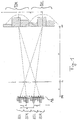
- FIG. 1 The structure of an autostereoscopic display is in FIG. 1 shown.
- the display consists of a matrix screen MB with the pixel plane PE, in front of which separating elements of a barrier grid are arranged in a separating plane TE parallel to the matrix screen MB. These are, for example, periodically spaced apart from each other L slots, prism elements or cylindrical lenses.
- the eyes of the beholder are in a viewing plane BE.
- the distances between pixel level PE, separation level TE and viewing level BE are marked with a and A.
- image columns BSR for the right stereo and BSL for the left stereo view are alternately applied - see also FIG.
- the barrier grid ensures that light emanating from the pixels of the image columns BSR falls into a right viewing zone EZR for a right eye of an observer and light emanating from the pixels of the image columns BSL falls into a left viewing zone BZL for a left eye of the observer.
- the viewing zones BZR and BZL are also referred to herein as stereo zones.
- the image columns run parallel to the optical elements of the barrier grid (lenses, slits), also referred to as the separation grid.
- Brightness focal points or intensities of the image columns of a stereo pair BSR-BSL have the distance p from each other in the pixel plane PE.
- the distance from stereo pair to stereo pair is indicated by q.
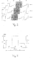
- a section of the pixel field of a panel forming the matrix screen shows the FIG. 2 ,
- the image columns BSR and BSL for the right and left stereo views run diagonally across the panel.
- Nine obliquely arranged, colored, intensity - changeable subpixels - in FIG. 2 marked by R for red, G for green, B for blue - each form one pixel. Viewed from the oblique stereo zones, this arrangement ensures the color purity of the pixels.
- the brightness of each subpixel is multiplied by a weight.
- the passage of these weights over the pixel lines is in FIG. 2 where RELIN stands for relative intensity. This function is the same for all pixel lines, offset by one subpixel only from line to line.
- an orientation of the image columns perpendicular to the lines would also be possible in the case of line-by-line cyclically interchanged or laterally shifted order of the colors of the subpixels.
- other arrangements of subpixels to a pixel In particular, each row of each pixel may also contain four or more than four subpixels.
- monochrome subpixels can alternatively be used.
- a matrix screen with multi-color pixels in which each successively arranged primary color pixels each form a functioning here as a subpixel, tunable by the colors multi-color pixels.
- a further embodiment of the invention provides that an odd number of subpixels - for example, five subpixels - is distributed in a row to one pixel each of both fields. Then, depending on the head position, a central subpixel can be assigned to one or the other field and, under certain conditions, also be mixed with image information of both fields.
- the brightness centers of gravity or intensities of intensity can thus be defined in the pixel plane move the image columns to the left or right.
- the stereo zones in the viewing plane BE move towards it, reinforced by the A / a times. If only the distance q between the image columns is changed, the viewing plane BE moves towards or away from the display.
- an in Fig. 1 set distance P between the stereo channels in the viewer's plane which is defined as the distance between a center of gravity of a resulting intensity distribution in the left viewing plane BZL and a center of gravity of a resulting intensity distribution in the right viewing zone BZR, within the viewing plane BE.
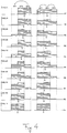
- FIG. 3 shows the course of a weighting of the intensity over a subpixel triple of a width b with three subpixels SP1, SP2 and SP3.
- the weights GW can be changed here only in 2 N discrete stages due to a digital control of the subpixels, so that the center of gravity S can also be moved only gradually.
- a shift to the full width of a subpixel with the greatest possible pixel brightness can be achieved if the total area under the staircase curve is set to 2/3 * b. This corresponds to the area of two subpixels, which can either be completely shifted to the two subpixels SP1 and SP2 or SP2 and SP3.
- the center of gravity then shifts b / 6 in one direction or the other, ie, in total by the width of a subpixel.
- the total area under the staircase - and thus the sacredness and color of the pixel - it remains unchanged: GW 1 + GW 2 + GW 3 constant
- GW1, GW2 and GW3 stand for the weights GW for the three subpixels SP1, SP2 and SP3.
- d GW 3 - GW 1 / GW 1 + GW 2 + GW 3 * b / 3
- FIG. 3 shows an arrangement in which the central subpixel SP2 all 2 N possible area shares are assigned, and the remaining 2 N are distributed to the two subpixels SP1 and SP3. With symmetrical weight distribution, the two outer subpixels each have 2 N-1 area shares.
- M can assume the values 0 ⁇ M ⁇ 2 N-1 .
- the smallest step size in this case is b / (3 * 2 N ).
- the last-mentioned step size also results if a surface element is removed or added to one of the outer subpixels SP1 or SP3.
- the area under the staircase differs only by a surface element from the 'target value' 2/3 * b.
- the associated variation in pixel brightness is virtually imperceptible to the viewer.
- P 65 mm
- Table shows, in particular for a series of viewing distances A, the associated distances q of the centers of gravity: A .DELTA.A q .DELTA.Q P .DELTA.P p Ap Ap / .DELTA.Q [Mm] [Mm] [Mm] [Mm] [Mm] [Mm] [Mm] [Mm] 450 -150 0.528712 0.0007 49 -16 .3520 0.088 123.6 475 -125 0.528562 0.0006 51 -14 .3335 0,069 123.6 500 -100 0.528427 0.0004 54 -11 .3168 0.053 123.6 525 -75 0.528305 0.0003 57 -8th .3017 0,038 123.6 550 -50 0.528194 0.0002 60 -5 .2880 0.024 123.6 575 -25 0.528093 0.0001 62 -3 .2755 0.011 123.6 600 0
- the viewing plane BE should be able to be tracked in increments of approximately 25 mm to 50 mm, which according to Table 1 requires a computational accuracy for q of
- ⁇ 0.0001 mm / 2 0.00005 mm. But that does not mean that this tight tolerance is required for the location of the image strips. This will be explained below: Due to the oblique pattern of the image columns in the pixel plane PE run a horizontal line. The meeting point of this line with the center of gravity of the first left image column now forms the reference point from which the distances of all other image columns to the right of it are measured.
- the stereo channels can be adjusted in the entire distance range of the eye distance, as long as it is less than 65 mm. For larger eye distances, the adjustment is difficult only at close range.
- a change in the head position of the observer is detected, in the preferred embodiment contactless with a tracking method using at least one video camera for observing the head position, wherein the driving of the subpixels to the detected change of the head position during a movement of the head Viewer is adjusted.
- the subpixels within each of the pixels with one in addition to the image information of the two stereo images line by line Controlled subpixel-dependent weighted intensity, so that by changing the weighting in the manner described the intensity center of gravity within the respective pixel and thus the center of gravity of the lateral intensity distribution of the light emanating from this pixel in the corresponding viewing zone BZR or BZL is laterally displaceable.
- the main emphases in the FIGS. 3 and 4 are denoted by S and are obtained by summing the weighted with the respective local coordinates of the subpixels of the corresponding pixel, are thereby within the pixels in a change in the viewing distance A, so the distance between the head position and matrix screen MB, by adjusting the weight of Intensities so that the lateral distance P between the centroid of the intensity distribution in the left viewing zone BZL and the centroid of the intensity distribution in the right viewing zone BZR remains constant within the viewing plane BE changing with the head position.
- the distance P should not deviate from the nominal value 65 mm by more than 3 mm.
- the intensities of the subpixels of all pixels in the matrix screen MB off Fig. 1 are weighted in such a way that the centers of gravity of the respective intensity distributions within the viewing plane BE in the viewing zones BZR and BZL are all in coincidence.
- the centers of intensities within the pixels for tracking are shifted laterally in proportion to a lateral change in head position, so that the centroids the intensities in the viewing zones BZR and BZL always coincide at least approximately with the positions of the two eyes of the observer.
- a lateral eye distance of the observer is determined, preferably with the video cameras, which are also used for detecting the head position.
- the intensities within the pixels are then weighted such that the lateral distance P between the centroid of the intensity distributions in the left viewing zone BZL and the centroid of the intensity distributions in the right viewing zone BZR within the viewing plane BE corresponds to the determined eye distance.
- the subpixels of the matrix screen MB are controlled to autostereoscopically display the image information to be perceived three-dimensionally by the viewer by multiplying, within each of the pixels, an intensity value resulting from the image information for each subpixel of the respective pixel with the corresponding weight GW the weights GW as values in the FIGS. 2 to 4 illustrated weighting function are interpretable for each pixel and wherein these weighting functions are independent of the image information and have a shape dependent on the head position and a location of the pixel.
- Another embodiment of the invention which is an alternative to the Fig. 1 described device provides that the barrier grid synchronized with the subpixels of the matrix screen MB is switchable between two states, to guide light emanating from the pixels alternately in the left viewing zone BZL and the right viewing zone BZR. Then, the pixels of the stereo image for the left eye and the pixels of the stereo image for the right eye - unlike the above-described embodiment - formed by the same subpixels, which are time-sequentially driven thereto, in synchronism with a switching of Barrier raster between the two states.
- a method which ensures a smooth, continuous electronic image tracking without perceptible Umschalt bine in all head movements of the viewer in parallel and at a distance from the matrix screen MB with consistently high imaging quality in terms of image resolution, channel crosstalk or other interference effects.
- This method has the advantage of adjusting the distance between the effective centers of gravity, ie the locations of highest radiation intensity, in the viewing zones BZL and BZR for the left and right observer eye to the eye distance of the observer and to keep constant with changes in the observer distance.
- the method can be implemented in a simple manner by a corresponding programming of a control device which activates the matrix screen MB.
- the method is simple and inexpensive to implement, where it can advantageously work in real time and is resistant to interference.
- a tracking is thus realized in autostereoscopic displays, in which the viewer retains a stereoscopic image impression even when changing position.
- the method described here enlarges the area in which the stereo image can be perceived in good quality. It is particularly advantageous in preferred embodiments of the invention that persons with different eye distances can equally well perceive the stereoscopic effect.
- the invention can be used advantageously for many different applications, for example in the context of gaming, minimally invasive surgery, multimedia, VR, advertising, remote control systems and educational applications, for example in museums.
- the device proposed by the present specification comprises a matrix screen MB having a plurality of intensity-variable subpixels arranged in rows and columns, which are combined into a plurality of subpixel groups for reproducing one pixel at a time.
- a barrier grid arranged parallel to the matrix screen MB, with which the light emanating from the pixels can be guided into in each case one of two adjacent viewing zones BZL and BZR, as well as a device for detecting a head position of a viewer and a control device for driving the subpixels of the matrix screen MB.
- the pixels are in each case assigned to one of two subgroups, these subgroups being defined by the light emanating from the pixels of one subgroup passing through the barrier grid into the left viewing zone BZL for a left viewer eye and the light emanating from the pixels of the other subgroup through the barrier grid into the right viewing zone BZR for a right viewer eye.
- the intensity with which an arbitrary subpixel is controlled is then obtained by multiplying an intensity resulting from the image information for the pixel to which this subpixel is assigned by a value of the weighting function assigned to this pixel.
- the weighting functions are now modified in such a way that the intensity centers S shift laterally within a pixel. Such an adaptation is carried out, in particular, when the viewing distance A is changed, such that a distance p between the intensity centroid S of a pixel radiating into the viewing zone BZL and the intensity centroid S of the corresponding pixel radiating into the other viewing zone BZR changes.
- the distance p is changed so that the lateral distance P between the center of gravity of the intensity distribution caused by the former pixel in the left viewing zone BZL and the center of gravity of the intensity distribution caused by the second pixel in the right viewing zone BZR is changed in which the viewing distance A is remote from the matrix screen MB (eg from the pixel plane PE or from the barrier grid) and remains constant with A changing viewing plane BE.
- the value of p has to be changed for this, results from simple trigonometric calculations, as the person skilled in the art can easily recognize from the geometric contexts, eg in Fig. 1 are shown.
Claims (14)
- Procédé de représentation autostéréoscopique d'informations d'image sur un écran à matrice (MB), sur lequel une pluralité de pixels est formée par respectivement un groupe de sous-pixels avec une pluralité de sous-pixels d'intensité variable, agencés en lignes et en colonnes, dans lequel- deux demi-images stéréoscopiques sont formées sur respectivement un de deux sous-groupes des pixels et la lumière partant des deux sous-groupes de pixels est conduite à travers une trame barrière dans deux zones d'observation voisines (BZL, BZR) de sorte que la lumière partant des pixels d'un premier des deux sous-groupes tombe dans une zone d'observation gauche (BZL) pour un oeil gauche et la lumière partant des pixels d'un deuxième des deux sous-groupes tombe dans une zone d'observation droite (BZR) pour un oeil droit d'un observateur,- dans lequel les sous-pixels sont commandés à l'intérieur de chacun des pixels avec une intensité pondérée en fonction des sous-pixels par ligne en plus des informations d'image de sorte qu'un centre de gravité d'intensité (S) à l'intérieur du pixel respectif et ainsi un centre de gravité d'une répartition d'intensité latérale de la lumière partant de ce pixel est déplaçable latéralement dans la zone d'observation (BZL, BZR) correspondante par une modification de la pondération,- dans lequel en outre une modification d'une position de la tête de l'observateur est détectée et une commande des sous-pixels est adaptée à la modification de la position de la tête- et les centres de gravité d'intensité (S) sont décalés à l'intérieur des pixels lors d'une modification d'une distance d'observation (A) entre la position de la tête et l'écran à matrice (MB) par une adaptation de la pondération des intensités de sorte qu'une distance latérale (P) entre le centre de gravité des répartitions d'intensité dans la zone d'observation gauche (BZL) et le centre de gravité des répartitions d'intensité dans la zone d'observation droite (BZR) reste constante dans un plan d'observation (BE) variant avec la position de la tête, par le fait qu'une distance latérale (p) entre le centre de gravité d'intensité (S) à l'intérieur d'un pixel du premier sous-groupe et le centre de gravité d'intensité (S) à l'intérieur du pixel le plus proche du deuxième sous-groupe est modifiée.
- Procédé selon la revendication 1, caractérisé en ce que les intensités des sous-pixels de tous les pixels sont pondérées de sorte qu'à l'intérieur du plan d'observation (BE) détecté avec la position de la tête, les centres de gravité des répartitions d'intensité de la lumière partant des différents pixels du premier sous-groupe dans la zone d'observation gauche (BZL) coïncident les uns aux autres et les centres de gravité des répartitions d'intensité de la lumière partant des différents pixels du deuxième sous-groupe dans la zone d'observation droite (BZR) coïncident les uns aux autres.
- Procédé selon l'une quelconque des revendications 1 ou 2, caractérisé en ce que les centres de gravité d'intensité (S) sont décalés latéralement à l'intérieur des pixels lors d'une modification latérale de la position de la tête par une adaptation de la pondération des intensités proportionnellement à cette modification.
- Procédé selon l'une quelconque des revendications 1 à 3, caractérisé en ce que pour l'actualisation de la modification de la position de la tête, une nouvelle association d'information d'image avec des sous-pixels, qui deviennent visibles par la modification à respectivement un autre oeil de l'observateur, a lieu en plus.
- Procédé selon l'une quelconque des revendications 1 à 4, caractérisé en ce qu'une valeur d'intensité résultant des informations d'image pour un pixel pour chaque sous-pixel du pixel est multipliée avec une valeur d'une fonction de pondération pour la commande des sous-pixels avec l'intensité pondérée en fonction des sous-pixels à l'intérieur de chacun des pixels, dans lequel cette fonction de pondération est indépendante des informations d'image et a une forme dépendant de la position de la tête et d'un lieu du pixel et définit pour chaque sous-pixel du pixel un poids (GW) dépendant du lieu à l'intérieur de chaque ligne.
- Procédé selon l'une quelconque des revendications 1 à 5, caractérisé en ce qu'en plus de la position de la tête, une distance oculaire latérale de l'observateur est déterminée et les intensités à l'intérieur des pixels sont pondérées de sorte que la distance latérale (P) entre le centre de gravité des répartitions d'intensité dans la zone d'observation gauche et le centre de gravité des répartitions d'intensité dans la zone d'observation droite correspond à la distance oculaire déterminée à l'intérieur du plan d'observation.
- Procédé selon l'une quelconque des revendications 1 à 6, caractérisé en ce que la modification de la position de la tête de l'observateur est détectée sans contact avec un procédé de suivi.
- Dispositif de représentation autostéréoscopique d'informations d'image, comprenant- un écran à matrice (MB) avec une pluralité de sous-pixels d'intensité variable, agencés en lignes et en colonnes qui sont regroupés en une pluralité de groupes de sous-pixels pour la restitution de respectivement un pixel,- une trame barrière agencée parallèlement à l'écran à matrice (MB), avec laquelle la lumière partant des pixels peut être conduite dans respectivement une de deux zones d'observation (BZL, BZR) voisines,- un dispositif de détection d'une position de la tête d'un observateur et- un dispositif de commande pour la commande des sous-pixels de l'écran à matrice (MB),caractérisé en ce
que le dispositif est aménagé du point de vue du programme pour la réalisation d'un procédé selon l'une quelconque des revendications 1 à 7. - Dispositif selon la revendication 8, caractérisé en ce que la trame barrière comprend des lignes de réseau, des éléments de prisme ou des lentilles cylindriques s'étendant parallèlement à une direction de colonne de l'écran à matrice (MB).
- Dispositif selon l'une quelconque des revendications 8 ou 9, caractérisé en ce que le dispositif de détection de la position de la tête comprend au moins une caméra vidéo pour un suivi sans contact.
- Dispositif selon l'une quelconque des revendications 8 à 10, caractérisé en ce qu'il comprend en outre un dispositif de détermination d'une distance oculaire de l'observateur.
- Dispositif selon l'une quelconque des revendications 8 à 11, caractérisé en ce que dans chaque ligne de l'écran à matrice (MB), des pixels d'un premier sous-groupe s'alternent avec des pixels d'un deuxième sous-groupe, dans lequel la lumière partant des pixels du premier sous-groupe est conduite dans une zone d'observation gauche (BZL) pour un oeil gauche et la lumière partant des pixels du deuxième sous-groupe est conduite dans une zone d'observation droite (BZR) pour un oeil droit de l'observateur.
- Dispositif selon l'une quelconque des revendications 8 à 12, caractérisé en ce que la trame barrière peut être commutée de manière synchronisée avec les sous-pixels de l'écran à matrice (MB) entre deux états pour conduire la lumière partant des pixels en alternance dans une zone d'observation gauche (BZL) pour un oeil gauche et dans une zone d'observation droite (BZR) pour un oeil droit de l'observateur.
- Dispositif selon l'une quelconque des revendications 8 à 13, caractérisé en ce que chaque pixel comprend au moins trois lignes de sous-pixels et dans chaque ligne au moins trois sous-pixels de différente couleur.
Applications Claiming Priority (2)
| Application Number | Priority Date | Filing Date | Title |
|---|---|---|---|
| DE102007055026A DE102007055026B4 (de) | 2007-11-15 | 2007-11-15 | Verfahren und Vorrichtung zum autostereoskopischen Darstellen von Bildinformationen |
| PCT/EP2008/009828 WO2009062752A1 (fr) | 2007-11-15 | 2008-11-14 | Procédé et dispositif de représentation autostéréoscopique d'informations d'image |
Publications (2)
| Publication Number | Publication Date |
|---|---|
| EP2215850A1 EP2215850A1 (fr) | 2010-08-11 |
| EP2215850B1 true EP2215850B1 (fr) | 2019-05-29 |
Family
ID=40316874
Family Applications (1)
| Application Number | Title | Priority Date | Filing Date |
|---|---|---|---|
| EP08848944.8A Not-in-force EP2215850B1 (fr) | 2007-11-15 | 2008-11-14 | Procédé et dispositif de représentation autostéréoscopique d'informations d'image |
Country Status (6)
| Country | Link |
|---|---|
| US (1) | US8441522B2 (fr) |
| EP (1) | EP2215850B1 (fr) |
| KR (1) | KR101356549B1 (fr) |
| BR (1) | BRPI0820529A2 (fr) |
| DE (1) | DE102007055026B4 (fr) |
| WO (1) | WO2009062752A1 (fr) |
Families Citing this family (19)
| Publication number | Priority date | Publication date | Assignee | Title |
|---|---|---|---|---|
| US8587639B2 (en) * | 2008-12-11 | 2013-11-19 | Alcatel Lucent | Method of improved three dimensional display technique |
| DE102009034355B3 (de) * | 2009-07-17 | 2011-01-27 | Fraunhofer-Gesellschaft zur Förderung der angewandten Forschung e.V. | Monitor und Verfahren zum Darstellen autostereoskopisch wahrnehmbarer Bilder |
| US8358335B2 (en) * | 2009-11-30 | 2013-01-22 | Fraunhofer-Gesellschaft Zur Foerderung Der Angewandten Forschung E.V. | Method for displaying image information and autostereoscopic screen |
| US8633972B2 (en) * | 2010-03-03 | 2014-01-21 | Fraunhofer-Geselschaft zur Foerderung der angewandten Forschung e.V. | Method for displaying image information and autostereoscopic screen |
| US8687051B2 (en) * | 2010-03-03 | 2014-04-01 | Fraunhofer-Gesellschaft Zur Foerderung Der Angewandten Forschung E.V. | Screen and method for representing picture information |
| DE102010021550B4 (de) * | 2010-05-21 | 2018-04-19 | Fraunhofer-Gesellschaft zur Förderung der angewandten Forschung e.V. | Bildwiedergabegerät und Verfahren zur Bildwiedergabe |
| JP5488212B2 (ja) * | 2010-06-04 | 2014-05-14 | 三菱電機株式会社 | 画像処理装置、画像処理方法および画像表示装置 |
| KR20120010404A (ko) * | 2010-07-26 | 2012-02-03 | 삼성전자주식회사 | 색유지형 선택적 부화소 렌더링을 이용한 다시점 디스플레이 시스템 및 방법 |
| KR101675961B1 (ko) * | 2010-12-29 | 2016-11-14 | 삼성전자주식회사 | 적응적 부화소 렌더링 장치 및 방법 |
| JP5874197B2 (ja) * | 2011-05-26 | 2016-03-02 | ソニー株式会社 | 表示装置および方法、並びにプログラム |
| JP6050941B2 (ja) * | 2011-05-26 | 2016-12-21 | サターン ライセンシング エルエルシーSaturn Licensing LLC | 表示装置および方法、並びにプログラム |
| JP5643160B2 (ja) * | 2011-07-01 | 2014-12-17 | 株式会社ジャパンディスプレイ | 表示装置 |
| WO2013110779A1 (fr) | 2012-01-26 | 2013-08-01 | Fraunhofer-Gesellschaft Zur Förderung Der Angewandten Forschung | Affichage auto-stéréoscopique et procédé d'affichage d'une image 3d |
| EP2699006A1 (fr) * | 2012-08-16 | 2014-02-19 | ESSILOR INTERNATIONAL (Compagnie Générale d'Optique) | Positionnement d'images sur des éléments d'affichage |
| EP2901674B1 (fr) * | 2012-09-26 | 2018-03-21 | Fraunhofer Gesellschaft zur Förderung der angewandten Forschung e.V. | Procédé d'affichage d'informations d'image et écran autostéréoscopique |
| CN103698889A (zh) * | 2013-12-18 | 2014-04-02 | 京东方科技集团股份有限公司 | 一种显示面板及显示装置 |
| GB2527548A (en) * | 2014-06-25 | 2015-12-30 | Sharp Kk | Variable barrier pitch correction |
| CN104703047B (zh) * | 2015-03-23 | 2018-03-23 | 北京京东方多媒体科技有限公司 | 一种调节显示参数的方法、遥控器及显示装置 |
| KR102415502B1 (ko) * | 2015-08-07 | 2022-07-01 | 삼성전자주식회사 | 복수의 사용자를 위한 라이트 필드 렌더링 방법 및 장치 |
Citations (1)
| Publication number | Priority date | Publication date | Assignee | Title |
|---|---|---|---|---|
| US5822117A (en) * | 1996-01-22 | 1998-10-13 | Kleinberger; Paul | Systems for three-dimensional viewing including first and second light polarizing layers |
Family Cites Families (5)
| Publication number | Priority date | Publication date | Assignee | Title |
|---|---|---|---|---|
| GB2317291A (en) | 1996-09-12 | 1998-03-18 | Sharp Kk | Observer tracking directional display |
| AU5651298A (en) | 1996-12-18 | 1998-07-15 | Technische Universitat Dresden | Method and device for the three-dimensional representation of information |
| DE19822342B4 (de) * | 1998-05-19 | 2004-03-04 | Seereal Technologies Gmbh | Anordnung zur dreidimensionalen Darstellung von Informationen |
| AU6862800A (en) * | 1999-09-07 | 2001-04-10 | 3Ality, Inc. | Systems for and methods of three dimensional viewing |
| DE102006031799B3 (de) * | 2006-07-06 | 2008-01-31 | Fraunhofer-Gesellschaft zur Förderung der angewandten Forschung e.V. | Verfahren zur autostereoskopischen Darstellung von Bildinformationen mit einer Anpassung an Änderungen der Kopfposition des Betrachters |
-
2007
- 2007-11-15 DE DE102007055026A patent/DE102007055026B4/de not_active Expired - Fee Related
-
2008
- 2008-11-14 BR BRPI0820529-9A patent/BRPI0820529A2/pt not_active IP Right Cessation
- 2008-11-14 EP EP08848944.8A patent/EP2215850B1/fr not_active Not-in-force
- 2008-11-14 US US12/682,075 patent/US8441522B2/en active Active
- 2008-11-14 WO PCT/EP2008/009828 patent/WO2009062752A1/fr active Application Filing
- 2008-11-14 KR KR1020107013156A patent/KR101356549B1/ko active IP Right Grant
Patent Citations (1)
| Publication number | Priority date | Publication date | Assignee | Title |
|---|---|---|---|---|
| US5822117A (en) * | 1996-01-22 | 1998-10-13 | Kleinberger; Paul | Systems for three-dimensional viewing including first and second light polarizing layers |
Also Published As
| Publication number | Publication date |
|---|---|
| US20100295928A1 (en) | 2010-11-25 |
| KR20100102116A (ko) | 2010-09-20 |
| EP2215850A1 (fr) | 2010-08-11 |
| WO2009062752A1 (fr) | 2009-05-22 |
| BRPI0820529A2 (pt) | 2015-08-11 |
| DE102007055026B4 (de) | 2011-04-28 |
| KR101356549B1 (ko) | 2014-01-29 |
| DE102007055026A1 (de) | 2009-05-28 |
| US8441522B2 (en) | 2013-05-14 |
Similar Documents
| Publication | Publication Date | Title |
|---|---|---|
| EP2215850B1 (fr) | Procédé et dispositif de représentation autostéréoscopique d'informations d'image | |
| EP2039173B1 (fr) | Procede de representation autostereoscopique d'informations d'image avec une adaptation aux changements de position de la tete de l'observateur | |
| DE69726087T2 (de) | Räumlicher Lichtmodulator mit horizontal überlappenden Bildelementen | |
| EP0946895B1 (fr) | Procede et dispositif pour la representation tridimensionnelle d'informations | |
| DE10003326C2 (de) | Verfahren und Anordnung zur räumlichen Darstellung | |
| EP1090510B1 (fr) | Procede et dispositif d'autostereoscopie | |
| DE102012108346B4 (de) | Stereoskopische Bildanzeigevorrichtung und Steuerungsverfahren für diese | |
| EP1779151A1 (fr) | Unite de prismes et de lenticules | |
| DE102009009443B3 (de) | Monitor und Verfahren zum Darstellen autostereoskopisch wahrnehmbarer Bilder | |
| EP1895782A2 (fr) | Dispositif d'affichage autostéréoscopique | |
| EP2997731B1 (fr) | Procédé de reproduction d'informations d'image et écran auto-stéréoscopique | |
| EP2901674B1 (fr) | Procédé d'affichage d'informations d'image et écran autostéréoscopique | |
| WO2005106563A2 (fr) | Systeme pour observer des images stereoscopiques | |
| DE19822342A1 (de) | Anordnung zur dreidimensionalen Darstellung von Informationen | |
| WO2008095584A1 (fr) | Dispositif de reproduction d'image autostéréoscopique pour produire une image stéréo réelle flottante | |
| DE102005013822A1 (de) | Verfahren zum Erzeugen von Bilddaten zur stereoskopischen Darstellung eines Objektes | |
| DE102009041783B4 (de) | Verfahren zum Darstellen von Bildinformationen und Bildschirm | |
| WO2021008780A1 (fr) | Affichage de base pour un système d'affichage autostéréoscopique | |
| DE102009056591A1 (de) | Verfahren zum Darstellen von Bildinformationen und autostereoskopischer Bildschirm | |
| EP1665816A1 (fr) | Procede et dispositif pour effectuer une representation perceptible tridimensionnellement | |
| DE19652689B4 (de) | Verfahren zur dreidimensionalen Darstellung von Information | |
| DE102009041784B4 (de) | Verfahren zum Darstellen von Bildinformationen und autostereoskopischer Bildschirm | |
| DE102004051355A1 (de) | Anordnung zur räumlich wahrnehmbaren Darstellung | |
| DE102010045467A1 (de) | Verfahren und Anordnung zur wahlweise zwei- oder dreidimensionalen Darstellung | |
| DE10325146A1 (de) | Verfahren und Anordnung zur räumlichen Darstellung |
Legal Events
| Date | Code | Title | Description |
|---|---|---|---|
| PUAI | Public reference made under article 153(3) epc to a published international application that has entered the european phase |
Free format text: ORIGINAL CODE: 0009012 |
|
| 17P | Request for examination filed |
Effective date: 20100615 |
|
| AK | Designated contracting states |
Kind code of ref document: A1 Designated state(s): AT BE BG CH CY CZ DE DK EE ES FI FR GB GR HR HU IE IS IT LI LT LU LV MC MT NL NO PL PT RO SE SI SK TR |
|
| AX | Request for extension of the european patent |
Extension state: AL BA MK RS |
|
| DAX | Request for extension of the european patent (deleted) | ||
| STAA | Information on the status of an ep patent application or granted ep patent |
Free format text: STATUS: EXAMINATION IS IN PROGRESS |
|
| 17Q | First examination report despatched |
Effective date: 20171211 |
|
| REG | Reference to a national code |
Ref country code: DE Ref legal event code: R079 Ref document number: 502008016778 Country of ref document: DE Free format text: PREVIOUS MAIN CLASS: H04N0013040000 Ipc: H04N0013300000 |
|
| GRAP | Despatch of communication of intention to grant a patent |
Free format text: ORIGINAL CODE: EPIDOSNIGR1 |
|
| STAA | Information on the status of an ep patent application or granted ep patent |
Free format text: STATUS: GRANT OF PATENT IS INTENDED |
|
| RIC1 | Information provided on ipc code assigned before grant |
Ipc: H04N 13/30 20180101AFI20181112BHEP Ipc: H04N 13/31 20180101ALI20181112BHEP Ipc: H04N 13/315 20180101ALI20181112BHEP Ipc: H04N 13/371 20180101ALI20181112BHEP Ipc: H04N 13/373 20180101ALI20181112BHEP Ipc: H04N 13/376 20180101ALI20181112BHEP Ipc: G02B 27/22 20180101ALI20181112BHEP |
|
| INTG | Intention to grant announced |
Effective date: 20181217 |
|
| RIC1 | Information provided on ipc code assigned before grant |
Ipc: H04N 13/315 20180101ALI20181112BHEP Ipc: H04N 13/30 20180101AFI20181112BHEP Ipc: H04N 13/373 20180101ALI20181112BHEP Ipc: H04N 13/31 20180101ALI20181112BHEP Ipc: H04N 13/371 20180101ALI20181112BHEP Ipc: H04N 13/376 20180101ALI20181112BHEP Ipc: G02B 27/22 20180101ALI20181112BHEP |
|
| GRAS | Grant fee paid |
Free format text: ORIGINAL CODE: EPIDOSNIGR3 |
|
| GRAA | (expected) grant |
Free format text: ORIGINAL CODE: 0009210 |
|
| STAA | Information on the status of an ep patent application or granted ep patent |
Free format text: STATUS: THE PATENT HAS BEEN GRANTED |
|
| AK | Designated contracting states |
Kind code of ref document: B1 Designated state(s): AT BE BG CH CY CZ DE DK EE ES FI FR GB GR HR HU IE IS IT LI LT LU LV MC MT NL NO PL PT RO SE SI SK TR |
|
| REG | Reference to a national code |
Ref country code: GB Ref legal event code: FG4D Free format text: NOT ENGLISH |
|
| REG | Reference to a national code |
Ref country code: CH Ref legal event code: EP |
|
| REG | Reference to a national code |
Ref country code: AT Ref legal event code: REF Ref document number: 1138971 Country of ref document: AT Kind code of ref document: T Effective date: 20190615 |
|
| REG | Reference to a national code |
Ref country code: DE Ref legal event code: R096 Ref document number: 502008016778 Country of ref document: DE |
|
| REG | Reference to a national code |
Ref country code: IE Ref legal event code: FG4D Free format text: LANGUAGE OF EP DOCUMENT: GERMAN |
|
| REG | Reference to a national code |
Ref country code: NL Ref legal event code: MP Effective date: 20190529 |
|
| REG | Reference to a national code |
Ref country code: LT Ref legal event code: MG4D |
|
| PG25 | Lapsed in a contracting state [announced via postgrant information from national office to epo] |
Ref country code: FI Free format text: LAPSE BECAUSE OF FAILURE TO SUBMIT A TRANSLATION OF THE DESCRIPTION OR TO PAY THE FEE WITHIN THE PRESCRIBED TIME-LIMIT Effective date: 20190529 Ref country code: LT Free format text: LAPSE BECAUSE OF FAILURE TO SUBMIT A TRANSLATION OF THE DESCRIPTION OR TO PAY THE FEE WITHIN THE PRESCRIBED TIME-LIMIT Effective date: 20190529 Ref country code: HR Free format text: LAPSE BECAUSE OF FAILURE TO SUBMIT A TRANSLATION OF THE DESCRIPTION OR TO PAY THE FEE WITHIN THE PRESCRIBED TIME-LIMIT Effective date: 20190529 Ref country code: SE Free format text: LAPSE BECAUSE OF FAILURE TO SUBMIT A TRANSLATION OF THE DESCRIPTION OR TO PAY THE FEE WITHIN THE PRESCRIBED TIME-LIMIT Effective date: 20190529 Ref country code: NO Free format text: LAPSE BECAUSE OF FAILURE TO SUBMIT A TRANSLATION OF THE DESCRIPTION OR TO PAY THE FEE WITHIN THE PRESCRIBED TIME-LIMIT Effective date: 20190829 Ref country code: ES Free format text: LAPSE BECAUSE OF FAILURE TO SUBMIT A TRANSLATION OF THE DESCRIPTION OR TO PAY THE FEE WITHIN THE PRESCRIBED TIME-LIMIT Effective date: 20190529 Ref country code: PT Free format text: LAPSE BECAUSE OF FAILURE TO SUBMIT A TRANSLATION OF THE DESCRIPTION OR TO PAY THE FEE WITHIN THE PRESCRIBED TIME-LIMIT Effective date: 20190930 |
|
| PG25 | Lapsed in a contracting state [announced via postgrant information from national office to epo] |
Ref country code: GR Free format text: LAPSE BECAUSE OF FAILURE TO SUBMIT A TRANSLATION OF THE DESCRIPTION OR TO PAY THE FEE WITHIN THE PRESCRIBED TIME-LIMIT Effective date: 20190830 Ref country code: BG Free format text: LAPSE BECAUSE OF FAILURE TO SUBMIT A TRANSLATION OF THE DESCRIPTION OR TO PAY THE FEE WITHIN THE PRESCRIBED TIME-LIMIT Effective date: 20190829 Ref country code: LV Free format text: LAPSE BECAUSE OF FAILURE TO SUBMIT A TRANSLATION OF THE DESCRIPTION OR TO PAY THE FEE WITHIN THE PRESCRIBED TIME-LIMIT Effective date: 20190529 |
|
| PG25 | Lapsed in a contracting state [announced via postgrant information from national office to epo] |
Ref country code: SK Free format text: LAPSE BECAUSE OF FAILURE TO SUBMIT A TRANSLATION OF THE DESCRIPTION OR TO PAY THE FEE WITHIN THE PRESCRIBED TIME-LIMIT Effective date: 20190529 Ref country code: EE Free format text: LAPSE BECAUSE OF FAILURE TO SUBMIT A TRANSLATION OF THE DESCRIPTION OR TO PAY THE FEE WITHIN THE PRESCRIBED TIME-LIMIT Effective date: 20190529 Ref country code: DK Free format text: LAPSE BECAUSE OF FAILURE TO SUBMIT A TRANSLATION OF THE DESCRIPTION OR TO PAY THE FEE WITHIN THE PRESCRIBED TIME-LIMIT Effective date: 20190529 Ref country code: CZ Free format text: LAPSE BECAUSE OF FAILURE TO SUBMIT A TRANSLATION OF THE DESCRIPTION OR TO PAY THE FEE WITHIN THE PRESCRIBED TIME-LIMIT Effective date: 20190529 Ref country code: RO Free format text: LAPSE BECAUSE OF FAILURE TO SUBMIT A TRANSLATION OF THE DESCRIPTION OR TO PAY THE FEE WITHIN THE PRESCRIBED TIME-LIMIT Effective date: 20190529 Ref country code: NL Free format text: LAPSE BECAUSE OF FAILURE TO SUBMIT A TRANSLATION OF THE DESCRIPTION OR TO PAY THE FEE WITHIN THE PRESCRIBED TIME-LIMIT Effective date: 20190529 |
|
| PG25 | Lapsed in a contracting state [announced via postgrant information from national office to epo] |
Ref country code: IT Free format text: LAPSE BECAUSE OF FAILURE TO SUBMIT A TRANSLATION OF THE DESCRIPTION OR TO PAY THE FEE WITHIN THE PRESCRIBED TIME-LIMIT Effective date: 20190529 |
|
| REG | Reference to a national code |
Ref country code: DE Ref legal event code: R097 Ref document number: 502008016778 Country of ref document: DE |
|
| PG25 | Lapsed in a contracting state [announced via postgrant information from national office to epo] |
Ref country code: TR Free format text: LAPSE BECAUSE OF FAILURE TO SUBMIT A TRANSLATION OF THE DESCRIPTION OR TO PAY THE FEE WITHIN THE PRESCRIBED TIME-LIMIT Effective date: 20190529 |
|
| PLBE | No opposition filed within time limit |
Free format text: ORIGINAL CODE: 0009261 |
|
| STAA | Information on the status of an ep patent application or granted ep patent |
Free format text: STATUS: NO OPPOSITION FILED WITHIN TIME LIMIT |
|
| PG25 | Lapsed in a contracting state [announced via postgrant information from national office to epo] |
Ref country code: PL Free format text: LAPSE BECAUSE OF FAILURE TO SUBMIT A TRANSLATION OF THE DESCRIPTION OR TO PAY THE FEE WITHIN THE PRESCRIBED TIME-LIMIT Effective date: 20190529 |
|
| 26N | No opposition filed |
Effective date: 20200303 |
|
| PG25 | Lapsed in a contracting state [announced via postgrant information from national office to epo] |
Ref country code: SI Free format text: LAPSE BECAUSE OF FAILURE TO SUBMIT A TRANSLATION OF THE DESCRIPTION OR TO PAY THE FEE WITHIN THE PRESCRIBED TIME-LIMIT Effective date: 20190529 |
|
| REG | Reference to a national code |
Ref country code: CH Ref legal event code: PL |
|
| PG25 | Lapsed in a contracting state [announced via postgrant information from national office to epo] |
Ref country code: MC Free format text: LAPSE BECAUSE OF FAILURE TO SUBMIT A TRANSLATION OF THE DESCRIPTION OR TO PAY THE FEE WITHIN THE PRESCRIBED TIME-LIMIT Effective date: 20190529 Ref country code: CH Free format text: LAPSE BECAUSE OF NON-PAYMENT OF DUE FEES Effective date: 20191130 Ref country code: LU Free format text: LAPSE BECAUSE OF NON-PAYMENT OF DUE FEES Effective date: 20191114 Ref country code: LI Free format text: LAPSE BECAUSE OF NON-PAYMENT OF DUE FEES Effective date: 20191130 |
|
| REG | Reference to a national code |
Ref country code: BE Ref legal event code: MM Effective date: 20191130 |
|
| PG25 | Lapsed in a contracting state [announced via postgrant information from national office to epo] |
Ref country code: IE Free format text: LAPSE BECAUSE OF NON-PAYMENT OF DUE FEES Effective date: 20191114 |
|
| PG25 | Lapsed in a contracting state [announced via postgrant information from national office to epo] |
Ref country code: BE Free format text: LAPSE BECAUSE OF NON-PAYMENT OF DUE FEES Effective date: 20191130 |
|
| REG | Reference to a national code |
Ref country code: AT Ref legal event code: MM01 Ref document number: 1138971 Country of ref document: AT Kind code of ref document: T Effective date: 20191114 |
|
| PG25 | Lapsed in a contracting state [announced via postgrant information from national office to epo] |
Ref country code: AT Free format text: LAPSE BECAUSE OF NON-PAYMENT OF DUE FEES Effective date: 20191114 |
|
| PGFP | Annual fee paid to national office [announced via postgrant information from national office to epo] |
Ref country code: GB Payment date: 20201119 Year of fee payment: 13 Ref country code: DE Payment date: 20201126 Year of fee payment: 13 Ref country code: FR Payment date: 20201120 Year of fee payment: 13 |
|
| PG25 | Lapsed in a contracting state [announced via postgrant information from national office to epo] |
Ref country code: CY Free format text: LAPSE BECAUSE OF FAILURE TO SUBMIT A TRANSLATION OF THE DESCRIPTION OR TO PAY THE FEE WITHIN THE PRESCRIBED TIME-LIMIT Effective date: 20190529 |
|
| PG25 | Lapsed in a contracting state [announced via postgrant information from national office to epo] |
Ref country code: IS Free format text: LAPSE BECAUSE OF FAILURE TO SUBMIT A TRANSLATION OF THE DESCRIPTION OR TO PAY THE FEE WITHIN THE PRESCRIBED TIME-LIMIT Effective date: 20190929 |
|
| PG25 | Lapsed in a contracting state [announced via postgrant information from national office to epo] |
Ref country code: HU Free format text: LAPSE BECAUSE OF FAILURE TO SUBMIT A TRANSLATION OF THE DESCRIPTION OR TO PAY THE FEE WITHIN THE PRESCRIBED TIME-LIMIT; INVALID AB INITIO Effective date: 20081114 Ref country code: MT Free format text: LAPSE BECAUSE OF FAILURE TO SUBMIT A TRANSLATION OF THE DESCRIPTION OR TO PAY THE FEE WITHIN THE PRESCRIBED TIME-LIMIT Effective date: 20190529 |
|
| REG | Reference to a national code |
Ref country code: DE Ref legal event code: R119 Ref document number: 502008016778 Country of ref document: DE |
|
| GBPC | Gb: european patent ceased through non-payment of renewal fee |
Effective date: 20211114 |
|
| PG25 | Lapsed in a contracting state [announced via postgrant information from national office to epo] |
Ref country code: GB Free format text: LAPSE BECAUSE OF NON-PAYMENT OF DUE FEES Effective date: 20211114 Ref country code: DE Free format text: LAPSE BECAUSE OF NON-PAYMENT OF DUE FEES Effective date: 20220601 |
|
| PG25 | Lapsed in a contracting state [announced via postgrant information from national office to epo] |
Ref country code: FR Free format text: LAPSE BECAUSE OF NON-PAYMENT OF DUE FEES Effective date: 20211130 |